large specalog for 315f l hydraulic excavator, … · 315f l hydraulic excavator 2017 engine drive...
TRANSCRIPT
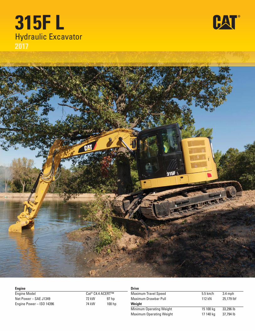
315F L Hydraulic Excavator 2017
Engine Drive
Engine Model Cat® C4.4 ACERT™ Maximum Travel Speed 5.5 km/h 3.4 mph
Net Power – SAE J1349 72 kW 97 hp Maximum Drawbar Pull 112 kN 25,179 lbf
Engine Power – ISO 14396 74 kW 100 hp Weight
Minimum Operating Weight 15 100 kg 33,296 lb
Maximum Operating Weight 17 140 kg 37,794 lb

315F L Hydraulic Excavator Specifications
Engine
Engine Model Cat C4.4 ACERT
Net Power – SAE J1349 72 kW 97 hp
Engine Power – ISO 14396 74 kW 100 hp
Bore 105 mm 4.1 in
Stroke 127 mm 5.0 in
Displacement 4.4 L 270 in3
Weight
Minimum Operating Weight* 15 100 kg 33,296 lb
Maximum Operating Weight** 17 140 kg 37,794 lb
*4.65 m (15'3") reach boom, 2.8 m (9'2") stick, 500 mm (20") shoes, no blade
** Power offset boom, 2.13 m (6'11'') stick, 700 mm (28") shoes, blade
Hydraulic System
Main System – Maximum Flow 256 L/min 68 gal/min (Total)
Maximum Pressure – Equipment 30 500 kPa 4,420 psi
Maximum Pressure – Power Offset 29 900 kPa 4,340 psi Boom (optional)
Maximum Pressure – Travel 35 000 kPa 5,080 psi
Maximum Pressure – Swing 23 000 kPa 3,340 psi
Pilot System – Maximum Flow 19 L/min 5 gal/min
Pilot System – Maximum Pressure 4120 kPa 600 psi
Boom Cylinder – Bore 110 mm 4.3 in
Boom Cylinder – Stroke 1000 mm 39.4 in
Stick Cylinder – Bore 120 mm 4.7 in
Stick Cylinder – Stroke 1197 mm 47.1 in
Bucket Cylinder – Bore 100 mm 3.9 in
Bucket Cylinder – Stroke 939 mm 37.0 in
Drive
Maximum Travel Speed 5.5 km/h 3.4 mph
Maximum Drawbar Pull 112 kN 25,179 lbf
Swing Mechanism
Swing Speed 11 rpm
Swing Torque 30.9 kN·m 22,790 lbf-ft
Service Refill Capacities
Fuel Tank Capacity 178 L 47 gal
DEF Tank Capacity 19 L 5 gal
Cooling System 28 L 7.4 gal
Engine Oil (with filter)
Swing Drive (each)
Final Drive (each)
Hydraulic System (including tank)
Hydraulic Tank
Track
13.5 L
3 L
3 L
160 L
84 L
3.6 gal
0.8 gal
0.8 gal
42.3 gal
22.2 gal
Long Undercarriage
Number of Shoes (each side) 46 pieces
Number of Track Rollers (each side) 7 pieces
Number of Carrier Rollers (each side) 2 pieces
18

315F L Hydraulic Excavator Specifications
Dimensions All dimensions are approximate.
2
3
1 9
10
6 7 4 8 5
Boom Type Reach Boom 4.65 m (15'3") Power Offset Boom
Stick Size R3.0 m R2.8 m 2.13 m (9'10") (9'2") (6'11")
1 Shipping Height* 3000 mm 9'10" 3030 mm 9'11" 3000 mm 9'10"
Shipping Height at Boom Top 2750 mm 9'0" 3030 mm 9'11" 2780 mm 9'1"
Shipping Height with Hand Rail 3000 mm 9'10" 3000 mm 9'10" 3000 mm 9'10"
Shipping Height with Top Guard 2950 mm 9'8" 2950 mm 9'8" 2950 mm 9'8"
2 Shipping Length
Long Undercarriage 7450 mm 24'5" 7440 mm 24'5" 7560 mm 24'10"
Long Undercarriage with Blade 8010 mm 26'3" 8010 mm 26'3" 8120 mm 26'8"
3 Tail Swing Radius
Heavy Counterweight 1530 mm 5'0" 1530 mm 5'0" 1530 mm 5'0"
4 Length to Center of Rollers 3040 mm 10'0" 3040 mm 10'0" 3040 mm 10'0"
5 Track Length 3750 mm 12'4" 3750 mm 12'4" 3750 mm 12'4"
6 Ground Clearance 440 mm 1'5" 440 mm 1'5" 440 mm 1'5"
7 Track Gauge 1990 mm 6'6" 1990 mm 6'6" 1990 mm 6'6"
8 Transport Width
500 mm (20") Shoes 2490 mm 8'2" 2490 mm 8'2" 2490 mm 8'2"
600 mm (24") Shoes 2590 mm 8'6" 2590 mm 8'6" 2590 mm 8'6"
700 mm (28") Shoes 2690 mm 8'10" 2690 mm 8'10" 2690 mm 8'10"
9 Cab Height 2810 mm 9'3" 2810 mm 9'3" 2810 mm 9'3"
Cab Height with Top Guard 2950 mm 9'8" 2950 mm 9'8" 2950 mm 9'8"
10 Counterweight Clearance** 860 mm 2'10" 860 mm 2'10" 860 mm 2'10"
*Including shoe lug height.
**Without shoe lug height.
All dimensions were calculated with 900 mm (35") wide GD bucket with 0.53 m3 (0.69 yd3) capacity and 1200 mm (3'11") tip radius.
19

315F L Hydraulic Excavator Specifications
Working Ranges All dimensions are approximate.
3
4
5
2
7 61
Boom Type Reach Boom 4.65 m (15'3")
Stick Size R3.0 m R2.8 m (9'10") (9'2")
1 Maximum Digging Depth 5950 mm 19'6" 5750 mm 18'10"
2 Maximum Reach at Ground Level 8680 mm 28'6" 8490 mm 27'10"
3 Maximum Cutting Height 9640 mm 31'8" 9480 mm 31'1"
4 Maximum Loading Height 7190 mm 23'7" 7030 mm 23'1"
5 Minimum Loading Height 2060 mm 6'9" 2240 mm 7'4"
6 Maximum Depth Cut for 2440 mm (8'0") Level Bottom 5770 mm 18'9'' 5560 mm 18'2''
7 Maximum Vertical Wall Digging Depth 5280 mm 17'4" 5090 mm 16'8"
All dimensions were calculated with 900 mm (35") wide GD bucket with 0.53 m3 (0.69 yd3) capacity and 1200 mm (3'11") tip radius.
20
315F L Hydraulic Excavator Specifications
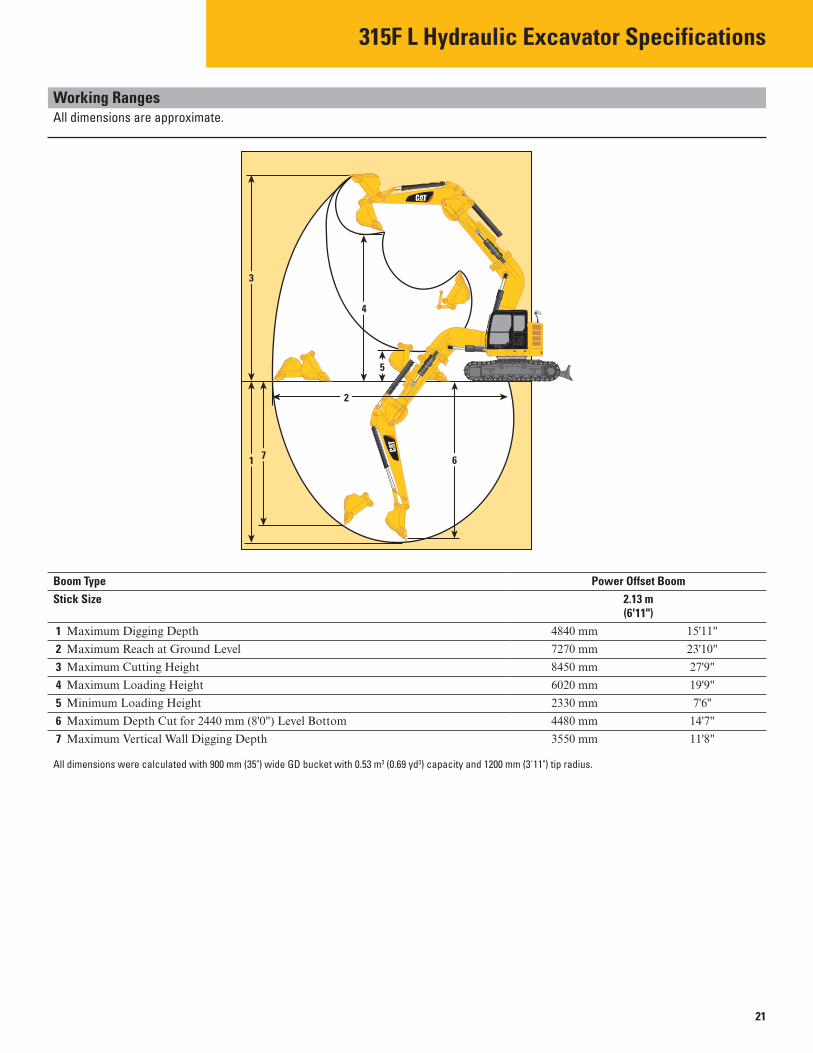
Working Ranges All dimensions are approximate.
3
4
5
2
7 61
Boom Type Power Offset Boom
Stick Size 2.13 m (6'11")
1 Maximum Digging Depth 4840 mm 15'11"
2 Maximum Reach at Ground Level 7270 mm 23'10"
3 Maximum Cutting Height 8450 mm 27'9"
4 Maximum Loading Height 6020 mm 19'9"
5 Minimum Loading Height 2330 mm 7'6''
6 Maximum Depth Cut for 2440 mm (8'0") Level Bottom 4480 mm 14'7"
7 Maximum Vertical Wall Digging Depth 3550 mm 11'8"
All dimensions were calculated with 900 mm (35") wide GD bucket with 0.53 m3 (0.69 yd3) capacity and 1200 mm (3'11") tip radius.
21
315F L Hydraulic Excavator Specifications
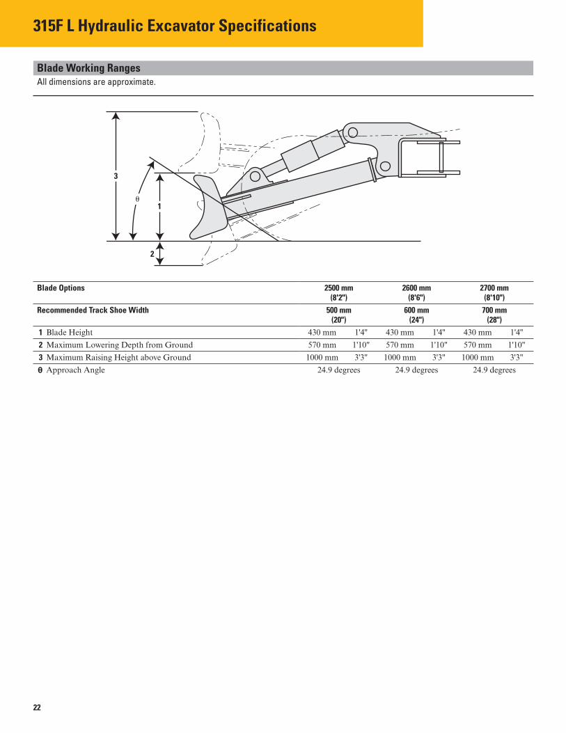
Blade Working Ranges All dimensions are approximate.
3
1
2
�
Blade Options 2500 mm 2600 mm 2700 mm (8'2") (8'6") (8'10")
Recommended Track Shoe Width 500 mm 600 mm 700 mm (20") (24") (28")
1 Blade Height 430 mm 1'4'' 430 mm 1'4'' 430 mm 1'4''
2 Maximum Lowering Depth from Ground 570 mm 1'10" 570 mm 1'10" 570 mm 1'10"
3 Maximum Raising Height above Ground 1000 mm 3'3" 1000 mm 3'3" 1000 mm 3'3"
θ Approach Angle 24.9 degrees 24.9 degrees 24.9 degrees
22
315F L Hydraulic Excavator Specifications
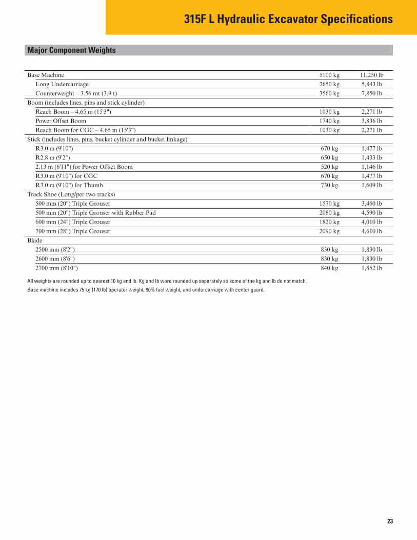
Major Component Weights
Base Machine 5100 kg 11,250 lb
Long Undercarriage 2650 kg 5,843 lb
Counterweight – 3.56 mt (3.9 t) 3560 kg 7,850 lb
Boom (includes lines, pins and stick cylinder)
Reach Boom – 4.65 m (15'3") 1030 kg 2,271 lb
Power Offset Boom 1740 kg 3,836 lb
Reach Boom for CGC – 4.65 m (15'3") 1030 kg 2,271 lb
Stick (includes lines, pins, bucket cylinder and bucket linkage)
R3.0 m (9'10") 670 kg 1,477 lb
R2.8 m (9'2") 650 kg 1,433 lb
2.13 m (6'11") for Power Offset Boom 520 kg 1,146 lb
R3.0 m (9'10") for CGC 670 kg 1,477 lb
R3.0 m (9'10") for Thumb 730 kg 1,609 lb
Track Shoe (Long/per two tracks)
500 mm (20") Triple Grouser 1570 kg 3,460 lb
500 mm (20") Triple Grouser with Rubber Pad 2080 kg 4,590 lb
600 mm (24") Triple Grouser 1820 kg 4,010 lb
700 mm (28") Triple Grouser 2090 kg 4,610 lb
Blade
2500 mm (8'2") 830 kg 1,830 lb
2600 mm (8'6") 830 kg 1,830 lb
2700 mm (8'10") 840 kg 1,852 lb
All weights are rounded up to nearest 10 kg and lb. Kg and lb were rounded up separately so some of the kg and lb do not match.
Base machine includes 75 kg (170 lb) operator weight, 90% fuel weight, and undercarriage with center guard.
23

315F L Hydraulic Excavator Specifications
Operating Weight and Ground Pressure
700 mm (28") 600 mm (24") 500 mm (20") Triple Grouser Shoes Triple Grouser Shoes Triple Grouser Shoes
kg lb kPa psi kg lb kPa psi kg lb kPa psi
Long Undercarriage without Blade
Reach Boom – 4.65 m (15'3")
R3.0 m (9'10") 15 640 34,486 33.3 4.8 15 370 33,891 38.2 5.5 15 120 33,340 45.1 6.5
R2.8 m (9'2") 15 620 34,442 33.3 4.8 15 350 33,847 38.1 5.5 15 100 33,296 45.0 6.5
Long Undercarriage with Blade
Reach Boom – 4.65 m (15'3")
R3.0 m (9'10") 16 480 36,338 35.1 5.1 16 200 35,721 40.3 5.8 15 950 35,170 47.6 6.9
R2.8 m (9'2") 16 460 36,294 35.1 5.1 16 180 35,677 40.2 5.8 15 930 35,126 47.5 6.9
Power Offset Boom
2.13 m (6'11") 17 140 37,794 36.5 5.3 16 860 37,176 41.9 6.1 16 600 36,603 49.5 7.2
Bucket and Stick Forces
Boom Type Reach Boom 4.65 m (15'3") Power Offset Boom
Stick Size R3.0 m (9'10") R2.8 m (9'2") 2.13 m (6'11")
General Duty
Bucket Digging Force (SAE) 85 kN 19,200 lbf 85 kN 19,200 lbf 78 kN 17,500 lbf
Stick Digging Force (SAE) 57 kN 12,800 lbf 60 kN 13,500 lbf 61 kN 13,700 lbf
Severe Duty
Bucket Digging Force (SAE) 83 kN 18,700 lbf 83 kN 18,700 lbf 76 kN 17,100 lbf
Stick Digging Force (SAE) 57 kN 12,800 lbf 60 kN 13,400 lbf 61 kN 13,700 lbf
Caterpillar recommends using appropriate work tools to maximize the value customers receive from our products. Use of work tools, including buckets, which are outside of Caterpillar’s recommendations or specifications for weight, dimensions, flows, pressures, etc. may result in less-than-optimal performance, including but not limited to reductions in production, stability, reliability, and component durability. Improper use of a work tool resulting in sweeping, prying, twisting and/or catching of heavy loads will reduce the life of the boom and stick.
24

315F L Hydraulic Excavator Specifications
Reach Boom Lift Capacities – Counterweight: 3.56 mt (3.9 t) – Blade Down
3.0 m (9'10") 4.65 m (15'3") 600 mm (24") 3040 mm (10'0")
R3.0
3750 mm (12'4")1990 mm (6'6")
7.5 m kg 25.0 ft lb 6.0 m kg
20.0 ft lb 4.5 m
15.0 ft kg lb
3.0 m 10.0 ft
kg lb
1.5 m 5.0 ft 0.0 m 0.0 ft
kg lb kg lb
–1.5 m –5.0 ft
kg lb
–3.0 m kg –10.0 ft lb –4.5 m kg
–15.0 ft lb
*2600 *2600 *2500 *2500 *5,600 *5,600
*3450 *3450 *2350 *2350 *2100 *2100 *7,550 *7,550 *4,650 *4,650 *3700 *3700 *3400 3050 *2000 *2000
*8,050 *8,050 *7,400 6,500 *4,350 *4,350 *5900 *5900 *4350 *4350 *3650 2950 *2000 *2000
*12,700 *12,700 *9,450 *9,450 *7,900 6,350 *4,350 *4,350 *8050 7900 *5150 4300 *3950 2850 *2100 2000
*17,350 16,950 *11,150 9,200 *8,550 6,100 *4,550 4,400 *7350 *7350 *5600 4050 *4100 2750 *2300 2050
*16,950 15,950 *12,100 8,750 *8,850 5,850 *5,050 4,450 *4550 *4550 *8050 7300 *5400 3950 *3900 2650 *2700 2200
*10,150 *10,150 *17,450 15,700 *11,700 8,500 *8,400 5,750 *6,000 4,850 *7550 *7550 *6450 *6450 *4500 3950 *2950 2700 *2850 2700
*16,950 *16,950 *13,950 *13,950 *9,650 8,550 *6,300 5,950 *3550 *3550 *2150 *2150
*7,350 *7,350 *4,500 *4,500
m ft
4.54 14.33
6.07 19.68
6.96 22.72
7.43 24.36
7.58 24.88
7.43 24.36
6.94 22.73
6.04 19.71
4.49 14.39
ISO 10567
*Indicates that the load is limited by hydraulic lifting capacity rather than tipping load. The above loads are in compliance with hydraulic excavator lift capacity standard ISO 10567:2007. They do not exceed 87% of hydraulic lifting capacity or 75% of tipping load. Weight of all lifting accessories must be deducted from the above lifting capacities. Lifting capacities are based on the machine standing on a firm, uniform supporting surface. The use of a work tool attachment point to handle/lift objects, could affect the machine lift performance.
Lift capacity stays with ±5% for all available track shoes.
Always refer to the appropriate Operation and Maintenance Manual for specific product information.
1.5 m/5.0 ft 3.0 m/10.0 ft 4.5 m/15.0 ft 6.0 m/20.0 ft
25

315F L Hydraulic Excavator Specifications
Reach Boom Lift Capacities – Counterweight: 3.56 mt (3.9 t) – Blade Down
3.0 m (9'10") 4.65 m (15'3")
1.5 m/5.0 ft
500 mm (20") 3040 mm (10'0")
R3.0
3750 mm (12'4")1990 mm (6'6")
7.5 m 25.0 ft
kg lb
6.0 m 20.0 ft
kg lb
4.5 m 15.0 ft
kg lb
3.0 m 10.0 ft
kg lb
1.5 m 5.0 ft 0.0 m 0.0 ft
kg lb kg lb
*4550 *10,150
*7550 *16,950
–1.5 m –5.0 ft
kg lb
–3.0 m –10.0 ft
kg lb
–4.5 m –15.0 ft
kg lb
*4550 *10,150
*7550 *16,950
3.0 m/10.0 ft 4.5 m/15.0 ft
m ft
4.54 14.33
6.07 19.68
6.96 22.72
7.43 24.36
7.58 24.88
7.43 24.36
6.94 22.73
6.04 19.71
4.49 14.39
*5900 *12,700
*8050 *17,350
*7350 *16,950
*8050 *17,450
*6450 *13,950
*3550 *7,350
*5900 *12,700
7550 16,250
7100 15,250
7000 15,000 *6450
*13,950 *3550
*7,350
*2600
*3450 *7,550 *3700
*8,050 *4350
*9,450 *5150
*11,150 *5600
*12,100 *5400
*11,700 *4500
*9,650
*2600
*3450 *7,550 *3700
*8,050 *4350 9,450 4100
8,850 3900
8,400 3800
8,150 3800
8,200
ISO 10567
6.0 m/20.0 ft
*2350
*3400 *7,400 *3650
*7,900 *3950
*8,550 *4100
*8,850 *3900
*8,400 *2950
*2350
2950 6,300 2850
6,100 2750
5,850 2600
5,650 2550
5,500 2600
7.5 m/25.0 ft
*2500
*2500 *2500 *5,600 *5,600 *2100 *2100
*4,650 *4,650 *2000 *2000
*4,350 *4,350 *2000 *2000
*4,350 *4,350 1950 *2100 1950
*4,550 4,250 *2300 1950
*5,050 4,300 *2700 2100
*6,000 4,650 *2850 2550
*6,300 5,700 *2150 *2150
*4,500 *4,500
*Indicates that the load is limited by hydraulic lifting capacity rather than tipping load. The above loads are in compliance with hydraulic excavator lift capacity standard ISO 10567:2007. They do not exceed 87% of hydraulic lifting capacity or 75% of tipping load. Weight of all lifting accessories must be deducted from the above lifting capacities. Lifting capacities are based on the machine standing on a firm, uniform supporting surface. The use of a work tool attachment point to handle/lift objects, could affect the machine lift performance.
Lift capacity stays with ±5% for all available track shoes.
Always refer to the appropriate Operation and Maintenance Manual for specific product information.
26
315F L Hydraulic Excavator Specifications
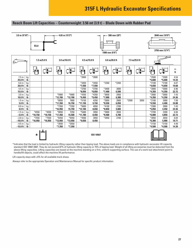
Reach Boom Lift Capacities – Counterweight: 3.56 mt (3.9 t) – Blade Down with Rubber Pad
3.0 m (9'10") 4.65 m (15'3")
1.5 m/5.0 ft
500 mm (20") 3040 mm (10'0")
R3.0
3750 mm (12'4")1990 mm (6'6")
7.5 m 25.0 ft
kg lb
6.0 m 20.0 ft
kg lb
4.5 m 15.0 ft
kg lb
3.0 m 10.0 ft
kg lb
1.5 m 5.0 ft 0.0 m 0.0 ft
kg lb kg lb
*4550 *10,150
*7550 *16,950
–1.5 m –5.0 ft
kg lb
–3.0 m –10.0 ft
kg lb
–4.5 m –15.0 ft
kg lb
*4550 *10,150
*7550 *16,950
3.0 m/10.0 ft
*5900 *12,700
*8050 *17,350
*7350 *16,950
*8050 *17,450
*6450 *13,950
*3550 *7,350
*5900 *12,700
7800 16,750 *7350
15,750 7250
15,500 *6450
*13,950 *3550
*7,350
4.5 m/15.0 ft
*2600
*3450 *7,550 *3700
*8,050 *4350
*9,450 *5150
*11,150 *5600
*12,100 *5400
*11,700 *4500
*9,650
*2600
*3450 *7,550 *3700
*8,050 *4350
*9,450 4250
9,150 4050
8,650 3950
8,450 3950
8,450
ISO 10567
6.0 m/20.0 ft
*2350
*3400 *7,400 *3650
*7,900 *3950
*8,550 *4100
*8,850 *3900
*8,400 *2950
*2350
3000 6,500 2950
6,300 2800
6,050 2700
5,800 2650
5,700 2700
7.5 m/25.0 ft
*2500 2050
m ft
4.54 14.33
6.07 19.68
6.96 22.72
7.43 24.36
7.58 24.88
7.43 24.36
6.94 22.73
6.04 19.71
4.49 14.39
*2500 *2500 *5,600 *5,600 *2100 *2100
*4,650 *4,650 *2000 *2000
*4,350 *4,350 *2000 *2000
*4,350 *4,350 *2100 2000
*4,550 4,400 *2300 2000
*5,050 4,450 *2700 2200
*6,000 4,850 *2850 2650
*6,300 5,900 *2150 *2150
*4,500 *4,500
*Indicates that the load is limited by hydraulic lifting capacity rather than tipping load. The above loads are in compliance with hydraulic excavator lift capacity standard ISO 10567:2007. They do not exceed 87% of hydraulic lifting capacity or 75% of tipping load. Weight of all lifting accessories must be deducted from the above lifting capacities. Lifting capacities are based on the machine standing on a firm, uniform supporting surface. The use of a work tool attachment point to handle/lift objects, could affect the machine lift performance.
Lift capacity stays with ±5% for all available track shoes.
Always refer to the appropriate Operation and Maintenance Manual for specific product information.
27
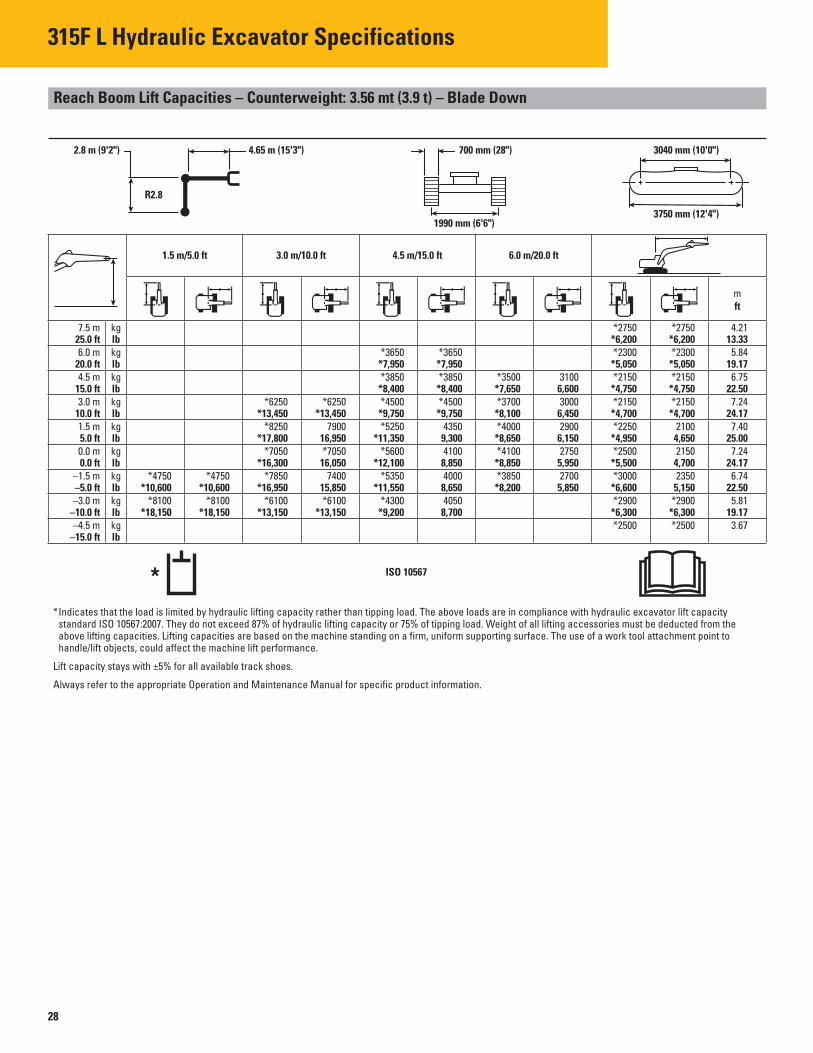
315F L Hydraulic Excavator Specifications
Reach Boom Lift Capacities – Counterweight: 3.56 mt (3.9 t) – Blade Down
2.8 m (9'2") 4.65 m (15'3") 700 mm (28") 3040 mm (10'0")
R2.8
3750 mm (12'4")1990 mm (6'6")
7.5 m kg 25.0 ft lb 6.0 m kg
20.0 ft lb 4.5 m
15.0 ft kg lb
3.0 m 10.0 ft
kg lb
1.5 m 5.0 ft 0.0 m 0.0 ft
kg lb kg lb
–1.5 m –5.0 ft
kg lb
–3.0 m kg –10.0 ft lb –4.5 m kg
–15.0 ft lb
*2750 *2750 *6,200 *6,200
*3650 *3650 *2300 *2300 *7,950 *7,950 *5,050 *5,050 *3850 *3850 *3500 3100 *2150 *2150
*8,400 *8,400 *7,650 6,600 *4,750 *4,750 *6250 *6250 *4500 *4500 *3700 3000 *2150 *2150
*13,450 *13,450 *9,750 *9,750 *8,100 6,450 *4,700 *4,700 *8250 7900 *5250 4350 *4000 2900 *2250 2100
*17,800 16,950 *11,350 9,300 *8,650 6,150 *4,950 4,650 *7050 *7050 *5600 4100 *4100 2750 *2500 2150
*16,300 16,050 *12,100 8,850 *8,850 5,950 *5,500 4,700 *4750 *4750 *7850 7400 *5350 4000 *3850 2700 *3000 2350
*10,600 *10,600 *16,950 15,850 *11,550 8,650 *8,200 5,850 *6,600 5,150 *8100 *8100 *6100 *6100 *4300 4050 *2900 *2900
*18,150 *18,150 *13,150 *13,150 *9,200 8,700 *6,300 *6,300 *2500 *2500
m ft
4.21 13.33
5.84 19.17
6.75 22.50
7.24 24.17
7.40 25.00
7.24 24.17
6.74 22.50 5.81
19.17 3.67
ISO 10567
*Indicates that the load is limited by hydraulic lifting capacity rather than tipping load. The above loads are in compliance with hydraulic excavator lift capacity standard ISO 10567:2007. They do not exceed 87% of hydraulic lifting capacity or 75% of tipping load. Weight of all lifting accessories must be deducted from the above lifting capacities. Lifting capacities are based on the machine standing on a firm, uniform supporting surface. The use of a work tool attachment point to handle/lift objects, could affect the machine lift performance.
Lift capacity stays with ±5% for all available track shoes.
Always refer to the appropriate Operation and Maintenance Manual for specific product information.
1.5 m/5.0 ft 3.0 m/10.0 ft 4.5 m/15.0 ft 6.0 m/20.0 ft
28

315F L Hydraulic Excavator Specifications
Reach Boom Lift Capacities – Counterweight: 3.56 mt (3.9 t) – Blade Down
2.8 m (9'2") 4.65 m (15'3") 600 mm (24") 3040 mm (10'0")
R2.8
3750 mm (12'4")1990 mm (6'6")
7.5 m kg 25.0 ft lb 6.0 m kg
20.0 ft lb 4.5 m
15.0 ft kg lb
3.0 m 10.0 ft
kg lb
1.5 m 5.0 ft 0.0 m 0.0 ft
kg lb kg lb
–1.5 m –5.0 ft
kg lb
–3.0 m kg –10.0 ft lb –4.5 m kg
–15.0 ft lb
*2750 *2750 *6,250 *6,250
*3650 *3650 *2300 *2300 *7,950 *7,950 *5,100 *5,100 *3850 *3850 *3500 3050 *2150 *2150
*8,400 *8,400 *7,650 6,500 *4,750 *4,750 *6300 *6300 *4550 *4550 *3750 2950 *2150 *2150
*13,450 *13,450 *9,800 9,750 *8,100 6,350 *4,750 *4,750 *8300 7850 *5300 4250 *4000 2850 *2250 2100
*17,900 16,850 *11,400 9,200 *8,700 6,100 *4,950 4,600 *7050 *7050 *5650 4050 *4150 2750 *2500 2150
*16,300 15,950 *12,200 8,750 *8,950 5,900 *5,500 4,650 *4750 *4750 *7900 7350 *5400 4000 *3850 2700 *3000 2350
*10,600 *10,600 *17,100 15,800 *11,650 8,550 *8,300 5,800 *6,600 5,100 *8100 *8100 *6200 *6200 *4350 4000 *2900 2850
*18,150 *18,150 *13,300 *13,300 *9,300 8,600 *6,350 6,350 *2550 *2550
m ft
4.21 13.20
5.83 18.88
6.75 22.03
7.24 23.72
7.39 24.26
7.23 23.73
6.73 22.05 5.80
18.91 3.66
ISO 10567
*Indicates that the load is limited by hydraulic lifting capacity rather than tipping load. The above loads are in compliance with hydraulic excavator lift capacity standard ISO 10567:2007. They do not exceed 87% of hydraulic lifting capacity or 75% of tipping load. Weight of all lifting accessories must be deducted from the above lifting capacities. Lifting capacities are based on the machine standing on a firm, uniform supporting surface. The use of a work tool attachment point to handle/lift objects, could affect the machine lift performance.
Lift capacity stays with ±5% for all available track shoes.
Always refer to the appropriate Operation and Maintenance Manual for specific product information.
1.5 m/5.0 ft 3.0 m/10.0 ft 4.5 m/15.0 ft 6.0 m/20.0 ft
29

315F L Hydraulic Excavator Specifications
Power Offset Boom Lift Capacities – Counterweight: 3.56 mt (3.9 t) – Blade Down
2.13 m (6'11") Power Offset Boom 500 mm (20") 3040 mm (10'0")
2.13 m
3750 mm (12'4")1990 mm (6'6")
6.0 m kg 20.0 ft lb 4.5 m kg
15.0 ft lb 3.0 m
10.0 ft kg lb
1.5 m 5.0 ft 0.0 m 0.0 ft
kg lb kg lb
–1.5 m –5.0 ft
kg lb
–3.0 m –10.0 ft
kg lb
3.0 m/10.0 ft
*4550 *10,000
*5000 *10,800
*6600 *14,200
*8050 *17,400
*7850 *17,100
*6700 *14,450
*4450 *9,450
ISO 10567
*Indicates that the load is limited by hydraulic lifting capacity rather than tipping load. The above loads are in compliance with hydraulic excavator lift capacity standard ISO 10567:2007. They do not exceed 87% of hydraulic lifting capacity or 75% of tipping load. Weight of all lifting accessories must be deducted from the above lifting capacities. Lifting capacities are based on the machine standing on a firm, uniform supporting surface. The use of a work tool attachment point to handle/lift objects, could affect the machine lift performance.
Lift capacity stays with ±5% for all available track shoes.
Always refer to the appropriate Operation and Maintenance Manual for specific product information.
1.5 m/5.0 ft
*6300 *6300 *14,050 *14,050
*4550 *10,000
*5000 *10,800
*6600 *14,200
7450 16,050
7050 15,150 *6700
*14,450 *4450
*9,450
4.5 m/15.0 ft
*4150 *9,050 *4600
*10,000 *5150
*11,100 *5250
*11,300 *4650
*10,050
*4150 *9,050
4450 9,600 4100
8,850 3900
8,350 3800
8,200
6.0 m/20.0 ft
*3000 2850
*3850 *8,350 *3750
2700 5,800 2600
*2750 *2750 *6,150 *6,150 *2650 *2650
*5,800 *5,800 *2750 *2750
*6,050 *6,050 *3100 2600
*6,800 5,650 *3750 2600
*8,250 5,700 *3700 3000
*8,100 6,550 *3300 *3300
*7,150 *7,150
m ft
4.21 14.17
5.42 18.33
6.02 20.00
6.21 20.83
6.01 20.00
5.40 18.33
4.17 14.17
30

315F L Hydraulic Excavator Specifications
Work Tool Offering Guide*
Boom Type Reach Boom
Stick Size R3.0 m (9'10") R2.8 m (9'2")
Hydraulic Hammer H110Es H110Es H115Es H115Es
Mobile Scrap and Demolition Shear S320B** S320B**
Compactor (Vibratory Plate) CVP75 CVP75
Contractors’ Grapple G112B G112B
Trash Grapple
Thumbs These work tools are available for the 315F L. Rakes Consult your Cat dealer for proper match. Cat Pin Grabber Coupler
*Matches are dependent on excavator configurations. Consult your Cat dealer for proper work tool match.
**Boom Mount.
31
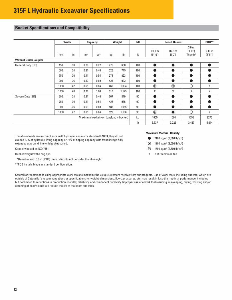
315F L Hydraulic Excavator Specifications
Bucket Specifications and Compatibility
Width Capacity Weight Fill Reach Booms POB**
3.0 m R3.0 m R2.8 m (9'10") 2.13 m
mm in m3 yd3 kg lb % (9'10") (9'2") Thumb* (6'11")
Without Quick Coupler
General Duty (GD)
Severe Duty (SD)
450 18 0.20 0.27 276 608 100
600 24 0.31 0.40 326 719 100
750 30 0.41 0.54 374 823 100
900 36 0.53 0.69 423 932 100
1050 42 0.65 0.84 469 1,034 100 X
1200
600
48 0.76 1.00 510 1,125 100 X X X X
24 0.31 0.40 367 810 90
750 30 0.41 0.54 425 936 90
900 36 0.53 0.69 483 1,065 90
1050 42 0.65 0.84 529 1,166
Maximum load pin-on (payload + bucket)
90
kg
X
1605 1690 1555 2275
lb 3,537 3,725 3,427 5,014
Maximum Material Density: The above loads are in compliance with hydraulic excavator standard EN474, they do not
2100 kg/m3 (3,500 lb/yd3)exceed 87% of hydraulic lifting capacity or 75% of tipping capacity with front linkage fully extended at ground line with bucket curled. 1800 kg/m3 (3,000 lb/yd3)
Capacity based on ISO 7451. 1500 kg/m3 (2,500 lb/yd3)
Bucket weight with Long tips. X Not recommended
*Densities with 3.0 m (9'10") thumb stick do not consider thumb weight.
**POB installs blade as standard configuration.
Caterpillar recommends using appropriate work tools to maximize the value customers receive from our products. Use of work tools, including buckets, which are outside of Caterpillar’s recommendations or specifications for weight, dimensions, flows, pressures, etc. may result in less-than-optimal performance, including but not limited to reductions in production, stability, reliability, and component durability. Improper use of a work tool resulting in sweeping, prying, twisting and/or catching of heavy loads will reduce the life of the boom and stick.
32
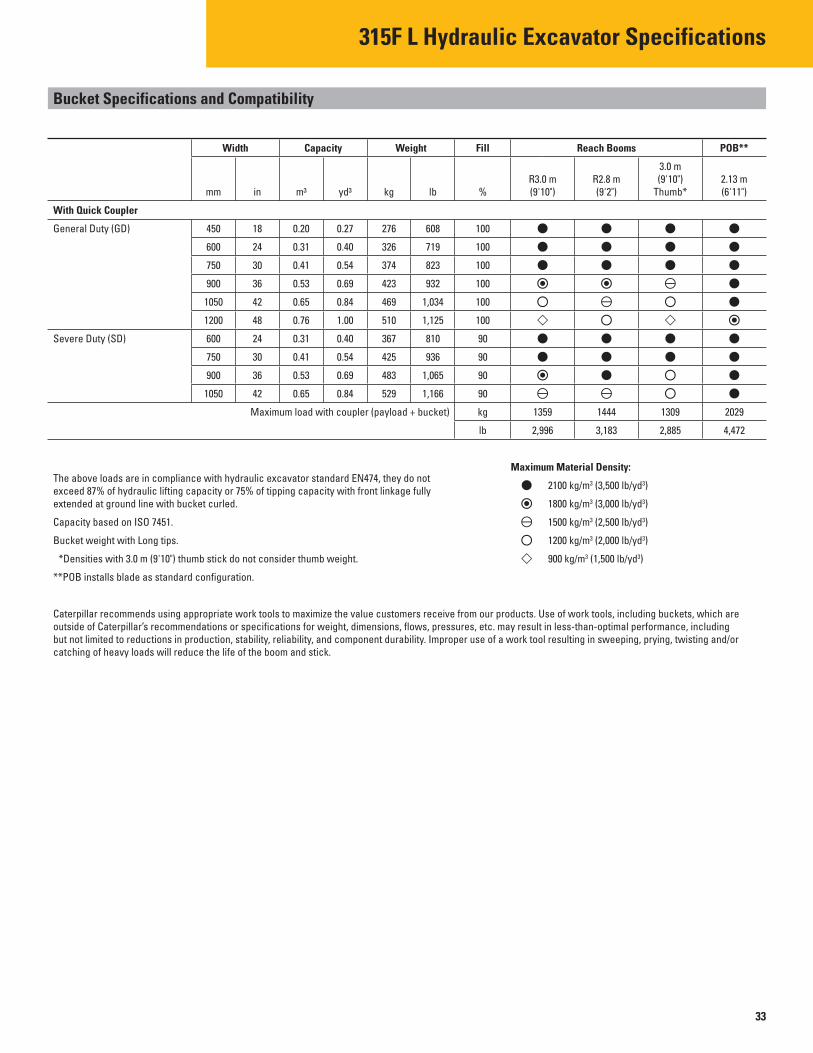
315F L Hydraulic Excavator Specifications
Bucket Specifications and Compatibility
1309
2,885 4,472
Width Capacity Weight Fill
mm in m3 yd3 kg lb %
Reach Booms POB**
3.0 m R3.0 m R2.8 m (9'10") 2.13 m (9'10") (9'2") Thumb* (6'11")
With Quick Coupler
General Duty (GD)
Severe Duty (SD)
1359
450 18 0.20 0.27 276 608 100
600 24 0.31 0.40 326 719 100
750 30 0.41 0.54 374 823 100
900 36 0.53 0.69 423 932 100
1050 42 0.65 0.84 469 1,034 100
1200 48 0.76 1.00 510 1,125 100
600 24 0.31 0.40 367 810 90
750 30 0.41 0.54 425 936 90
900 36 0.53 0.69 483 1,065 90
1050 42 0.65 0.84 529 1,166
Maximum load with coupler (payload + bucket)
90
kg
lb
1444
2,996 3,183
Maximum Material Density: The above loads are in compliance with hydraulic excavator standard EN474, they do not
2100 kg/m3 (3,500 lb/yd3)exceed 87% of hydraulic lifting capacity or 75% of tipping capacity with front linkage fully extended at ground line with bucket curled. 1800 kg/m3 (3,000 lb/yd3)
Capacity based on ISO 7451. 1500 kg/m3 (2,500 lb/yd3)
Bucket weight with Long tips. 1200 kg/m3 (2,000 lb/yd3)
*Densities with 3.0 m (9'10") thumb stick do not consider thumb weight. 900 kg/m3 (1,500 lb/yd3)
**POB installs blade as standard configuration.
Caterpillar recommends using appropriate work tools to maximize the value customers receive from our products. Use of work tools, including buckets, which are outside of Caterpillar’s recommendations or specifications for weight, dimensions, flows, pressures, etc. may result in less-than-optimal performance, including but not limited to reductions in production, stability, reliability, and component durability. Improper use of a work tool resulting in sweeping, prying, twisting and/or catching of heavy loads will reduce the life of the boom and stick.
33
2029
315F L Standard Equipment
Standard Equipment
Standard equipment may vary. Consult your Cat dealer for details.
CAB
• Pressurized operator station with positive fi ltration
• Sliding upper door window (left-hand cab door)
• Removable lower windshield with in cab storage bracket
• Coat hook • Beverage holder • Literature holder • AM/FM radio • Radio with MP3 auxiliary audio port • Two stereo speakers • Storage shelf suitable for lunch or toolbox • Color LCD display with indicators,
fi lter/fluid change, and working hour information
• Adjustable armrest • Height adjustable joystick consoles • Neutral lever (lock out) for all controls • Travel control pedals with
removable hand levers • Capability of installing additional pedal • Power outlets, 5 amp • Travel alarm • Laminated glass front upper window
and tempered other windows
ELECTRICAL
• 80 amp alternator • Circuit breaker • Capability to electrically connect a beacon
ENGINE
• C4.4 ACERT diesel engine • Biodiesel capable • Meets Tier 4 Final emission standards • 2300 m (7,500 ft) altitude capability • Electric priming pump • Automatic engine speed control • Economy and high power modes • Two-speed travel • Side-by-side cooling system • Radial seal air fi lter • Primary filter with water separator
and water separator indicator • Secondary fi lter • Screen filter in fuel line • Variable speed fan with viscous clutch
HYDRAULIC SYSTEM
• Boom drift reduction valve • Regeneration circuit for boom and stick • Reverse swing dampening valve • Automatic swing parking brake • High-performance hydraulic return fi lter • Fine swing control
LIGHTS
• Halogen boom light (left side) • Time delay function for boom light
and cab light • Exterior light
UNDERCARRIAGE
• Center track guiding guard • Grease Lubricated Track GLT2, resin seal • Towing eye on base frame
SECURITY
• Cat one key security system • Door locks • Cap locks on fuel and hydraulic tanks • Lockable external tool/storage box • Signaling/warning horn • Secondary engine shutoff switch • Rear window for emergency exit • Guard, travel motor protection • Rearview camera
TECHNOLOGY
• Product Link
34