larkin final - larkin industries, inc.larkinhoods.com/kitchen_ventilation_catalog.pdfwelcome to...
TRANSCRIPT
� � � � � � � � � � � � � � � � � � � � � � � � � � � � � � � � � � � � � � � � � � �
� � � � � � � � � � � � � � �� � � � � � ! ! � " � #
1
WELCOME TO LARKIN INDUSTRIES, INC.
Congratulations!!! You have received one of the most comprehensive and user friendly
kitchen ventilation catalogs that is in use today.
Our hope is that you are involved in some phase of the kitchen hood and kitchen
ventilation package. Whether you are a member of the design team or the installation
team, we hope that this catalog is of help when questions arise about the function and
performance of the kitchen ventilation system.
This information can be helpful when selecting hood models, determining air flow, static
pressure at the exhaust or supply duct collars, and required overhang. It also offers other
information necessary to properly design a kitchen ventilation system.
If you have any questions about our catalog or if you have any questions about kitchen
ventilation systems, please call our customer service department at 1-800-322-4036. You
may also contact our customer service department via the fax, at (205) 987-0583, via
email - [email protected], or visit us on the web at www.larkinhoods.com.
We hope that our catalog becomes a valuable tool as you begin the design work on your
next kitchen ventilation system.
Thank you in advance for using Larkin Industries, Inc.
© 2010 Larkin Industries, Inc.
2
1. COMPLETE, DETAILED SUBMITTAL DRAWINGS
2. SHOP DRAWINGS SHOWING COLLAR LOCATIONS, ETC
3. FULL PRINT SIZE C.A.D DRAWINGS
4. STANDARD LEAD TIME OF APPROXIMATELY TWO WEEKS
5. 6 DAY EXPRESS SHIPPING PROGRAM (OPTIONAL)
6. 3 DAY SUPER EXPRESS SHIPPING PROGRAM (OPTIONAL)
7. COMPUTERIZED, WRITTEN QUOTES
8. WRITTEN QUOTES ARE FULL FREIGHT ALLOWED
9. THE ONLY “HASSLE FREE” FAN MOTOR WARRANTY IN THE INDUSTRY
10. FREIGHT/SHIPMENT TRACKING SERVICES
11. OVER TWO HUNDRED EXHAUST FANS IN STOCK
12. ELEVEN SUPPLY FAN MODELS AVAILABLE FOR IMMEDIATE SHIPMENT
13. FAN AND KITCHEN HOOD INSTALLATION INSTRUCTIONS
14. OPERATION AND MAINTENANCE INSTRUCTIONS
15. ENGINEERING DESIGN ASSISTANCE
16. FULLY STAFFED, PROFESSIONAL CUSTOMER SERVICE DEPARTMENT
SERVICES OFFERED BY LARKIN INDUSTRIES, INC.
TOLL FREE NUMBER - 800-322-4036
FAX - (205) 987-0583
EMAIL - [email protected]
WWW.LARKINHOODS.COM
© 2010 Larkin Industries, Inc.
3© 2010 Larkin Industries, Inc.
Larkin Industries, Inc.114 David Green RoadBirmingham, AL 35244Phone: 1-205-987-1535Fax: 1-205-987-0583Toll Free: 1-800-322-4036E-mail: [email protected]
4 © 2010 Larkin Industries, Inc.
Table of Contents
• Glossary of Terms . . . . . . . . . . . . . . . . . . . . . . . . . . . . . . . . . . . . . . . . . . . . . . . . . pg 6
• Introduction to Kitchen Ventilation Design . . . . . . . . . . . . . . . . . . . . . . . . . . . . . . . pg 8
• Leading Exhaust Only Hood Models . . . . . . . . . . . . . . . . . . . . . . . . . . . . . . . . . . . . . pg 12
• Leading Self Compensating Hood Models . . . . . . . . . . . . . . . . . . . . . . . . . . . . . . . . pg 18
• Leading Compensating Hood Models . . . . . . . . . . . . . . . . . . . . . . . . . . . . . . . . . . . . pg 23
• Other Self Compensating Hood Models . . . . . . . . . . . . . . . . . . . . . . . . . . . . . . . . . . pg 28
• Other Compensating Hood Models . . . . . . . . . . . . . . . . . . . . . . . . . . . . . . . . . . . . . . pg 29
• Low Ceiling Hood Models . . . . . . . . . . . . . . . . . . . . . . . . . . . . . . . . . . . . . . . . . . . . pg 31
• Low Proximity Hood Models . . . . . . . . . . . . . . . . . . . . . . . . . . . . . . . . . . . . . . . . . . pg 32
• Back Shelf Hood Models . . . . . . . . . . . . . . . . . . . . . . . . . . . . . . . . . . . . . . . . . . . . . pg 34
• Oven and Condensate Hood Models . . . . . . . . . . . . . . . . . . . . . . . . . . . . . . . . . . . . . pg 36
• Fan Selection Guide . . . . . . . . . . . . . . . . . . . . . . . . . . . . . . . . . . . . . . . . . . . . . . . . pg 39
• Exhaust and Supply Air Static Pressure and Collar Sizing Charts . . . . . . . . . . . . . . . . pg 40
• Hood Filter Configuration Charts . . . . . . . . . . . . . . . . . . . . . . . . . . . . . . . . . . . . . . pg 45
• Hood Weights . . . . . . . . . . . . . . . . . . . . . . . . . . . . . . . . . . . . . . . . . . . . . . . . . . . . pg 47
• Hanger Location Drawings . . . . . . . . . . . . . . . . . . . . . . . . . . . . . . . . . . . . . . . . . . . pg 48
• Exhaust Fans . . . . . . . . . . . . . . . . . . . . . . . . . . . . . . . . . . . . . . . . . . . . . . . . . . . . . pg 49
• Supply Fans . . . . . . . . . . . . . . . . . . . . . . . . . . . . . . . . . . . . . . . . . . . . . . . . . . . . . pg 57
• Heated Roof Top Packages . . . . . . . . . . . . . . . . . . . . . . . . . . . . . . . . . . . . . . . . . . . pg 64
• Un-tempered Roof Top Packages . . . . . . . . . . . . . . . . . . . . . . . . . . . . . . . . . . . . . . . pg 66
• Available Options . . . . . . . . . . . . . . . . . . . . . . . . . . . . . . . . . . . . . . . . . . . . . . . . . pg 69
• Installation, Start-up and Maintenance . . . . . . . . . . . . . . . . . . . . . . . . . . . . . . . . . . pg 97
5© 2010 Larkin Industries, Inc.
Terms and Conditions
Shipping Schedules: Super Express (3 working days), Express (6 working days), or 2 weeks normal leadtimes. (Some restrictions may apply)
Additions: Additions to an order will be accepted if made on the same day the order is received. (There maybe an extra charge if made after the order is in production).
Freight Allowance: All shipments, unless otherwise noted, are Freight Allowed. Shipments will be F.O.B.Factory and shipped via truck line of Larkin Industries, Inc. choice. (We pay Freight)
Confirmation: Some orders may be subject to confirmation (a signed acknowledgement required) or will besubject to withheld shipment. Larkin Industries, Inc. will not accept responsibility for errors of any kind onverbal orders unless a written confirmation is received within 24 hours of the order.
Credit Terms: In order to facilitate immediate shipment, Larkin Industries, Inc. accepts all major credit cards:Visa, MasterCard, American Express and Discover. You may remit payment with the order by an approvedmethod. No C.O.D. orders accepted without prior approval. Shipment will be made Net 30 on open accountto those concerns who have established credit with Larkin Industries, Inc. or who are satisfactorily rated incommercial reference books. If, in our opinion, the financial status of the buyer warrants such action, wereserve the right at any time, on any unshipped order or portion thereof to alter, withdraw or otherwise fix thelimits of credit extended, or to require cash payment in advance. A service charge at the legal rate per annumwill be assessed on all accounts 30 days or more past due.
Cancellation: Orders may be cancelled upon approval by Larkin Industries, Inc. and will be subject to aminimum of $50.00 plus charge of materials consumed and work performed up to the date of cancellation.Larkin Industries, Inc. reserves the right to cancel any order at anytime in the event of fire, strike, inclementweather, act of God, or other good cause. In such an event, Larkin Industries, Inc. liability for any such actionshall be limited to the refund of any payment by the purchaser.
Returned Merchandise: No merchandise may be returned for credit without our written permission andshipping instructions. Larkin Industries, Inc. will not accept the return of items made to order, or any item ofunsaleable class or size. All items authorized for return must be in a new and resalable condition. On standarditems accepted for credit, a charge determined after return (up to 100%) will be made to cover the cost ofhandling, inspecting, and repackaging. Transportation charges allowed or paid by Larkin Industries, Inc. onoutgoing shipments will also be deducted From credit issued. Return transportation charges must be prepaid.
Responsibility: Larkin Industries, Inc. cannot assume responsibility for loss or damage to goods in transit,or for delays of carrier receipts for the shipment in good order. However, when goods are lost or damaged intransit, we will assist in every way possible. In case of shortage or apparent damage, details should be notedby the carrier’s agent on the freight or express bill before accepting delivery. Any damaged pieces of freightmust be refused and will be returned to Larkin Industries, Inc. for repair or replacement. Any discrepancy inquantity, size, model, or pricing must be reported to Larkin Industries, Inc. within 15 days after shipment. Incase of concealed damage, carrier should immediately be called in to inspect the package and damaged goods.
All prices are subject to change without notice.
* All transactions with Larkin Industries, Inc. are subject to the full terms and conditions of Larkin Industries, Inc. A detailed copy isavailable upon request.
6 © 2010 Larkin Industries, Inc.
Glossary of Terms
Air, Make-Up or (Supply Air) - Air required to replaceor make-up air that is exhausted in a building. Also, fromNFPA-96; air deliberately brought into the structure, thenspecifically directed to the vicinity of a mechanically orthermally forced exhausting device for the purpose ofcompensating for the air or gases being expelled.
CFM - Cubic feet per minute. Most air flow design data ismeasured in cfm. The volume of air moved per minute.
Duct - A passageway made of sheet metal (usually exhaustduct is made from 16-gauge black iron) or suitable materi-al, used for conveying air or other gas at low pressures.
Duct Velocity - Air speed through the (exhaust duct). The rate of motion. NOTE: NFPA-96, 8.2.1.1 states that theair velocity through any exhaust duct shall not be less than500 FPM.
Face Velocity - The velocity obtained by dividing the airquantity by the component face area.
FPM - Feet per minute. (Velocity of Air) Volume (cfm) Area (in Sq. Ft.)
Fan Centrifugul - A fan rotor or wheel within a scroll-typehousing and including driving mechanism supports foreither belt drive or direct drive.
Free Air Delivery - The conditions existing when thereare no effective restrictions to air flow. No measurablestatic pressure.
Full-Load Amps - Line current (amperage drawn by amotor when operating at rated load and voltage.)
Liquid-Tight - Constructed and performing in such amanner as not to permit the passage of any liquid at a giventemperature and pressure.
Outlet Velocity - The average velocity of air emergingfrom an opening, fan, or outlet measured in the plane ofthe opening.
Pressure Drop - Pressure loss in fluid pressure, as fromone end of a duct to the other, duct friction, dynamiclosses, and changes in velocity pressure.
RPM - Revolutions per minute. The speed at which theshaft or motor of an air moving device is rotating.
Sones - A subjective unit of loudness. The loudness of anexhaust fan is measured in sones. Kitchen exhaust above18 sones could spell trouble.
Starting Amps - The surge of amperage needed to start aparticular electrical device.
Static Pressure - This is an important term to understand.A measure of the resistance to movement of forced airthrough a system caused by ductwork, inlets, louvers, fil-ters, etc. Measured in inches of water gauge (wg.).
Resistance to Air Flow - Resistance to air flow fromductwork, filters, dampers, louvers, etc. will increase staticpressure and decrease volume (CFM).
Thermal Protector - A temperature-sensing device builtinto the motor that disconnects the motor from its powersource if the temperature becomes excessive.
Type I Hoods - Hoods used over smoke and grease pro-ducing equipment. This type hood should be equiped withbaffle type grease filters.
Type II Hoods - Hoods used over non-grease or smokeproducing equipment where heat or steam removal isrequired.
Updraft - The upward movement of air due to a changein density. Remember, one of the reasons for a six-inchoverhang is that air expands as it is heated.
Velocity - A vector (a quantity which requires a directionto be stated in order to define it) quantity which denotes,at once, the time rate and the direction of a linear (straight)motion: in other words, the quickness of something.
Pantleg Ductwork - Used on end-to-end hoods or hoodswith two duct collars to connect the two collars to a singleduct.
= FPM
Radiant Heat and Kitchen Ventilation
No doubt you have often heard a chef complaining about a hot kitchen. It is a common complaint and usually it is thekitchen hood that gets singled out as the primary cause for discomfort. However, in most cases, it is not a malfunctioninghood at fault but the forces of “radiant heat”. Cooking equipment produces two types of heat, radiant and convected.Convected heat is defined as air in contact with a hot surface which absorbs the heat from that surface, expands and rises,thus conveying the heat with it. In a kitchen, convected heat comes off the cooking surface and is carried up intothe exhaust hood by the thermal air currents and by the air being pulled across the cooking equipment. If the hood isoperating properly, all of the convected heat will be exhausted. Radiant heat as defined by the Ashrae Handbook, is thetransmission of heat through space by wave motion from one object to another without warming the space between. Unlikeconvected heat, radiant heat comes off the cooking surface at all different angles, some bouncing off the back wall and thehood’s surfaces. Radiant heat always travels in a straight line and will not change direction until it hits a solid object. Sincethe chef is normally standing in front of the equipment he receives the full effect of this radiant heat. The air being drawnacross the cooking equipment and up into the hood will not reduce the amount of radiant heat regardless of how fast theair is moving. As radiant heat strikes an object, that object will produce convected heat which, in turn, affects thetemperature of the room. Thus, radiant heat indirectly heats the air in a kitchen. By first transferring the heat fromthe cooking equipment directly to the chef and then by helping to produce additional convected heat. Radiant heat is theprimary cause for the uncomfortable environment in which a chef must work.
A simple test can be used to demonstrate the effect of radiant heat. With a chef standing in front of a hot range, hold athermometer at chest level and record the reading. Now place a large piece of cardboard between the chef and the range.You will notice the chef will feel much cooler. Put the thermometer between the chef and the cardboard and you will findthat the temperature has not changed. While the temperature of the air around the chef has not been altered, the chef feelscooler because the cardboard has effectively stopped the radiant heat being supplied by the cooking equipment.
In summary, keeping a chef comfortable in a kitchen environment is a difficult task. Independent studies show that toprovide a totally comfortable environment for a chef standing continuously in front of a hot range, air temperatures of below0° F would be needed for his face, 32° F for his waist and 70° F for his legs.
There are, however, a few simple things that can be done to help reduce the effects of radiant heat.
1. Keep the cooking equipment turned down as low as possible when not in use.
2. For cooking appliances such as ranges, hot tops, open burners, etc., put pans of water on the range top. This will absorb a considerable amount of radiant heat by changing it to latent heat (moisture) which, in turn, is drawn up by the hood.
3. By wearing white clothing, some of the radiant heat will be reflected.
Interesting Facts on Radiant Heat
1. Radiant heat can constitute up to 90% of the internal heat load in a kitchen.
2. Radiant heat wastes 8% to 15% of the total energy consumed by the restaurant.
3. Radiant heat equals 20% to 35% of the actual energy input to the cooking equipment.
7© 2010 Larkin Industries, Inc.
Introduction to Ventilation Design
Kitchen ventiliation design can be very complex. There are many competing formulas and theories on the best way to designa properly functioning kitchen ventilation system. ASHRAE has recently conducted the most comprehensive study to date.The formulas are complex and do not necessarily represent each manufacturer’s specific models and their performance inactual field conditions.
The kitchen ventilation industry and code authorities have combined the results of extensive laboratory testing and actualfield experience to shorten and simplify these formulas.
Most code authorities require air flow rates based on the worst condition cooking loads and type of cooking appliancesunless they are listed by a nationally recognized testing authority such as Electrical Testing Laboratory (ETL) or UnderwritersLaboratory (UL). Larkin Industries ETL listed air flow data allows the designer to use air flows lower than the InternationalMechanical Code and NFPA-96 requires. Note: Larkin Industries often recommends air flows that exceeds their ETL listed airflow data to allow for actual field conditions.
ETL and UL listings are frequently misunderstood by hood designers and code authorities. ETL & UL certifies that a particularhood is built to NFPA 96 Standards, meets the National Electrical code NFPA 70, and is inspected, tested and evaluated tothe standards found in Exhaust Hoods for Commercial Cooking Equipment ANSI/UL 710. All hoods are tested under controlledlaboratory conditions. The guidelines for these tests are as follows: hoods are tested with only one piece of equipment underthe hood, a griddle at 450° F and a charbroiler at 600° & 700° F also laboratory air pressure, temperature, humidity, sizeof laboratory, fat content of meat, and drafts are all controlled. The air flow rates are established when all the smoke isremoved by the hood and this is determined by a visual inspection.
Larkin Industries, Inc. factory recommendations may differ from actual test data, to allow for field conditions such as crossdrafts, inadequate overhangs, dirty filters, loose fan belts, pass-through windows on back of hood, hood hung higher thanspecified, heavy cooking loads on ends of hood (without overhang allowance), longer-than- expected or re-routed ductwork,non radius elbows, header duct systems instead of pant leg, overloading cooking equipment during peak operation (such ascharbroilers and griddles with high fat content foods), personnel movement about the space causing drafts, outside doorsopening adjacent to hoods during cooking operation, system not properly balanced, etc. As you can see, all these and otherproblems are commonplace in actual field conditions, and are not involved during ETL and UL testing. Most all factoriespublish their ETL and UL test data, for engineers and designers; please exercise caution when using Larkin Industries, Inc.or any factory’s ETL and UL test data. We recommend a 10 to 25 percent safety factor be added after the total job’s CFM areobtained, to allow for probable field conditions. Remember there is nothing worse than an installed kitchen ventilationsystem that does not work properly!
8 © 2010 Larkin Industries, Inc.
**The following pages are the data obtained from our years of ETL and UL testing.
Ventilation System Design Guide
When designing a kitchen ventilation system the following information must be known:
1. What type of hood is desired?2. Will a wall or island hood be needed?3. What size kitchen hood is needed (after the overhang is added)?4. What load (smoke and grease vapors) at what temperature?5. Is make-up air required and how much from the hood?
The following ETL test data, static pressure charts, and collar sizing information should help you select a Larkin system tomeet your design requirements. If any assistance is needed, consult Larkin Industries, Inc. Our staff will be glad to assistyou at 1-800-322-4036.
The exhaust and supply CFM are determined by the hood length and cooking load.
• Light-Medium load (steamers, kettles, ovens, griddles, fryers, open burner ranges) up to 450° F cookingtemperature.
• Heavy load (charbroilers (gas and electric), salamanders, upright broilers, wok) up to 600° F cookingtemperature.
• Extra-Heavy load (charcoal broilers, mesquite grills, gas conveyor charbroilers) up to 700° F cookingtemperature.
NOTE: If a mixture of equipment is used under one hood, it is recommended to define the cooking load to the next highestload or use separate hoods.
Example: With one oven, one range, two fryers, and one griddle at 45O° F, and a charbroiler at 6O0° F, a heavy load shouldbe selected.
The recommended CFM per linear foot and overhangs for the above cooking loads per models are found inthe following pages.
Example: A SC model wall style hood with a light load (450° F cooking surface temperature) is 258 CFM per linear footexhaust and 207 CFM supply with a 6” side overhang. If the equipment is 12’ in length + a 6” overhang for each side = a13’ hood x 207 CFM per linear foot supply = 2691 CFM of supply air. Add a 10% safety factor for actual field condition; thiswill give you 3689 CFM of exhaust air. Exhaust and supply static pressures, collar sizes and collar velocities are found onthe collar sizing pages 40-44.
9© 2010 Larkin Industries, Inc.
Hood Selection Procedures
Step No. 1: Determine the overall length, depth and location of cooking bank.
Step No. 2: Determine the type of appliances: griddles, fryers, broilers, ovens, etc.
Step No. 3: Select basic type:Wall (cooking bank is against wall), Island (cooking bank is in middle of room); Double Island (cooking banksare back to back)
Step No. 4: Select style:(Exhaust-only hoods) This hood is generally used in a non air-conditioned kitchen.(Compensating hood) The volume and direction of the make-up air can be adjusted at the hood.The make-up air may require tempering.(Self-compensating) This hood requires no tempering of make-up air. See hood styles section for specific hoodstyle and model #.
Step No. 5: Select size:The overhead canopy-type hood should be sized to completely cover the equipment that it is designed toventilate, plus an overhang of at least 6” to 12” on all sides of equipment not immediately adjacent to wallsor other construction extending above the cooking surface. Island-type hoods over one cooking bank shouldhave 10” to 12” overhang at back of cooking bank. See hood styles section for standard hood sizes. Somelocal fire codes will require 12” overhang on any hood, and some health codes require a minimum distancefrom walls or between banks of cooking equipment of 6” to 12” to provide for cleaning. Check your local codes.
Step No. 6: Select volume of exhaust air:Most codes require exhaust air selection based on type of cooking appliances, unless it is a listed hood.NOTE: Larkin hoods have been tested and approved by ETL to capture vapors from cooking equipment atless than International Mechanical Code requires. Check air-flow data pages for specific modelsair-flow requirements.
Step No. 7: Select exhaust duct required:Larkin Industries recommends exhaust duct be sized between 1500-1800 FPM. NFPA requires a minimumvelocity of at least 500 FPM. Hoods 10’ or more in length may require two ducts. Keep duct size as square aspossible. Consult your local codes for fire wraping requirements.
Step No. 8: Exhaust and supply fans should be selected with adjustable pulleys so that air can be adjusted to arrive at aproper differential of exhaust and supply air. Fans should be selected according to model of hood selected andcooking loads. Generally an exhaust and supply differential of 70% to 95% is selected. Some codes require aset exhaust differential up to 100%. Consult your local codes.
Design Statement
There are many factors to consider when selecting the proper kitchen hood system, such as: type and amount of cookingequipment under the hood, restaurant HVAC system design, outside air requirement, ductwork sizes and length-of-duct run,state and local fire, health and building codes; so please check with the local codes and or a registered mechanical engineerin your area when determining the style and CFM requirements for a specific kitchen hood system installation.
10 © 2010 Larkin Industries, Inc.
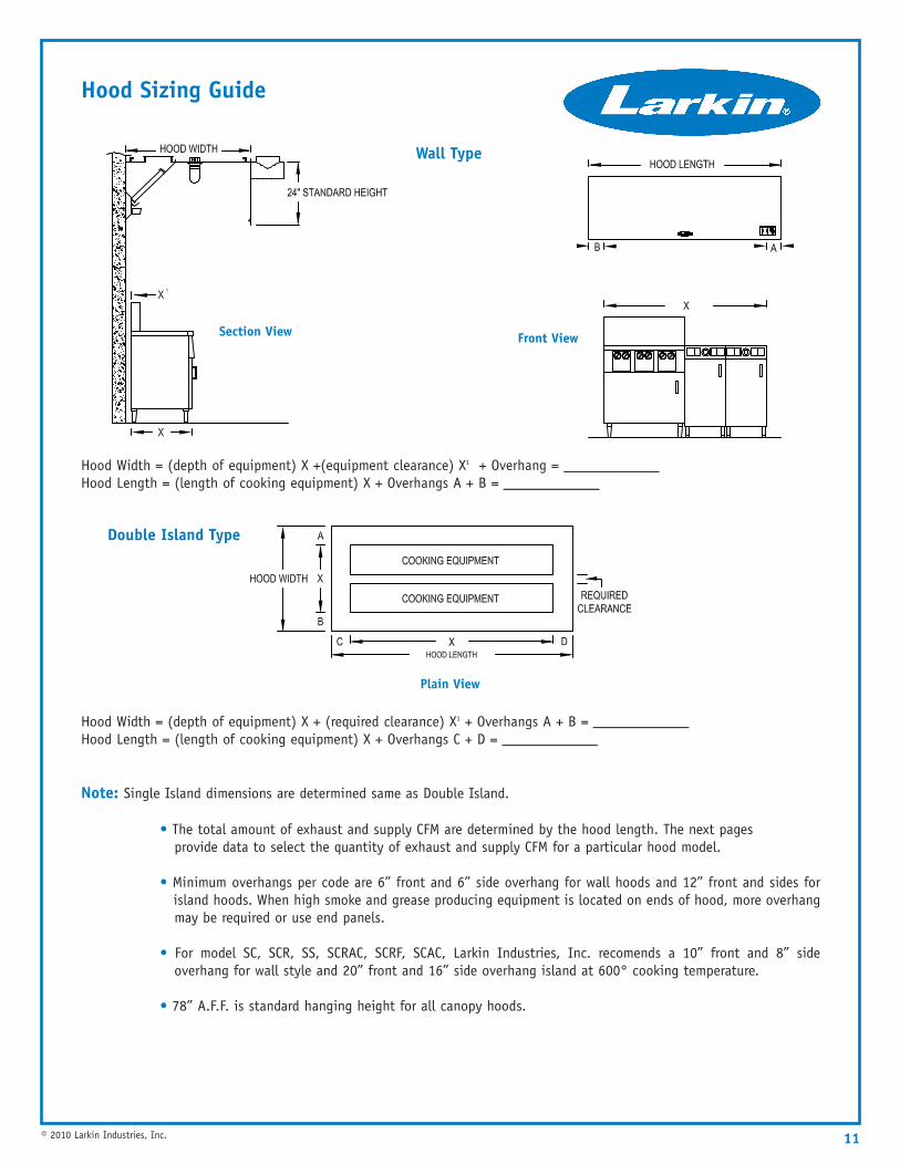
Hood Sizing Guide
Hood Width = (depth of equipment) X + (required clearance) X1 + Overhangs A + B = _____________Hood Length = (length of cooking equipment) X + Overhangs C + D = _____________
Note: Single Island dimensions are determined same as Double Island.
• The total amount of exhaust and supply CFM are determined by the hood length. The next pages provide data to select the quantity of exhaust and supply CFM for a particular hood model.
• Minimum overhangs per code are 6” front and 6” side overhang for wall hoods and 12” front and sides forisland hoods. When high smoke and grease producing equipment is located on ends of hood, more overhangmay be required or use end panels.
• For model SC, SCR, SS, SCRAC, SCRF, SCAC, Larkin Industries, Inc. recomends a 10” front and 8” sideoverhang for wall style and 20” front and 16” side overhang island at 600° cooking temperature.
• 78” A.F.F. is standard hanging height for all canopy hoods.
Hood Width = (depth of equipment) X +(equipment clearance) X1 + Overhang = _____________Hood Length = (length of cooking equipment) X + Overhangs A + B = _____________
11© 2010 Larkin Industries, Inc.
Section View
Wall Type
Front View
Double Island Type
Plain View
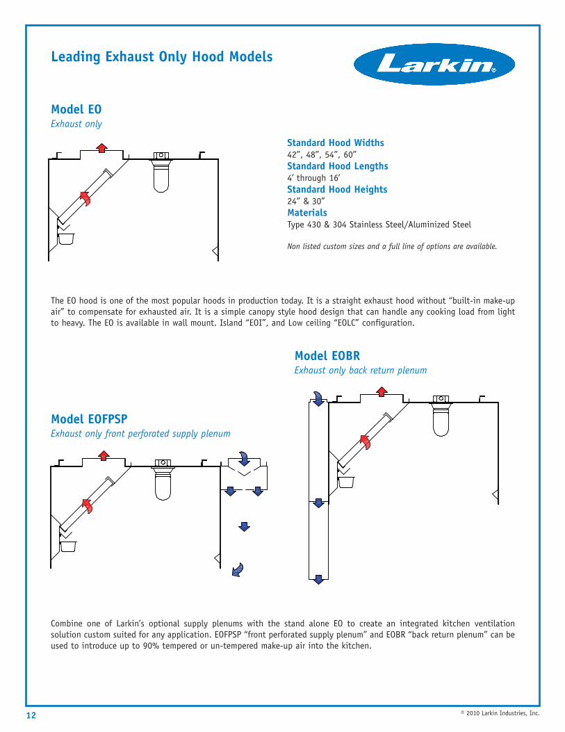
Leading Exhaust Only Hood Models
Model EO Exhaust only
The EO hood is one of the most popular hoods in production today. It is a straight exhaust hood without “built-in make-upair” to compensate for exhausted air. It is a simple canopy style hood design that can handle any cooking load from lightto heavy. The EO is available in wall mount. Island “EOI”, and Low ceiling “EOLC” configuration.
Model EOFPSP Exhaust only front perforated supply plenum
Model EOBR Exhaust only back return plenum
Combine one of Larkin’s optional supply plenums with the stand alone EO to create an integrated kitchen ventilationsolution custom suited for any application. EOFPSP “front perforated supply plenum” and EOBR “back return plenum” can beused to introduce up to 90% tempered or un-tempered make-up air into the kitchen.
Standard Hood Widths42”, 48”, 54”, 60”Standard Hood Lengths4’ through 16’Standard Hood Heights24” & 30”MaterialsType 430 & 304 Stainless Steel/Aluminized Steel
Non listed custom sizes and a full line of options are available.
12 © 2010 Larkin Industries, Inc.
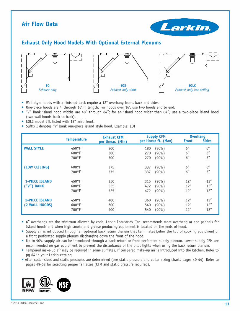
Air Flow Data
Exhaust Only Hood Models With Optional External Plenums
• Wall style hoods with a finished back require a 12” overhang front, back and sides.• One-piece hoods are 4’ through 16’ in length. For hoods over 16’, use two hoods end to end.• “V” Bank island hood widths are 48” through 84”; for an island hood wider than 84”, use a two-piece island hood
(two wall hoods back to back).• EOLC model ETL listed with 12” min. front.• Suffix I denotes “V” bank one-piece island style hood. Example: EOI
• 6” overhangs are the minimum allowed by code. Larkin Industries, Inc. recommends more overhang or end pannels forIsland hoods and when high smoke and grease producing equipment is located on the ends of hood.
• Supply air is introduced through an optional back return plenum that terminates below the top of cooking equipment ora front perforated supply plenum discharging down the front of the hood.
• Up to 90% supply air can be introduced through a back return or front perforated supply plenum. Lower supply CFM arerecommended on gas equipment to prevent the disturbance of the pilot lights when using the back return plenum.
• Tempered make-up air may be required in some climates, if tempered make-up air is introduced into the kitchen. Refer topg 64 in your Larkin catalog.
• After collar sizes and static pressures are determined (see static pressure and collar sizing charts pages 40-44). Refer topages 49-68 for selecting proper fan sizes (CFM and static pressure required).
13© 2010 Larkin Industries, Inc.
Temperature Exhaust CFM per linear. (Min)
Supply CFM per linear ft. (Max)
Overhang Front Sides
WALL STYLE
(LOW CEILING)
1-PIECE ISLAND (“V”) BANK
2-PIECE ISLAND (2 WALL HOODS)
450°F 200 180 (90%) 6” 6”600°F 300 270 (90%) 6” 6”700°F 300 270 (90%) 6” 6”
600°F 375 337 (90%) 6” 6”700°F 375 337 (90%) 6” 6”
450°F 350 315 (90%) 12” 12”600°F 525 472 (90%) 12” 12”700°F 525 472 (90%) 12” 12”
450°F 400 360 (90%) 12” 12”600°F 600 540 (90%) 12” 12”700°F 600 540 (90%) 12” 12”
EOSExhaust only slant
EOLCExhaust only low ceiling
EOExhaust only
14
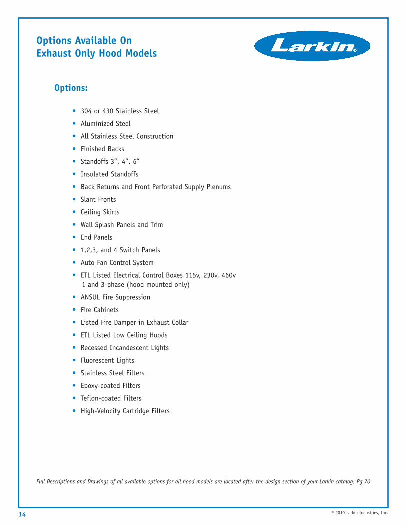
Options Available On Exhaust Only Hood Models
© 2010 Larkin Industries, Inc.
Options:
• 304 or 430 Stainless Steel
• Aluminized Steel
• All Stainless Steel Construction
• Finished Backs
• Standoffs 3”, 4”, 6”
• Insulated Standoffs
• Back Returns and Front Perforated Supply Plenums
• Slant Fronts
• Ceiling Skirts
• Wall Splash Panels and Trim
• End Panels
• 1,2,3, and 4 Switch Panels
• Auto Fan Control System
• ETL Listed Electrical Control Boxes 115v, 230v, 460v1 and 3-phase (hood mounted only)
• ANSUL Fire Suppression
• Fire Cabinets
• Listed Fire Damper in Exhaust Collar
• ETL Listed Low Ceiling Hoods
• Recessed Incandescent Lights
• Fluorescent Lights
• Stainless Steel Filters
• Epoxy-coated Filters
• Teflon-coated Filters
• High-Velocity Cartridge Filters
Full Descriptions and Drawings of all available options for all hood models are located after the design section of your Larkin catalog. Pg 70
15© 2010 Larkin Industries, Inc.
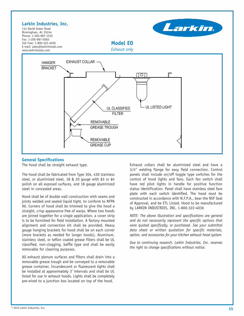
General SpecificationsThe hood shall be straight exhaust type.
The hood shall be fabricated from Type 304, 430 stainlesssteel, or aluminized steel. 18 & 20 gauge with #3 or #4polish on all exposed surfaces, and 18 gauge aluminizedsteel in concealed areas.
Hood shall be of double wall construction with seams andjoints welded and sealed liquid tight, to conform to NFPA96. Corners of hood shall be trimmed to give the hood astraight, crisp appearance free of warps. Where two hoodsare joined together for a single application, a cover stripis to be furnished for field installation. A factory mountedalignment and connection kit shall be provided. Heavygauge hanging brackets for hood shall be on each corner(more brackets as needed for longer hoods). Aluminum,stainless steel, or teflon coated grease filters shall be ULclassified, non-clogging, baffle type and shall be easilyremovable for cleaning purposes.
All exhaust plenum surfaces and filters shall drain into aremovable grease trough and be conveyed to a removablegrease container. Incandescent or fluorescent lights shallbe installed at approximately 3’ intervals and shall be ULlisted for use in exhaust hoods. Lights shall be completelypre-wired to a junction box located on top of the hood.
Exhaust collars shall be aluminized steel and have a3/4” welding flange for easy field connection. Controlpanels shall include on/off toggle type switches for thecontrol of hood lights and fans. Each fan switch shallhave red pilot lights in handle for positive functionstatus identification. Panel shall have stainless steel faceplate with each switch identified. The hood must beconstructed in accordance with N.F.P.A., bear the NSF Sealof Approval, and be ETL Listed. Hood to be manufacturedby LARKIN INDUSTRIES, INC. 1-800-322-4036
NOTE: The above illustration and specifications are generaland do not necessarily represent the specific options thatwere quoted specifically, or purchased. See your submittaldata sheet or written quotation for specific materials,option, and accessories for your kitchen exhaust hood system.
Due to continuing research, Larkin Industries, Inc. reservesthe right to change specifications without notice.
Model EOExhaust only
Larkin Industries, Inc.114 David Green RoadBirmingham, AL 35244Phone: 1-205-987-1535Fax: 1-205-987-0583Toll Free: 1-800-322-4036E-mail: [email protected]
16 © 2010 Larkin Industries, Inc.
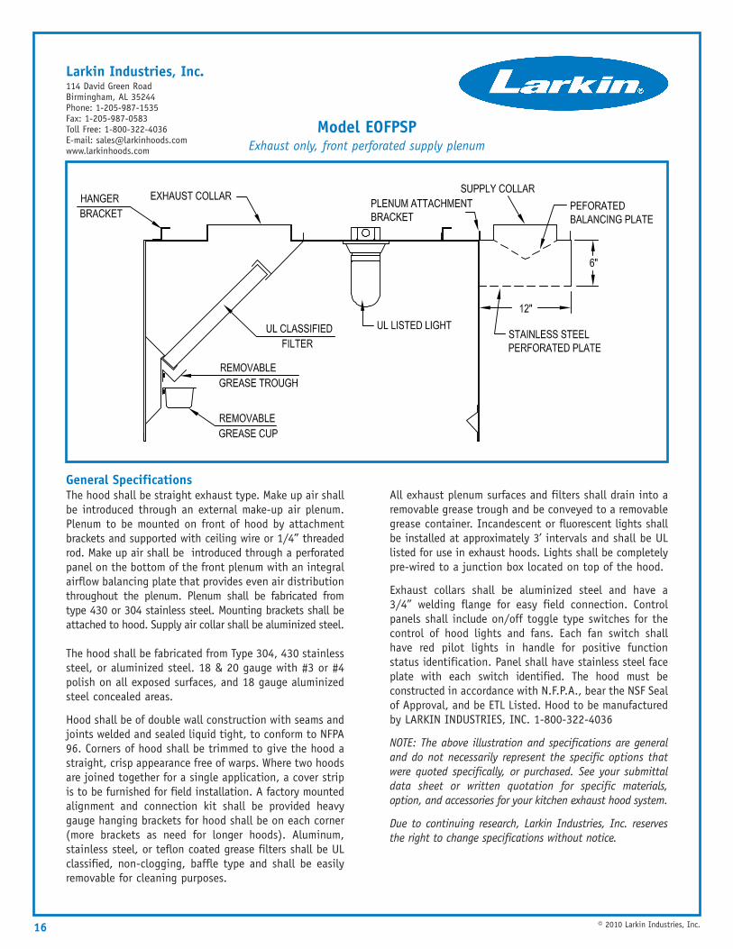
General SpecificationsThe hood shall be straight exhaust type. Make up air shallbe introduced through an external make-up air plenum.Plenum to be mounted on front of hood by attachmentbrackets and supported with ceiling wire or 1/4” threadedrod. Make up air shall be introduced through a perforatedpanel on the bottom of the front plenum with an integralairflow balancing plate that provides even air distributionthroughout the plenum. Plenum shall be fabricated fromtype 430 or 304 stainless steel. Mounting brackets shall beattached to hood. Supply air collar shall be aluminized steel.
The hood shall be fabricated from Type 304, 430 stainlesssteel, or aluminized steel. 18 & 20 gauge with #3 or #4polish on all exposed surfaces, and 18 gauge aluminizedsteel concealed areas.
Hood shall be of double wall construction with seams andjoints welded and sealed liquid tight, to conform to NFPA96. Corners of hood shall be trimmed to give the hood astraight, crisp appearance free of warps. Where two hoodsare joined together for a single application, a cover stripis to be furnished for field installation. A factory mountedalignment and connection kit shall be provided heavygauge hanging brackets for hood shall be on each corner(more brackets as need for longer hoods). Aluminum,stainless steel, or teflon coated grease filters shall be ULclassified, non-clogging, baffle type and shall be easilyremovable for cleaning purposes.
All exhaust plenum surfaces and filters shall drain into aremovable grease trough and be conveyed to a removablegrease container. Incandescent or fluorescent lights shallbe installed at approximately 3’ intervals and shall be ULlisted for use in exhaust hoods. Lights shall be completelypre-wired to a junction box located on top of the hood.
Exhaust collars shall be aluminized steel and have a3/4” welding flange for easy field connection. Controlpanels shall include on/off toggle type switches for thecontrol of hood lights and fans. Each fan switch shallhave red pilot lights in handle for positive functionstatus identification. Panel shall have stainless steel faceplate with each switch identified. The hood must beconstructed in accordance with N.F.P.A., bear the NSF Sealof Approval, and be ETL Listed. Hood to be manufacturedby LARKIN INDUSTRIES, INC. 1-800-322-4036
NOTE: The above illustration and specifications are generaland do not necessarily represent the specific options thatwere quoted specifically, or purchased. See your submittaldata sheet or written quotation for specific materials,option, and accessories for your kitchen exhaust hood system.
Due to continuing research, Larkin Industries, Inc. reservesthe right to change specifications without notice.
Model EOFPSPExhaust only, front perforated supply plenum
Larkin Industries, Inc.114 David Green RoadBirmingham, AL 35244Phone: 1-205-987-1535Fax: 1-205-987-0583Toll Free: 1-800-322-4036E-mail: [email protected]
17© 2010 Larkin Industries, Inc.
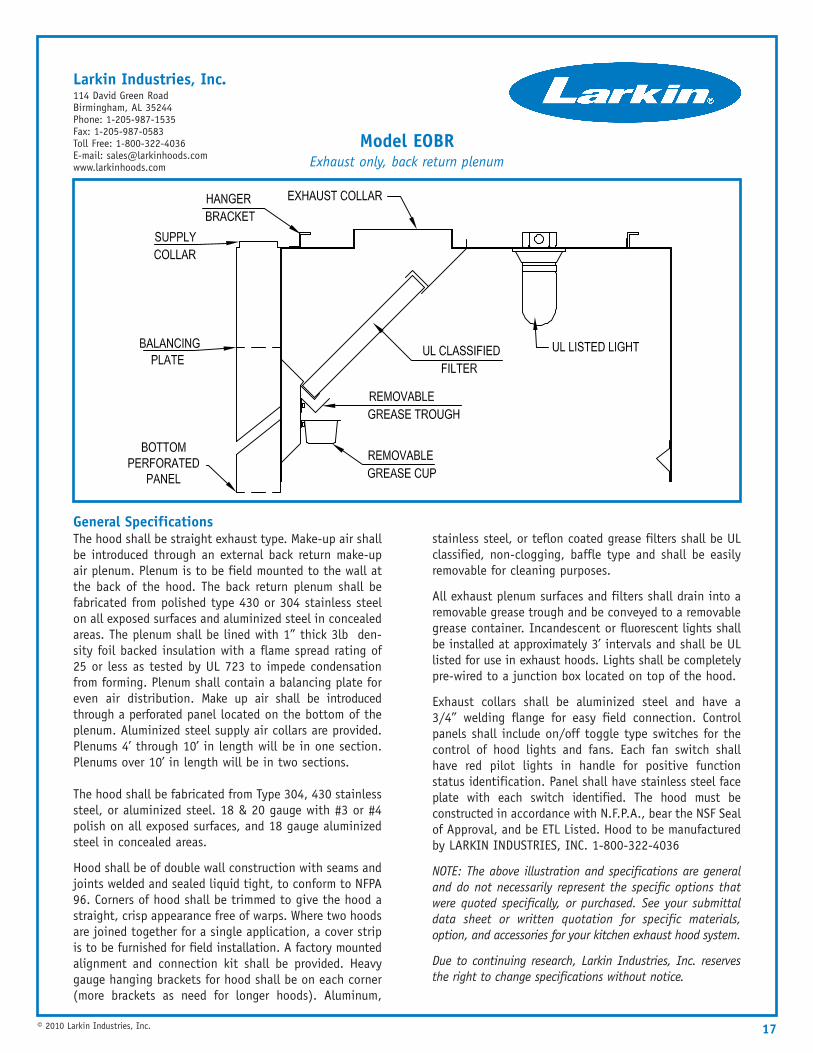
General SpecificationsThe hood shall be straight exhaust type. Make-up air shallbe introduced through an external back return make-upair plenum. Plenum is to be field mounted to the wall atthe back of the hood. The back return plenum shall befabricated from polished type 430 or 304 stainless steelon all exposed surfaces and aluminized steel in concealedareas. The plenum shall be lined with 1” thick 3lb den-sity foil backed insulation with a flame spread rating of25 or less as tested by UL 723 to impede condensationfrom forming. Plenum shall contain a balancing plate foreven air distribution. Make up air shall be introducedthrough a perforated panel located on the bottom of theplenum. Aluminized steel supply air collars are provided.Plenums 4’ through 10’ in length will be in one section.Plenums over 10’ in length will be in two sections.
The hood shall be fabricated from Type 304, 430 stainlesssteel, or aluminized steel. 18 & 20 gauge with #3 or #4polish on all exposed surfaces, and 18 gauge aluminizedsteel in concealed areas.
Hood shall be of double wall construction with seams andjoints welded and sealed liquid tight, to conform to NFPA96. Corners of hood shall be trimmed to give the hood astraight, crisp appearance free of warps. Where two hoodsare joined together for a single application, a cover stripis to be furnished for field installation. A factory mountedalignment and connection kit shall be provided. Heavygauge hanging brackets for hood shall be on each corner(more brackets as need for longer hoods). Aluminum,
stainless steel, or teflon coated grease filters shall be ULclassified, non-clogging, baffle type and shall be easilyremovable for cleaning purposes.
All exhaust plenum surfaces and filters shall drain into aremovable grease trough and be conveyed to a removablegrease container. Incandescent or fluorescent lights shallbe installed at approximately 3’ intervals and shall be ULlisted for use in exhaust hoods. Lights shall be completelypre-wired to a junction box located on top of the hood.
Exhaust collars shall be aluminized steel and have a3/4” welding flange for easy field connection. Controlpanels shall include on/off toggle type switches for thecontrol of hood lights and fans. Each fan switch shallhave red pilot lights in handle for positive functionstatus identification. Panel shall have stainless steel faceplate with each switch identified. The hood must beconstructed in accordance with N.F.P.A., bear the NSF Sealof Approval, and be ETL Listed. Hood to be manufacturedby LARKIN INDUSTRIES, INC. 1-800-322-4036
NOTE: The above illustration and specifications are generaland do not necessarily represent the specific options thatwere quoted specifically, or purchased. See your submittaldata sheet or written quotation for specific materials,option, and accessories for your kitchen exhaust hood system.
Due to continuing research, Larkin Industries, Inc. reservesthe right to change specifications without notice.
Model EOBRExhaust only, back return plenum
Larkin Industries, Inc.114 David Green RoadBirmingham, AL 35244Phone: 1-205-987-1535Fax: 1-205-987-0583Toll Free: 1-800-322-4036E-mail: [email protected]
Leading Self Compensating Hood Models
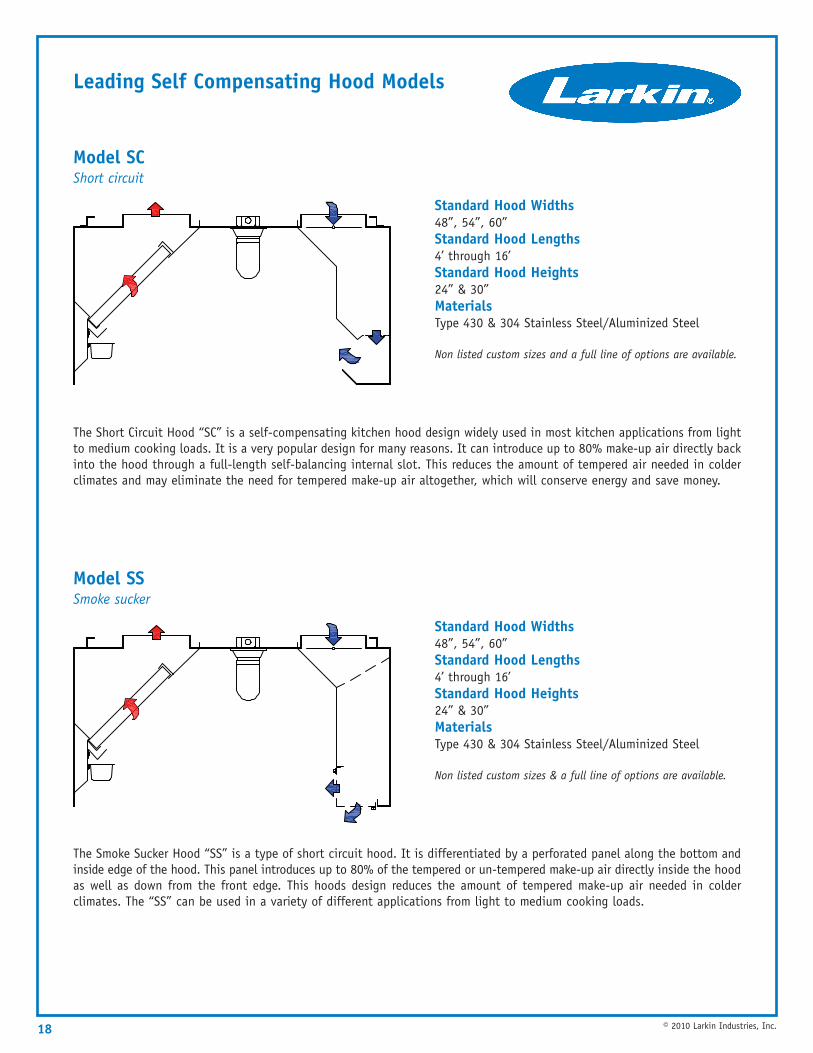
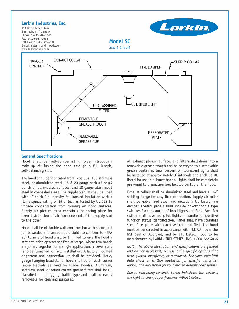
Model SC Short circuit
The Short Circuit Hood “SC” is a self-compensating kitchen hood design widely used in most kitchen applications from lightto medium cooking loads. It is a very popular design for many reasons. It can introduce up to 80% make-up air directly backinto the hood through a full-length self-balancing internal slot. This reduces the amount of tempered air needed in colderclimates and may eliminate the need for tempered make-up air altogether, which will conserve energy and save money.
Standard Hood Widths48”, 54”, 60”Standard Hood Lengths4’ through 16’Standard Hood Heights24” & 30”MaterialsType 430 & 304 Stainless Steel/Aluminized Steel
Non listed custom sizes and a full line of options are available.
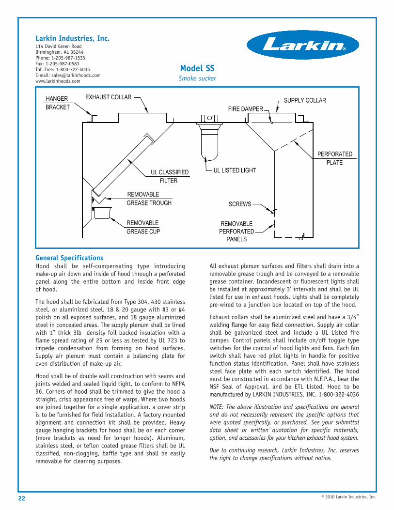
Model SS Smoke sucker
The Smoke Sucker Hood “SS” is a type of short circuit hood. It is differentiated by a perforated panel along the bottom andinside edge of the hood. This panel introduces up to 80% of the tempered or un-tempered make-up air directly inside the hoodas well as down from the front edge. This hoods design reduces the amount of tempered make-up air needed in colderclimates. The “SS” can be used in a variety of different applications from light to medium cooking loads.
Standard Hood Widths48”, 54”, 60”Standard Hood Lengths4’ through 16’Standard Hood Heights24” & 30”MaterialsType 430 & 304 Stainless Steel/Aluminized Steel
Non listed custom sizes & a full line of options are available.
18 © 2010 Larkin Industries, Inc.
Air Flow Data
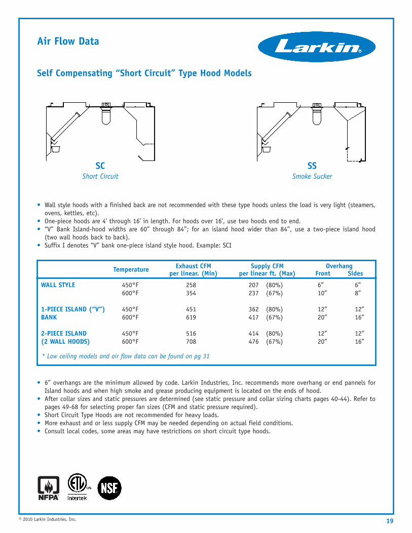
Self Compensating “Short Circuit” Type Hood Models
• Wall style hoods with a finished back are not recommended with these type hoods unless the load is very light (steamers,ovens, kettles, etc).
• One-piece hoods are 4’ through 16’ in length. For hoods over 16’, use two hoods end to end.• “V” Bank Island-hood widths are 60” through 84”; for an island hood wider than 84”, use a two-piece island hood
(two wall hoods back to back).• Suffix I denotes “V” bank one-piece island style hood. Example: SCI
• 6” overhangs are the minimum allowed by code. Larkin Industries, Inc. recommends more overhang or end pannels forIsland hoods and when high smoke and grease producing equipment is located on the ends of hood.
• After collar sizes and static pressures are determined (see static pressure and collar sizing charts pages 40-44). Refer topages 49-68 for selecting proper fan sizes (CFM and static pressure required).
• Short Circuit Type Hoods are not recommended for heavy loads.• More exhaust and or less supply CFM may be needed depending on actual field conditions.• Consult local codes, some areas may have restrictions on short circuit type hoods.
19© 2010 Larkin Industries, Inc.
Temperature Exhaust CFM per linear. (Min)
Supply CFM per linear ft. (Max)
Overhang Front Sides
WALL STYLE
1-PIECE ISLAND (“V”)BANK
2-PIECE ISLAND (2 WALL HOODS)
450°F 258 207 (80%) 6” 6”600°F 354 237 (67%) 10” 8”
450°F 451 362 (80%) 12” 12”600°F 619 417 (67%) 20” 16”
450°F 516 414 (80%) 12” 12”600°F 708 476 (67%) 20” 16”
* Low ceiling models and air flow data can be found on pg 31
SSSmoke Sucker
SCShort Circuit

20
Options Available On Short Circuit Hood Models
© 2010 Larkin Industries, Inc.
Options:
• 304 or 430 Stainless Steel
• Aluminized Steel
• All Stainless Steel Construction
• Finished Backs
• Standoffs 3”, 4”, 6”
• Insulated Standoffs
• Back Return Plenums
• ETL Listed Concentric Duct Plenums Available on 32” Tall Models
• Ceiling Skirts
• Wall Splash Panels and Trim
• End Panels
• 1,2,3, and 4 Switch Panels
• Auto Fan Control System
• ETL Listed Electrical Control Boxes 115v, 230v, 460v1 and 3-phase (hood mounted only)
• ANSUL Fire Suppression
• Fire Cabinets
• Volume Damper
• Listed Fire Damper in Exhaust Collar
• ETL Listed Low Ceiling Hoods
• Recessed Incandescent Lights
• Fluorescent Lights
• Stainless Steel Filters
• Epoxy-coated Filters
• Teflon-coated Filters
• High-Velocity Cartridge Filters
Full Descriptions and Drawings of all available options for all hood models are located after the design section of your Larkin catalog. Pg 70
21© 2010 Larkin Industries, Inc.
General SpecificationsHood shall be self-compensating type introducingmake-up air inside the hood through a full length,self-balancing slot.
The hood shall be fabricated from Type 304, 430 stainlesssteel, or aluminized steel. 18 & 20 gauge with #3 or #4polish on all exposed surfaces, and 18 gauge aluminizedsteel in concealed areas. The supply plenum shall be linedwith 1” thick 3lb density foil backed insulation with aflame spread rating of 25 or less as tested by UL 723 toimpede condensation from forming on hood surfaces.Supply air plenum must contain a balancing plate foreven distribution of air from one end of the supply slotto the other.
Hood shall be of double wall construction with seams andjoints welded and sealed liquid tight, to conform to NFPA96. Corners of hood shall be trimmed to give the hood astraight, crisp appearance free of warps. Where two hoodsare joined together for a single application, a cover stripis to be furnished for field installation. A factory mountedalignment and connection kit shall be provided. Heavygauge hanging brackets for hood shall be on each corner(more brackets as need for longer hoods). Aluminum,stainless steel, or teflon coated grease filters shall be ULclassified, non-clogging, baffle type and shall be easilyremovable for cleaning purposes.
All exhaust plenum surfaces and filters shall drain into aremovable grease trough and be conveyed to a removablegrease container. Incandescent or fluorescent lights shallbe installed at approximately 3’ intervals and shall be ULlisted for use in exhaust hoods. Lights shall be completelypre-wired to a junction box located on top of the hood.
Exhaust collars shall be aluminized steel and have a 3/4”welding flange for easy field connection. Supply air collarshall be galvanized steel and include a UL Listed firedamper. Control panels shall include on/off toggle typeswitches for the control of hood lights and fans. Each fanswitch shall have red pilot lights in handle for positivefunction status identification. Panel shall have stainlesssteel face plate with each switch identified. The hoodmust be constructed in accordance with N.F.P.A., bear theNSF Seal of Approval, and be ETL Listed. Hood to bemanufactured by LARKIN INDUSTRIES, INC. 1-800-322-4036
NOTE: The above illustration and specifications are generaland do not necessarily represent the specific options thatwere quoted specifically, or purchased. See your submittaldata sheet or written quotation for specific materials,option, and accessories for your kitchen exhaust hood system.
Due to continuing research, Larkin Industries, Inc. reservesthe right to change specifications without notice.
Model SCShort Circuit
Larkin Industries, Inc.114 David Green RoadBirmingham, AL 35244Phone: 1-205-987-1535Fax: 1-205-987-0583Toll Free: 1-800-322-4036E-mail: [email protected]
22 © 2010 Larkin Industries, Inc.
General SpecificationsHood shall be self-compensating type introducingmake-up air down and inside of hood through a perforatedpanel along the entire bottom and inside front edgeof hood.
The hood shall be fabricated from Type 304, 430 stainlesssteel, or aluminized steel. 18 & 20 gauge with #3 or #4polish on all exposed surfaces, and 18 gauge aluminizedsteel in concealed areas. The supply plenum shall be linedwith 1” thick 3lb density foil backed insulation with aflame spread rating of 25 or less as tested by UL 723 toimpede condensation from forming on hood surfaces.Supply air plenum must contain a balancing plate foreven distribution of make-up air.
Hood shall be of double wall construction with seams andjoints welded and sealed liquid tight, to conform to NFPA96. Corners of hood shall be trimmed to give the hood astraight, crisp appearance free of warps. Where two hoodsare joined together for a single application, a cover stripis to be furnished for field installation. A factory mountedalignment and connection kit shall be provided. Heavygauge hanging brackets for hood shall be on each corner(more brackets as need for longer hoods). Aluminum,stainless steel, or teflon coated grease filters shall be ULclassified, non-clogging, baffle type and shall be easilyremovable for cleaning purposes.
All exhaust plenum surfaces and filters shall drain into aremovable grease trough and be conveyed to a removablegrease container. Incandescent or fluorescent lights shallbe installed at approximately 3’ intervals and shall be ULlisted for use in exhaust hoods. Lights shall be completelypre-wired to a junction box located on top of the hood.
Exhaust collars shall be aluminized steel and have a 3/4”welding flange for easy field connection. Supply air collarshall be galvanized steel and include a UL Listed firedamper. Control panels shall include on/off toggle typeswitches for the control of hood lights and fans. Each fanswitch shall have red pilot lights in handle for positivefunction status identification. Panel shall have stainlesssteel face plate with each switch identified. The hoodmust be constructed in accordance with N.F.P.A., bear theNSF Seal of Approval, and be ETL Listed. Hood to bemanufactured by LARKIN INDUSTRIES, INC. 1-800-322-4036
NOTE: The above illustration and specifications are generaland do not necessarily represent the specific options thatwere quoted specifically, or purchased. See your submittaldata sheet or written quotation for specific materials,option, and accessories for your kitchen exhaust hood system.
Due to continuing research, Larkin Industries, Inc. reservesthe right to change specifications without notice.
Model SSSmoke sucker
Larkin Industries, Inc.114 David Green RoadBirmingham, AL 35244Phone: 1-205-987-1535Fax: 1-205-987-0583Toll Free: 1-800-322-4036E-mail: [email protected]
Leading Compensating Hood Models
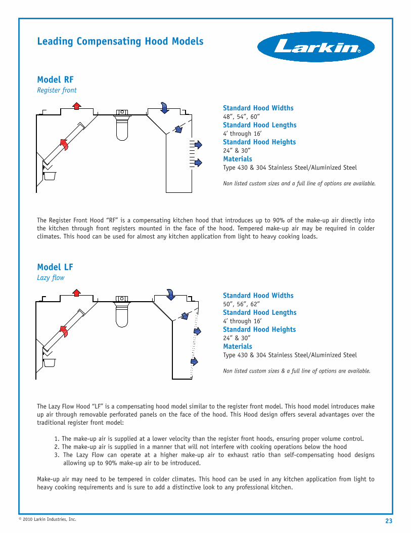
The Register Front Hood “RF” is a compensating kitchen hood that introduces up to 90% of the make-up air directly intothe kitchen through front registers mounted in the face of the hood. Tempered make-up air may be required in colderclimates. This hood can be used for almost any kitchen application from light to heavy cooking loads.
Standard Hood Widths48”, 54”, 60”Standard Hood Lengths4’ through 16’Standard Hood Heights24” & 30”MaterialsType 430 & 304 Stainless Steel/Aluminized Steel
Non listed custom sizes and a full line of options are available.
The Lazy Flow Hood “LF” is a compensating hood model similar to the register front model. This hood model introduces makeup air through removable perforated panels on the face of the hood. This Hood design offers several advantages over thetraditional register front model:
1. The make-up air is supplied at a lower velocity than the register front hoods, ensuring proper volume control. 2. The make-up air is supplied in a manner that will not interfere with cooking operations below the hood 3. The Lazy Flow can operate at a higher make-up air to exhaust ratio than self-compensating hood designs
allowing up to 90% make-up air to be introduced.
Make-up air may need to be tempered in colder climates. This hood can be used in any kitchen application from light toheavy cooking requirements and is sure to add a distinctive look to any professional kitchen.
Standard Hood Widths50”, 56”, 62”Standard Hood Lengths4’ through 16’Standard Hood Heights24” & 30”MaterialsType 430 & 304 Stainless Steel/Aluminized Steel
Non listed custom sizes & a full line of options are available.
23© 2010 Larkin Industries, Inc.
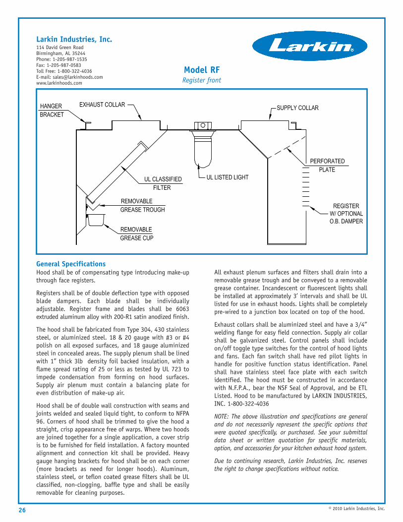
Model RF Register front
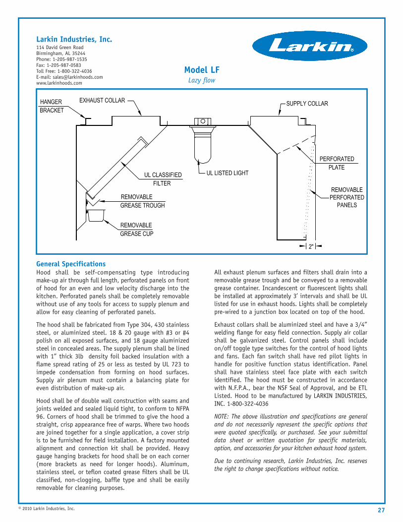
Model LF Lazy flow
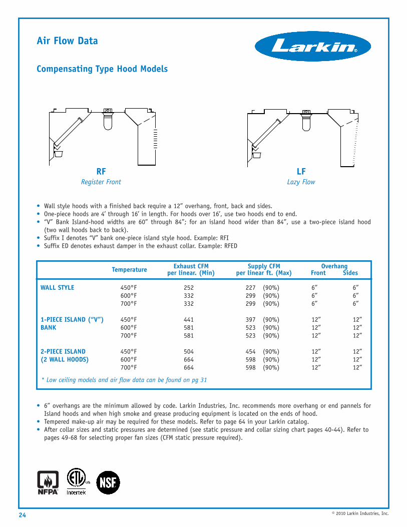
Air Flow Data
Compensating Type Hood Models
• Wall style hoods with a finished back require a 12” overhang, front, back and sides.• One-piece hoods are 4’ through 16’ in length. For hoods over 16’, use two hoods end to end.• “V” Bank Island-hood widths are 60” through 84”; for an island hood wider than 84”, use a two-piece island hood
(two wall hoods back to back).• Suffix I denotes “V” bank one-piece island style hood. Example: RFI• Suffix ED denotes exhaust damper in the exhaust collar. Example: RFED
• 6” overhangs are the minimum allowed by code. Larkin Industries, Inc. recommends more overhang or end pannels forIsland hoods and when high smoke and grease producing equipment is located on the ends of hood.
• Tempered make-up air may be required for these models. Refer to page 64 in your Larkin catalog.• After collar sizes and static pressures are determined (see static pressure and collar sizing chart pages 40-44). Refer to
pages 49-68 for selecting proper fan sizes (CFM static pressure required).
24 © 2010 Larkin Industries, Inc.
Temperature Exhaust CFM per linear. (Min)
Supply CFM per linear ft. (Max)
Overhang Front Sides
WALL STYLE
1-PIECE ISLAND (“V”)BANK
2-PIECE ISLAND (2 WALL HOODS)
450°F 252 227 (90%) 6” 6”600°F 332 299 (90%) 6” 6”700°F 332 299 (90%) 6” 6”
450°F 441 397 (90%) 12” 12”600°F 581 523 (90%) 12” 12”700°F 581 523 (90%) 12” 12”
450°F 504 454 (90%) 12” 12”600°F 664 598 (90%) 12” 12”700°F 664 598 (90%) 12” 12”
* Low ceiling models and air flow data can be found on pg 31
LFLazy Flow
RFRegister Front
25
Options Available On Front Discharge Hood Models
© 2010 Larkin Industries, Inc.
Options:
• 304 or 430 Stainless Steel
• Aluminized Steel
• All Stainless Steel Construction
• Finished Backs
• Standoffs 3”, 4”, 6”
• Insulated Standoffs
• Full Insulated Plenums
• ETL Listed Concentric Duct Plenums Available on 32” Tall Models
• Ceiling Skirts
• Wall Splash Panels and Trim
• End Panels
• 1,2,3, and 4 Switch Panels
• Auto Fan Control System
• ETL Listed Electrical Control Boxes 115v, 230v, 460v1 and 3-phase (hood mounted only)
• ANSUL Fire Suppression
• Fire Cabinets
• Listed Fire Damper in Exhaust Collar
• Volume Damper
• ETL Listed Low Ceiling Hoods
• Recessed Incandescent Lights
• Fluorescent Lights
• Stainless Steel Filters
• Epoxy-coated Filters
• Teflon-coated Filters
• High-Velocity Cartridge Filters
Full Descriptions and Drawings of all available options for all hood models are located after the design section of your Larkin catalog. Pg 70
26 © 2010 Larkin Industries, Inc.
General SpecificationsHood shall be of compensating type introducing make-upthrough face registers.
Registers shall be of double deflection type with opposedblade dampers. Each blade shall be individuallyadjustable. Register frame and blades shall be 6063extruded aluminum alloy with 200-R1 satin anodized finish.
The hood shall be fabricated from Type 304, 430 stainlesssteel, or aluminized steel. 18 & 20 gauge with #3 or #4polish on all exposed surfaces, and 18 gauge aluminizedsteel in concealed areas. The supply plenum shall be linedwith 1” thick 3lb density foil backed insulation, with aflame spread rating of 25 or less as tested by UL 723 toimpede condensation from forming on hood surfaces.Supply air plenum must contain a balancing plate foreven distribution of make-up air.
Hood shall be of double wall construction with seams andjoints welded and sealed liquid tight, to conform to NFPA96. Corners of hood shall be trimmed to give the hood astraight, crisp appearance free of warps. Where two hoodsare joined together for a single application, a cover stripis to be furnished for field installation. A factory mountedalignment and connection kit shall be provided. Heavygauge hanging brackets for hood shall be on each corner(more brackets as need for longer hoods). Aluminum,stainless steel, or teflon coated grease filters shall be ULclassified, non-clogging, baffle type and shall be easilyremovable for cleaning purposes.
All exhaust plenum surfaces and filters shall drain into aremovable grease trough and be conveyed to a removablegrease container. Incandescent or fluorescent lights shallbe installed at approximately 3’ intervals and shall be ULlisted for use in exhaust hoods. Lights shall be completelypre-wired to a junction box located on top of the hood.
Exhaust collars shall be aluminized steel and have a 3/4”welding flange for easy field connection. Supply air collarshall be galvanized steel. Control panels shall includeon/off toggle type switches for the control of hood lightsand fans. Each fan switch shall have red pilot lights inhandle for positive function status identification. Panelshall have stainless steel face plate with each switchidentified. The hood must be constructed in accordancewith N.F.P.A., bear the NSF Seal of Approval, and be ETLListed. Hood to be manufactured by LARKIN INDUSTRIES,INC. 1-800-322-4036
NOTE: The above illustration and specifications are generaland do not necessarily represent the specific options thatwere quoted specifically, or purchased. See your submittaldata sheet or written quotation for specific materials,option, and accessories for your kitchen exhaust hood system.
Due to continuing research, Larkin Industries, Inc. reservesthe right to change specifications without notice.
Model RFRegister front
Larkin Industries, Inc.114 David Green RoadBirmingham, AL 35244Phone: 1-205-987-1535Fax: 1-205-987-0583Toll Free: 1-800-322-4036E-mail: [email protected]
27© 2010 Larkin Industries, Inc.
General SpecificationsHood shall be self-compensating type introducingmake-up air through full length, perforated panels on frontof hood for an even and low velocity discharge into thekitchen. Perforated panels shall be completely removablewithout use of any tools for access to supply plenum andallow for easy cleaning of perforated panels.
The hood shall be fabricated from Type 304, 430 stainlesssteel, or aluminized steel. 18 & 20 gauge with #3 or #4polish on all exposed surfaces, and 18 gauge aluminizedsteel in concealed areas. The supply plenum shall be linedwith 1” thick 3lb density foil backed insulation with aflame spread rating of 25 or less as tested by UL 723 toimpede condensation from forming on hood surfaces.Supply air plenum must contain a balancing plate foreven distribution of make-up air.
Hood shall be of double wall construction with seams andjoints welded and sealed liquid tight, to conform to NFPA96. Corners of hood shall be trimmed to give the hood astraight, crisp appearance free of warps. Where two hoodsare joined together for a single application, a cover stripis to be furnished for field installation. A factory mountedalignment and connection kit shall be provided. Heavygauge hanging brackets for hood shall be on each corner(more brackets as need for longer hoods). Aluminum,stainless steel, or teflon coated grease filters shall be ULclassified, non-clogging, baffle type and shall be easilyremovable for cleaning purposes.
All exhaust plenum surfaces and filters shall drain into aremovable grease trough and be conveyed to a removablegrease container. Incandescent or fluorescent lights shallbe installed at approximately 3’ intervals and shall be ULlisted for use in exhaust hoods. Lights shall be completelypre-wired to a junction box located on top of the hood.
Exhaust collars shall be aluminized steel and have a 3/4”welding flange for easy field connection. Supply air collarshall be galvanized steel. Control panels shall includeon/off toggle type switches for the control of hood lightsand fans. Each fan switch shall have red pilot lights inhandle for positive function status identification. Panelshall have stainless steel face plate with each switchidentified. The hood must be constructed in accordancewith N.F.P.A., bear the NSF Seal of Approval, and be ETLListed. Hood to be manufactured by LARKIN INDUSTRIES,INC. 1-800-322-4036
NOTE: The above illustration and specifications are generaland do not necessarily represent the specific options thatwere quoted specifically, or purchased. See your submittaldata sheet or written quotation for specific materials,option, and accessories for your kitchen exhaust hood system.
Due to continuing research, Larkin Industries, Inc. reservesthe right to change specifications without notice.
Model LFLazy flow
Larkin Industries, Inc.114 David Green RoadBirmingham, AL 35244Phone: 1-205-987-1535Fax: 1-205-987-0583Toll Free: 1-800-322-4036E-mail: [email protected]
Air Flow Data
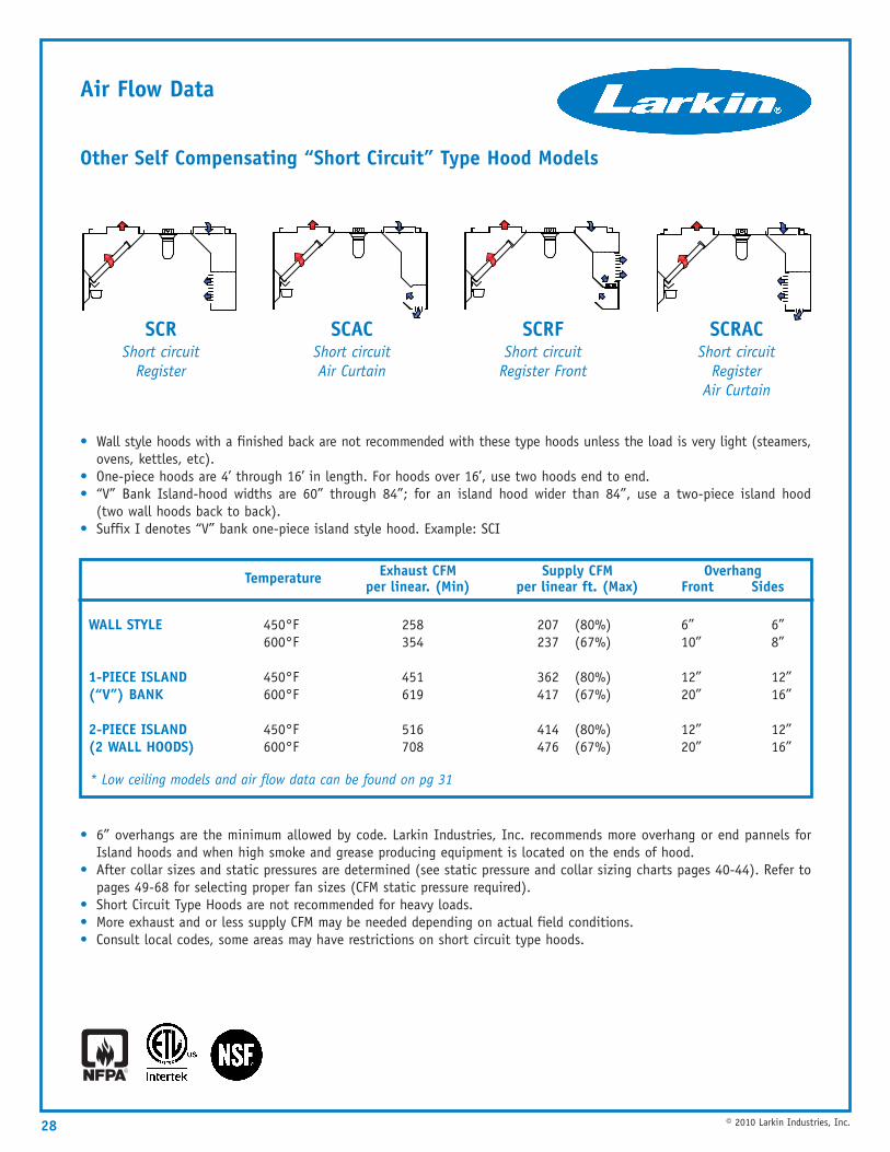
Other Self Compensating “Short Circuit” Type Hood Models
• Wall style hoods with a finished back are not recommended with these type hoods unless the load is very light (steamers,ovens, kettles, etc).
• One-piece hoods are 4’ through 16’ in length. For hoods over 16’, use two hoods end to end.• “V” Bank Island-hood widths are 60” through 84”; for an island hood wider than 84”, use a two-piece island hood
(two wall hoods back to back).• Suffix I denotes “V” bank one-piece island style hood. Example: SCI
• 6” overhangs are the minimum allowed by code. Larkin Industries, Inc. recommends more overhang or end pannels forIsland hoods and when high smoke and grease producing equipment is located on the ends of hood.
• After collar sizes and static pressures are determined (see static pressure and collar sizing charts pages 40-44). Refer topages 49-68 for selecting proper fan sizes (CFM static pressure required).
• Short Circuit Type Hoods are not recommended for heavy loads.• More exhaust and or less supply CFM may be needed depending on actual field conditions.• Consult local codes, some areas may have restrictions on short circuit type hoods.
28 © 2010 Larkin Industries, Inc.
Temperature Exhaust CFM per linear. (Min)
Supply CFM per linear ft. (Max)
Overhang Front Sides
WALL STYLE
1-PIECE ISLAND (“V”) BANK
2-PIECE ISLAND (2 WALL HOODS)
450°F 258 207 (80%) 6” 6”600°F 354 237 (67%) 10” 8”
450°F 451 362 (80%) 12” 12”600°F 619 417 (67%) 20” 16”
450°F 516 414 (80%) 12” 12”600°F 708 476 (67%) 20” 16”
SCR Short circuit
Register
SCAC Short circuitAir Curtain
SCRF Short circuit
Register Front
SCRAC Short circuit
RegisterAir Curtain
* Low ceiling models and air flow data can be found on pg 31
Air Flow Data
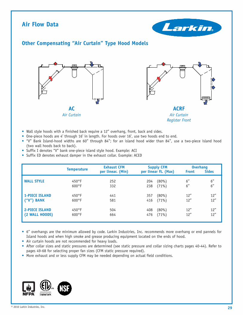
Other Compensating “Air Curtain” Type Hood Models
• Wall style hoods with a finished back require a 12” overhang, front, back and sides.• One-piece hoods are 4’ through 16’ in length. For hoods over 16’, use two hoods end to end.• “V” Bank Island-hood widths are 60” through 84”; for an island hood wider than 84”, use a two-piece island hood
(two wall hoods back to back).• Suffix I denotes “V” bank one-piece island style hood. Example: ACI• Suffix ED denotes exhaust damper in the exhaust collar. Example: ACED
• 6” overhangs are the minimum allowed by code. Larkin Industries, Inc. recommends more overhang or end pannels forIsland hoods and when high smoke and grease producing equipment located on the ends of hood.
• Air curtain hoods are not recommended for heavy loads.• After collar sizes and static pressures are determined (see static pressure and collar sizing charts pages 40-44). Refer to
pages 49-68 for selecting proper fan sizes (CFM static pressure required).• More exhaust and or less supply CFM may be needed depending on actual field conditions.
29© 2010 Larkin Industries, Inc.
Temperature Exhaust CFM per linear. (Min)
Supply CFM per linear ft. (Max)
Overhang Front Sides
WALL STYLE
1-PIECE ISLAND (“V”) BANK
2-PIECE ISLAND (2 WALL HOODS)
450°F 252 204 (80%) 6” 6”600°F 332 238 (71%) 6” 6”
450°F 441 357 (80%) 12” 12”600°F 581 416 (71%) 12” 12”
450°F 504 408 (80%) 12” 12”600°F 664 476 (71%) 12” 12”
ACAir Curtain
ACRF Air Curtain
Register Front
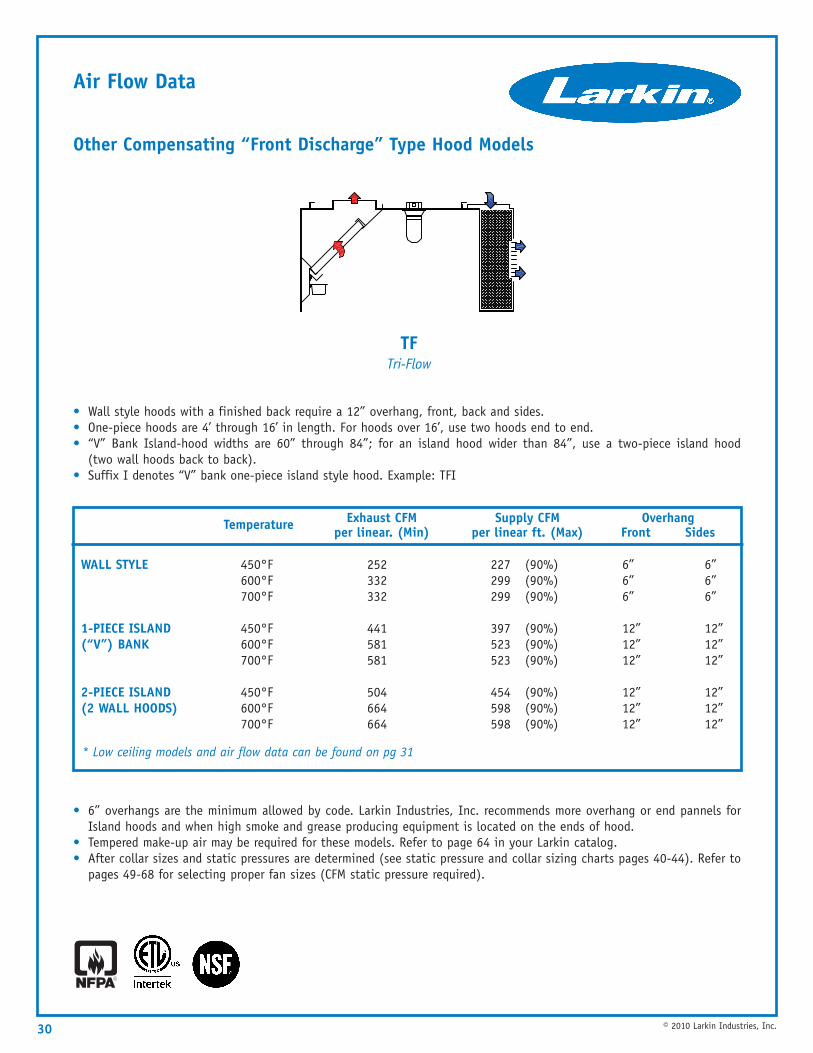
Air Flow Data
Other Compensating “Front Discharge” Type Hood Models
• Wall style hoods with a finished back require a 12” overhang, front, back and sides.• One-piece hoods are 4’ through 16’ in length. For hoods over 16’, use two hoods end to end.• “V” Bank Island-hood widths are 60” through 84”; for an island hood wider than 84”, use a two-piece island hood
(two wall hoods back to back).• Suffix I denotes “V” bank one-piece island style hood. Example: TFI
• 6” overhangs are the minimum allowed by code. Larkin Industries, Inc. recommends more overhang or end pannels forIsland hoods and when high smoke and grease producing equipment is located on the ends of hood.
• Tempered make-up air may be required for these models. Refer to page 64 in your Larkin catalog.• After collar sizes and static pressures are determined (see static pressure and collar sizing charts pages 40-44). Refer to
pages 49-68 for selecting proper fan sizes (CFM static pressure required).
30 © 2010 Larkin Industries, Inc.
Temperature Exhaust CFM per linear. (Min)
Supply CFM per linear ft. (Max)
Overhang Front Sides
WALL STYLE
1-PIECE ISLAND (“V”) BANK
2-PIECE ISLAND (2 WALL HOODS)
450°F 252 227 (90%) 6” 6”600°F 332 299 (90%) 6” 6”700°F 332 299 (90%) 6” 6”
450°F 441 397 (90%) 12” 12”600°F 581 523 (90%) 12” 12”700°F 581 523 (90%) 12” 12”
450°F 504 454 (90%) 12” 12”600°F 664 598 (90%) 12” 12”700°F 664 598 (90%) 12” 12”
* Low ceiling models and air flow data can be found on pg 31
TFTri-Flow
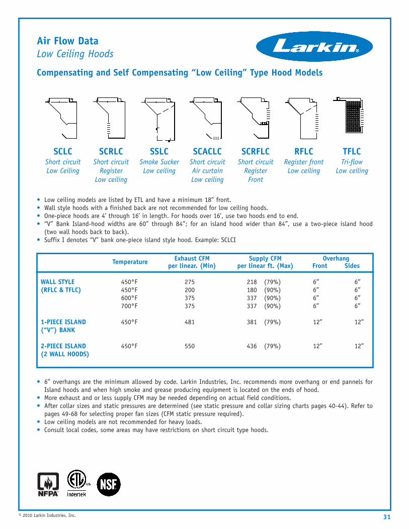
Air Flow DataLow Ceiling Hoods
Compensating and Self Compensating “Low Ceiling” Type Hood Models
• Low ceiling models are listed by ETL and have a minimum 18” front.• Wall style hoods with a finished back are not recommended for low ceiling hoods.• One-piece hoods are 4’ through 16’ in length. For hoods over 16’, use two hoods end to end.• “V” Bank Island-hood widths are 60” through 84”; for an island hood wider than 84”, use a two-piece island hood
(two wall hoods back to back).• Suffix I denotes “V” bank one-piece island style hood. Example: SCLCI
• 6” overhangs are the minimum allowed by code. Larkin Industries, Inc. recommends more overhang or end pannels forIsland hoods and when high smoke and grease producing equipment is located on the ends of hood.
• More exhaust and or less supply CFM may be needed depending on actual field conditions.• After collar sizes and static pressures are determined (see static pressure and collar sizing charts pages 40-44). Refer to
pages 49-68 for selecting proper fan sizes (CFM static pressure required).• Low ceiling models are not recommended for heavy loads.• Consult local codes, some areas may have restrictions on short circuit type hoods.
31© 2010 Larkin Industries, Inc.
Temperature Exhaust CFM per linear. (Min)
Supply CFM per linear ft. (Max)
Overhang Front Sides
WALL STYLE(RFLC & TFLC)
1-PIECE ISLAND (“V”) BANK
2-PIECE ISLAND (2 WALL HOODS)
450°F 275 218 (79%) 6” 6”450°F 200 180 (90%) 6” 6”600°F 375 337 (90%) 6” 6”700°F 375 337 (90%) 6” 6”
450°F 481 381 (79%) 12” 12”
450°F 550 436 (79%) 12” 12”
SCLC Short circuitLow Ceiling
SCRLC Short circuit
RegisterLow ceiling
SSLC Smoke SuckerLow ceiling
SCACLC Short circuitAir curtainLow ceiling
SCRFLC Short circuit
RegisterFront
RFLC Register frontLow ceiling
TFLC Tri-flow
Low ceiling
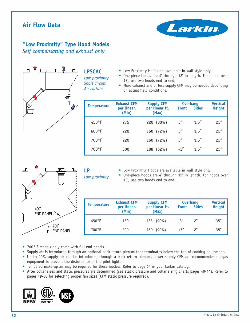
Air Flow Data
“Low Proximity” Type Hood ModelsSelf compensating and exhaust only
• 700° F models only come with full end panels• Supply air is introduced through an optional back return plenum that terminates below the top of cooking equipment.• Up to 90% supply air can be introduced, through a back return plenum. Lower supply CFM are recommended on gas
equipment to prevent the disturbance of the pilot light.• Tempered make-up air may be required for these models. Refer to page 64 in your Larkin catalog.• After collar sizes and static pressures are determined (see static pressure and collar sizing charts pages 40-44). Refer to
pages 49-68 for selecting proper fan sizes (CFM static pressure required).
• Low Proximity Hoods are available in wall style only.• One-piece hoods are 4’ through 12’ in length. For hoods over
12’, use two hoods end to end.• More exhaust and or less supply CFM may be needed depending
on actual field conditions.
• Low Proximity Hoods are available in wall style only.• One-piece hoods are 4’ through 12’ in length. For hoods over
12’, use two hoods end to end.
32 © 2010 Larkin Industries, Inc.
Temperature Exhaust CFM per linear.
(Min)
Supply CFM per linear ft.
(Max)
Overhang Front Sides
VerticalHeight
450°F 275 220 (80%) 5” 1.5” 25”
600°F 220 160 (72%) 5” 1.5” 25”
700°F 220 160 (72%) 5” 1.5” 25”
700°F 300 188 (62%) -1” 1.5” 25”
Temperature Exhaust CFM per linear.
(Min)
Supply CFM per linear ft.
(Max)
Overhang Front Sides
VerticalHeight
450°F 150 135 (90%) -3” 2” 35”
700°F 200 180 (90%) +3” 2” 35”
LPSCACLow proximityShort circuitAir curtain
LPLow proximity
33© 2010 Larkin Industries, Inc.
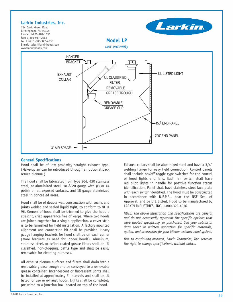
General SpecificationsHood shall be of low proximity straight exhaust type.(Make-up air can be introduced through an optional backreturn plenum.)
The hood shall be fabricated from Type 304, 430 stainlesssteel, or aluminized steel. 18 & 20 gauge with #3 or #4polish on all exposed surfaces, and 18 gauge aluminizedsteel in concealed areas.
Hood shall be of double wall construction with seams andjoints welded and sealed liquid tight, to conform to NFPA96. Corners of hood shall be trimmed to give the hood astraight, crisp appearance free of warps. Where two hoodsare joined together for a single application, a cover stripis to be furnished for field installation. A factory mountedalignment and connection kit shall be provided. Heavygauge hanging brackets for hood shall be on each corner(more brackets as need for longer hoods). Aluminum,stainless steel, or teflon coated grease filters shall be ULclassified, non-clogging, baffle type and shall be easilyremovable for cleaning purposes.
All exhaust plenum surfaces and filters shall drain into aremovable grease trough and be conveyed to a removablegrease container. Incandescent or fluorescent lights shallbe installed at approximately 3’ intervals and shall be ULlisted for use in exhaust hoods. Lights shall be completelypre-wired to a junction box located on top of the hood.
Exhaust collars shall be aluminized steel and have a 3/4”welding flange for easy field connection. Control panelsshall include on/off toggle type switches for the controlof hood lights and fans. Each fan switch shall havered pilot lights in handle for positive function statusidentification. Panel shall have stainless steel face platewith each switch identified. The hood must be constructedin accordance with N.F.P.A., bear the NSF Seal ofApproval, and be ETL Listed. Hood to be manufactured byLARKIN INDUSTRIES, INC. 1-800-322-4036
NOTE: The above illustration and specifications are generaland do not necessarily represent the specific options thatwere quoted specifically, or purchased. See your submittaldata sheet or written quotation for specific materials,option, and accessories for your kitchen exhaust hood system.
Due to continuing research, Larkin Industries, Inc. reservesthe right to change specifications without notice.
Model LPLow proximity
Larkin Industries, Inc.114 David Green RoadBirmingham, AL 35244Phone: 1-205-987-1535Fax: 1-205-987-0583Toll Free: 1-800-322-4036E-mail: [email protected]
Air Flow Data
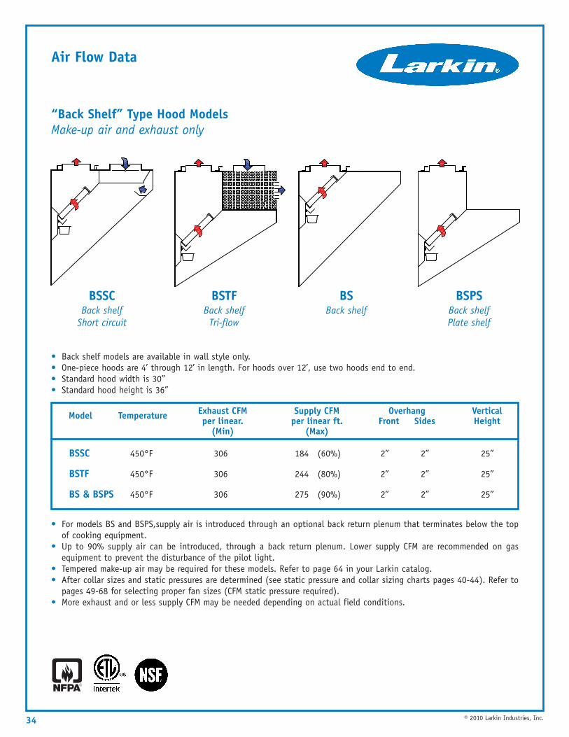
“Back Shelf” Type Hood ModelsMake-up air and exhaust only
• Back shelf models are available in wall style only.• One-piece hoods are 4’ through 12’ in length. For hoods over 12’, use two hoods end to end.• Standard hood width is 30”• Standard hood height is 36”
• For models BS and BSPS,supply air is introduced through an optional back return plenum that terminates below the topof cooking equipment.
• Up to 90% supply air can be introduced, through a back return plenum. Lower supply CFM are recommended on gasequipment to prevent the disturbance of the pilot light.
• Tempered make-up air may be required for these models. Refer to page 64 in your Larkin catalog.• After collar sizes and static pressures are determined (see static pressure and collar sizing charts pages 40-44). Refer to
pages 49-68 for selecting proper fan sizes (CFM static pressure required).• More exhaust and or less supply CFM may be needed depending on actual field conditions.
34 © 2010 Larkin Industries, Inc.
TemperatureModel Exhaust CFM per linear.
(Min)
Supply CFM per linear ft.
(Max)
Overhang Front Sides
VerticalHeight
BSSC 450°F 306 184 (60%) 2” 2” 25”
BSTF 450°F 306 244 (80%) 2” 2” 25”
BS & BSPS 450°F 306 275 (90%) 2” 2” 25”
BSSCBack shelf
Short circuit
BSTFBack shelfTri-flow
BSBack shelf
BSPSBack shelfPlate shelf
35© 2010 Larkin Industries, Inc.
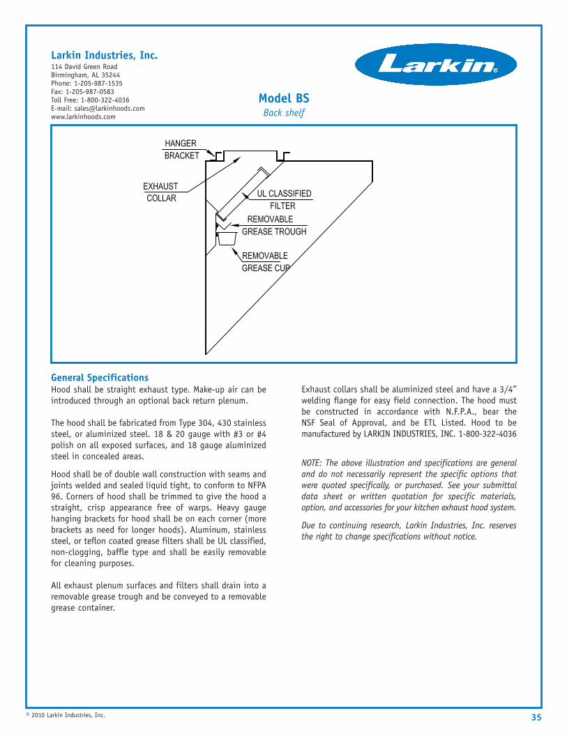
General SpecificationsHood shall be straight exhaust type. Make-up air can beintroduced through an optional back return plenum.
The hood shall be fabricated from Type 304, 430 stainlesssteel, or aluminized steel. 18 & 20 gauge with #3 or #4polish on all exposed surfaces, and 18 gauge aluminizedsteel in concealed areas.
Hood shall be of double wall construction with seams andjoints welded and sealed liquid tight, to conform to NFPA96. Corners of hood shall be trimmed to give the hood astraight, crisp appearance free of warps. Heavy gaugehanging brackets for hood shall be on each corner (morebrackets as need for longer hoods). Aluminum, stainlesssteel, or teflon coated grease filters shall be UL classified,non-clogging, baffle type and shall be easily removablefor cleaning purposes.
All exhaust plenum surfaces and filters shall drain into aremovable grease trough and be conveyed to a removablegrease container.
Exhaust collars shall be aluminized steel and have a 3/4”welding flange for easy field connection. The hood mustbe constructed in accordance with N.F.P.A., bear theNSF Seal of Approval, and be ETL Listed. Hood to bemanufactured by LARKIN INDUSTRIES, INC. 1-800-322-4036
NOTE: The above illustration and specifications are generaland do not necessarily represent the specific options thatwere quoted specifically, or purchased. See your submittaldata sheet or written quotation for specific materials,option, and accessories for your kitchen exhaust hood system.
Due to continuing research, Larkin Industries, Inc. reservesthe right to change specifications without notice.
Model BSBack shelf
Larkin Industries, Inc.114 David Green RoadBirmingham, AL 35244Phone: 1-205-987-1535Fax: 1-205-987-0583Toll Free: 1-800-322-4036E-mail: [email protected]
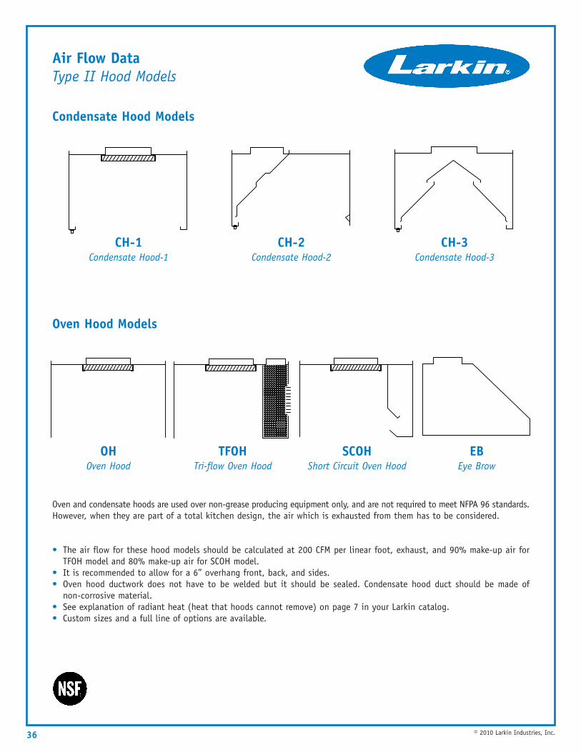
Air Flow DataType II Hood Models
Condensate Hood Models
Oven Hood Models
Oven and condensate hoods are used over non-grease producing equipment only, and are not required to meet NFPA 96 standards.However, when they are part of a total kitchen design, the air which is exhausted from them has to be considered.
• The air flow for these hood models should be calculated at 200 CFM per linear foot, exhaust, and 90% make-up air forTFOH model and 80% make-up air for SCOH model.
• It is recommended to allow for a 6” overhang front, back, and sides.• Oven hood ductwork does not have to be welded but it should be sealed. Condensate hood duct should be made of
non-corrosive material.• See explanation of radiant heat (heat that hoods cannot remove) on page 7 in your Larkin catalog.• Custom sizes and a full line of options are available.
36 © 2010 Larkin Industries, Inc.
CH-1Condensate Hood-1
CH-2Condensate Hood-2
CH-3Condensate Hood-3
OHOven Hood
TFOHTri-flow Oven Hood
SCOHShort Circuit Oven Hood
EBEye Brow
37
*For air flow information consult factory.Due to wide variations in state, county and city codes, Larkin Industries, Inc must be advised of any special requirements in construction ordesign at time of quotation.
© 2010 Larkin Industries, Inc.
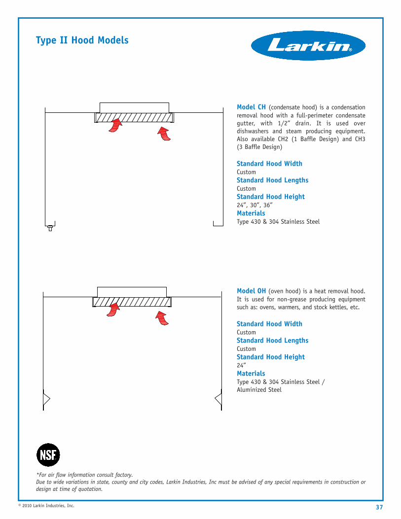
Type II Hood Models
Model CH (condensate hood) is a condensationremoval hood with a full-perimeter condensategutter, with 1/2” drain. It is used overdishwashers and steam producing equipment.Also available CH2 (1 Baffle Design) and CH3(3 Baffle Design)
Standard Hood Width CustomStandard Hood Lengths CustomStandard Hood Height 24”, 30”, 36”MaterialsType 430 & 304 Stainless Steel
Model OH (oven hood) is a heat removal hood.It is used for non-grease producing equipmentsuch as: ovens, warmers, and stock kettles, etc.
Standard Hood Width CustomStandard Hood Lengths CustomStandard Hood Height 24”MaterialsType 430 & 304 Stainless Steel / Aluminized Steel
38
*For air flow information consult factory.Due to wide variations in state, county and city codes, Larkin Industries, Inc must be advised of any special requirements in construction ordesign at time of quotation.
© 2010 Larkin Industries, Inc.
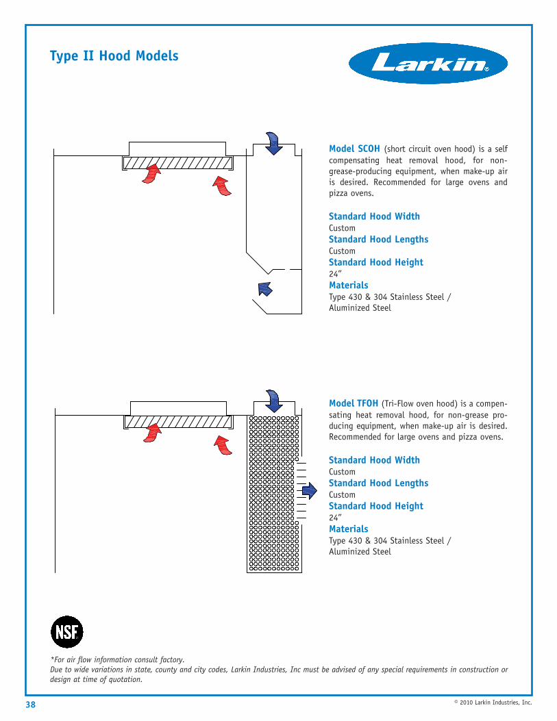
Type II Hood Models
Model SCOH (short circuit oven hood) is a selfcompensating heat removal hood, for non-grease-producing equipment, when make-up airis desired. Recommended for large ovens andpizza ovens.
Standard Hood Width CustomStandard Hood Lengths CustomStandard Hood Height 24”MaterialsType 430 & 304 Stainless Steel / Aluminized Steel
Model TFOH (Tri-Flow oven hood) is a compen-sating heat removal hood, for non-grease pro-ducing equipment, when make-up air is desired.Recommended for large ovens and pizza ovens.
Standard Hood Width CustomStandard Hood Lengths CustomStandard Hood Height 24”MaterialsType 430 & 304 Stainless Steel / Aluminized Steel
39
Fan Selection Guide
In order to select the proper size fans, the following must be known:
**NOTE: This example does not include any static pressure loss for duct system**
© 2010 Larkin Industries, Inc.
1. CFM of exhaust and supply air2. Static pressure loss of hood including duct collars3. Static pressure loss of duct systems
• The air flow data pages will give you the proper CFM of exhaust and supply air needed for the model ofhood selected (pages 13-34).
• The static pressure loss of hood is based on: filters, plenums, duct collars and an 8’ straight vertical duct run. Refer to static pressure and collar sizing charts (pages 40-44).
The exhaust duct should be designed for a minimum velocity of 1500 FPM. Refer to the ASHRAE manuals or a duct-ulator toproperly size exhaust and supply duct. The following factors will be helpful to determine the static loss of exhaust duct.
EXAMPLE For Determining fans and static pressure for a 10’ EOFPSP hood system with 90% make-up air. The airflow dataon page (13) indicates the exhaust rate for an EO hood is 2000cfm. (200cfm per foot of hood length x 10’ = 2000cfm). Theexhaust collar and static pressure chart on page (40) indicates an exhaust collar size of 13” x 13” is the best suited for thissystem, producing a static pressure of .625”. 90% make-up air is 1800cfm (2000cfm x 90% = 1800cfm). The supply aircollar sizing chart on page (44) indicates a supply collar size of 10” x 24” at .125” static pressure. To select the properfans based on this criteria refer to the fan selection pages (54) exhaust fans and (62) supply fans. These pages suggesta 135V5B exhaust fan, producing 2000cfm at .625” static pressure. The proper size supply fan is an ARS 10 with1/3 horsepower producing 1800cfm at .125” static pressure.
Static loss measured in inches of water column
One foot of duct=.0025
Pant leg duct=.40
Radius 90° elbows=.125
Mitered 90° elbows .20
Mitered 45° elbows .05
Radius 45° elbows .02
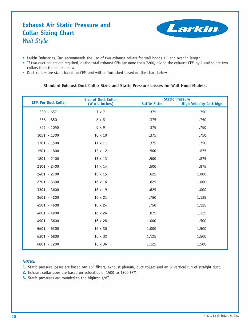
Exhaust Air Static Pressure and Collar Sizing ChartWall Style
• Larkin Industries, Inc. recommends the use of two exhaust collars for wall hoods 12’ and over in length.• If two duct collars are required, or the total exhaust CFM are more than 7200, divide the exhaust CFM by 2 and select two
collars from the chart below.• Duct collars are sized based on CFM and will be furnished based on the chart below.
Standard Exhaust Duct Collar Sizes and Static Pressure Losses for Wall Hood Models.
NOTES:1. Static pressure losses are based on: 16” filters, exhaust plenum, duct collars and an 8’ vertical run of straight duct.2. Exhaust collar sizes are based on velocities of 1500 to 1800 FPM.3. Static pressures are rounded to the highest 1/8”.
40 © 2010 Larkin Industries, Inc.
CFM Per Duct CollarSize of Duct Collar
(W x L inches) Baffle Filter High Velocity Cartridge
550 - 657
658 - 850
851 - 1050
1051 - 1300
1301 - 1500
1501 - 1800
1801 - 2100
2101 - 2400
2401 - 2700
2701 - 3300
3301 - 3600
3601 - 4200
4201 - 4600
4601 - 4900
4901 - 5600
5601 - 6300
6301 - 6800
6801 - 7200
7 x 7
8 x 8
9 x 9
10 x 10
11 x 11
12 x 12
13 x 13
14 x 14
15 x 15
16 x 16
16 x 19
16 x 21
16 x 24
16 x 26
16 x 28
16 x 30
16 x 32
16 x 36
.375
.375
375
.375
.375
.500
.500
.500
.625
.625
.625
.750
.750
.875
1.000
1.000
1.125
1.125
.750
.750
.750
.750
.750
.875
.875
.875
1.000
1.000
1.000
1.125
1.125
1.125
1.500
1.500
1.500
1.500
Static Pressure
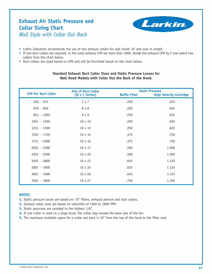
Exhaust Air Static Pressure and Collar Sizing ChartWall Style with Collar Out Back
• Larkin Industries recommends the use of two exhaust collars for wall hoods 10’ and over in length.• If two duct collars are required, or the total exhaust CFM are more than 3600, divide the exhaust CFM by 2 and select two
collars from the chart below.• Duct collars are sized based on CFM and will be furnished based on the chart below.
Standard Exhaust Duct Collar Sizes and Static Pressure Losses for Wall Hood Models with Collar Out the Back of the Hood.
NOTES:1. Static pressure losses are based on: 16” filters, exhaust plenum and duct collars.2. Exhaust collar sizes are based on velocities of 1500 to 1800 FPM.3. Static pressures are rounded to the highest 1/8”.4. If one collar is used on a large hood, the collar may exceed the base size of the fan.5. The maximum available space for a collar out back is 10” from the top of the hood to the filter rack.
41© 2010 Larkin Industries, Inc.
CFM Per Duct CollarSize of Duct Collar
(W x L inches) Baffle Filter High Velocity Cartridge
550 - 675
676 - 850
851 - 1050
1051 - 1250
1251 - 1500
1501 - 1750
1751 - 2000
2001 - 2300
2301 - 2500
2501 - 2800
2801 - 3000
3001 - 3500
3501 - 3600
7 x 7
8 x 8
9 x 9
10 x 10
10 x 12
10 x 14
10 x 16
10 x 17
10 x 20
10 x 21
10 x 24
10 x 26
10 x 27
.250
.250
.250
.250
.250
.375
.375
.500
.500
.625
.625
.625
.750
.625
.625
.625
.625
.625
.750
.750
1.000
1.000
1.125
1.125
1.125
1.250
Static Pressure
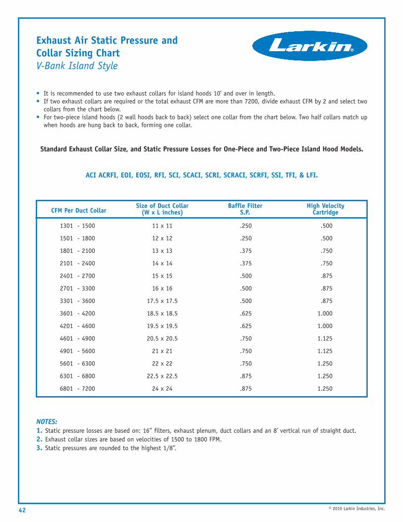
Exhaust Air Static Pressure and Collar Sizing ChartV-Bank Island Style
• It is recommended to use two exhaust collars for island hoods 10’ and over in length.• If two exhaust collars are required or the total exhaust CFM are more than 7200, divide exhaust CFM by 2 and select two
collars from the chart below.• For two-piece island hoods (2 wall hoods back to back) select one collar from the chart below. Two half collars match up
when hoods are hung back to back, forming one collar.
Standard Exhaust Collar Size, and Static Pressure Losses for One-Piece and Two-Piece Island Hood Models.
ACI ACRFI, EOI, EOSI, RFI, SCI, SCACI, SCRI, SCRACI, SCRFI, SSI, TFI, & LFI.
NOTES:1. Static pressure losses are based on: 16” filters, exhaust plenum, duct collars and an 8’ vertical run of straight duct.2. Exhaust collar sizes are based on velocities of 1500 to 1800 FPM.3. Static pressures are rounded to the highest 1/8”.
42 © 2010 Larkin Industries, Inc.
CFM Per Duct CollarSize of Duct Collar
(W x L inches)Baffle Filter
S.P.High Velocity
Cartridge
1301 - 1500
1501 - 1800
1801 - 2100
2101 - 2400
2401 - 2700
2701 - 3300
3301 - 3600
3601 - 4200
4201 - 4600
4601 - 4900
4901 - 5600
5601 - 6300
6301 - 6800
6801 - 7200
11 x 11
12 x 12
13 x 13
14 x 14
15 x 15
16 x 16
17.5 x 17.5
18.5 x 18.5
19.5 x 19.5
20.5 x 20.5
21 x 21
22 x 22
22.5 x 22.5
24 x 24
.250
.250
.375
.375
.500
.500
.500
.625
.625
.750
.750
.750
.875
.875
.500
.500
.750
.750
.875
.875
.875
1.000
1.000
1.125
1.125
1.250
1.250
1.250
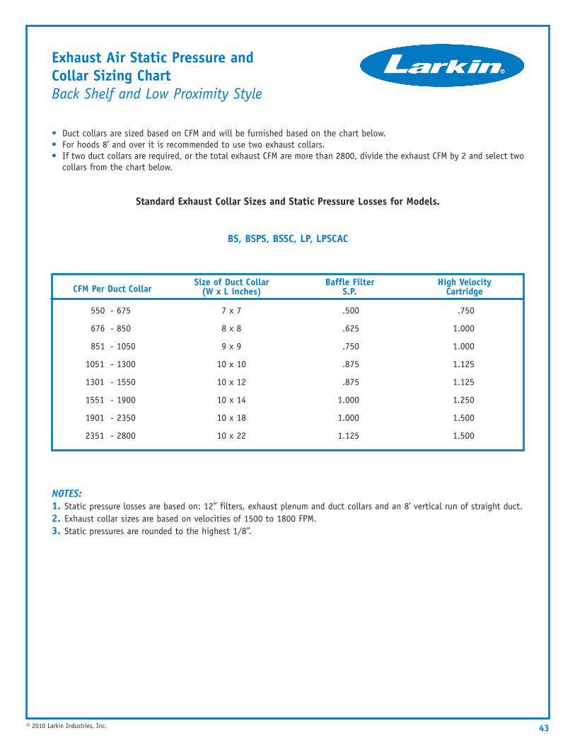
Exhaust Air Static Pressure and Collar Sizing ChartBack Shelf and Low Proximity Style
• Duct collars are sized based on CFM and will be furnished based on the chart below.• For hoods 8’ and over it is recommended to use two exhaust collars.• If two duct collars are required, or the total exhaust CFM are more than 2800, divide the exhaust CFM by 2 and select two
collars from the chart below.
Standard Exhaust Collar Sizes and Static Pressure Losses for Models.
BS, BSPS, BSSC, LP, LPSCAC
NOTES:1. Static pressure losses are based on: 12” filters, exhaust plenum and duct collars and an 8’ vertical run of straight duct.2. Exhaust collar sizes are based on velocities of 1500 to 1800 FPM.3. Static pressures are rounded to the highest 1/8”.
43© 2010 Larkin Industries, Inc.
CFM Per Duct CollarSize of Duct Collar
(W x L inches)Baffle Filter
S.P.High Velocity
Cartridge
550 - 675
676 - 850
851 - 1050
1051 - 1300
1301 - 1550
1551 - 1900
1901 - 2350
2351 - 2800
7 x 7
8 x 8
9 x 9
10 x 10
10 x 12
10 x 14
10 x 18
10 x 22
.500
.625
.750
.875
.875
1.000
1.000
1.125
.750
1.000
1.000
1.125
1.125
1.250
1.500
1.500
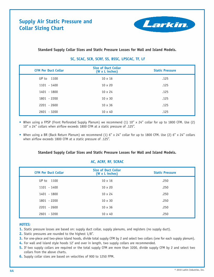
Supply Air Static Pressure and Collar Sizing Chart
Standard Supply Collar Sizes and Static Pressure Losses for Wall and Island Models.
SC, SCAC, SCR, SCRF, SS, BSSC, LPSCAC, TF, LF
• When using a FPSP (Front Perforated Supply Plenum) we recommend (1) 10” x 24” collar for up to 1800 CFM. Use (2)10” x 24” collars when airflow exceeds 1800 CFM at a static pressure of .125”.
• When using a BR (Back Return Plenum) we recommend (1) 6” x 24” collar for up to 1800 CFM. Use (2) 6” x 24” collarswhen airflow exceeds 1800 CFM at a static pressure of .125”.
Standard Supply Collar Sizes and Static Pressure Losses for Wall and Island Models.
AC, ACRF, RF, SCRAC
NOTES:1. Static pressure losses are based on: supply duct collar, supply plenums, and registers (no supply duct).2. Static pressures are rounded to the highest 1/8”.3. For one-piece and two-piece island hoods, divide total supply CFM by 2 and select two collars (one for each supply plenum).4. For wall and island style hoods 12’ and over in length, two supply collars are recommended.5. If two supply collars are required or the total supply CFM are more than 3200, divide supply CFM by 2 and select two
collars from the above charts.6. Supply collar sizes are based on velocities of 900 to 1250 FPM.
44 © 2010 Larkin Industries, Inc.
CFM Per Duct CollarSize of Duct Collar
(W x L inches) Static Pressure
UP to 1100
1101 - 1400
1401 - 1800
1801 - 2200
2201 - 2600
2601 - 3200
10 x 16
10 x 20
10 x 24
10 x 30
10 x 36
10 x 40
.125
.125
.125
.125
.125
.125
CFM Per Duct CollarSize of Duct Collar
(W x L inches) Static Pressure
UP to 1100
1101 - 1400
1401 - 1800
1801 - 2200
2201 - 2600
2601 - 3200
10 x 16
10 x 20
10 x 24
10 x 30
10 x 36
10 x 40
.250
.250
.250
.250
.250
.250
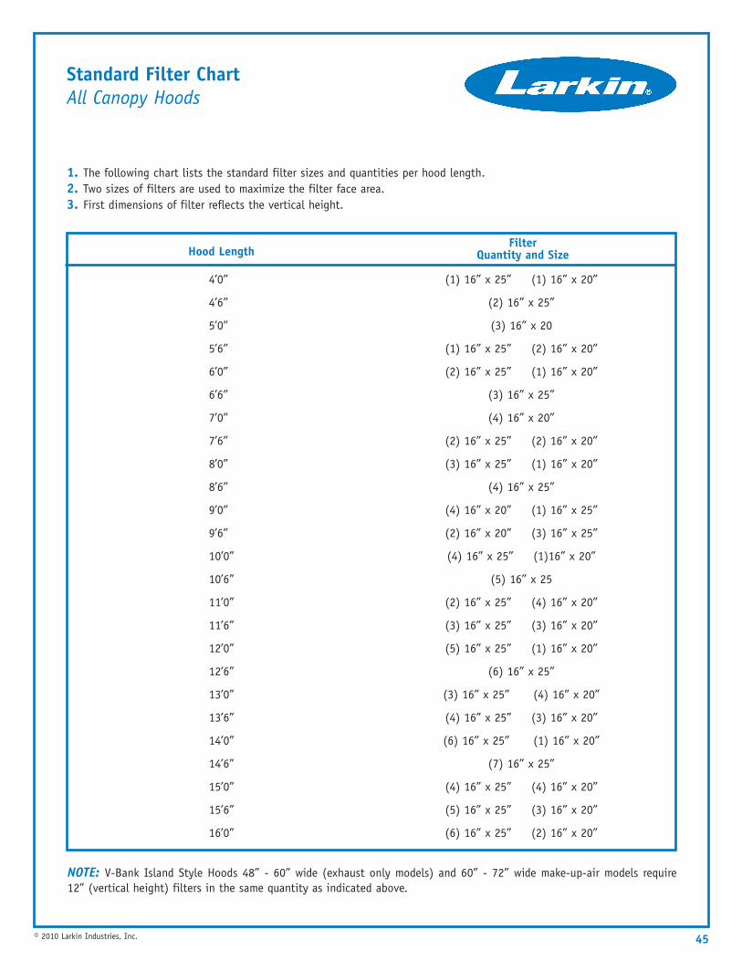
Standard Filter ChartAll Canopy Hoods
1. The following chart lists the standard filter sizes and quantities per hood length.2. Two sizes of filters are used to maximize the filter face area.3. First dimensions of filter reflects the vertical height.
45© 2010 Larkin Industries, Inc.
Hood LengthFilter
Quantity and Size
4’0”
4’6”
5’0”
5’6”
6’0”
6’6”
7’0”
7’6”
8’0”
8’6”
9’0”
9’6”
10’0”
10’6”
11’0”
11’6”
12’0”
12’6”
13’0”
13’6”
14’0”
14’6”
15’0”
15’6”
16’0”
(1) 16” x 25” (1) 16” x 20”
(2) 16” x 25”
(3) 16” x 20
(1) 16” x 25” (2) 16” x 20”
(2) 16” x 25” (1) 16” x 20”
(3) 16” x 25”
(4) 16” x 20”
(2) 16” x 25” (2) 16” x 20”
(3) 16” x 25” (1) 16” x 20”
(4) 16” x 25”
(4) 16” x 20” (1) 16” x 25”
(2) 16” x 20” (3) 16” x 25”
(4) 16” x 25” (1)16” x 20”
(5) 16” x 25
(2) 16” x 25” (4) 16” x 20”
(3) 16” x 25” (3) 16” x 20”
(5) 16” x 25” (1) 16” x 20”
(6) 16” x 25”
(3) 16” x 25” (4) 16” x 20”
(4) 16” x 25” (3) 16” x 20”
(6) 16” x 25” (1) 16” x 20”
(7) 16” x 25”
(4) 16” x 25” (4) 16” x 20”
(5) 16” x 25” (3) 16” x 20”
(6) 16” x 25” (2) 16” x 20”
NOTE: V-Bank Island Style Hoods 48” - 60” wide (exhaust only models) and 60” - 72” wide make-up-air models require12” (vertical height) filters in the same quantity as indicated above.
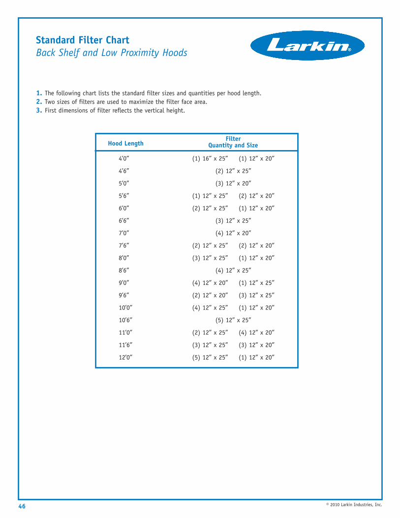
Standard Filter ChartBack Shelf and Low Proximity Hoods
1. The following chart lists the standard filter sizes and quantities per hood length.2. Two sizes of filters are used to maximize the filter face area.3. First dimensions of filter reflects the vertical height.
46 © 2010 Larkin Industries, Inc.
Hood LengthFilter
Quantity and Size
4’0”
4’6”
5’0”
5’6”
6’0”
6’6”
7’0”
7’6”
8’0”
8’6”
9’0”
9’6”
10’0”
10’6”
11’0”
11’6”
12’0”
(1) 16” x 25” (1) 12” x 20”
(2) 12” x 25”
(3) 12” x 20”
(1) 12” x 25” (2) 12” x 20”
(2) 12” x 25” (1) 12” x 20”
(3) 12” x 25”
(4) 12” x 20”
(2) 12” x 25” (2) 12” x 20”
(3) 12” x 25” (1) 12” x 20”
(4) 12” x 25”
(4) 12” x 20” (1) 12” x 25”
(2) 12” x 20” (3) 12” x 25”
(4) 12” x 25” (1) 12” x 20”
(5) 12” x 25”
(2) 12” x 25” (4) 12” x 20”
(3) 12” x 25” (3) 12” x 20”
(5) 12” x 25” (1) 12” x 20”
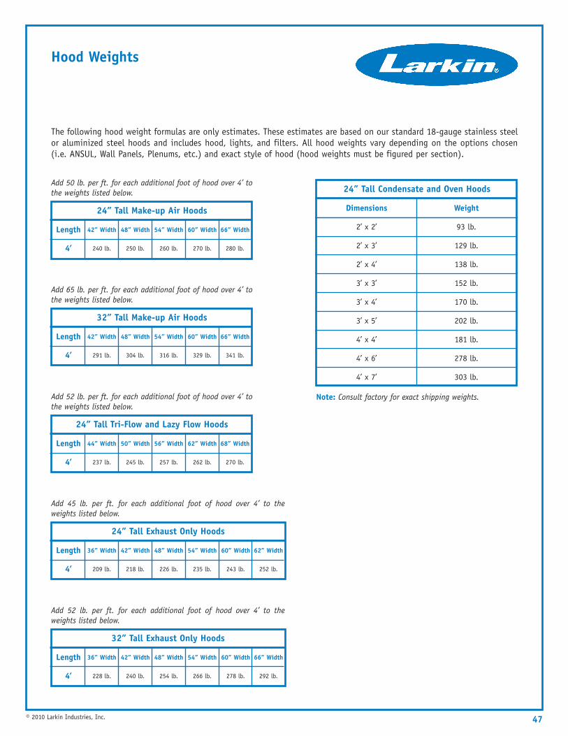
Hood Weights
The following hood weight formulas are only estimates. These estimates are based on our standard 18-gauge stainless steelor aluminized steel hoods and includes hood, lights, and filters. All hood weights vary depending on the options chosen(i.e. ANSUL, Wall Panels, Plenums, etc.) and exact style of hood (hood weights must be figured per section).
47© 2010 Larkin Industries, Inc.
24” Tall Make-up Air Hoods
Length
4’
42” Width
240 lb.
48” Width
250 lb.
54” Width
260 lb.
60” Width
270 lb.
66” Width
280 lb.
Add 50 lb. per ft. for each additional foot of hood over 4’ tothe weights listed below. 24” Tall Condensate and Oven Hoods
Dimensions
2’ x 2’
2’ x 3’
2’ x 4’
3’ x 3’
3’ x 4’
3’ x 5’
4’ x 4’
4’ x 6’
4’ x 7’
Weight
93 lb.
129 lb.
138 lb.
152 lb.
170 lb.
202 lb.
181 lb.
278 lb.
303 lb.
32” Tall Make-up Air Hoods
Length
4’
42” Width
291 lb.
48” Width
304 lb.
54” Width
316 lb.
60” Width
329 lb.
66” Width
341 lb.
Add 65 lb. per ft. for each additional foot of hood over 4’ tothe weights listed below.
24” Tall Tri-Flow and Lazy Flow Hoods
Length
4’
44” Width
237 lb.
50” Width
245 lb.
56” Width
257 lb.
62” Width
262 lb.
68” Width
270 lb.
Add 52 lb. per ft. for each additional foot of hood over 4’ tothe weights listed below.
24” Tall Exhaust Only Hoods
Length
4’
36” Width
209 lb.
42” Width
218 lb.
48” Width
226 lb.
54” Width
235 lb.
60” Width
243 lb.
62” Width
252 lb.
Add 45 lb. per ft. for each additional foot of hood over 4’ to theweights listed below.
32” Tall Exhaust Only Hoods
Length
4’
36” Width
228 lb.
42” Width
240 lb.
48” Width
254 lb.
54” Width
266 lb.
60” Width
278 lb.
66” Width
292 lb.
Add 52 lb. per ft. for each additional foot of hood over 4’ to theweights listed below.
Note: Consult factory for exact shipping weights.
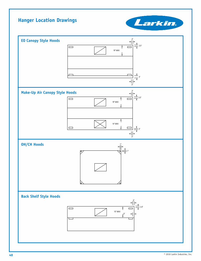
Hanger Location Drawings
48 © 2010 Larkin Industries, Inc.
Back Shelf Style Hoods
OH/CH Hoods
Make-Up Air Canopy Style Hoods
EO Canopy Style Hoods
49© 2010 Larkin Industries, Inc.
Exhaust Fans
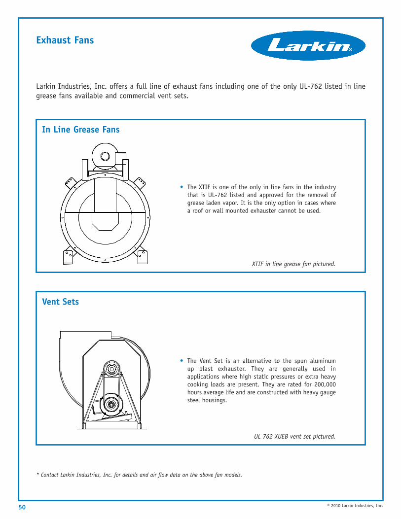
Exhaust Fans
50 © 2010 Larkin Industries, Inc.
In Line Grease Fans
Vent Sets
Larkin Industries, Inc. offers a full line of exhaust fans including one of the only UL-762 listed in linegrease fans available and commercial vent sets.
* Contact Larkin Industries, Inc. for details and air flow data on the above fan models.
• The XTIF is one of the only in line fans in the industrythat is UL-762 listed and approved for the removal ofgrease laden vapor. It is the only option in cases wherea roof or wall mounted exhauster cannot be used.
XTIF in line grease fan pictured.
• The Vent Set is an alternative to the spun aluminumup blast exhauster. They are generally used inapplications where high static pressures or extra heavycooking loads are present. They are rated for 200,000hours average life and are constructed with heavy gaugesteel housings.
UL 762 XUEB vent set pictured.
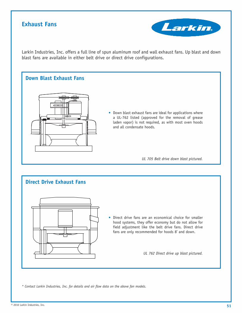
Exhaust Fans
51© 2010 Larkin Industries, Inc.
Down Blast Exhaust Fans
Direct Drive Exhaust Fans
Larkin Industries, Inc. offers a full line of spun aluminum roof and wall exhaust fans. Up blast and downblast fans are available in either belt drive or direct drive configurations.
* Contact Larkin Industries, Inc. for details and air flow data on the above fan models.
• Down blast exhaust fans are ideal for applications wherea UL-762 listed (approved for the removal of greaseladen vapor) is not required, as with most oven hoodsand all condensate hoods.
UL 705 Belt drive down blast pictured.
• Direct drive fans are an economical choice for smallerhood systems, they offer economy but do not allow forfield adjustment like the belt drive fans. Direct drivefans are only recommended for hoods 8’ and down.
UL 762 Direct drive up blast pictured.
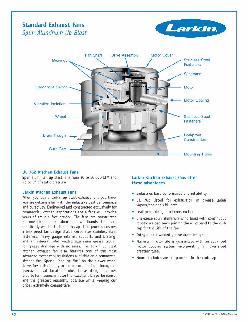
Standard Exhaust FansSpun Aluminum Up Blast
52 © 2010 Larkin Industries, Inc.
UL 762 Kitchen Exhaust FansSpun aluminum up blast fans from 80 to 30,000 CFM andup to 5” of static pressure
Larkin Kitchen Exhaust FansWhen you buy a Larkin up blast exhaust fan, you knowyou are getting a fan with the industry’s best performanceand durability. Engineered and constructed exclusively forcommercial kitchen applications these fans will provideyears of trouble free service. The fans are constructedof one-piece spun aluminum windbands that arerobotically welded to the curb cap. This process ensuresa leak proof fan design that incorporates stainless steelfasteners, heavy gauge internal supports and bracing,and an integral solid welded aluminum grease troughfor grease drainage with no mess. The Larkin up blastkitchen exhaust fan also features one of the mostadvanced motor cooling designs available on a commercialkitchen fan. Special “cooling fins” on the blower wheeldraws fresh air directly to the motor openings through anoversized oval breather tube. These design featuresprovide for maximum motor life, excellent fan performance,and the greatest reliability possible while keeping ourprices extremely competitive.
Larkin Kitchen Exhaust Fans offer these advantages
• Industries best performance and reliability
• UL 762 listed for exhaustion of grease ladenvapors/cooking effluents
• Leak proof design and construction
• One-piece spun aluminum wind band with continuousrobotic welded seem joining the wind band to the curbcap for the life of the fan
• Integral sold welded grease drain trough
• Maximum motor life is guaranteed with an advancedmotor cooling system incorporating an over-sizedbreather tube.
• Mounting holes are pre-punched in the curb cap
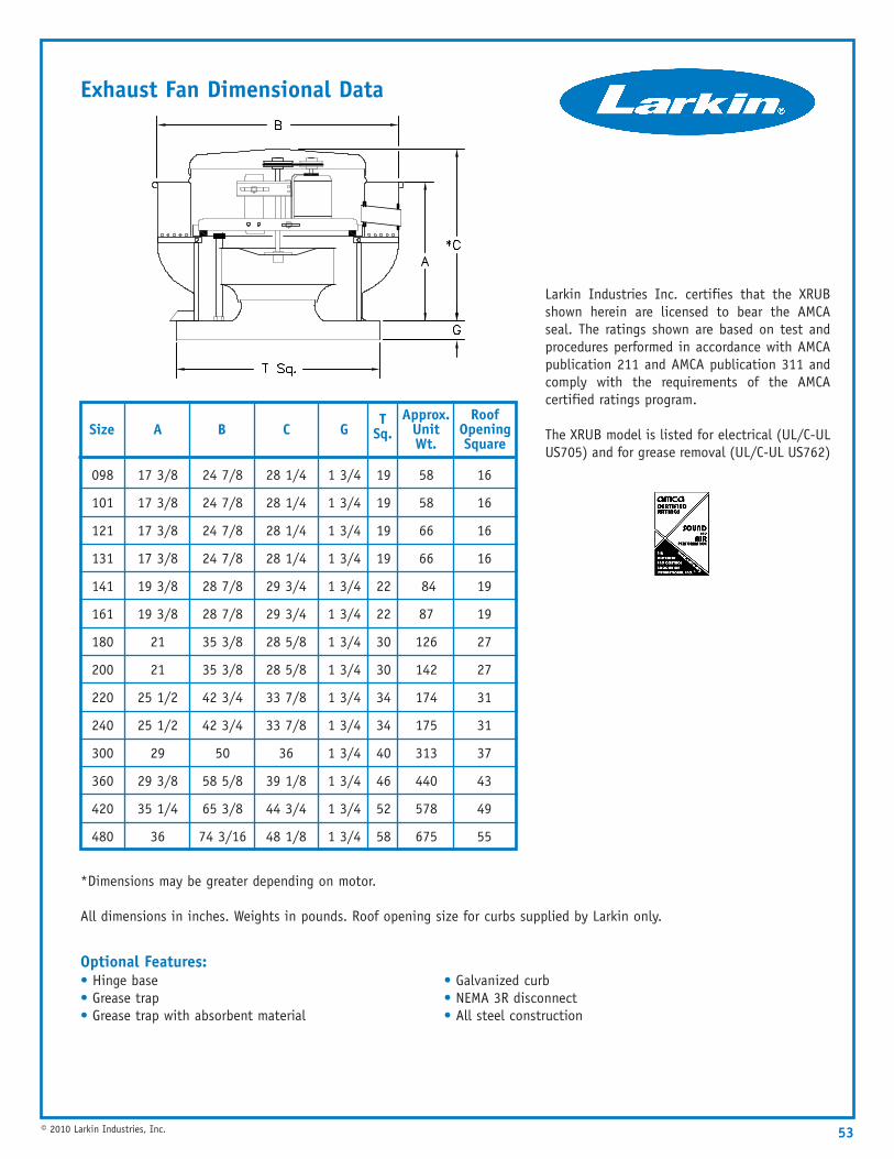
Exhaust Fan Dimensional Data
Optional Features: • Hinge base• Grease trap• Grease trap with absorbent material
Standard Construction Features: • Galvanized curb• NEMA 3R disconnect• All steel construction
*Dimensions may be greater depending on motor.
All dimensions in inches. Weights in pounds. Roof opening size for curbs supplied by Larkin only.
53© 2010 Larkin Industries, Inc.
SizeT
Sq.Approx.
Unit Wt.
098
101
121
131
141
161
180
200
220
240
300
360
420
480
Larkin Industries Inc. certifies that the XRUBshown herein are licensed to bear the AMCAseal. The ratings shown are based on test andprocedures performed in accordance with AMCApublication 211 and AMCA publication 311 andcomply with the requirements of the AMCAcertified ratings program.
The XRUB model is listed for electrical (UL/C-ULUS705) and for grease removal (UL/C-UL US762)
A
17 3/8
17 3/8
17 3/8
17 3/8
19 3/8
19 3/8
21
21
25 1/2
25 1/2
29
29 3/8
35 1/4
36
B
24 7/8
24 7/8
24 7/8
24 7/8
28 7/8
28 7/8
35 3/8
35 3/8
42 3/4
42 3/4
50
58 5/8
65 3/8
74 3/16
C
28 1/4
28 1/4
28 1/4
28 1/4
29 3/4
29 3/4
28 5/8
28 5/8
33 7/8
33 7/8
36
39 1/8
44 3/4
48 1/8
58
58
66
66
84
87
126
142
174
175
313
440
578
675
RoofOpening Square
16
16
16
16
19
19
27
27
31
31
37
43
49
55
G
1 3/4
1 3/4
1 3/4
1 3/4
1 3/4
1 3/4
1 3/4
1 3/4
1 3/4
1 3/4
1 3/4
1 3/4
1 3/4
1 3/4
19
19
19
19
22
22
30
30
34
34
40
46
52
58
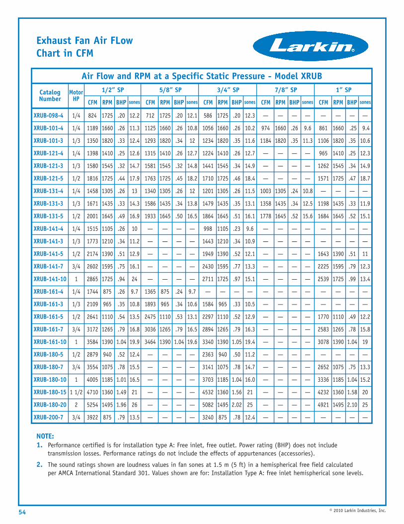
Exhaust Fan Air FLow Chart in CFM
NOTE: 1. Performance certified is for installation type A: Free inlet, free outlet. Power rating (BHP) does not include
transmission losses. Performance ratings do not include the effects of appurtenances (accessories).
2. The sound ratings shown are loudness values in fan sones at 1.5 m (5 ft) in a hemispherical free field calculated per AMCA International Standard 301. Values shown are for: Installation Type A: free inlet hemispherical sone levels.
54 © 2010 Larkin Industries, Inc.
1/2” SP
824
1189
1350
1398
1580
1816
1458
1671
2001
1515
1773
2174
2602
2865
1744
2109
2641
3172
3584
2879
3554
4005
4710
5254
3922
1725
1660
1820
1410
1545
1725
1305
1435
1645
1105
1210
1390
1595
1725
875
965
1110
1265
1390
940
1075
1185
1360
1495
875
.20
.26
.33
.25
.32
.44
.26
.33
.49
.26
.34
.51
.75
.94
.26
.35
.54
.79
1.04
.52
.78
1.01
1.49
1.96
.79
MotorHP
1/4
1/4
1/3
1/4
1/3
1/2
1/4
1/3
1/2
1/4
1/3
1/2
3/4
1
1/4
1/3
1/2
3/4
1
1/2
3/4
1
1 1/2
2
3/4
CatalogNumber
XRUB-098-4
XRUB-101-4
XRUB-101-3
XRUB-121-4
XRUB-121-3
XRUB-121-5
XRUB-131-4
XRUB-131-3
XRUB-131-5
XRUB-141-4
XRUB-141-3
XRUB-141-5
XRUB-141-7
XRUB-141-10
XRUB-161-4
XRUB-161-3
XRUB-161-5
XRUB-161-7
XRUB-161-10
XRUB-180-5
XRUB-180-7
XRUB-180-10
XRUB-180-15
XRUB-180-20
XRUB-200-7
Air Flow and RPM at a Specific Static Pressure - Model XRUB
CFM RPM BHP
12.2
11.3
12.4
12.6
14.7
17.9
13
14.3
16.9
10
11.2
12.9
16.1
24
9.7
10.8
13.5
16.8
19.9
12.4
15.5
16.5
21
26
13.5
sones
5/8” SP
712
1125
1293
1315
1581
1763
1340
1586
1933
—
—
—
—
—
1365
1893
2475
3036
3464
—
—
—
—
—
—
1725
1660
1820
1410
1545
1725
1305
1435
1645
—
—
—
—
—
875
965
1110
1265
1390
—
—
—
—
—
—
.20
.26
.34
.26
.32
.45
.26
.34
.50
—
—
—
—
—
.24
.34
.53
.79
1.04
—
—
—
—
—
—
CFM RPM BHP
12.1
10.8
12
12.7
14.8
18.2
12
13.8
16.5
—
—
—
—
—
9.7
10.6
13.1
16.5
19.6
—
—
—
—
—
—
sones
3/4” SP
586
1056
1234
1224
1441
1710
1201
1479
1864
998
1443
1949
2430
2711
—
1584
2297
2894
3340
2363
3141
3703
4532
5082
3240
1725
1660
1820
1410
1545
1725
1305
1435
1645
1105
1210
1390
1595
1725
—
965
1110
1265
1390
940
1075
1185
1360
1495
875
.20
.26
.35
.26
.34
.46
.26
.35
.51
.23
.34
.52
.77
.97
—
.33
.52
.79
1.05
.50
.78
1.04
1.56
2.02
.78
CFM RPM BHP
12.3
10.2
11.6
12.7
14.9
18.4
11.5
13.1
16.1
9.6
10.9
12.1
13.3
15.1
—
10.5
12.9
16.3
19.4
11.2
14.7
16.0
21
25
12.4
sones
7/8” SP
—
974
1184
—
—
—
1003
1358
1778
—
—
—
—
—
—
—
—
—
—
—
—
—
—
—
—
—
1660
1820
—
—
—
1305
1435
1645
—
—
—
—
—
—
—
—
—
—
—
—
—
—
—
—
—
.26
.35
—
—
—
.24
.34
.52
—
—
—
—
—
—
—
—
—
—
—
—
—
—
—
—
CFM RPM BHP
—
9.6
11.3
—
—
—
10.8
12.5
15.6
—
—
—
—
—
—
—
—
—
—
—
—
—
—
—
—
sones
1” SP
—
861
1106
965
1262
1571
—
1198
1684
—
—
1643
2225
2539
—
—
1770
2583
3078
—
2652
3336
4232
4921
—
—
1660
1820
1410
1545
1725
—
1435
1645
—
—
1390
1595
1725
—
—
1110
1265
1390
—
1075
1185
1360
1495
—
—
.25
.35
.25
.34
.47
—
.33
.52
—
—
.51
.79
.99
—
—
.49
.78
1.04
—
.75
1.04
1.58
2.10
—
CFM RPM BHP
—
9.4
10.6
12.3
14.9
18.7
—
11.9
15.1
—
—
11
12.3
13.4
—
—
12.2
15.8
19
—
13.3
15.2
20
25
—
sones
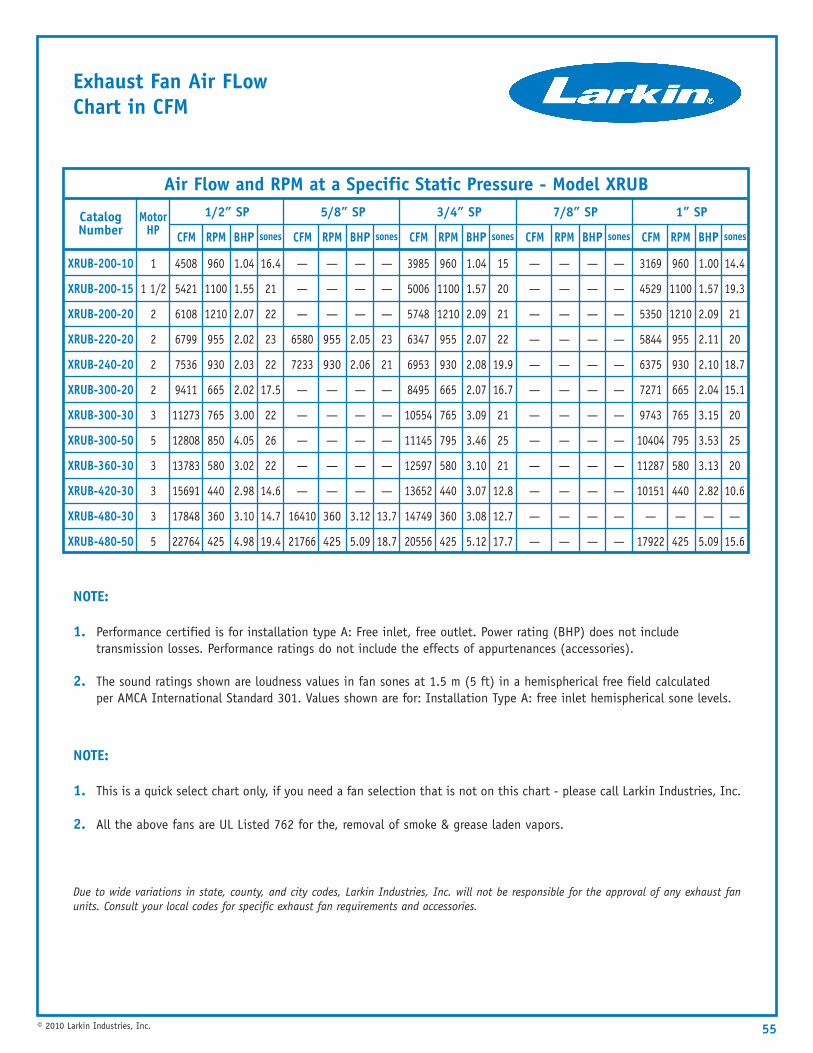
Exhaust Fan Air FLow Chart in CFM
55© 2010 Larkin Industries, Inc.
1/2” SP
4508
5421
6108
6799
7536
9411
11273
12808
13783
15691
17848
22764
960
1100
1210
955
930
665
765
850
580
440
360
425
1.04
1.55
2.07
2.02
2.03
2.02
3.00
4.05
3.02
2.98
3.10
4.98
MotorHP
1
1 1/2
2
2
2
2
3
5
3
3
3
5
CatalogNumber
XRUB-200-10
XRUB-200-15
XRUB-200-20
XRUB-220-20
XRUB-240-20
XRUB-300-20
XRUB-300-30
XRUB-300-50
XRUB-360-30
XRUB-420-30
XRUB-480-30
XRUB-480-50
Air Flow and RPM at a Specific Static Pressure - Model XRUB
CFM RPM BHP
NOTE:
1. This is a quick select chart only, if you need a fan selection that is not on this chart - please call Larkin Industries, Inc.
2. All the above fans are UL Listed 762 for the, removal of smoke & grease laden vapors.
Due to wide variations in state, county, and city codes, Larkin Industries, Inc. will not be responsible for the approval of any exhaust fanunits. Consult your local codes for specific exhaust fan requirements and accessories.
NOTE:
1. Performance certified is for installation type A: Free inlet, free outlet. Power rating (BHP) does not include transmission losses. Performance ratings do not include the effects of appurtenances (accessories).
2. The sound ratings shown are loudness values in fan sones at 1.5 m (5 ft) in a hemispherical free field calculated per AMCA International Standard 301. Values shown are for: Installation Type A: free inlet hemispherical sone levels.
16.4
21
22
23
22
17.5
22
26
22
14.6
14.7
19.4
sones
5/8” SP
—
—
—
6580
7233
—
—
—
—
—
16410
21766
—
—
—
955
930
—
—
—
—
—
360
425
—
—
—
2.05
2.06
—
—
—
—
—
3.12
5.09
CFM RPM BHP
—
—
—
23
21
—
—
—
—
—
13.7
18.7
sones
3/4” SP
3985
5006
5748
6347
6953
8495
10554
11145
12597
13652
14749
20556
960
1100
1210
955
930
665
765
795
580
440
360
425
1.04
1.57
2.09
2.07
2.08
2.07
3.09
3.46
3.10
3.07
3.08
5.12
CFM RPM BHP
15
20
21
22
19.9
16.7
21
25
21
12.8
12.7
17.7
sones
7/8” SP
—
—
—
—
—
—
—
—
—
—
—
—
—
—
—
—
—
—
—
—
—
—
—
—
—
—
—
—
—
—
—
—
—
—
—
—
CFM RPM BHP
—
—
—
—
—
—
—
—
—
—
—
—
sones
1” SP
3169
4529
5350
5844
6375
7271
9743
10404
11287
10151
—
17922
960
1100
1210
955
930
665
765
795
580
440
—
425
1.00
1.57
2.09
2.11
2.10
2.04
3.15
3.53
3.13
2.82
—
5.09
CFM RPM BHP
14.4
19.3
21
20
18.7
15.1
20
25
20
10.6
—
15.6
sones
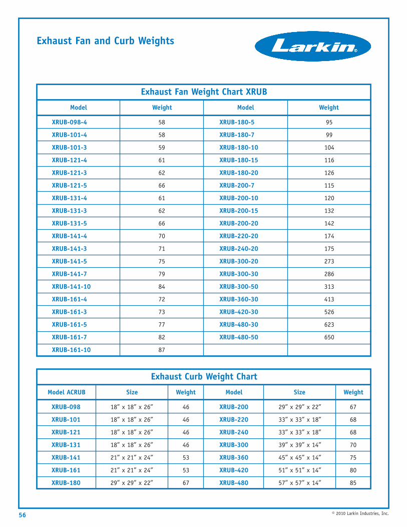
Exhaust Fan and Curb Weights
56 © 2010 Larkin Industries, Inc.
Weight
95
99
104
116
126
115
120
132
142
174
175
273
286
313
413
526
623
650
Model
XRUB-180-5
XRUB-180-7
XRUB-180-10
XRUB-180-15
XRUB-180-20
XRUB-200-7
XRUB-200-10
XRUB-200-15
XRUB-200-20
XRUB-220-20
XRUB-240-20
XRUB-300-20
XRUB-300-30
XRUB-300-50
XRUB-360-30
XRUB-420-30
XRUB-480-30
XRUB-480-50
Weight
58
58
59
61
62
66
61
62
66
70
71
75
79
84
72
73
77
82
87
Model
XRUB-098-4
XRUB-101-4
XRUB-101-3
XRUB-121-4
XRUB-121-3
XRUB-121-5
XRUB-131-4
XRUB-131-3
XRUB-131-5
XRUB-141-4
XRUB-141-3
XRUB-141-5
XRUB-141-7
XRUB-141-10
XRUB-161-4
XRUB-161-3
XRUB-161-5
XRUB-161-7
XRUB-161-10
Exhaust Fan Weight Chart XRUB
Weight
67
68
68
70
75
80
85
Size
29” x 29” x 22”
33” x 33” x 18”
33” x 33” x 18”
39” x 39” x 14”
45” x 45” x 14”
51” x 51” x 14”
57” x 57” x 14”
Model
XRUB-200
XRUB-220
XRUB-240
XRUB-300
XRUB-360
XRUB-420
XRUB-480
Weight
46
46
46
46
53
53
67
Size
18” x 18” x 26”
18” x 18” x 26”
18” x 18” x 26”
18” x 18” x 26”
21” x 21” x 24”
21” x 21” x 24”
29” x 29” x 22”
Model ACRUB
XRUB-098
XRUB-101
XRUB-121
XRUB-131
XRUB-141
XRUB-161
XRUB-180
Exhaust Curb Weight Chart
57© 2010 Larkin Industries, Inc.
Supply Fans
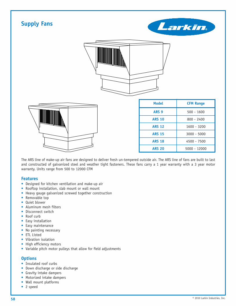
Supply Fans
The ARS line of make-up air fans are designed to deliver fresh un-tempered outside air. The ARS line of fans are built to lastand constructed of galvanized steel and weather tight fasteners. These fans carry a 1 year warranty with a 3 year motorwarranty. Units range from 500 to 12000 CFM
Features• Designed for kitchen ventilation and make-up air• Rooftop installation, slab mount or wall mount• Heavy gauge galvanized screwed together construction• Removable top• Quiet blower• Aluminum mesh filters• Disconnect switch• Roof curb• Easy installation• Easy maintenance• No painting necessary• ETL Listed• Vibration isolation• High efficiency motors• Variable pitch motor pulleys that allow for field adjustments
Options• Insulated roof curbs• Down discharge or side discharge• Gravity intake dampers• Motorized intake dampers• Wall mount platforms• 2 speed
58 © 2010 Larkin Industries, Inc.
CFM Range
500 - 1600
800 - 2400
1600 - 3200
3000 - 5000
4500 - 7500
5000 - 12000
Model
ARS 9
ARS 10
ARS 12
ARS 15
ARS 18
ARS 20
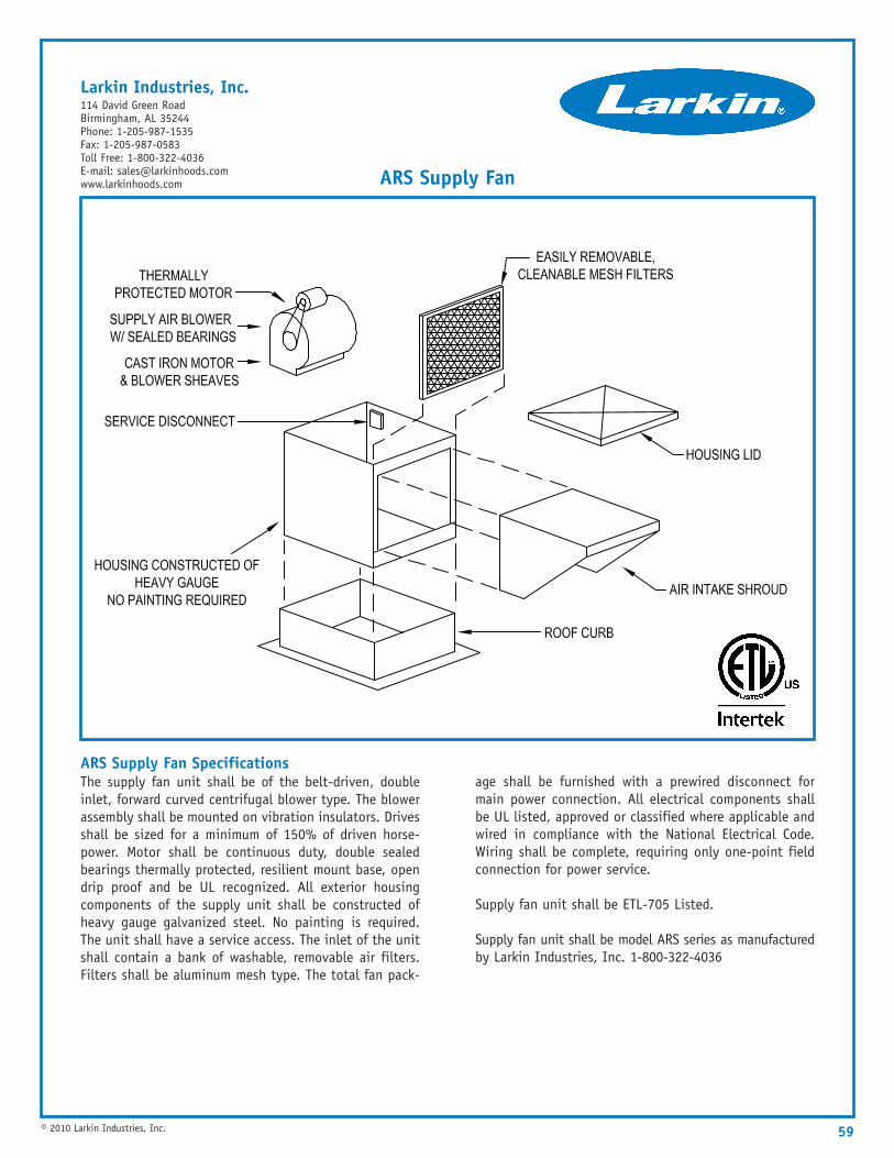
59© 2010 Larkin Industries, Inc.
ARS Supply Fan SpecificationsThe supply fan unit shall be of the belt-driven, doubleinlet, forward curved centrifugal blower type. The blowerassembly shall be mounted on vibration insulators. Drivesshall be sized for a minimum of 150% of driven horse-power. Motor shall be continuous duty, double sealedbearings thermally protected, resilient mount base, opendrip proof and be UL recognized. All exterior housingcomponents of the supply unit shall be constructed ofheavy gauge galvanized steel. No painting is required.The unit shall have a service access. The inlet of the unitshall contain a bank of washable, removable air filters.Filters shall be aluminum mesh type. The total fan pack-
age shall be furnished with a prewired disconnect formain power connection. All electrical components shallbe UL listed, approved or classified where applicable andwired in compliance with the National Electrical Code.Wiring shall be complete, requiring only one-point fieldconnection for power service.
Supply fan unit shall be ETL-705 Listed.
Supply fan unit shall be model ARS series as manufacturedby Larkin Industries, Inc. 1-800-322-4036
ARS Supply Fan
Larkin Industries, Inc.114 David Green RoadBirmingham, AL 35244Phone: 1-205-987-1535Fax: 1-205-987-0583Toll Free: 1-800-322-4036E-mail: [email protected]
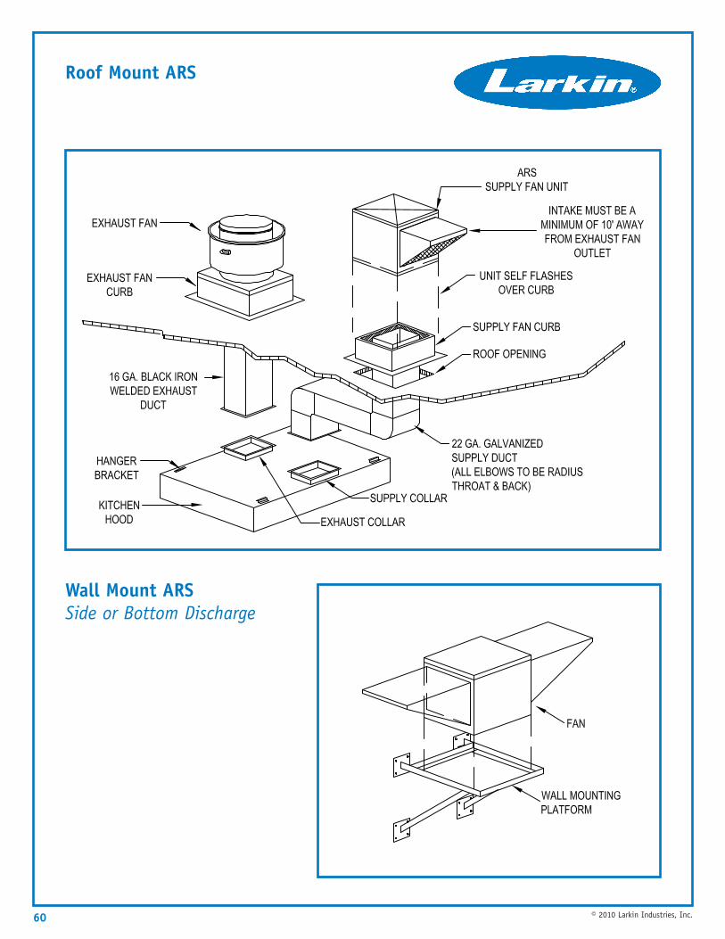
60 © 2010 Larkin Industries, Inc.
Roof Mount ARS
Wall Mount ARSSide or Bottom Discharge
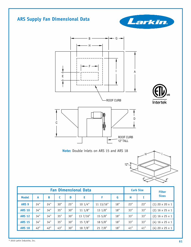
61© 2010 Larkin Industries, Inc.
ARS Supply Fan Dimensional Data
Filter Sizes
(1) 20 x 20 x 1
(2) 16 x 25 x 1
(2) 16 x 25 x 1
(4) 16 x 25 x 1
(4) 20 x 25 x 1
24”
34”
34”
34”
42”
AModel
ARS 9
ARS 10
ARS 12
ARS 15
ARS 18
24”
34”
34”
34”
42”
B
30”
35”
35”
35”
43”
C
25”
30”
30”
30”
30”
D
10 1/4”
11 1/8”
13 7/16”
15 7/8”
18 7/8”
E
11 13/16”
13 1/8”
15 5/8”
18 5/8”
21 7/8”
F
18”
18”
18”
18”
18”
G
23”
33”
33”
33”
41”
H
23”
33”
33”
33”
41”
I
Fan Dimensional Data Curb Size
Note: Double inlets on ARS 15 and ARS 18
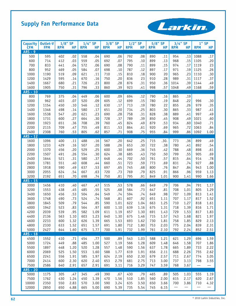
62 © 2010 Larkin Industries, Inc.
Supply Fan Performance Data
CapacityCFM
500600700800
1000120014001600
80010001200140016001800200022002400
160018002000220024002600280030003200
30003200340036003800400042004400460048005000
4500500055006000650070007500
50007500
1000012000
Outlet-VFPM
1/8” SPRPM HP
595714833952
1190142916671905
769962
1154134615381731192321152308
109612331370150716441781191820552192
14561553165017481845194220392136223323302427
1552172418972069224124142586
1175176223502850
.02
.03
.04
.05
.09
.14
.21
.31
.04
.07
.10
.14
.20
.27
.36
.47
.53
.11
.16
.20
.26
.31
.40
.49
.54
.70
.40
.45
.53
.73
.79
.83
.951.101.321.521.60
.71
.881.201.501.912.302.91
.471.242.834.88
402412441469519595680750
375403450498547600651709760
400429456491521551590624651
410438456490509523539563600633644
410449448525556600640
305430550650
.04
.05
.06
.07
.11
.16
.23
.33
.06
.09
.12
.17
.23
.30
.39
.49
.62
.16
.20
.25
.30
.37
.44
.53
.63
.74
,47.55.64.74.85.97
1.091.231.391.571.77
.771.001.281.601.972.402.91
.491.393.005.00
558559572584621670726796
449520546580621664708755805
488507529554580608637667698
467485504524544564582603626651675
454485520553585620657
345450570665
.06
.07
.08
.10
.15
.20
.28
.39
.09
.12
.17
.20
.28
.37
.45
.53
.71
.20
.26
.30
.38
.44
.51
.65
.73
.81
.53
.68
.74
.811.011.101.191.301.531.801.91
.891.191.481.772.192.793.11
.671.563.245.39
690692690698710750800860
600605630651690728760811857
567588600624648660697720750
515525549568590600611640665691700
500527557588624653691
390470590690
.08
.10
.11
.12
.1823.31.41
.12
.15
.19
.25
.31
.39
.49
.61
.75
.25
.30
.36
.43
.50
.59
.68
.79
.91
.66
.73
.74
.921.041.161.301.461.621.801.99
1.031.281.561.912.302.753.29
.791.853.505.54
792795790787810836876923
694699713734758789824864908
642653669685702723745769795
578584594607622639657675693712732
543566590619650681716
430510635735
.11
.13
.15
.1720.28.36.57
.16
.1922.30.38.45.53.69.84
.30..38.42.50.57.69.76.91
1.01
.79
.81
.981.111.251.311.431.571.812.032.10
1.211.481.782.112.573.003.59
.892.003.666.15
890899899897900910950998
790780780803828850879920955
715722745750761773800825849
649647649651663675691715730753761
588609637656679713747
465560650745
.13
.15
.17
.19
.23
.31
.39
.49
.19
.22
.26
.33
.41
.49
.60
.72
.86
.36
.41
.48
.55
.64
.74
.84
.961.41
.941.011.091.171.271.391.531.681.852.042.24
1.291.581.892.262.673.133.67
1.032.173.86—
954968974971965989
10141048
865848855865889908934965999
773780788799815831847866900
706708707707710718729743758775792
621646665688711737768
505615700—
.17
.2023.26.30.37.49.59
.30
.35
.41
.49
.60
.71
.841.00
.49
.54
.61
.69
.78
.881.001.131.66
1,171.291.411.521.611.711.831.972.132.312.51
1.591.862.222.623.053.55—
1.192.674.32—
10881105111911251110111711441168
996979987997
1021104010631092
899892898905914927943959990
791805813817818816817821829839852
696707733755774798—
555620710—
1/4” SPRPM HP
3/8” SPRPM HP
1/2” SPRPM HP
5/8” SPRPM HP
3/4” SPRPM HP
1” SPRPM HP
ARS - 9
ARS - 10
ARS - 12
ARS - 15
ARS - 18
ARS - 20
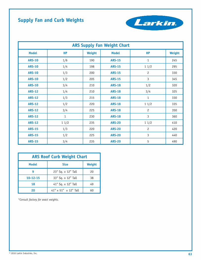
Supply Fan and Curb Weights
63© 2010 Larkin Industries, Inc.
Weight
245
295
330
345
320
325
330
335
350
360
410
420
440
490
HP
1
1 1/2
2
3
1/2
3/4
1
1 1/2
2
3
1 1/2
2
3
5
Model
ARS-15
ARS-15
ARS-15
ARS-15
ARS-18
ARS-18
ARS-18
ARS-18
ARS-18
ARS-18
ARS-20
ARS-20
ARS-20
ARS-20
Weight
190
198
200
205
210
210
215
220
225
230
235
220
225
235
HP
1/6
1/4
1/3
1/2
3/4
1/4
1/3
1/2
3/4
1
1 1/2
1/3
1/2
3/4
Model
ARS-1O
ARS-1O
ARS-1O
ARS-1O
ARS-1O
ARS-12
ARS-12
ARS-12
ARS-12
ARS-12
ARS-12
ARS-15
ARS-15
ARS-15
ARS Supply Fan Weight Chart
Weight
20
38
49
60
Size
23“ Sq. x 12” Tall
33“ Sq. x 12” Tall
41“ Sq. x 12” Tall
41“ x 51” x 12” Tall
Model
9
10-12-15
18
20
ARS Roof Curb Weight Chart
*Consult factory for exact weights.
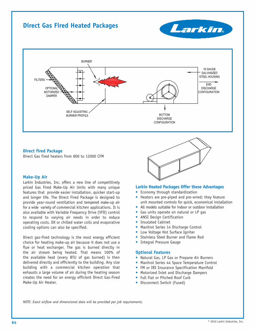
64
NOTE: Exact airflow and dimensional data will be provided per job requirements.
© 2010 Larkin Industries, Inc.
Direct Gas Fired Heated Packages
Direct fired PackageDirect Gas fired heaters from 800 to 12000 CFM
Make-Up AirLarkin Industries, Inc. offers a new line of competitivelypriced Gas Fired Make-Up Air Units with many uniquefeatures that provide easier installation, quicker start-upand longer life. The Direct Fired Package is designed toprovide year-round ventilation and tempered make-up airfor a wide variety of commercial kitchen applications. It isalso available with Variable Frequency Drive (VFD) controlto respond to varying air needs in order to reduceoperating costs. DX or chilled water coils and evaporativecooling options can also be specified.
Direct gas-fired technology is the most energy efficientchoice for heating make-up air because it does not use aflue or heat exchanger. The gas is burned directly inthe air stream being heated. That means 100% ofthe available heat (every BTU of gas burned) is thendelivered directly and efficiently to the building. Any sizebuilding with a commercial kitchen operation thatexhausts a large volume of air during the heating seasoncreates the need for an energy efficient Direct Gas-FiredMake-Up Air Heater.
Larkin Heated Packages Offer these Advantages• Economy through standardization• Heaters are pre-piped and pre-wired; they feature
unit mounted controls for quick, economical installation• All models suitable for indoor or outdoor installation• Gas units operate on natural or LP gas• ANSI Design Certification• Insulated Cabinet• Maxitrol Series 14 Discharge Control• Low Voltage Hot Surface Igniter• Stainless Steel Burner and Flame Rod• Integral Pressure Gauge
Optional Features• Natural Gas, LP Gas or Propane Air Burners• Maxitrol Series 44 Space Temperature Control• FM or IRI Insurance Specification Manifold• Motorized Inlet and Discharge Dampers• Full Flat or Pitched Roof Curb• Disconnect Switch (Fused)
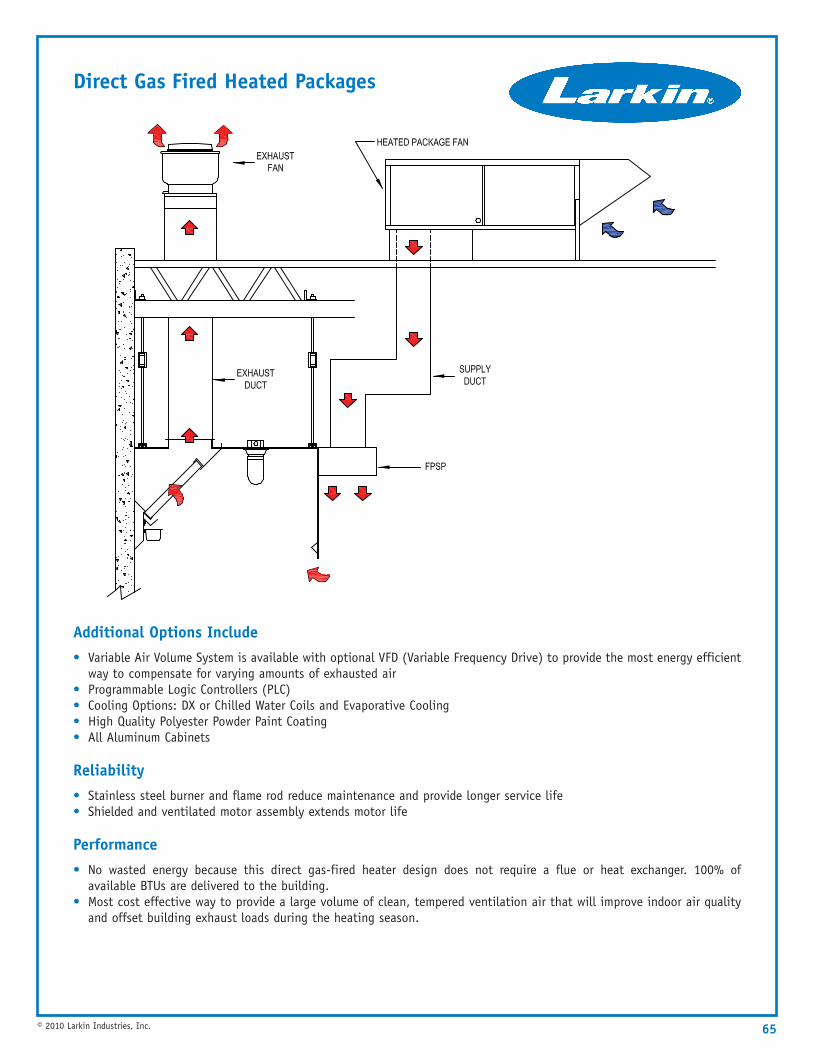
Additional Options Include• Variable Air Volume System is available with optional VFD (Variable Frequency Drive) to provide the most energy efficient
way to compensate for varying amounts of exhausted air• Programmable Logic Controllers (PLC)• Cooling Options: DX or Chilled Water Coils and Evaporative Cooling• High Quality Polyester Powder Paint Coating• All Aluminum Cabinets
Reliability• Stainless steel burner and flame rod reduce maintenance and provide longer service life• Shielded and ventilated motor assembly extends motor life
Performance• No wasted energy because this direct gas-fired heater design does not require a flue or heat exchanger. 100% of
available BTUs are delivered to the building.• Most cost effective way to provide a large volume of clean, tempered ventilation air that will improve indoor air quality
and offset building exhaust loads during the heating season.
65© 2010 Larkin Industries, Inc.
Direct Gas Fired Heated Packages
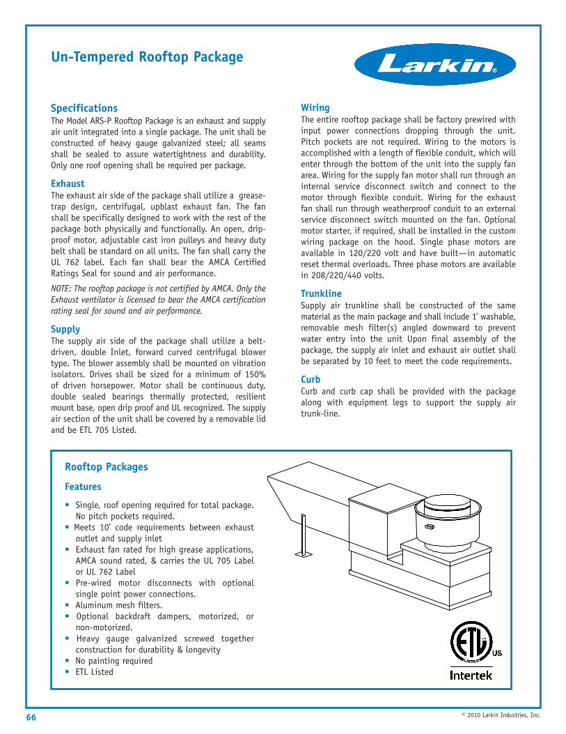
66 © 2010 Larkin Industries, Inc.
Un-Tempered Rooftop Package
SpecificationsThe Model ARS-P Rooftop Package is an exhaust and supplyair unit integrated into a single package. The unit shall beconstructed of heavy gauge galvanized steel; all seamsshall be sealed to assure watertightness and durability.Only one roof opening shall be required per package.
Exhaust The exhaust air side of the package shall utilize a grease-trap design, centrifugal, upblast exhaust fan. The fanshall be specifically designed to work with the rest of thepackage both physically and functionally. An open, drip-proof motor, adjustable cast iron pulleys and heavy dutybelt shall be standard on all units. The fan shall carry theUL 762 label. Each fan shall bear the AMCA CertifiedRatings Seal for sound and air performance.
NOTE: The rooftop package is not certified by AMCA. Only theExhaust ventilator is licensed to bear the AMCA certificationrating seal for sound and air performance.
SupplyThe supply air side of the package shall utilize a belt-driven, double Inlet, forward curved centrifugal blowertype. The blower assembly shall be mounted on vibrationisolators. Drives shall be sized for a minimum of 150%of driven horsepower. Motor shall be continuous duty,double sealed bearings thermally protected, resilientmount base, open drip proof and UL recognized. The supplyair section of the unit shall be covered by a removable lidand be ETL 705 Listed.
WiringThe entire rooftop package shall be factory prewired withinput power connections dropping through the unit.Pitch pockets are not required. Wiring to the motors isaccomplished with a length of flexible conduit, which willenter through the bottom of the unit into the supply fanarea. Wiring for the supply fan motor shall run through aninternal service disconnect switch and connect to themotor through flexible conduit. Wiring for the exhaustfan shall run through weatherproof conduit to an externalservice disconnect switch mounted on the fan. Optionalmotor starter, if required, shall be installed in the customwiring package on the hood. Single phase motors areavailable in 120/220 volt and have built—in automaticreset thermal overloads. Three phase motors are availablein 208/220/440 volts.
TrunklineSupply air trunkline shall be constructed of the samematerial as the main package and shall include 1’ washable,removable mesh filter(s) angled downward to preventwater entry into the unit Upon final assembly of thepackage, the supply air inlet and exhaust air outlet shallbe separated by 10 feet to meet the code requirements.
CurbCurb and curb cap shall be provided with the packagealong with equipment legs to support the supply airtrunk-line.
Rooftop Packages
Features
• Single, roof opening required for total package.No pitch pockets required.
• Meets 10’ code requirements between exhaustoutlet and supply inlet
• Exhaust fan rated for high grease applications,AMCA sound rated, & carries the UL 705 Labelor UL 762 Label
• Pre-wired motor disconnects with optionalsingle point power connections.
• Aluminum mesh filters.• Optional backdraft dampers, motorized, or
non-motorized.• Heavy gauge galvanized screwed together
construction for durability & longevity• No painting required• ETL Listed
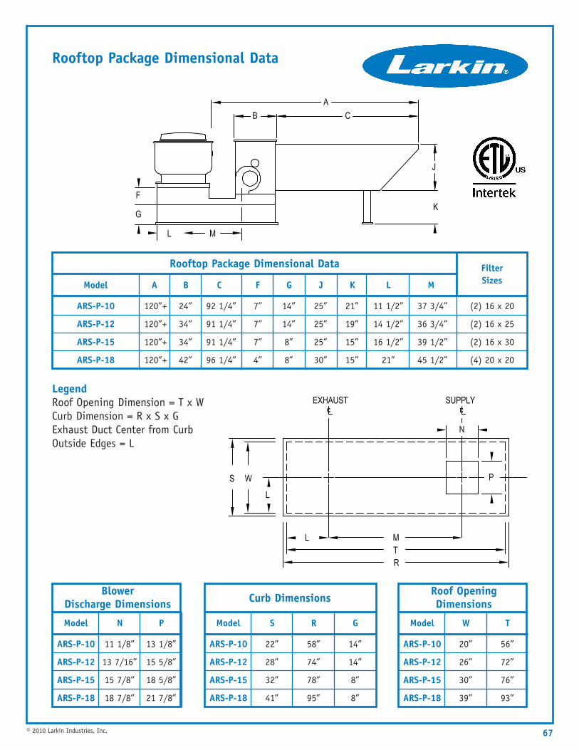
67© 2010 Larkin Industries, Inc.
Filter Sizes
(2) 16 x 20
(2) 16 x 25
(2) 16 x 30
(4) 20 x 20
120”+
120”+
120”+
120”+
A
24”
34”
34”
42”
B
92 1/4”
91 1/4”
91 1/4”
96 1/4”
C
7”
7”
7”
4”
14”
14”
8”
8”
F G
25”
25”
25”
30”
21”
19”
15”
15”
J
11 1/2”
14 1/2”
16 1/2”
21”
37 3/4”
36 3/4”
39 1/2”
45 1/2”
K L M
Rooftop Package Dimensional Data
Model
ARS-P-10
ARS-P-12
ARS-P-15
ARS-P-18
22”
28”
32”
41”
S
58”
74”
78”
95”
R
14”
14”
8”
8”
G
Curb Dimensions
Model
ARS-P-10
ARS-P-12
ARS-P-15
ARS-P-18
11 1/8”
13 7/16”
15 7/8”
18 7/8”
N
13 1/8”
15 5/8”
18 5/8”
21 7/8”
P
Blower Discharge Dimensions
Model
ARS-P-10
ARS-P-12
ARS-P-15
ARS-P-18
20”
26”
30”
39”
W
56”
72”
76”
93”
T
Roof OpeningDimensions
Rooftop Package Dimensional Data
LegendRoof Opening Dimension = T x WCurb Dimension = R x S x GExhaust Duct Center from CurbOutside Edges = L
Model
ARS-P-10
ARS-P-12
ARS-P-15
ARS-P-18
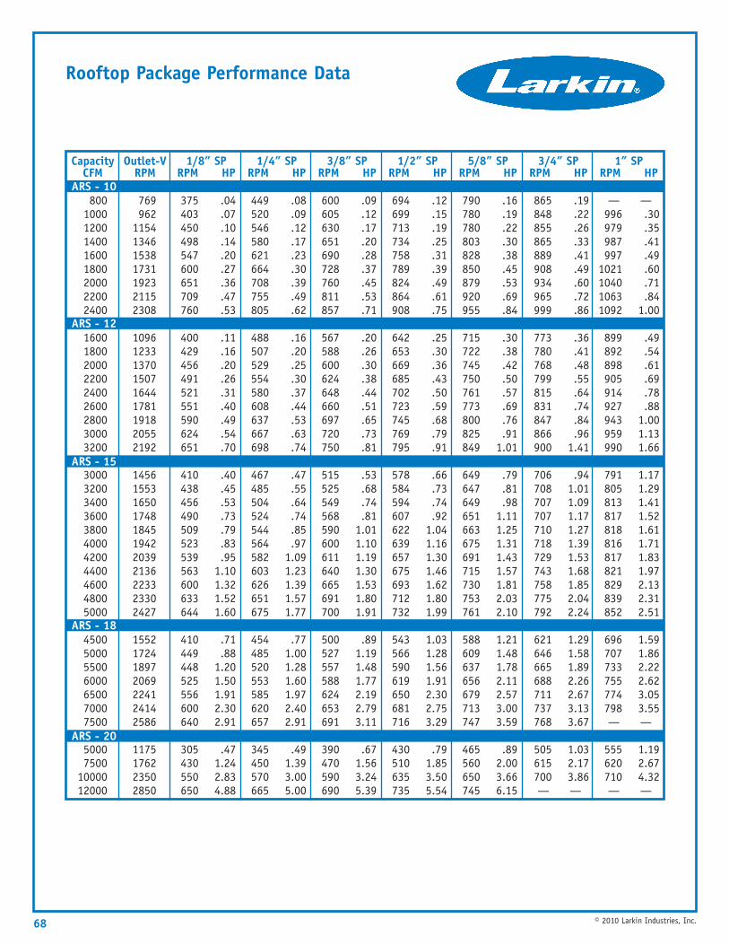
68 © 2010 Larkin Industries, Inc.
Rooftop Package Performance Data
CapacityCFM
80010001200140016001800200022002400
160018002000220024002600280030003200
30003200340036003800400042004400460048005000
4500500055006000650070007500
50007500
1000012000
Outlet-VRPM
1/8” SPRPM HP
769962
1154134615381731192321152308
109612331370150716441781191820552192
14561553165017481845194220392136223323302427
1552172418972069224124142586
1175176223502850
.04
.07
.10
.14
.20
.27
.36
.47
.53
.11
.16
.20
.26
.31
.40
.49
.54
.70
.40
.45
.53
.73
.79
.83
.951.101.321.521.60
.71
.881.201.501.912.302.91
.471.242.834.88
375403450498547600651709760
400429456491521551590624651
410438456490509523539563600633644
410449448525556600640
305430550650
.08
.09
.12
.17
.23
.30
.39
.49
.62
.16
.20
.25
.30
.37
.44
.53
.63
.74
.47
.55
.64
.74
.85
.971.091.231.391.571.77
.771.001.281.601.972.402.91
.491.393.005.00
449520546580621664708755805
488507529554580608637667698
467485504524544564582603626651675
454485520553585620657
345450570665
.09
.12
.17
.20
.28
.37
.45
.53
.71
.20
.26
.30
.38
.44
.51
.65
.73
.81
.53
.68
.74
.811.011.101.191.301.531.801.91
.891.191.481.772.192.793.11
.671.563.245.39
600605630651690728760811857
567588600624648660697720750
515525549568590600611640665691700
500527557588624653691
390470590690
.12
.15
.19
.25
.31
.39
.49
.61
.75
.25
.30
.36
.43
.50
.59
.68
.79
.91
.66
.73
.74
.921.041.161.301.461.621.801.99
1.031.281.561.912.302.753.29
.791.853.505.54
694699713734758789824864908
642653669685702723745769795
578584594607622639657675693712732
543566590619650681716
430510635735
.16
.19
.22
.30
.38
.45
.53
.69
.84
.30
.38
.42
.50
.57
.69
.76
.911.01
.79
.81
.981.111.251.311.431.571.812.032.10
1.211.481.782.112.573.003.59
.892.003.666.15
790780780803828850879920955
715722745750761773800825849
649647649651663675691715730753761
588609637656679713747
465560650745
.19
.22
.26
.33
.41
.49
.60
.72
.86
.36
.41
.48
.55
.64
.74
.84
.961.41
.941.011.091.171.271.391.531.681.852.042.24
1.291.581.892.262.673.133.67
1.032.173.86—
865848855865889908934965999
773780768799815831847866900
706708707707710718729743758775792
621646665688711737768
505615700—
—.30.35.41.49.60.71.84
1.00
.49
.54
.61
.69
.78
.881.001.131.66
1.171.291.411.521.611.711.831.972.132.312.51
1.591.862.222.623.053.55—
1.192.674.32—
—996979987997
1021104010631092
899892898905914927943959990
791805813817818816817821829839852
696707733755774798—
555620710—
1/4” SPRPM HP
3/8” SPRPM HP
1/2” SPRPM HP
5/8” SPRPM HP
3/4” SPRPM HP
1” SPRPM HP
ARS - 10
ARS - 12
ARS - 15
ARS - 18
ARS - 20
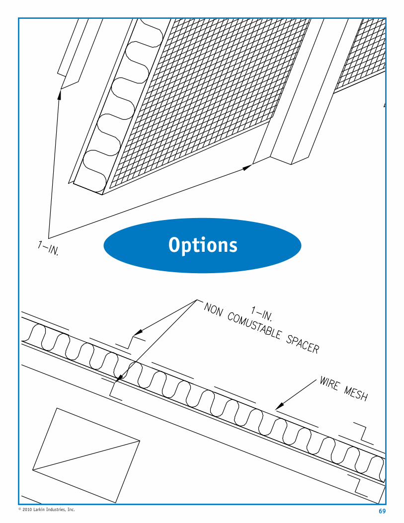
69© 2010 Larkin Industries, Inc.
Options
Standard Hood Features and Available Options
70 © 2010 Larkin Industries, Inc.
Standard Hood Features
Available Options
The following catalog pages are an overview of our Standard Hood options. They include descriptions, and illustrations ofthe options offered by Larkin Industries, Inc.
All Larkin hoods have been tested to Underwriters Laboratories 710 Standard and are listed for use with and withoutfire damper in exhaust collars by ETL (a nationally recognized testing laboratory of the United States). All Larkin hoodsmeet the requirements of NFPA 96, NFPA 70, IMC & NSF.
• 18 and 20-gauge 304 or 430 stainless steel or 18-gauge aluminized steel.• 12-gauge hanger brackets.• Duct collars shipped mounted or loose.• U.L classified baffle-type aluminum filter(s).• Removable grease trough and cup.• Complete packing for shipment.• ETL, NSF and built in accordance with NFPA 96 labels.• UL listed incandescent lights.
• Description of Options . . . . . . . . . . . . . . . . . . . . . . . pg 71• Pre-wired Controls . . . . . . . . . . . . . . . . . . . . . . . . . . pg 72• Auto Fan Controls . . . . . . . . . . . . . . . . . . . . . . . . . . . pg 74• Ansul Fire Suppression . . . . . . . . . . . . . . . . . . . . . . . . pg 76• Grease Filters . . . . . . . . . . . . . . . . . . . . . . . . . . . . . . pg 77• Recessed Fluorescent Lights . . . . . . . . . . . . . . . . . . . . pg 80• NFPA 96 Duct Work . . . . . . . . . . . . . . . . . . . . . . . . . pg 81• Fan Curbs . . . . . . . . . . . . . . . . . . . . . . . . . . . . . . . . pg 85• ETL Exhaust Duct Fire Damper . . . . . . . . . . . . . . . . . . pg 86• Back to Back / End to End Hood Installation . . . . . . . . pg 87• Enclosure Panels . . . . . . . . . . . . . . . . . . . . . . . . . . . . pg 89• End Panels . . . . . . . . . . . . . . . . . . . . . . . . . . . . . . . . pg 90• Fire Cabinets and Duct Shroud . . . . . . . . . . . . . . . . . . pg 91• Stand Offs . . . . . . . . . . . . . . . . . . . . . . . . . . . . . . . . pg 92• Wall Splash Panels . . . . . . . . . . . . . . . . . . . . . . . . . . pg 93• Split Plenums / Single Leaf Supply Dampers . . . . . . . . pg 94• Back Return Plenum . . . . . . . . . . . . . . . . . . . . . . . . . pg 95• Front Perforated Supply Plenum . . . . . . . . . . . . . . . . . pg 96
71© 2010 Larkin Industries, Inc.
Description of Options
Volume Damper Used to balance make-up air. Damper isconstructed of 18 gauge galvanized steel and is a singleleaf damper with locking quadrant handle. Shipped looseand field mounted over supply collar.
End Panel Used to maximize hood performance andeliminate cross drafts in kitchen. End panels have 1”flange for attaching to wall and exposed edges arehemmed for safety.
Duct Shroud: For use on back shelf type hoods to coverexhaust duct work from top of hood to ceiling. Standardmaterial is 20 gauge 430 stainless steel.
1,2, 3 or 4 Switch Panels Wall or hood mounted switchesare used to operate hood lights, exhaust and/or supplyfans. Switches are 20 amps, red pilot lighted, single anddouble pole. For complete description of electricaloptions see electrical packages on page 72.
Registers Standard registers are single deflection, frontvertical bars without opposed blade damper. Registers areavailable double deflection (front vertical bars, backhorizontal bars and opposed blade damper) standard alu-minum finish only.
Back Return Plenums A make-up air plenum is mounteddirectly to the wall extending from the wall 6” and downthe wall, terminating below the cooking equipment. Thekitchen hood is then mounted in front of the back returnplenum. The back-return plenum also acts as a stand-off.
Double Wall Construction Consists of two layers of steelon ends and fronts; required on some models.
Lights Recessed fluorescent lights and 12”x12” recessedIncandescent lights are available. Standard lights areincandescent with tempered glass globes. Wire guards areavailable. Lights are NSF and UL listed.
Filters Filters are UL classified and NSF approved. Filtersare available in stainless steel, aluminum, epoxy coated,teflon coated, adjustable and non-adjustable, and highvelocity slot. Spark arrestors are available for solid fuelcooking equipment.
Low Ceiling Hoods Front of hood is shorter than the backto allow for low ceiling applications to give proper headroom under the hood. Some models have a minimumallowable short front.
Finish Back The back of a wall style hood is finished andused in island application.
Front Perforated Supply Plenum A make up air plenumis mounted to the front of the hood that will dischargemake up air down through a perforated panel.
Auto Fan Control Automatically energizes fans whencooking operations commence in compliance with IMC507.2.1.1.
Metal Types & Gauges Larkin Industries, Inc. will constructany hood to your metal and gauge specifications. Someoptions are 304 stainless steel, carbon steel, and16 gauge material. Standard metals and gauges arealuminized, & 430 stainless steel 18 & 20 gauge.
Insulated Fronts 1” fiberglass foil back insulation on thefront inside of make-up air plenum. Insulation may beneeded in colder climates to prevent front of kitchenhood from condensating.
Full Insulated Plenum 1” Fiberglass foil back insulationin the entire make-up air plenum.
Fire Cabinet Used to enclose fire suppression system onend of kitchen hood. It has a removable door for easyaccess, open top (to facilitate fire suppression systempiping), and mounting rails. Optional electrical packagecan be installed in the face of the cabinet (firesuppression system not included).
All Stainless Steel The "all stainless steel” optionspecifies that all parts which come in contact with greaseladen vapors will be made of stainless steel with theexception of filters. However, stainless steel filters areavailable as an option. There will be some parts, internaland on the outside top, that will be made of galvanizedor aluminized steel. If you desire to have as much of thehood stainless steel as possible, please contact your salesrepresentative at Larkin for special pricing.
Ceiling Skirts Encloses the area between the top of thehood and ceiling in high ceiling or retro fit installations.Standard skirts are type 430, 20 gauge stainless steel or18 gauge aluminized steel.
Wall Splash Covers the wall behind cooking equipmentunder kitchen hood (required by some health departments).Standard wall splash materials are type 430, 20 gaugestainless steel.
Stand Offs 3”, 4”, & 6” stand-offs insulated and non-insulated are used to give kitchen hoods desiredclearance to combustible materials. Consult NFPA 96 orlocal codes for required clearance in your area.
Split Plenums Kitchen Hood Models SCRF, & ACRF mayrequire split plenums with 2 make-up air collars to ensureproper make-up air distribution on a specific kitchenhood design.
Collars Exhaust collars are heavy gauge aluminized steel.2” tall with 3/4” welding flange. Supply collars are 3” talland 10” wide standard. Some models require a supplycollar with fire damper per NFPA 96. Both exhaust andsupply collars can be mounted or shipped loose.
ANSUL Fire Suppression Larkin Industries, Inc. providescomplete pre-piping of hood with nozzles, detectors withlinks installed, regulated release assembly, tank(s),agents, remote pull station, gas valve, final field hook upand certification of system. Tanks can be wall mountedin a stainless steel enclosure or in a factory suppliedstainless steel fire cabinet mounted to the end of the hood.
Other options available upon request Consult factory.
72 © 2010 Larkin Industries, Inc.
Pre-wired Electrical Packages
The Electrical Control Package
The electrical control panels are ETL Listed for most appli-cations. Three phase or single phase control panels areavailable in various sizes depending on the number offans controlled by the panel. Each panel is equipped withthe required number of switches. There are 3 pre-wirelocation options:
1 Pre-wire located In the hood’s fire cabinet with theswitches on the face of the fire cabinet.
2 Pre-wire located on top of the hood with switchesmounted on the face of the hood. (This is an optiononly if the top of the hood is accessible, thereby providingaccessibility to the pre-wire package on top of the hood).
3 Wall mount stainless steel box. (This option requiresfield wiring of the lights and micro switches. With thisoption, the switches must be mounted on the face of thestainless steel box.) Switch covers are stainless steel.To meet most code interlock requirements, a single redlight switch is used for supply/exhaust combination. For hood lights, a single pole, gray handle switch is used as required.
Single Phase Control
The Listed control panel for single phase application hasminimum dimensions of 10” x 10” x 4”. 1/2” and 3/4”knockouts are provided to facilitate field connections.The Interior of the NEMA Approved control panel maycontain the following:• Coded wiring with numbered terminal blocks.• Grounding bar.• Spare terminals controlled by the fire system micro switch.• Factory control wiring to shut down the supply fan and
exhaust fan continues running in fire conditions.• Wiring diagram.• Relays controlled by the fan switch that carry the fan
loads. The maximum horsepower for a 120V standardpackage is 1 1/2 HP; for 220V, maximum horse poweris 2 HP. All wiring is encased In flexible conduit orEMT. The panel is factory tested prior to shipment.
Field wiring of the package requires the electrician to:1 Pull the specified power inputs from the main power
source to the control package.2 Pull the fan wires to each fan from the control
pannel. Additional field wiring may be required fromthe fire system micro switches and to the hood lights,depending on the mounting options chosen for thepre-wire control package. The system is complete afterconnections are made per wiring diagram.
Three Phase Control Package
The ETL Listed control panel for three phase applicationshas minimum dimensions of 12” x 12” x 6”. 1/2” and 3/4”knockouts are provided to facilitate field connections.The interior of the NEMA Approved control panel maycontain the following:• Coded wiring with numbered terminal blocks.• Grounding bar.• Starters with overloads. The starters are controlled by
the fan switches.• Distribution blocks (which allow up to four (4) three
phase fans to be fed by one (1) three phase circuit).• Spare terminals controlled by the fire system micro switch.• Factory control wiring to shut down the supply fan and
exhaust fan continues running in fire conditions.• Wiring diagram. Wiring is encased in flexible conduit or
EMT. The panel is factory tested prior to shipment.
Field wiring of the package requires the electrician to:1 Pull the specified power Inputs from the main power
source to the distribution blocks for three phase power.2 Pull the specified power inputs for single phase power
for the light and control circuits to the control package.3 Pull from output terminal blocks to each fan from the
control panel. Additional field wiring may be requiredfrom the fire system micro switch and to the hoodlights, depending on the mounting option chosen forthe prewire control package. The system is completeafter connections are made per wiring diagram.
Auto Fan Control System
The Larkin auto fan control system is completelypre-wired including hood mounted controls, controllerpackage, starter or contactor package and hood mountedsensors. The auto fan control system will automaticallyenergize the fans as the temperature of the cookingequipment rises and cooking operations commence incompliance with international mechanical code 507.2.1.1.The auto fan control system has a hood mounted temper-ature adjustment dial factory pre-set at 80° f that willadjust to meet warmer or cooler kitchen environments.The auto fan control system also includes a “cool down”delay that allows the fans to operate for 30 minutesafter the set temperature has been achieved. This willprevent any unwanted on-off cycling of the fans while theequipment cools.
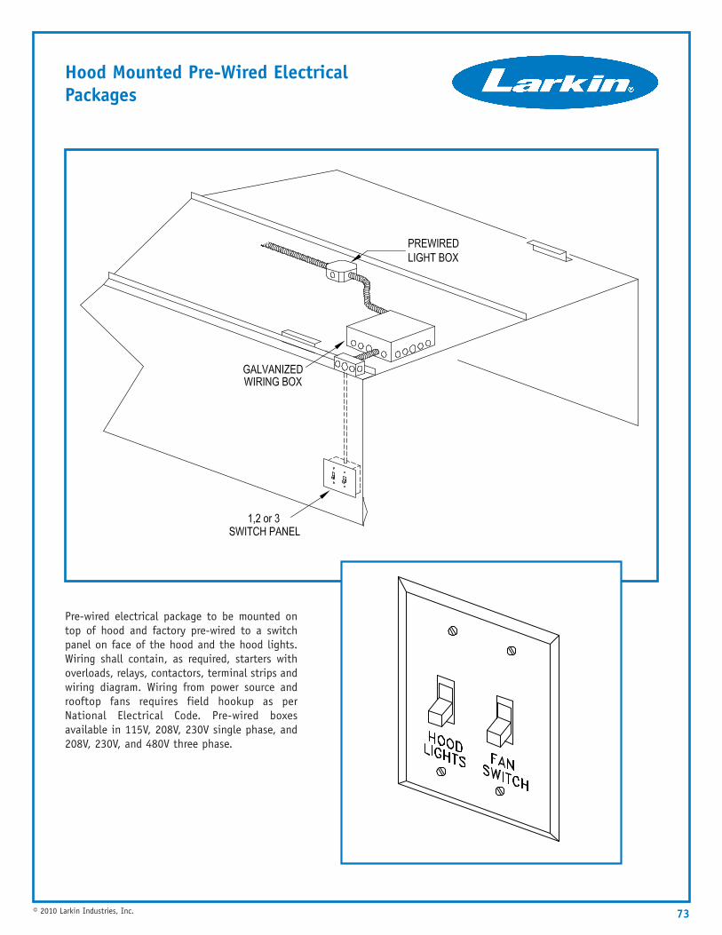
73© 2010 Larkin Industries, Inc.
Hood Mounted Pre-Wired ElectricalPackages
Pre-wired electrical package to be mounted ontop of hood and factory pre-wired to a switchpanel on face of the hood and the hood lights.Wiring shall contain, as required, starters withoverloads, relays, contactors, terminal strips andwiring diagram. Wiring from power source androoftop fans requires field hookup as perNational Electrical Code. Pre-wired boxesavailable in 115V, 208V, 230V single phase, and208V, 230V, and 480V three phase.
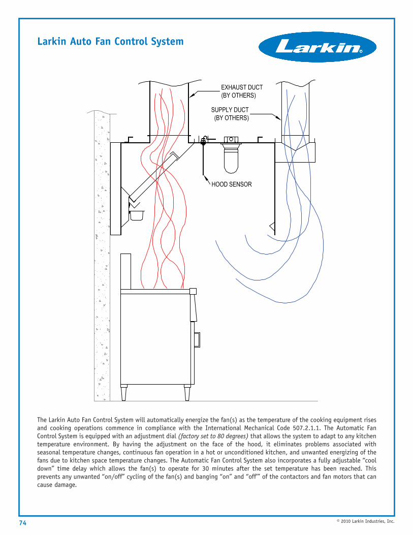
74 © 2010 Larkin Industries, Inc.
Larkin Auto Fan Control System
The Larkin Auto Fan Control System will automatically energize the fan(s) as the temperature of the cooking equipment risesand cooking operations commence in compliance with the International Mechanical Code 507.2.1.1. The Automatic FanControl System is equipped with an adjustment dial (factory set to 80 degrees) that allows the system to adapt to any kitchentemperature environment. By having the adjustment on the face of the hood, it eliminates problems associated withseasonal temperature changes, continuous fan operation in a hot or unconditioned kitchen, and unwanted energizing of thefans due to kitchen space temperature changes. The Automatic Fan Control System also incorporates a fully adjustable “cooldown” time delay which allows the fan(s) to operate for 30 minutes after the set temperature has been reached. Thisprevents any unwanted “on/off” cycling of the fan(s) and banging “on” and “off’” of the contactors and fan motors that cancause damage.
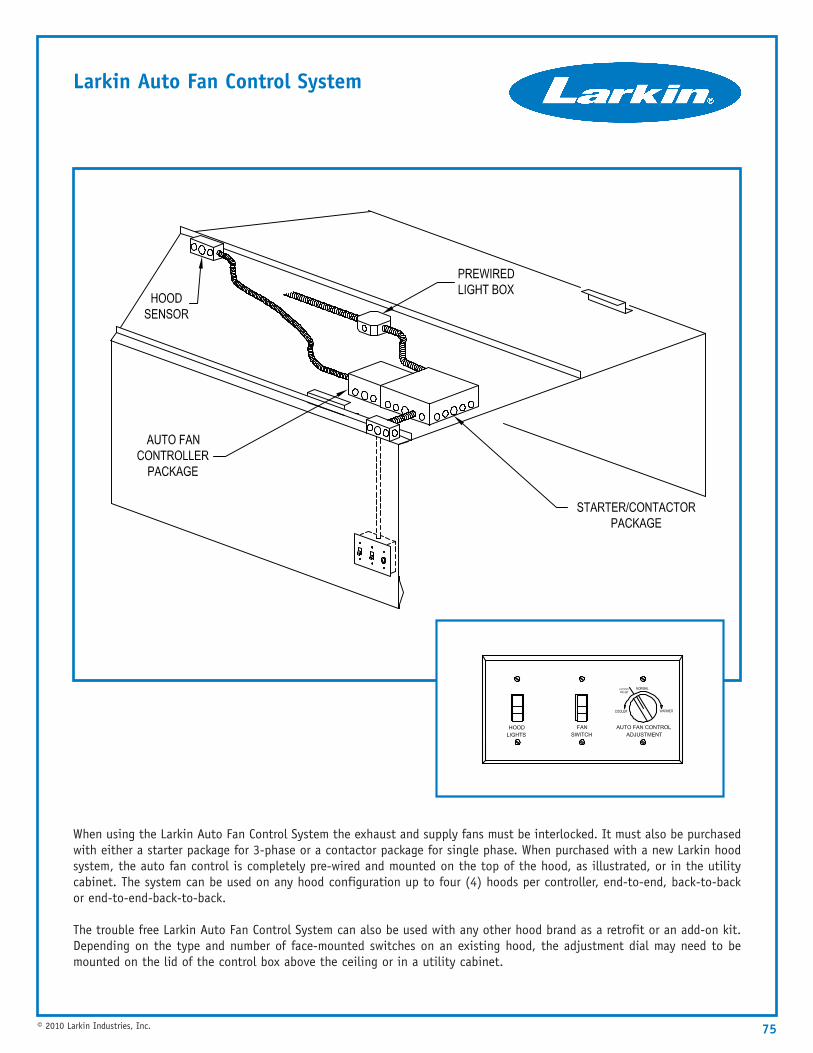
75© 2010 Larkin Industries, Inc.
Larkin Auto Fan Control System
When using the Larkin Auto Fan Control System the exhaust and supply fans must be interlocked. It must also be purchasedwith either a starter package for 3-phase or a contactor package for single phase. When purchased with a new Larkin hoodsystem, the auto fan control is completely pre-wired and mounted on the top of the hood, as illustrated, or in the utilitycabinet. The system can be used on any hood configuration up to four (4) hoods per controller, end-to-end, back-to-backor end-to-end-back-to-back.
The trouble free Larkin Auto Fan Control System can also be used with any other hood brand as a retrofit or an add-on kit.Depending on the type and number of face-mounted switches on an existing hood, the adjustment dial may need to bemounted on the lid of the control box above the ceiling or in a utility cabinet.
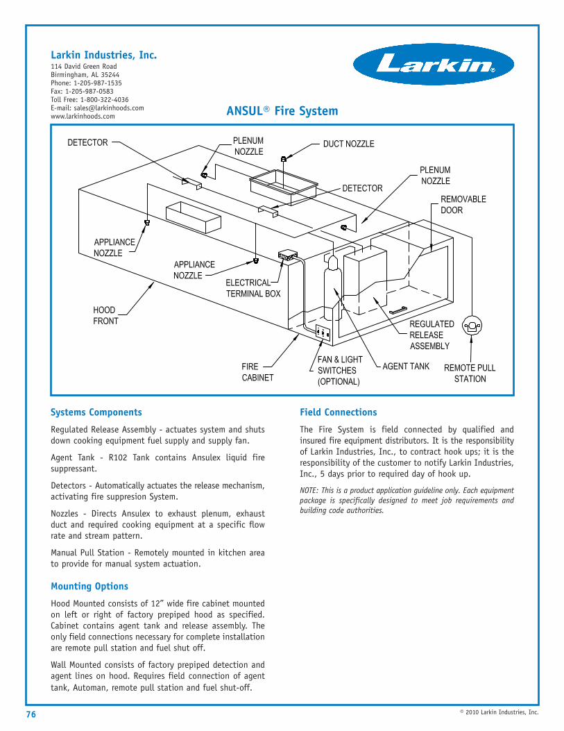
76 © 2010 Larkin Industries, Inc.
Systems Components
Regulated Release Assembly - actuates system and shutsdown cooking equipment fuel supply and supply fan.
Agent Tank - R102 Tank contains Ansulex liquid firesuppressant.
Detectors - Automatically actuates the release mechanism,activating fire suppresion System.
Nozzles - Directs Ansulex to exhaust plenum, exhaustduct and required cooking equipment at a specific flowrate and stream pattern.
Manual Pull Station - Remotely mounted in kitchen areato provide for manual system actuation.
Mounting Options
Hood Mounted consists of 12” wide fire cabinet mountedon left or right of factory prepiped hood as specified.Cabinet contains agent tank and release assembly. Theonly field connections necessary for complete installationare remote pull station and fuel shut off.
Wall Mounted consists of factory prepiped detection andagent lines on hood. Requires field connection of agenttank, Automan, remote pull station and fuel shut-off.
Field Connections
The Fire System is field connected by qualified andinsured fire equipment distributors. It is the responsibilityof Larkin Industries, Inc., to contract hook ups; it is theresponsibility of the customer to notify Larkin Industries,Inc., 5 days prior to required day of hook up.
NOTE: This is a product application guideline only. Each equipmentpackage is specifically designed to meet job requirements andbuilding code authorities.
ANSUL® Fire System
Larkin Industries, Inc.114 David Green RoadBirmingham, AL 35244Phone: 1-205-987-1535Fax: 1-205-987-0583Toll Free: 1-800-322-4036E-mail: [email protected]
77© 2010 Larkin Industries, Inc.
Grease Filters
Operation
Grease laden air is drawn into the filter by the exhaustfans. As the air starts through the baffle system, itundergoes a series of compressions, expansions andpressure changes. The heavy grease is deposited safelyand quickly on the baffles while the grease-free airpasses through the filter and up the exhaust duct. Thebaffle’s smooth surface enables the collected grease torun off into collection troughs without dripping on food,utensils or burner surfaces. The baffle filter method ofseparating grease and air has achieved superior levels ofefficiency and safety.
Self -Balancing
Baffle filters are designed to provide a self-balancing airflow throughout the entire length of a hood. The bafflefilters unique design assures good capture through theentire hood length, with 25% to 50% less volume ofexhaust air.
Construction
Baffle filters are constructed of heavy duty stainlesssteel, aluminum, teflon coated, & epoxy resin-coatedassuring durability which will provide years of trouble-freeoperation. Baffle filters are Underwriter Laboratoriesclassified & NSF approved.
Installation
Baffle filters are available in all standard commercialsizes and are installed in the same manner asconventional filters. Baffle filters may replace meshfilters in existing kitchens without the need for elaboratesystem revisions.
Maintenance
The construction allows the filter to be soaked, sprayedor placed in a dishwasher for simplified cleaning, withoutconcern for rusting or damaging the filters.
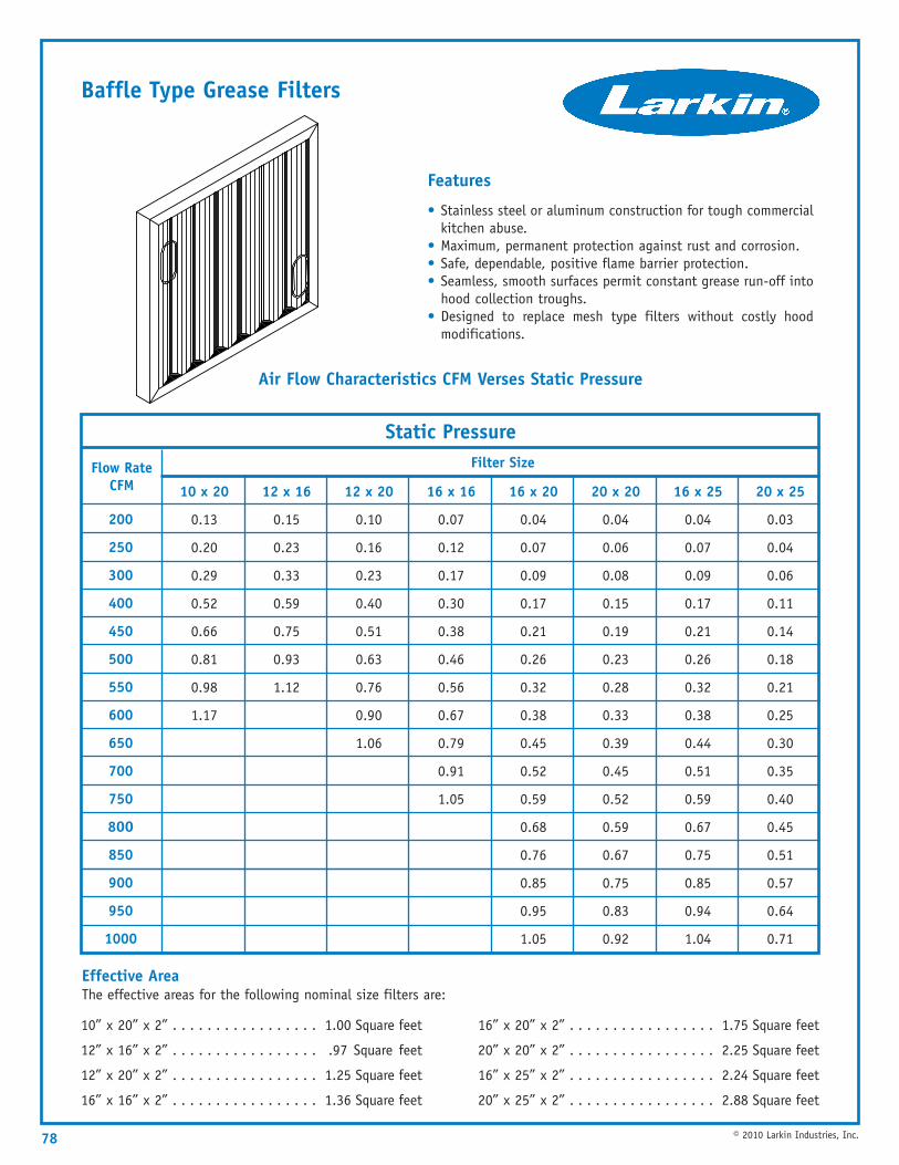
Features
• Stainless steel or aluminum construction for tough commercialkitchen abuse.
• Maximum, permanent protection against rust and corrosion.• Safe, dependable, positive flame barrier protection.• Seamless, smooth surfaces permit constant grease run-off into
hood collection troughs.• Designed to replace mesh type filters without costly hood
modifications.
10” x 20” x 2” . . . . . . . . . . . . . . . . . 1.00 Square feet
12” x 16” x 2” . . . . . . . . . . . . . . . . . .97 Square feet
12” x 20” x 2” . . . . . . . . . . . . . . . . . 1.25 Square feet
16” x 16” x 2” . . . . . . . . . . . . . . . . . 1.36 Square feet
16” x 20” x 2” . . . . . . . . . . . . . . . . . 1.75 Square feet
20” x 20” x 2” . . . . . . . . . . . . . . . . . 2.25 Square feet
16” x 25” x 2” . . . . . . . . . . . . . . . . . 2.24 Square feet
20” x 25” x 2” . . . . . . . . . . . . . . . . . 2.88 Square feet
78 © 2010 Larkin Industries, Inc.
Filter Size
10 x 20
0.13
0.20
0.29
0.52
0.66
0.81
0.98
1.17
12 x 16
0.15
0.23
0.33
0.59
0.75
0.93
1.12
12 x 20
0.10
0.16
0.23
0.40
0.51
0.63
0.76
0.90
1.06
16 x 16
0.07
0.12
0.17
0.30
0.38
0.46
0.56
0.67
0.79
0.91
1.05
16 x 20
0.04
0.07
0.09
0.17
0.21
0.26
0.32
0.38
0.45
0.52
0.59
0.68
0.76
0.85
0.95
1.05
20 x 20
0.04
0.06
0.08
0.15
0.19
0.23
0.28
0.33
0.39
0.45
0.52
0.59
0.67
0.75
0.83
0.92
16 x 25
0.04
0.07
0.09
0.17
0.21
0.26
0.32
0.38
0.44
0.51
0.59
0.67
0.75
0.85
0.94
1.04
20 x 25
0.03
0.04
0.06
0.11
0.14
0.18
0.21
0.25
0.30
0.35
0.40
0.45
0.51
0.57
0.64
0.71
Flow Rate CFM
200
250
300
400
450
500
550
600
650
700
750
8OO
850
900
950
1000
Static Pressure
Effective AreaThe effective areas for the following nominal size filters are:
Baffle Type Grease Filters
Air Flow Characteristics CFM Verses Static Pressure
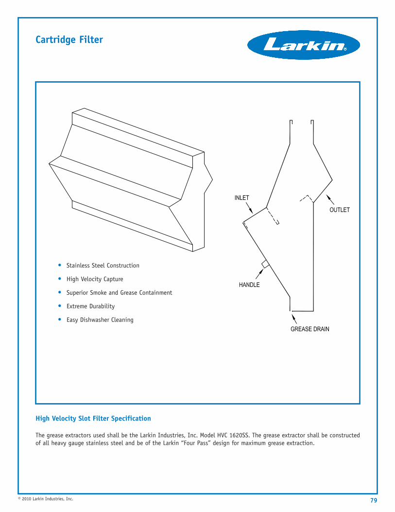
79© 2010 Larkin Industries, Inc.
Cartridge Filter
High Velocity Slot Filter Specification
The grease extractors used shall be the Larkin Industries, Inc. Model HVC 1620SS. The grease extractor shall be constructedof all heavy gauge stainless steel and be of the Larkin “Four Pass” design for maximum grease extraction.
• Stainless Steel Construction
• High Velocity Capture
• Superior Smoke and Grease Containment
• Extreme Durability
• Easy Dishwasher Cleaning
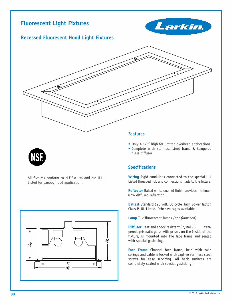
80 © 2010 Larkin Industries, Inc.
Fluorescent Light Fixtures
Recessed Fluoresent Hood Light Fixtures
Features
• Only 4 1/2” high for limited overhead applications• Complete with stainless steel frame & tempered
glass diffuser
Specifications
Wiring Rigid conduit is connected to the special U.LListed threaded hub and connections made to the fixture.
Reflector Baked white enamel finish provides minimum87% diffused reflection.
Ballast Standard 120 volt, 60 cycle, high power factor,Class P, UL Listed. Other voltages available.
Lamp T12 fluorescent lamps (not furnished).
Diffuser Heat and shock resistant Crystal 73 tem-pered, prismatic glass with prisms on the Inside of thefixture, is mounted into the face frame and sealedwith special gasketing.
Face Frame Channel face frame, held with twinsprings and cable is locked with captive stainless steelscrews for easy servicing. All back surfaces arecompletely sealed with special gasketing.
All fixtures conform to N.F.P.A. 96 and are U.L.Listed for canopy hood application.
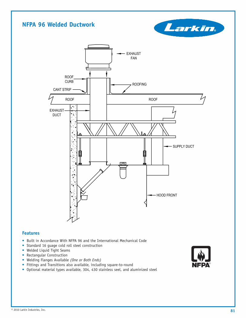
NFPA 96 Welded Ductwork
Features• Built in Accordance With NFPA 96 and the International Mechanical Code• Standard 16 guage cold roll steel construction• Welded Liquid Tight Seams• Rectangular Construction• Welding Flanges Available (One or Both Ends)• Fittings and Transitions also available, including square-to-round• Optional material types available, 304, 430 stainless seel, and aluminized steel
81© 2010 Larkin Industries, Inc.
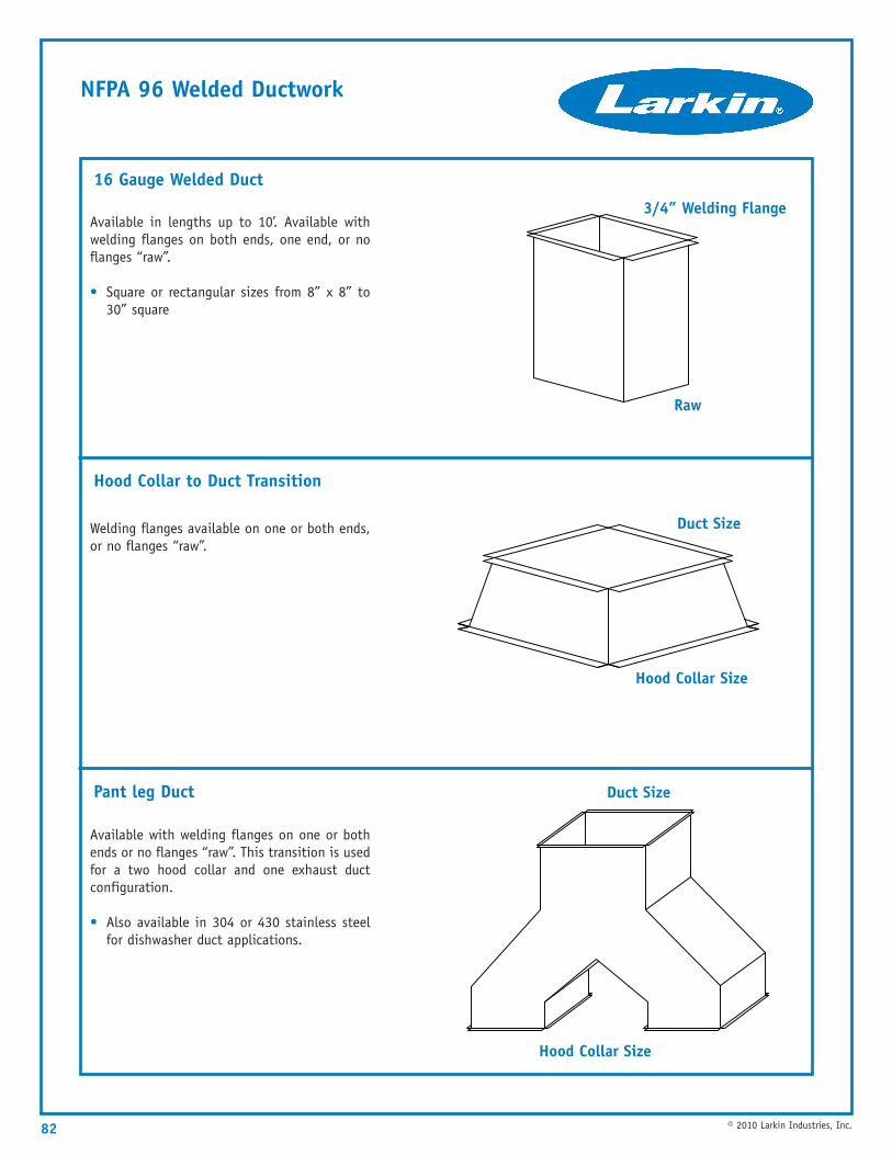
NFPA 96 Welded Ductwork
82 © 2010 Larkin Industries, Inc.
Available with welding flanges on one or bothends or no flanges “raw”. This transition is usedfor a two hood collar and one exhaust ductconfiguration.
• Also available in 304 or 430 stainless steelfor dishwasher duct applications.
Welding flanges available on one or both ends,or no flanges “raw”.
Available in lengths up to 10’. Available withwelding flanges on both ends, one end, or noflanges “raw”.
• Square or rectangular sizes from 8” x 8” to30” square
16 Gauge Welded Duct
Hood Collar to Duct Transition
Pant leg Duct
Hood Collar Size
Duct Size
Hood Collar Size
Duct Size
Raw
3/4” Welding Flange
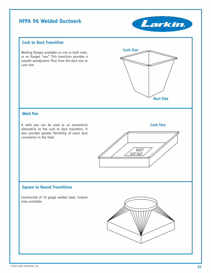
NFPA 96 Welded Ductwork
83© 2010 Larkin Industries, Inc.
Constructed of 16 gauge welded steel. Customsizes available.
A weld pan can be used as an economicalalternative to the curb to duct transition, italso provides greater flexibility of exact ductconnection in the field.
Welding flanges available on one or both ends,or no flanges “raw”. This transition provides asmooth aerodynamic flow from the duct size tocurb size.
Curb to Duct Transition
Weld Pan
Square to Round Transitions
Curb Size
Duct Size
Curb Size
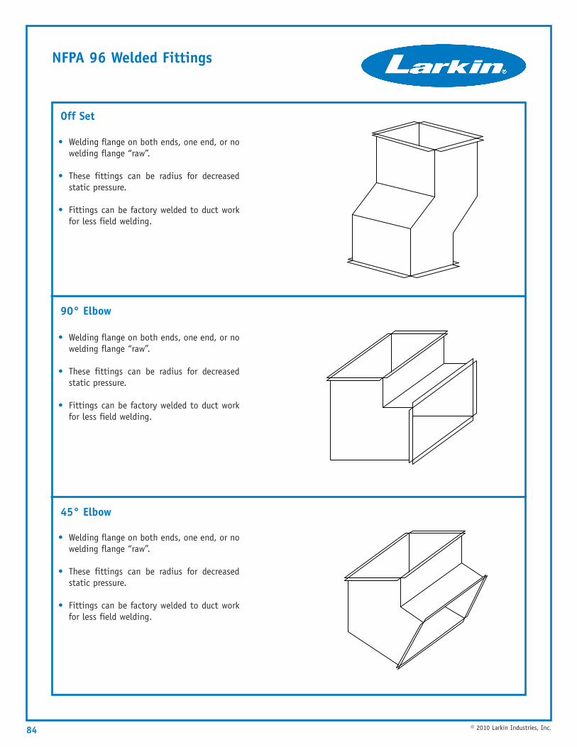
NFPA 96 Welded Fittings
84 © 2010 Larkin Industries, Inc.
• Welding flange on both ends, one end, or nowelding flange “raw”.
• These fittings can be radius for decreasedstatic pressure.
• Fittings can be factory welded to duct workfor less field welding.
• Welding flange on both ends, one end, or nowelding flange “raw”.
• These fittings can be radius for decreasedstatic pressure.
• Fittings can be factory welded to duct workfor less field welding.
• Welding flange on both ends, one end, or nowelding flange “raw”.
• These fittings can be radius for decreasedstatic pressure.
• Fittings can be factory welded to duct workfor less field welding.
Off Set
90° Elbow
45° Elbow
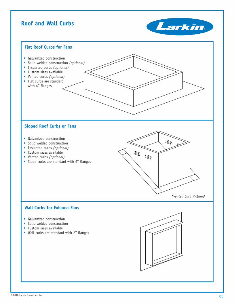
Roof and Wall Curbs
85© 2010 Larkin Industries, Inc.
• Galvanized construction• Solid welded construction• Custom sizes available• Wall curbs are standard with 2” flanges
• Galvanized construction• Solid welded construction• Insulated curbs (optional)• Custom sizes available• Vented curbs (optional)• Slope curbs are standard with 6” flanges
Sloped Roof Curbs or Fans
Wall Curbs for Exhaust Fans
• Galvanized construction• Solid welded construction (optional)• Insulated curbs (optional)• Custom sizes available• Vented curbs (optional)• Flat curbs are standard
with 4” flanges
Flat Roof Curbs for Fans
*Vented Curb Pictured

86 © 2010 Larkin Industries, Inc.
ETL Listed Fire Damper In Exhaust
Open
Closed
Note: No longer accepted in most jurisdictions.
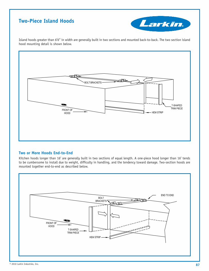
87© 2010 Larkin Industries, Inc.
Two-Piece Island Hoods
Island hoods greater than 6’6” in width are generally built in two sections and mounted back-to-back. The two section islandhood mounting detail is shown below.
Two or More Hoods End-to-EndKitchen hoods longer than 16’ are generally built in two sections of equal length. A one-piece hood longer than 16’ tendsto be cumbersome to install due to weight, difficulty in handling, and the tendency toward damage. Two-section hoods aremounted together end-to-end as described below.
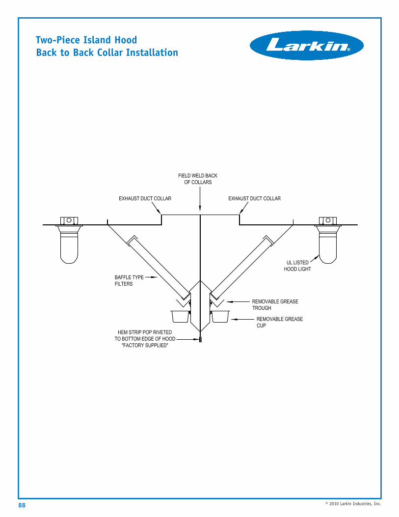
88 © 2010 Larkin Industries, Inc.
Two-Piece Island HoodBack to Back Collar Installation
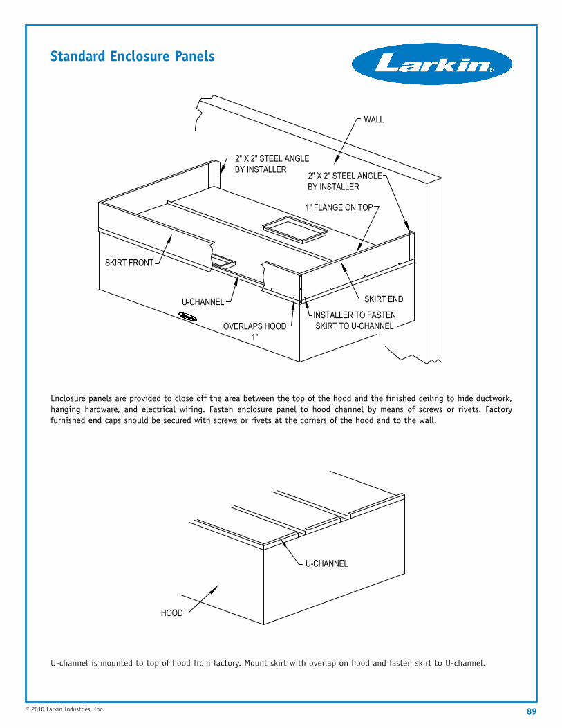
89© 2010 Larkin Industries, Inc.
Standard Enclosure Panels
U-channel is mounted to top of hood from factory. Mount skirt with overlap on hood and fasten skirt to U-channel.
Enclosure panels are provided to close off the area between the top of the hood and the finished ceiling to hide ductwork,hanging hardware, and electrical wiring. Fasten enclosure panel to hood channel by means of screws or rivets. Factoryfurnished end caps should be secured with screws or rivets at the corners of the hood and to the wall.
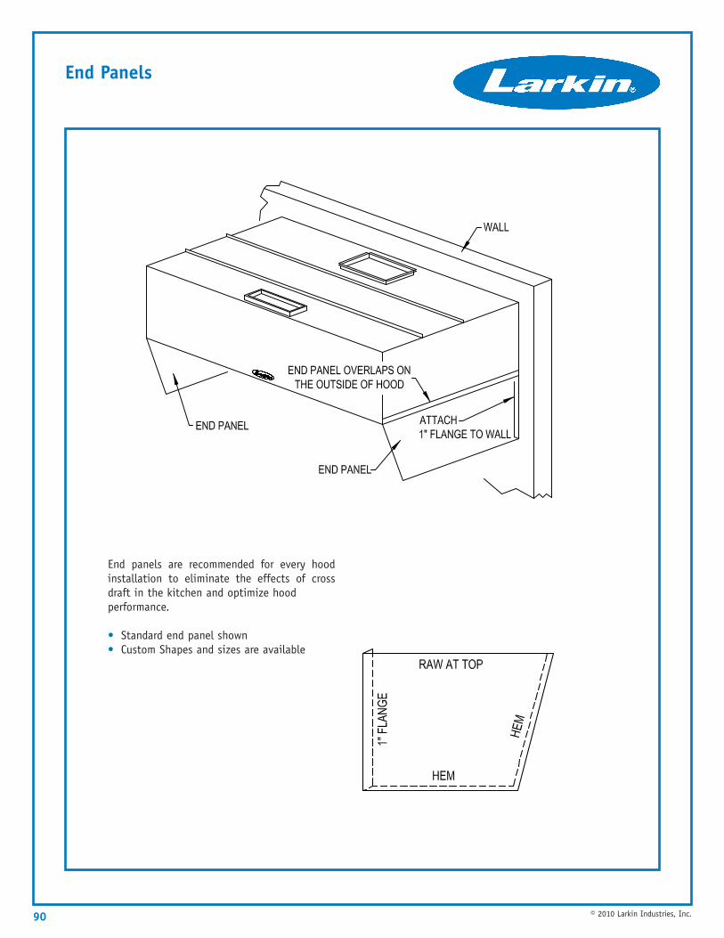
90 © 2010 Larkin Industries, Inc.
End Panels
End panels are recommended for every hoodinstallation to eliminate the effects of crossdraft in the kitchen and optimize hood performance.
• Standard end panel shown• Custom Shapes and sizes are available
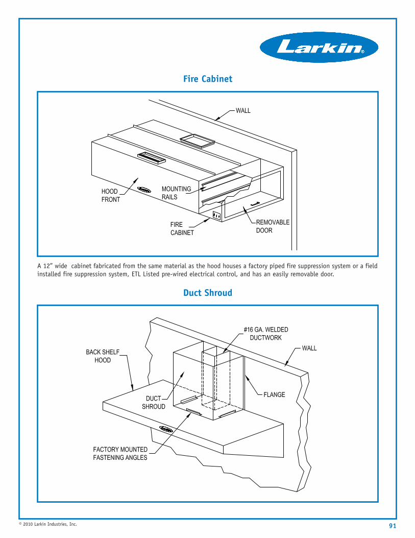
91© 2010 Larkin Industries, Inc.
A 12” wide cabinet fabricated from the same material as the hood houses a factory piped fire suppression system or a fieldinstalled fire suppression system, ETL Listed pre-wired electrical control, and has an easily removable door.
Fire Cabinet
Duct Shroud
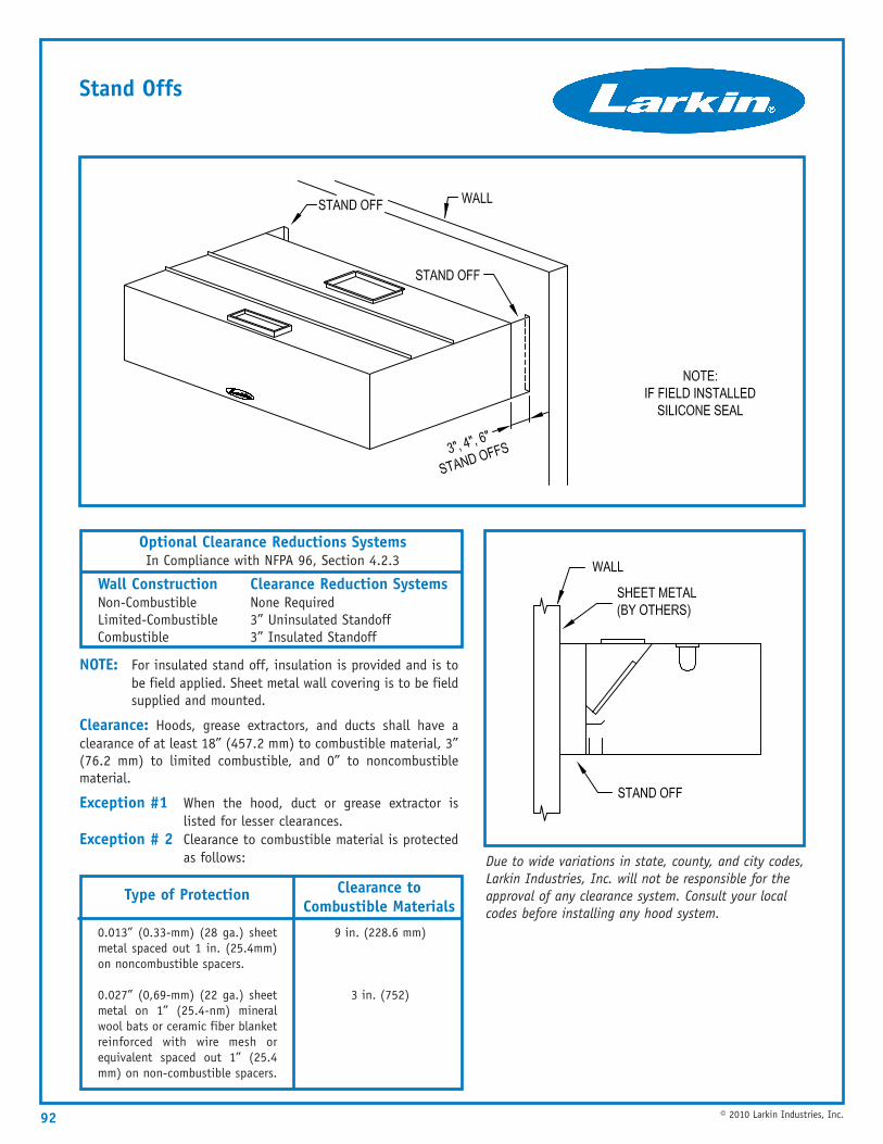
92 © 2010 Larkin Industries, Inc.
Stand Offs
Optional Clearance Reductions SystemsIn Compliance with NFPA 96, Section 4.2.3
Wall ConstructionNon-CombustibleLimited-CombustibleCombustible
Clearance Reduction SystemsNone Required3” Uninsulated Standoff3” Insulated Standoff
Clearance to Combustible Materials
Type of Protection
0.013” (0.33-mm) (28 ga.) sheetmetal spaced out 1 in. (25.4mm)on noncombustible spacers.
0.027” (0,69-mm) (22 ga.) sheetmetal on 1” (25.4-nm) mineralwool bats or ceramic fiber blanketreinforced with wire mesh orequivalent spaced out 1” (25.4mm) on non-combustible spacers.
9 in. (228.6 mm)
3 in. (752)
NOTE: For insulated stand off, insulation is provided and is tobe field applied. Sheet metal wall covering is to be fieldsupplied and mounted.
Clearance: Hoods, grease extractors, and ducts shall have aclearance of at least 18” (457.2 mm) to combustible material, 3”(76.2 mm) to limited combustible, and 0” to noncombustiblematerial.
Exception #1 When the hood, duct or grease extractor islisted for lesser clearances.
Exception # 2 Clearance to combustible material is protectedas follows: Due to wide variations in state, county, and city codes,
Larkin Industries, Inc. will not be responsible for theapproval of any clearance system. Consult your localcodes before installing any hood system.
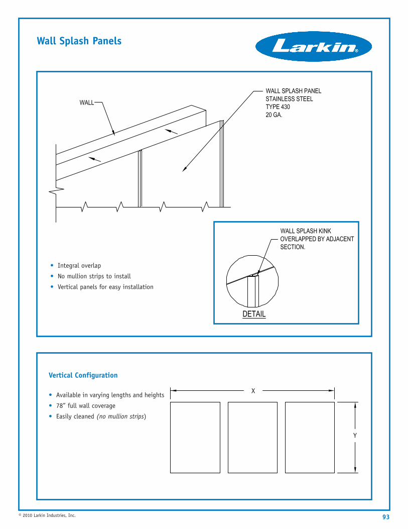
93© 2010 Larkin Industries, Inc.
Wall Splash Panels
Vertical Configuration
• Available in varying lengths and heights
• 78” full wall coverage
• Easily cleaned (no mullion strips)
• Integral overlap
• No mullion strips to install
• Vertical panels for easy installation
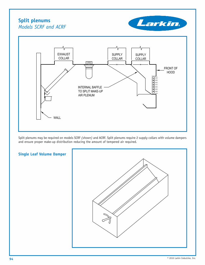
94 © 2010 Larkin Industries, Inc.
Split plenumsModels SCRF and ACRF
Split plenums may be required on models SCRF (shown) and ACRF. Split plenums require 2 supply collars with volume dampersand ensure proper make-up distribution reducing the amount of tempered air required.
Single Leaf Volume Damper
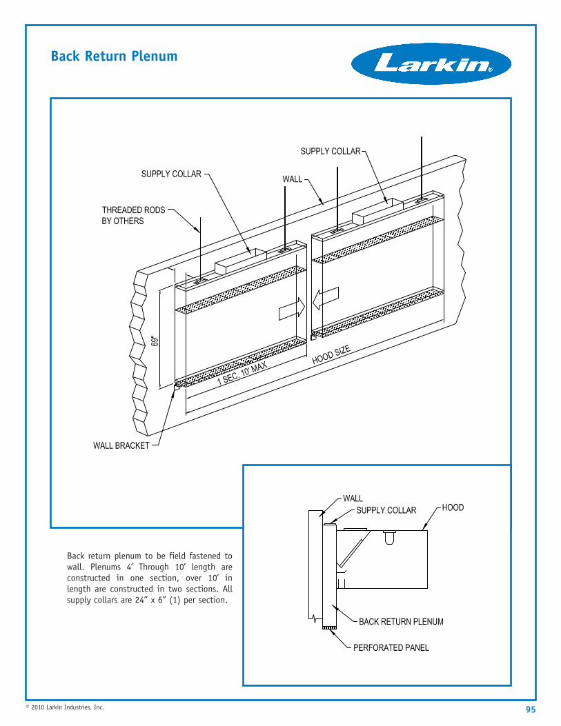
95© 2010 Larkin Industries, Inc.
Back Return Plenum
Back return plenum to be field fastened towall. Plenums 4’ Through 10’ length areconstructed in one section, over 10’ inlength are constructed in two sections. Allsupply collars are 24” x 6” (1) per section.
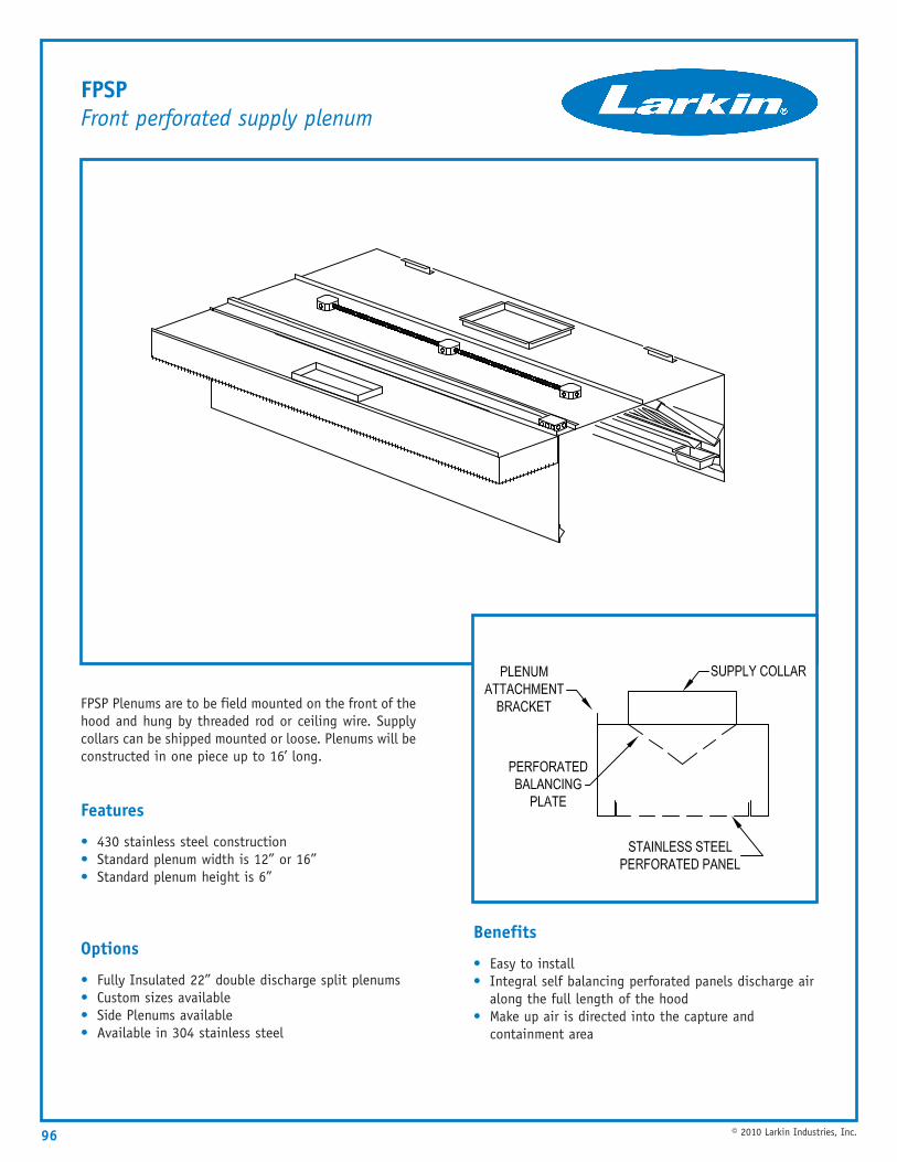
96 © 2010 Larkin Industries, Inc.
FPSPFront perforated supply plenum
FPSP Plenums are to be field mounted on the front of thehood and hung by threaded rod or ceiling wire. Supplycollars can be shipped mounted or loose. Plenums will beconstructed in one piece up to 16’ long.
Features
• 430 stainless steel construction• Standard plenum width is 12” or 16”• Standard plenum height is 6”
Options
• Fully Insulated 22” double discharge split plenums• Custom sizes available• Side Plenums available• Available in 304 stainless steel
Benefits
• Easy to install• Integral self balancing perforated panels discharge air
along the full length of the hood• Make up air is directed into the capture and
containment area
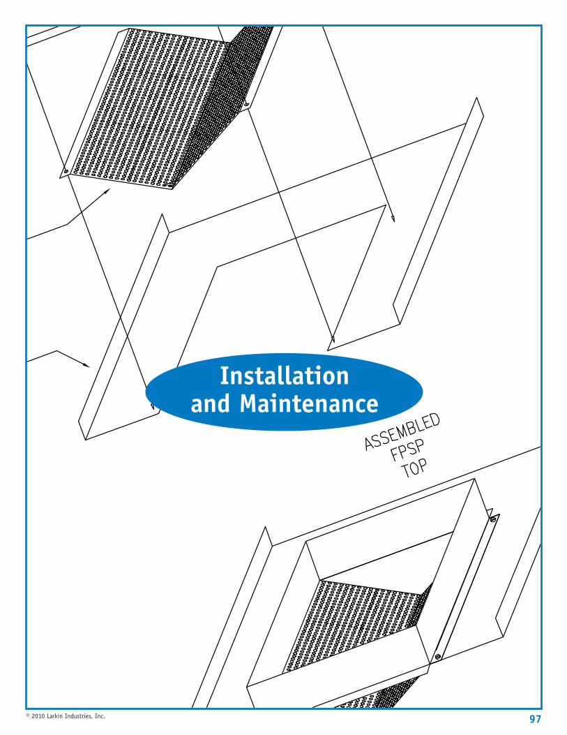
97© 2010 Larkin Industries, Inc.
Installationand Maintenance
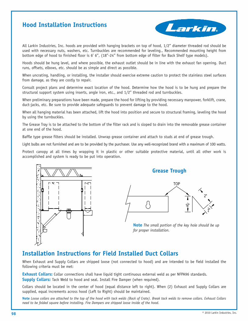
98 © 2010 Larkin Industries, Inc.
All Larkin Industries, Inc. hoods are provided with hanging brackets on top of hood, 1/2” diameter threaded rod should beused with necessary nuts, washers, etc. Turnbuckles are recommended for leveling., Recommended mounting height frombottom edge of hood to finished floor is 6’ 6”, (18”-24” from bottom edge of filter for Back Shelf type models).
Hoods should be hung level, and where possible, the exhaust outlet should be in line with the exhaust fan opening. Ductruns, offsets, elbows, etc. should be as simple and direct as possible.
When uncrating, handling, or installing, the installer should exercise extreme caution to protect the stainless steel surfacesfrom damage, as they are costly to repair.
Consult project plans and determine exact location of the hood. Determine how the hood is to be hung and prepare thestructural support system using inserts, angle iron, etc., and 1/2” threaded rod and turnbuckles.
When preliminary preparations have been made, prepare the hood for lifting by providing necessary manpower, forklift, crane,duct-jacks, etc. Be sure to provide adequate safeguards to prevent damage to the hood.
When all hanging material has been attached, lift the hood into position and secure to structural framing, leveling the hoodby using the turnbuckles.
The Grease Tray is to be attached to the bottom of the filter rack and is sloped to drain into the removable grease containerat one end of the hood.
Baffle type grease filters should be installed. Unwrap grease container and attach to studs at end of grease trough.
Light bulbs are not furnished and are to be provided by the purchaser. Use any well-recognized brand with a maximum of 100 watts.
Protect canopy at all times by wrapping it in plastic or other suitable protective material, until all other work isaccomplished and system is ready to be put into operation.
Hood Installation Instructions
Note The small portion of the key hole should be upfor proper installation.
Installation Instructions for Field Installed Duct CollarsWhen Exhaust and Supply Collars are shipped loose (not connected to hood) and are intended to be field installed thefollowing criteria must be met:
Exhaust Collars: Collar connections shall have liquid tight continuous external weld as per NFPA96 standards.Supply Collars: Tack Weld to hood and seal. Install Fire Damper (when required).
Collars should be located in the center of hood (equal distance left to right). When (2) Exhaust and Supply Collars aresupplied, equal increments across hood (Left to Right) should be maintained.
Note Loose collars are attached to the top of the hood with tack welds (Back of Crate). Break tack welds to remove collars. Exhaust Collarsneed to be folded square before installing. Fire Dampers are shipped loose inside of the hood.
Grease Trough
99© 2010 Larkin Industries, Inc.
Ductwork NFPA 96 requires that the exhaust duct be installed using 16 gauge carbon steel or 18 gauge stainless steel and alljoints and seams be welded liquid tight. In any event, conformance to local codes must be adhered to unless variance is obtained.
NFPA 96 further requires that a minimum of 500 FPM velocity be maintained in the exhaust duct. There is no specifiedmaximum; however, velocity should not exceed 2200 FPM.
Make-up air ductwork should contain adequate filtering provisions somewhere in the system before it is introduced into thespace or into the hood. Consult a licensed mechanical contractor familiar with hood installations and code requirements.
Wiring Consult a Licensed Electrician to complete any wiring that is required.
Start-Up Determine that the installation is complete and in accordance with the project plans and specifications, that theduct system is complete, and that all electrical connections have been made.
Electrical systems should be installed with disconnecting means, proper fusing and proper grounding system to protectagainst hazardous shock.
By physical observation, check the supply and exhaust fans for proper operation by checking voltage, motor overload, noiselevel, amperage, rotation, etc. Verify that motors and bearings have proper lubrication and that the belts have propertension. Deflection in belt tension should not exceed 1/2”. Check that the air intake filters are in place and clean andthat the fire damper in the hood supply collar is open. If the airflow as measured is not in accordance with the projectspecifications, adjust the speeds of the respective fans as required and re-check.
After the system has been placed in operation and balancing of the system has been accomplished, a visual inspectionshould be made of the entire system. This inspection should include such things as unusual noises, excessive exhaust orsupply air and general operation of the system.
Always instruct the owner/operator in the proper operation and maintenance of the system.
MaintenanceHood Inspect the grease extractors daily for grease deposits. Inspect the grease container daily and empty. Wipe theinterior of the hood daily, if possible, to remove deposits or accumulations of grease. Clean the interior of the hood andclean the light fixtures.
Once each week, wash the grease extractors in a dishwasher or other container with a mild detergent in warm or hot water.NEVER USE HARSH OR ABRASIVE CLEANERS ON STAINLESS STEEL.
Note If a kitchen ventilation hood is cleaned with a pressure-washer or steam cleaner, the silicone sealant will be removed from the sealedseams. Also, standard daily cleaning, over time, will loosen the seal and the silicone will be removed from the sealed seams. The sealant maybe replaced, after a thorough cleaning and de-greasing, with a food grade, high temperature silicone.
Fans Check cleanliness of intake filters every two weeks for a one-month period to establish a cleaning schedule. To cleanfilters, flush filters with warm soapy water and recoat with a filter coat adhesive. Replace filters and lid. Check condition offan drive belts upon initial installation and again after a period of two weeks. Belts tend to stretch during the initial periodof operation and should be inspected monthly. Properly adjusted belt tension will allow approximately 1/2” deflection on eachside of the belt, midway between the pulley centers with slight finger pressure. Overly tightened belts will cause wear, motoroverloading, bearing wear and noise. Under tightened belts will cause belt wear, pulley wear and poor fan performance.
A monthly cleaning of exhaust wheel and interior of the fan housing is required. Oil and/or grease all motors and bearingevery six months, or as conditions dictate.
At least once a year, check motor and fan shafts. Clean and check tightness and alignment
One-Year WarrantyExcept for motors (see separate warranty on motors), Larkin Industries, Inc. warrants to its purchaser that each ventilator manufactured by Larkin shall befree from defects in material and workmanship for a period of one year from the date of shipment by Larkin to the original Purchaser, if the ventilator hasbeen subjected to normal use and service. If it appears within the warranty period that any such ventilator or material used therein does not meet thewarranties specified above, the Purchaser must notify the Company immediately. Failure to notify within a reasonable time, voids the warranty. The Companyagrees to remedy any such defect promptly by either repair or replacement, at the Company’s sole discretion of any alleged defective part (exclusive ofmotors covered separately herein). Cost of installation or removal of any failed unit or part thereof will be the sole responsibility of the Purchaser.
This warranty does not guarantee the proper design or installation of any ventilator nor is there any warranty concerning the ability of the ventilator toremove smoke, grease or heat. There is no warranty that the ventilator will be approved by, or meet, any local codes. This is a material warranty only. Ifthe equipment has been altered or repaired in any way, the Company shall have the right, in its sole discretion to void the warranty. If the equipment hasbeen improperly installed, subjected to misuse, been subjected to negligence, been subjected to accident, or been improperly maintained or lubricated,the Company shall have the right, in its sole discretion, to void the Warranty.
Note Replacement of silicone sealant is not covered by any warranty, expressed or implied, that is issued by Larkin Industries, Inc.
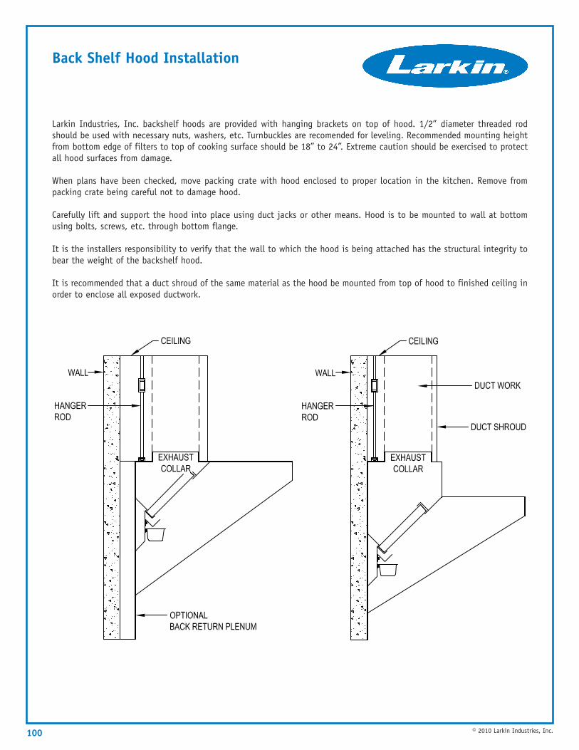
100 © 2010 Larkin Industries, Inc.
Larkin Industries, Inc. backshelf hoods are provided with hanging brackets on top of hood. 1/2” diameter threaded rodshould be used with necessary nuts, washers, etc. Turnbuckles are recomended for leveling. Recommended mounting heightfrom bottom edge of filters to top of cooking surface should be 18” to 24”. Extreme caution should be exercised to protectall hood surfaces from damage.
When plans have been checked, move packing crate with hood enclosed to proper location in the kitchen. Remove frompacking crate being careful not to damage hood.
Carefully lift and support the hood into place using duct jacks or other means. Hood is to be mounted to wall at bottomusing bolts, screws, etc. through bottom flange.
It is the installers responsibility to verify that the wall to which the hood is being attached has the structural integrity tobear the weight of the backshelf hood.
It is recommended that a duct shroud of the same material as the hood be mounted from top of hood to finished ceiling inorder to enclose all exposed ductwork.
Back Shelf Hood Installation
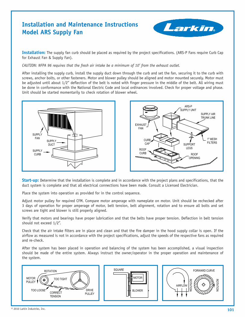
101© 2010 Larkin Industries, Inc.
Installation and Maintenance InstructionsModel ARS Supply Fan
Start-up: Determine that the installation is complete and in accordance with the project plans and specifications, that theduct system is complete and that all electrical connections have been made. Consult a Licensed Electrician.
Place the system into operation as provided for in the control sequence.
Adjust motor pulley for required CFM. Compare motor amperage with nameplate on motor. Unit should be rechecked after3 days of operation for proper amperage of motor, belt tension, belt alignment, rotation and to ensure all bolts and setscrews are tight and blower is still properly aligned.
Verify that motors and bearings have proper lubrication and that the belts have proper tension. Deflection in belt tensionshould not exceed 1/2”.
Check that the air intake filters are in place and clean and that the fire damper in the hood supply collar is open. If theairflow as measured is not in accordance with the project specifications, adjust the speeds of the respective fans as requiredand re-check.
After the system has been placed in operation and balancing of the system has been accomplished, a visual inspectionshould be made of the entire system. Always instruct the owner/operator in the proper operation and maintenance ofthe system.
Installation: The supply fan curb should be placed as required by the project specifications. (ARS-P Fans require Curb Capfor Exhaust Fan & Supply Fan).
CAUTION: NFPA 96 requires that the fresh air intake be a minimum of 10’ from the exhaust outlet.
After installing the supply curb, install the supply duct down through the curb and set the fan, securing it to the curb withscrews, anchor bolts, or other fasteners. Motor and blower pulley should be aligned and motor mounted securely. Motor mustbe adjusted until about 1/2” deflection of the belt is noted with finger pressure in the middle of the belt. All wiring mustbe done in conformance with the National Electric Code and local ordinances involved. Check for proper voltage and phase.Unit should be started momentarily to check rotation of blower wheel.
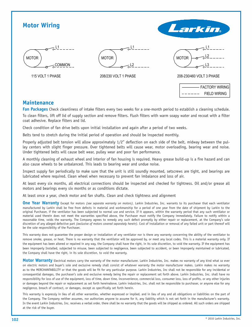
102 © 2010 Larkin Industries, Inc.
MaintenanceFan Packages Check cleanliness of intake filters every two weeks for a one-month period to establish a cleaning schedule.
To clean filters, lift off lid of supply section and remove filters. Flush filters with warm soapy water and recoat with a filtercoat adhesive. Replace filters and lid.
Check condition of fan drive belts upon initial installation and again after a period of two weeks.
Belts tend to stretch during the initial period of operation and should be inspected monthly.
Properly adjusted belt tension will allow approximately 1/2” deflection on each side of the belt, midway between the pul-ley centers with slight finger pressure. Over tightened belts will cause wear, motor overloading, bearing wear and noise.Under tightened belts will cause belt wear, pulley wear and poor fan performance.
A monthly cleaning of exhaust wheel and interior of fan housing is required. Heavy grease build-up is a fire hazard and canalso cause wheels to be unbalanced. This leads to bearing wear and undue noise.
Inspect supply fan periodically to make sure that the unit is still soundly mounted, setscrews are tight, and bearings arelubricated where required. Clean wheel when necessary to prevent fan imbalance and loss of air.
At least every six months, all electrical connections should be inspected and checked for tightness. Oil and/or grease allmotors and bearings every six months or as conditions dictate.
At least once a year, check motor and fan shafts. Clean and check tightness and alignment
One Year Warranty Except for motors (see separate warranty on motors), Larkin Industries, Inc. warrants to its purchaser that each ventilatormanufactured by Larkin shall be free from defects in material and workmanship for a period of one year from the date of shipment by Larkin to theoriginal Purchaser, if the ventilator has been subjected to normal use and service. If it appears, within the warranty period that any such ventilator ormaterial used therein does not meet the warranties specified above, the Purchaser must notify the Company immediately. Failure to notify within areasonable time, voids the warranty. The Company agrees to remedy any such defect promptly by either repair or replacement, at the Company’s solediscretion of any alleged defective part (exclusive of motors covered separately herein). Cost of installation or removal of any failed unit or part thereof willbe the sole responsibility of the Purchaser.
This warranty does not guarantee the proper design or installation of any ventilator nor is there any warranty concerning the ability of the ventilator toremove smoke, grease, or heat. There is no warranty that the ventilator will be approved by, or meet any local codes. This is a material warranty only. Ifthe equipment has been altered or repaired in any way, the Company shall have the right, in its sole discretion, to void the warranty. If the equipment hasbeen improperly Installed, subjected to misuse, been subjected to negligence, been subjected to accident, or been improperly maintained or lubricated,the Company shall have the right, in its sole discretion, to void the warranty.
Motor Warranty Electrical motors carry the warranty of the motor manufacturer. Larkin Industries, Inc. makes no warranty of any kind what so everon electric motors and buyer’s sole and exclusive remedy shall consist of whatever warranty the motor manufacturer makes. Larkin makes no warrantyas to the MERCHANTABILITY or that the goods will be fit for any particular purpose. Larkin Industries, Inc shall not be responsible for any incidental orconsequential damages, the purchaser’s sole and exclusive remedy being the repair or replacement set forth above. Larkin Industries, Inc. shall have noresponsibility for loss of use of the equipment, loss of time, down time, inconvenience, commercial loss, consumer loss, loss of profits, or any other injuriesor damages beyond the repair or replacement as set forth hereinabove. Larkin industries, Inc. shall not be responsible to purchaser, or anyone else for anynegligence, breach of contract, or damages, except as specifically set forth herein.
This warranty is expressly in lieu of all other warranties, whether expressed or implied, and in lieu of any and all obligations or liabilities on the part ofthe Company. The Company neither assumes, nor authorizes anyone to assume for it, any liability which is not set forth in the manufacturer’s warranty.In the event Larkin Industries, Inc. receives a verbal order, there shall be no warranty that the goods will be shipped as ordered. All such orders are shippedat the risk of the buyer.
Motor Wiring
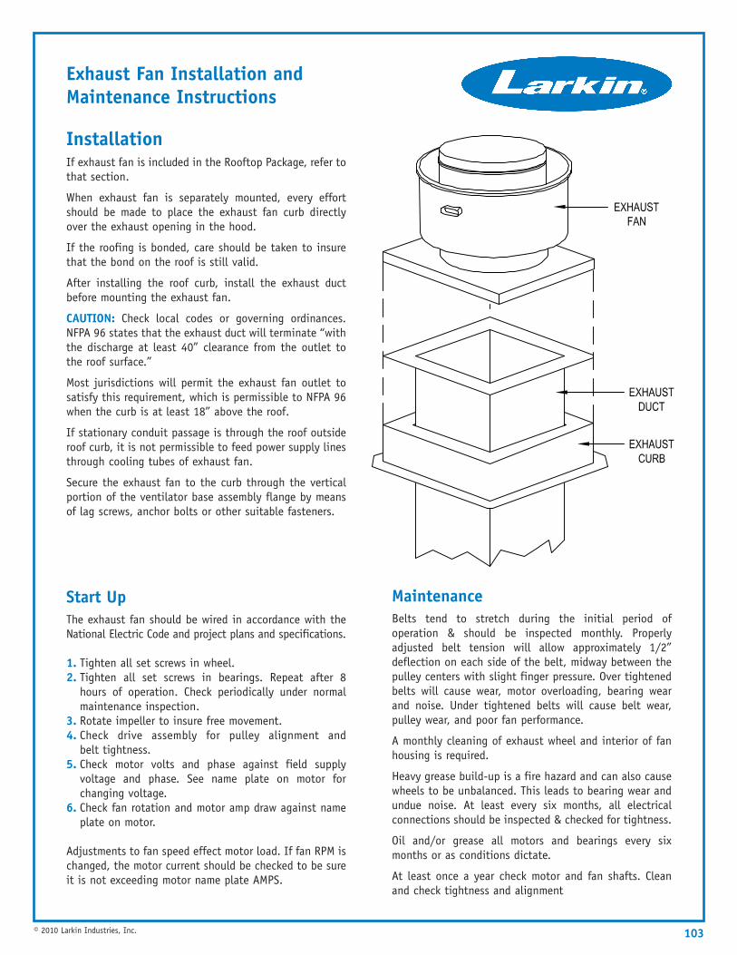
103© 2010 Larkin Industries, Inc.
InstallationIf exhaust fan is included in the Rooftop Package, refer tothat section.
When exhaust fan is separately mounted, every effortshould be made to place the exhaust fan curb directlyover the exhaust opening in the hood.
If the roofing is bonded, care should be taken to insurethat the bond on the roof is still valid.
After installing the roof curb, install the exhaust ductbefore mounting the exhaust fan.
CAUTION: Check local codes or governing ordinances.NFPA 96 states that the exhaust duct will terminate “withthe discharge at least 40” clearance from the outlet tothe roof surface.”
Most jurisdictions will permit the exhaust fan outlet tosatisfy this requirement, which is permissible to NFPA 96when the curb is at least 18” above the roof.
If stationary conduit passage is through the roof outsideroof curb, it is not permissible to feed power supply linesthrough cooling tubes of exhaust fan.
Secure the exhaust fan to the curb through the verticalportion of the ventilator base assembly flange by meansof lag screws, anchor bolts or other suitable fasteners.
Start UpThe exhaust fan should be wired in accordance with theNational Electric Code and project plans and specifications.
1. Tighten all set screws in wheel.2. Tighten all set screws in bearings. Repeat after 8
hours of operation. Check periodically under normalmaintenance inspection.
3. Rotate impeller to insure free movement.4. Check drive assembly for pulley alignment and
belt tightness.5. Check motor volts and phase against field supply
voltage and phase. See name plate on motor forchanging voltage.
6. Check fan rotation and motor amp draw against nameplate on motor.
Adjustments to fan speed effect motor load. If fan RPM ischanged, the motor current should be checked to be sureit is not exceeding motor name plate AMPS.
MaintenanceBelts tend to stretch during the initial period ofoperation & should be inspected monthly. Properlyadjusted belt tension will allow approximately 1/2”deflection on each side of the belt, midway between thepulley centers with slight finger pressure. Over tightenedbelts will cause wear, motor overloading, bearing wearand noise. Under tightened belts will cause belt wear,pulley wear, and poor fan performance.
A monthly cleaning of exhaust wheel and interior of fanhousing is required.
Heavy grease build-up is a fire hazard and can also causewheels to be unbalanced. This leads to bearing wear andundue noise. At least every six months, all electricalconnections should be inspected & checked for tightness.
Oil and/or grease all motors and bearings every sixmonths or as conditions dictate.
At least once a year check motor and fan shafts. Cleanand check tightness and alignment
Exhaust Fan Installation and Maintenance Instructions
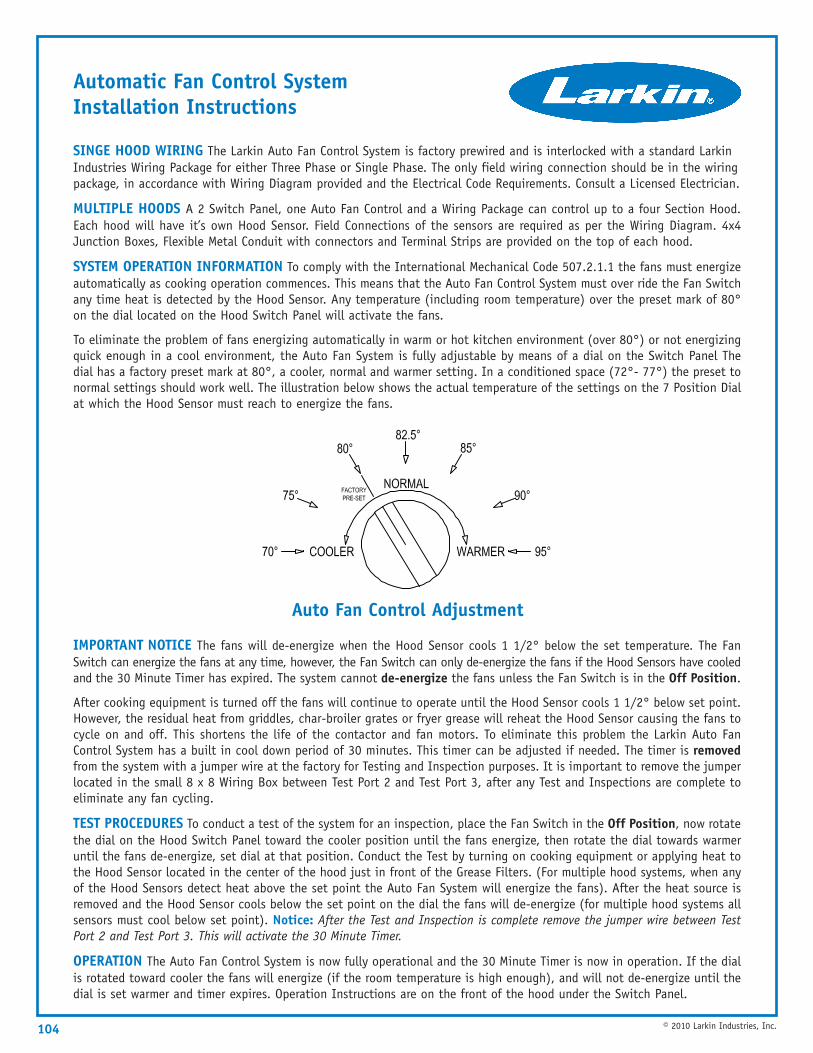
104 © 2010 Larkin Industries, Inc.
SINGE HOOD WIRING The Larkin Auto Fan Control System is factory prewired and is interlocked with a standard LarkinIndustries Wiring Package for either Three Phase or Single Phase. The only field wiring connection should be in the wiringpackage, in accordance with Wiring Diagram provided and the Electrical Code Requirements. Consult a Licensed Electrician.
MULTIPLE HOODS A 2 Switch Panel, one Auto Fan Control and a Wiring Package can control up to a four Section Hood.Each hood will have it’s own Hood Sensor. Field Connections of the sensors are required as per the Wiring Diagram. 4x4Junction Boxes, Flexible Metal Conduit with connectors and Terminal Strips are provided on the top of each hood.
SYSTEM OPERATION INFORMATION To comply with the International Mechanical Code 507.2.1.1 the fans must energizeautomatically as cooking operation commences. This means that the Auto Fan Control System must over ride the Fan Switchany time heat is detected by the Hood Sensor. Any temperature (including room temperature) over the preset mark of 80°on the dial located on the Hood Switch Panel will activate the fans.
To eliminate the problem of fans energizing automatically in warm or hot kitchen environment (over 80°) or not energizingquick enough in a cool environment, the Auto Fan System is fully adjustable by means of a dial on the Switch Panel Thedial has a factory preset mark at 80°, a cooler, normal and warmer setting. In a conditioned space (72°- 77°) the preset tonormal settings should work well. The illustration below shows the actual temperature of the settings on the 7 Position Dialat which the Hood Sensor must reach to energize the fans.
Automatic Fan Control System Installation Instructions
Auto Fan Control Adjustment
IMPORTANT NOTICE The fans will de-energize when the Hood Sensor cools 1 1/2° below the set temperature. The FanSwitch can energize the fans at any time, however, the Fan Switch can only de-energize the fans if the Hood Sensors have cooledand the 30 Minute Timer has expired. The system cannot de-energize the fans unless the Fan Switch is in the Off Position.
After cooking equipment is turned off the fans will continue to operate until the Hood Sensor cools 1 1/2° below set point.However, the residual heat from griddles, char-broiler grates or fryer grease will reheat the Hood Sensor causing the fans tocycle on and off. This shortens the life of the contactor and fan motors. To eliminate this problem the Larkin Auto FanControl System has a built in cool down period of 30 minutes. This timer can be adjusted if needed. The timer is removedfrom the system with a jumper wire at the factory for Testing and Inspection purposes. It is important to remove the jumperlocated in the small 8 x 8 Wiring Box between Test Port 2 and Test Port 3, after any Test and Inspections are complete toeliminate any fan cycling.
TEST PROCEDURES To conduct a test of the system for an inspection, place the Fan Switch in the Off Position, now rotatethe dial on the Hood Switch Panel toward the cooler position until the fans energize, then rotate the dial towards warmeruntil the fans de-energize, set dial at that position. Conduct the Test by turning on cooking equipment or applying heat tothe Hood Sensor located in the center of the hood just in front of the Grease Filters. (For multiple hood systems, when anyof the Hood Sensors detect heat above the set point the Auto Fan System will energize the fans). After the heat source isremoved and the Hood Sensor cools below the set point on the dial the fans will de-energize (for multiple hood systems allsensors must cool below set point). Notice: After the Test and Inspection is complete remove the jumper wire between TestPort 2 and Test Port 3. This will activate the 30 Minute Timer.
OPERATION The Auto Fan Control System is now fully operational and the 30 Minute Timer is now in operation. If the dialis rotated toward cooler the fans will energize (if the room temperature is high enough), and will not de-energize until thedial is set warmer and timer expires. Operation Instructions are on the front of the hood under the Switch Panel.

Phone 1-205-987-1535Fax 1-205-987-0583Toll Free 1-800-322-4036E-mail [email protected]
www.LarkinHoods.comLarkin Industries, Inc. Product Catalog (July 2010)
Larkin Industries, Inc.114 David Green RoadBirmingham, Alabama 35244
PRSRT STDU.S. POSTAGE
PAIDPELHAM, AL
PERMIT NO. 252