laser-driven dielectric-structure accelerators† · laser-driven dielectric-structure...
TRANSCRIPT

Laser-Driven Dielectric-Structure Accelerators*
Eric R. Colby†
Accelerator Research Department B SLAC
* http://www-project.slac.stanford.edu/e163/DielectricAccelTalk.pdf† [email protected]
Work supported by Department of Energy contracts DE-AC03-76SF00515 (SLAC) and DE-FG03-97ER41043-II (LEAP).

July 21, 2003 2
The LEAP & E163 Collaborators
C. D. Barnes, E. R. Colby, B. M. Cowan, M. Javanmard, R. J. Noble, D. T. Palmer, C. M. Sears, R. H. Siemann, J. E. Spencer, D. R. Walz
Stanford Linear Accelerator Center
R. L. Byer, T. Plettner, J. A. WisdomStanford University
T. I. Smith, R. L. SwentHansen Experimental Physics Laboratory
Y.-C. HuangNational Tsing Hua University, Taiwan
L. SchächterThe Technion
Israeli Institute of Technology, Haifa

July 21, 2003 3
Why is laser-driven acceleration in “vacuum” worth pursuing?
What are the most promising laser acceleration methods?
What R&D is needed to make a working laser accelerator?
“Vacuum”:- No plasmas, background gases; only solid objects- Low-field ao= eE/2�mc « 1
�Laser-Driven Linear Collider Concept
Crossed-Gaussian AcceleratorPhotonic Band Gap Accelerator
STELLALaser Electron Accelerator Project (LEAP)E163, SPRC, and follow-on programs at ORION
General Roadmap
Physical and Technical Issues

July 21, 2003 4
Requirements for FutureHigh Energy Linear Colliders
Near Term:• Center-of-mass energy 0.5-1.0 TeV• Luminosity >1034 cm-2 s-1
Long Term:• >3 TeV and readily extendable• Luminosity >1035 cm-2 s-1 and increasing with �2
Compactness, power efficiency, reliability, affordability
Linear optical-wavelength acceleration requires:
Sub-femtosecond electron bunches � sub-fs radiation pulses
Very small emittance beams � radiation sources are truly point-like

July 21, 2003 5
High Power Density � High Field Strength
*28.5 GeV, 1e10 ppp, ���x ���x ���� (20� for SPPS) beam
**350 MeV, 1e10 ppp, 1� x 1� x 1 mm beam
Source Wavelength
��cm �cm �mm ����� ���� �� ���nm
Pf 2

July 21, 2003 6
Peak Field [GV/m]
Fluence[J/cm2]
Pulse Length [ps]
B. C. Stuart, et al, “Laser-Induced Damage in Dielectrics with Nanosecond to Subpicosecond Pulses,” Phys. Rev. Lett., 74, p.2248ff (1995).

July 21, 2003 7
Electrical Efficiency of Coherent Power Sources
TUBES FELs LASERS(RF Compression, modulator losses not included)
SLAC PPM Klystron�=2.624 cm�t=3 �secPave=27 kW�=65%
Source Frequency [GHz]
Sour
ce E
lect
rical
Eff
icie
ncy
[%]
Yb:KY(WO4)2
Yb:YAGYb:Sr5(PO4)3F
Cr++:ZnSe
Er Fiber
Ti:Al2O3
CO2
Yb:KGd(WO4)2�=1.023��slope=82.7%��=41% (theoretical)
�t=176 fsecPave=1.1 WOpt. Lett., 25 (15), p.1119, August (2000).
Yb:KY(WO4)2�=1.028��slope=86.9%�a=22%��=43%
(theoretical)�t=240 fsecPave=22.0 WOpt. Lett., 27 (13), p.1162, July (2002).
Yb:KGd(WO4)2

July 21, 2003 8
Commercially Available High Efficiency Laser Diode Bars
300W (cw), �e=50%, �=780-1000 nm
3900 W, �e=40%, �=792-812 nm, (585 W ave.)

July 21, 2003 9
Stable optical phase-locking to a microwave reference has been demonstrated.
Interference fringes of carrier phase-locked white light continua generated from a Ti:Sapphire laser.
M. Bellini, T Hansch, Optics Letters, 25 (14), p.1049, (2000).

July 21, 2003 10
Laser development is strongly driven by industry
•Lasers are a $4.8B/year market (worldwide), with laser diodes accounting for 59%, DPSS lasers $0.22B/year, and CO2 lasers$0.57B/year [1] (in contrast, the domestic microwave power tube market is $0.35B/year, of which power klystrons are just $0.06B/year[2]).
•Peak Powers of TW, average powers of kW are available from commercial products
•The market’s needs and accelerator needs overlap substantially: Cost, reliability, shot-to-shot energy jitter, coherence, mode quality are needed by both
[1] K. Kincade, “Review and Forecast of the Laser Markets”, Laser Focus World, p. 73, January, (2003).
[2] “Report of Department of Defense Advisory Group on Electron Devices: Special Technology Area Review on Vacuum Electronics Technology for RF Applications”, p. 68, December, (2000).

July 21, 2003 11
Fundamental Physics Considerations I• Lawson-Woodward Theorem requires that one or more of:
– Boundaries*– Gases– Periodic transverse motion of accelerated particlesbe present for linear acceleration (∝E ) to take place
• *Furthermore, since free-space modes are strictly TEM, efficient acceleration requires a structure that either strongly diffracts the TEM mode, or guides a TM-like mode � boundaries must be very close to the beam (r/��<1)
• Accelerating fields must not degrade transverse emittances � fields must be rotationally symmetric

July 21, 2003 12
Fundamental Physics Considerations II
• Good coupling impedance � strong fundamental-mode wakefield
• Stability against regenerative beam breakup � minimal higher order mode wakefields
• Higher stored energy (Q) in structure � Tighter dimensional tolerances
• Larger acceptance � larger aperture

July 21, 2003 13
• For efficiency, accelerators should be designed at wavelengths to use the most efficient lasers– Yb:KGd(WO4)2, Yb:KY(WO4)2 � ��~ 1.0 �m– Erbium Fiber � ��~ 1.5 �m– Cr++:ZnSe � ��~ 2.2-2.8 �m
• For economy of fabrication, accelerators should be designed at wavelengths were materials are low loss and amenable to lithographic or fiber drawing processes:– a-SiO2 � ��~ 0.2-2.5 �m– c-Si � ��> 1.5 �m

July 21, 2003 14
• Structure materials should have– High damage threshold � resistance to breakdown– High radiation resistance � resistance to high-radiation
accelerator environment– Excellent optical linearity, even under large applied
electric fields � minimal intensity-dependent dephasing
– Good thermal conductivity, low thermal expansion �thermally stable under changing operating conditions
– Amenability to fabrication � Lithography or fiber drawing

July 21, 2003 15
Short-Pulse Laser Damage of Dielectrics
T. Plettner, “Proof-of-Principle Experiment for Crossed Laser beam Electron Acceleration in a Dielectric Loaded Vacuum Structure”, Ph.D. Thesis, Stanford Univ., 2002.
SiO2�SiO + O
1.7 GV/m
1.2 GV/m
Fields for�t=1 ps
•t1/2 dependence for t>10 ps
•No t dependence for t<5 ps
•“Laser Conditioning” raises threshold ~10%
•Some materials perform worse under vacuum

July 21, 2003 16
Radiation Resistance of Dielectrics
J. Spencer, et al, “Gamma Radiation Studies on Optical Materials”, to be published in IEEE Trans. Nucl. Science, (2002).
Radiation dose: 45 kGy (Si equivalent)(30 days at the exit of the FFTB vertical dipole)
Gamma-resistant Materials (no measurable change in transmission characteristics in the 0.8-3 �m range for a dose exceeding 100 kGy Si equivalent from a Co60
source): c-SiO2 , c-Si , c-GaAs , Nd:YAG
Neutron damage studies (with a Cf252 source) are planned.

July 21, 2003 17
Progress in Precision Lithography
300 MHz
1.2 GHz
4.8 GHz
9.6 GHz
Dense, �/10-sized features possible by standard semiconductor lithography
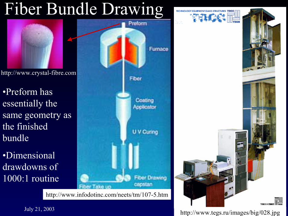
July 21, 2003 18http://www.tegs.ru/images/big/028.jpg
•Preform has essentially the same geometry as the finished bundle
•Dimensional drawdowns of 1000:1 routine
http://www.crystal-fibre.com
http://www.infodotinc.com/neets/tm/107-5.htm

July 21, 2003 19

July 21, 2003 20
First Example: Interferometric Acceleration
(Inverse Transition Radiation Acceleration)
Interaction Length : ~1000 ��~0.1 ZR
z
Terminating Boundary
E1
E2
E1zE2z
E1x
E2x
x
E1x + E2x = 0
|E1z + E2z| > 0
no transverse deflection
nonzero electric field in the direction of propagation
Slit Width ~10 �
Slit Width ~10 �
Electron beam
Waist size: wo~100 �
Crossing angle:
Terminating Boundary
The laser beams are polarized in the XZ plane, and are out of phase by �
Gradient limited to �70 MeV/m for ��� [R. Noble, 2001].

July 21, 2003 21
Ez1
Ex1E1
Z1 Z2
� �� � � � ))cos()(sin(exp
)cos(exp
121
21
21
101
21
21
1
01
21
1
tZz
twr
kwxE
z
twr
wwE
x
R
o
E
E
��
�
���
��
oRRt ZzwZrztkz ��� ������ )/(tan)/( 1
121
2111
(paraxial approximation to first order in 1/wok ~ 10-3)
P. Sprangle, E. Esarey, J. Krall, A. Ting, Opt. Comm., 124, p.69ff, (1996).

July 21, 2003 22
The LEAP CellEntrance Slit
Exit Slit
(Numerical Integration)
Ez[MV/m]
Ex[kV/m]
Ez[MV/m]
(SEK, analytic)
Analytic theory (Sprangle/Esarey/Krall/Ting 1996, green trace), and numerically integrated synchronous longitudinal (blue) and transverse (red) fields of crossed TEM00 modes. Beam slits are not accounted for in this theory.
July 21, 2003 23
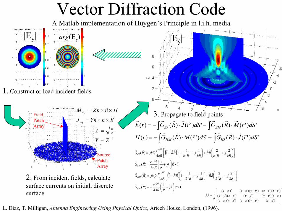
A Matlab implementation of Huygen’s Principle in l.i.h. media
� �
� �
1ˆ14
)(
22ˆˆ111ˆˆ14
)(
1ˆ14
)(
22ˆˆ111ˆˆ14
)(
2222
2222
���
���
���
���
���
���
��
��
��
���
���
����
�
���
�
���
���
��
��
��
���
���
����
�
���
�
�
�
�
�
RjkRR
eRG
kRj
RkRR
kRj
RkRR
ReYjkRG
RjkRR
eRG
kRj
RkRR
kRj
RkRR
RejkZRG
jkR
EM
jkR
oHM
jkR
EM
jkR
EJ
�
�
�
�
���
�
�
���
�
�
�����
�����
�����
�2
2
2
)'()')('()')('()')('()'()')('()')('()')('()'(
1ˆˆ
zzyyzzxxzzzzyyyyxxyyzzxxyyxxxx
RRR
|Ey|
3. Propagate to field points
1. Construct or load incident fields
EnnYJ
HnnZM
eq
eq��
��
���
���
ˆˆ
ˆˆ
1��
�
ZY
Z�
�
Source Patch Array
Field Patch Array
|Ey| arg(Ey)
2. From incident fields, calculate surface currents on initial, discrete surface
��
�������
�����
')'()(')'()()(
')'()(')'()()(
dSrJRGdSrMRGrH
dSrMRGdSrJRGrE
HJHM
EMEJ
�
���
�
����
�
���
�
����
L. Diaz, T. Milligan, Antenna Engineering Using Physical Optics, Artech House, London, (1996).

July 21, 2003 24
The LEAP CellAnalytic Theory Vector Diffraction Calculation
Entrance Slit
Entrance Slit
Synchronous Ez
Synchronous Ex
Entrance Slit
Exit Slit

July 21, 2003 25
Rayleigh-Helmholtz Reciprocity Theorem(one of many reciprocity relations)
Colloquial version: Mutual inductance is reciprocal when no nonlinear media are present. (paraphrase of J. D. Kraus, Antennas, 2nd Ed., McGraw-Hill, New York, p.410-11, (1950), with nonlinear media clause coming from J. R. Carson, “Reciprocal Theorems in Radio Communication”, Proc. IRE, 17(6), p.952ff, (1929).)
Colloquial Version, Narrowly Applied to Accelerators: If a structure accelerates beam, it will make the beam radiate, and the narrowband coupling impedance for each process will be the same.
Rigorous, general version: Given imposed quasistationary drive fields Eo’ and Eo
’’ on two objects and a bounding surface S containing both objects within volume V, and ���, and � are all scalar and constant: (from S. Ballantine, Proc. IRE, 17(6), p.929ff, (1929).)
Original version: “Let there be two circuits of insulated wire A and B and in their neighborhood any combination of wire circuits or solid conductors in communication with condensers. A periodic electromotive force in the circuit A will give rise to the same current in B as would be excited in A if the electromotive force operated in B.” Lord J. W. S. Rayleigh, Theory of Sound, v. II, Dover: New York, p. 145,(1894).
HC
dSnHEHEcdvCoECoEc ���
�� ��������
�
�
4
]''''''[4]''''''[

July 21, 2003 26
Real(Ex) Abs(Ex)Real(E
�)
Far-field CTR From Slit
Crossed-Beam Accelerator CTR Radiator, viewed narrowband
Crossed Gaussian beams, w0=64���� 10��x ����x ���bunch, 104 particles
���� ��mr
EkYH
cRK
czj
cejE
cRK
czj
Ryx
ceE
iiN
i oz
iiN
i i
ii
oyx
��
��
��
�
�
�
�
�
�
�
ˆ
)()exp(24
)()exp(2},{4
0
10
1222
1
10
122},{
4
4
��
�
�
�
�����
�
��
�
�
�
�����
�

July 21, 2003 27
Crossed Gaussian and ICTRgive qualitatively similar accelerating fields
Entrance Slit
Entrance Slit
Crossed Gaussian Synchronous Ez
ICTR Synchronous EzNote: don’t take vertical scales too seriously

July 21, 2003 28
TABLE A.1: Summary of crossed-Gaussian laser and field parameters. Parameter Symbol Value
Future Value Now
Comment
Electron Energy Ee 60 MeV 60 MeV Laser Wavelength �� 0.8 �m 0.8 �m Laser focal spot size wo 50 � 50 � Rayleigh Range zR ����mm� ����mm�
Slippage Length zs 2.8 mm 2.8 mm Ideal Crossing Angle � 11.5 mrad 11.5 mrad
Critical Energy �c 68 68 (34 MeV) Spot size on dielectric surface w1 51.3 �� 51.3 ��
Fluence x time on dielectric surface
F·t 2 J/cm2 0.5 J/cm2
Laser Pulse Energy E� 100 �J 25 �J Laser Pulse Length t 100 fsec 5 psec FWHM Peak Electric Field Eo 5.9 GV/m 0.42 GV/m Peak Axial Field Ez 140 MV/m 9.8 MV/m Energy Gain W 290 keV 20 keV Ideal phase particle Electron Beam Energy Spread �� 20 keV 20 keV FWHM
1/�=8.3 mrad
But it should be noted that ����x10-4 ����

July 21, 2003 29
DIA=1.4�
Zc=19.5��g=0.58
1.305�
�r=2.13 (Silica)
X. (Eddie) Lin, “Photonic Band Gap Fiber Accelerator”, Phys. Rev. ST-AB, 4, 051301, (2001).
•Can be designed to support a single, confined, synchronous mode
•All other modes at all other frequencies radiate strongly PE
Zc 2
22acc �
�

July 21, 2003 30
2D Photonic Band Gap Structures
0
0.2
0.4
0.6
0.8
1
TE Band Structure of Crystal
�a/
2 �c
Position around Brillouin Zone Edge
2D TE Band Gap
guidepad
e-beam
a=0.36�
w=1.08��=0.09
r=12.1 (Silicon)
This geometry is designed for the lithographic process.Ben Cowan, ARDB, SLAC

July 21, 2003 31
Impedance and Gradient Optimization
0 0.05 0.1 0.15 0.2 0.250.1
0.15
0.2
0.25
0.3
0.35
0.4
0.45
� /a
f D
Damage Factor vs. Pad and Guide Widths
w = 3.0aw = 4.0aw = 5.0aw = 6.0a
Eaccel/Epeak
�/a
1 1.2 1.4 1.6 1.8 2 2.2 2.4 2.60
50
100
150
200
250
300
w/�
Z c [ �]
PC Waveguide Shunt Impedance for SOL Modes
55.3
~�
��
���
�
�
wZc
w/a
0 0.05 0.1 0.15 0.2 0.250.03
0.04
0.05
0.06
0.07
0.08
0.09
� /a
E zmax
/Ep
Maximum Accelerating Gradient for 25 mm Segment
w = 3.0aw = 4.0aw = 5.0aw = 6.0a
�/aAssuming 1ps laser pulse
Ben Cowan, ARDB, SLAC

July 21, 2003 32
-1 -0.8 -0.6 -0.4 -0.2 0-60
-50
-40
-30
-20
-10
0
log10(r/R )
Azi
mut
hal m
ode
ampl
itude
(dB
)
R = 0 .52a
m = 0m = 1m = 2m = 3m = 4m = 6m = 12
-1 -0.8 -0.6 -0.4 -0.2 0-60
-50
-40
-30
-20
-10
0
log10(r/R )
R = 1.34a
m = 0m = 1m = 2m = 5m = 6m = 12
-1 -0.8 -0.6 -0.4 -0.2 0-60
-50
-40
-30
-20
-10
0
log10(r/R )
R = 2.1a
m = 0m = 2m = 4m = 6m = 11m = 12
Zc=1.5�Zc=22� Zc=5�
Log10(r/R) Log10(r/R) Log10(r/R)
Azi
mut
hal M
ode
Am
plitu
de [d
B]
Azi
mut
hal M
ode
Am
plitu
de [d
B]
Azi
mut
hal M
ode
Am
plitu
de [d
B]
This geometry is designed for the fiber drawing process.
Mehdi Javanmard, ARDB, SLAC

July 21, 2003 33
a b
c d
P. Russell, “Holey fiber concept spawns optical-fiber rennaissance”, Laser Focus World, Sept. 2002, p. 77-82.
PCF structures vary according to application: (a) highly nonlinear fiber; (b) endlessly single-mode fiber; (c) polarization maintaining fiber; (d) high NA fiber. From René Engel Kristiansen (Crystal Fibre A/S), “Guiding Light with Holey Fibers,” OE Magazine June 2002, p. 25.

July 21, 2003 34
Hollow Fiber Bragg Accelerator Hollow Fiber Bragg Accelerator
Rint
R�
��
R�
��
2
��
2
R�
��
2
��
2
# Concentric layers (1,2)
# Each layer
# vph = c
/ 4 1� � ��
int 00.3R ��
int 00.8R ��
Levi Schächter, The Technion

July 21, 2003 35

July 21, 2003 36
L
max1 sin2
cosf �
��
��
phase advance/half-cell� �
mcfeGl�
�
fIf a is the beam hole radius, the acceptance is
2
max
clearance = 25 for 5 beam
IaA n
n
�
� �
�
� �
�
For a quad of length l and gradient G2 cos
2 1 sinIa eGln mc
��
��
�
����
�
�
4
4
10725;4.22.193.145
36.1102;0.1;/5.2
�
������
���
������
I
o
nmamL
mfcmlmkTG
mm-mr
Example
R. Siemann, ARDB

July 21, 2003 37
While �N=7x10⁻⁴� mm-mr is a very small emittance, the phase space density
Q/�N=5x105e/7x10-4 = 0.12 nC/mm-mr, an order of magnitude lower than the phase space densities demonstrated by rf photoinjectors now.
RF Gun
Superconducting Linac at 3rd Harmonic
IFEL Optical Buncher
First pass PARMELA simulations show this emittance is not unreasonable.
July 21, 2003 38
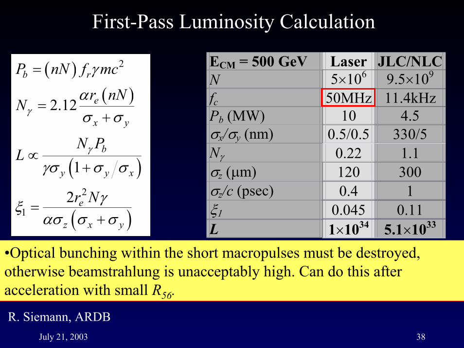
First-Pass Luminosity Calculation
� � 2b rP nN f mc��
� �2.12 e
x y
r nNN
�
�
� �
�
�
� �
2
12 e
z x y
r N��
�� � ��
�
� �1b
y y x
N PL �
�� � ��
�
•Optical bunching within the short macropulses must be destroyed, otherwise beamstrahlung is unacceptably high. Can do this after acceleration with small R56.
ECM = 500 GeV Laser JLC/NLCN 5�106 9.5�109 fc 50MHz 11.4kHz Pb (MW) 10 4.5 �x/�y (nm) 0.5/0.5 330/5 N�� 0.22 1.1 �z (�m) 120 300 �z/c (psec) 0.4 1 �� 0.045 0.11 L 1�1034 5.1�1033
R. Siemann, ARDB

July 21, 2003 39
Laser Linear Collider Cartoon
CW InjectorWarm rf gun Cold Preaccelerator Optical Buncher433 MHz x 5E05 e-/macropulse (600 �pulse/macropulse)�N~10-11 m (but note Q/�N ~ 1 �m/nC)
Photonic Band Gap Fiber str
…
Laser Accelerator��1-2 ���G~1 GeV/m
uctures embedded in optical resonant ringsPermanent Magnet Quads (B’~2.5 kT/m)
…
PBG accelerator structure
Phase control
Resonant ring path length: �rf=23 cmAn Acceleration Unit
Laser amplifier
Optical resonator
Optical Debuncher Final Focus I.P.
July 21, 2003 40
July 21, 2003 41
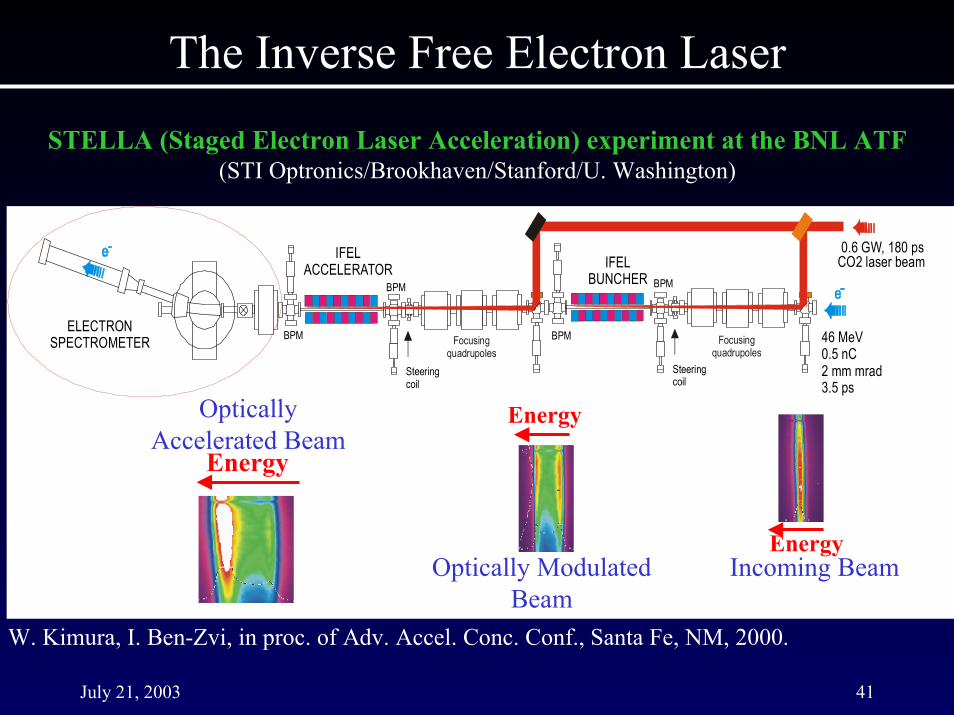
The Inverse Free Electron Laser
STELLA (Staged Electron Laser Acceleration) experiment at the BNL ATF(STI Optronics/Brookhaven/Stanford/U. Washington)
CO2 laser beam
ELECTRONSPECTROMETER
IFELACCELERATOR IFEL
BUNCHER
46 MeV 0.5 nC 2 mm mrad 3.5 ps
0.6 GW, 180 ps
Steeringcoil
BPM
BPM
BPM
BPM
Focusingquadrupoles
Steeringcoil
Focusingquadrupoles
Energy
Energy
EnergyIncoming BeamOptically Modulated
Beam
Optically Accelerated Beam
W. Kimura, I. Ben-Zvi, in proc. of Adv. Accel. Conc. Conf., Santa Fe, NM, 2000.
July 21, 2003 42
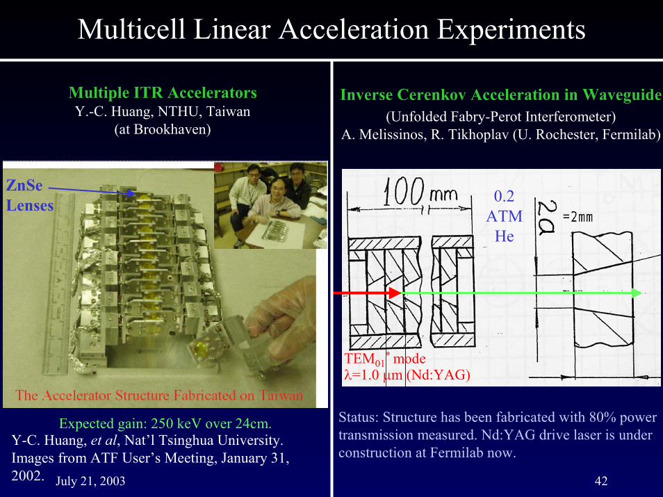
Multicell Linear Acceleration Experiments
Inverse Cerenkov Acceleration in Waveguide(Unfolded Fabry-Perot Interferometer)
A. Melissinos, R. Tikhoplav (U. Rochester, Fermilab)
TEM01* mode
�=1.0 �m (Nd:YAG)
0.2 ATM
He
Status: Structure has been fabricated with 80% power transmission measured. Nd:YAG drive laser is under construction at Fermilab now.
Multiple ITR AcceleratorsY.-C. Huang, NTHU, Taiwan
(at Brookhaven)
ZnSe Lenses
Y-C. Huang, et al, Nat’l Tsinghua University. Images from ATF User’s Meeting, January 31, 2002.
Expected gain: 250 keV over 24cm.

July 21, 2003 43
“Laser Electron Acceleration Project”
Stanford University (Appl Phys. & HEPL) / SLACcrossed
laser beams
electronbeam
Fused silica prisms and flats
High Reflectance Dielectric coated surfaces
Accelerator cell
slit
Computed Field Intensity, |Et|2
~1 cm

July 21, 2003 44
Electron Beam
1 cm

July 21, 2003 45
crossedlaser beams
electronbeam
acceleratorcell
~ 1 cm
crossedlaser beams
electronbeam
crossedlaser beams
electronbeam
crossedlaser beams
electronbeam
acceleratorcell
Imageintensifiedcamera
doped YAGscreen
spectrometermagnet
Diagnostics:•spatial monitor•streak camera
~ 1 m
Imageintensifiedcamera
doped YAGscreen
spectrometermagnet
Diagnostics:•spatial monitor•streak camera
Camera
Electron beam
Vacuum chamber
July 21, 2003 46
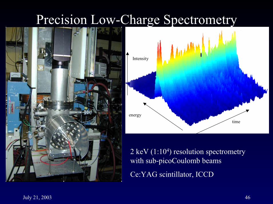
Precision Low-Charge Spectrometry
timeenergy
2 keV (1:104) resolution spectrometry with sub-picoCoulomb beams
Ce:YAG scintillator, ICCD
Intensity

July 21, 2003 47
Three separate systems used, depending on circumstances
1. Coarse Timing (~1 nanosecond scale) PMT watches for bremstrahlung xrays from the beam Photodiode watches the laser
�signals summed and transmitted on common cable; scope observation
2. Fine Timing (~5 picosecond resolution; relative, nondestructive)Rf cavity samples 11.8 MHz beam at 238th harmonic (2.812 GHz)Photodiode observes laser (82.7 MHz), generate 34th harmonic (2.812 GHz)
�Phase comparison at 2.812 GHz, signal chopped at ~12 kHz and synchronously detected
3. Fine Timing (~50 picosecond resolution; absolute, destructive)Aerogel cell generates Cerenkov radiation from single e- pulseLaser passes through optically transmissive Cerenkov cell
� C1587 Streak Camera (�t=2 psec) observes both signals

July 21, 2003 48
Laser and Electron Beam Timing and Position Overlap Diagnostics
pellicle YAG screenholder
electronbeam
HAMAMATSUC-1587
streakcamera
tiltstage
intensifiedgain camera
XYBION1SG350-U-E Cerenkov
cell

July 21, 2003 49
E163: Laser Acceleration of Electrons at the NLCTA
• Create an extraction line in a separate hall attached to the NLCTA to test candidate laser acceleration structures– Phase I: Install the LEAP Crossed-Gaussian accelerator,
commission the beamline, and complete the physics study of interferometric (ITR) acceleration
– Phase II: Install an IFEL prebuncher, and conduct the first acceleration experiments, using the LEAP cell, or candidate single-cell PBG structures
�With the completion of Phase II, the facility will then host the world’s highest brightness 0.8 �m electron injector
– Phase III: Test multicell PBG structures
July 21, 2003 50
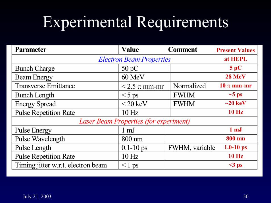
Parameter Value Comment Electron Beam Properties
Bunch Charge 50 pC Beam Energy 60 MeV Transverse Emittance < 2.5 � mm-mr Normalized Bunch Length < 5 ps FWHM Energy Spread < 20 keV FWHM Pulse Repetition Rate 10 Hz
Laser Beam Properties (for experiment) Pulse Energy 1 mJ Pulse Wavelength 800 nm Pulse Length 0.1-10 ps FWHM, variable Pulse Repetition Rate 10 Hz Timing jitter w.r.t. electron beam < 1 ps
Present Valuesat HEPL
5 pC28 MeV
10 � mm-mr~5 ps
~20 keV10 Hz
1 mJ800 nm
1.0-10 ps10 Hz<3 ps

July 21, 2003 51
Next Linear Collider Test Accelerator (NLCTA)E163/ORION RF Electron Gun (UCLA/SLAC)
LEAP Apparatus

July 21, 2003 52
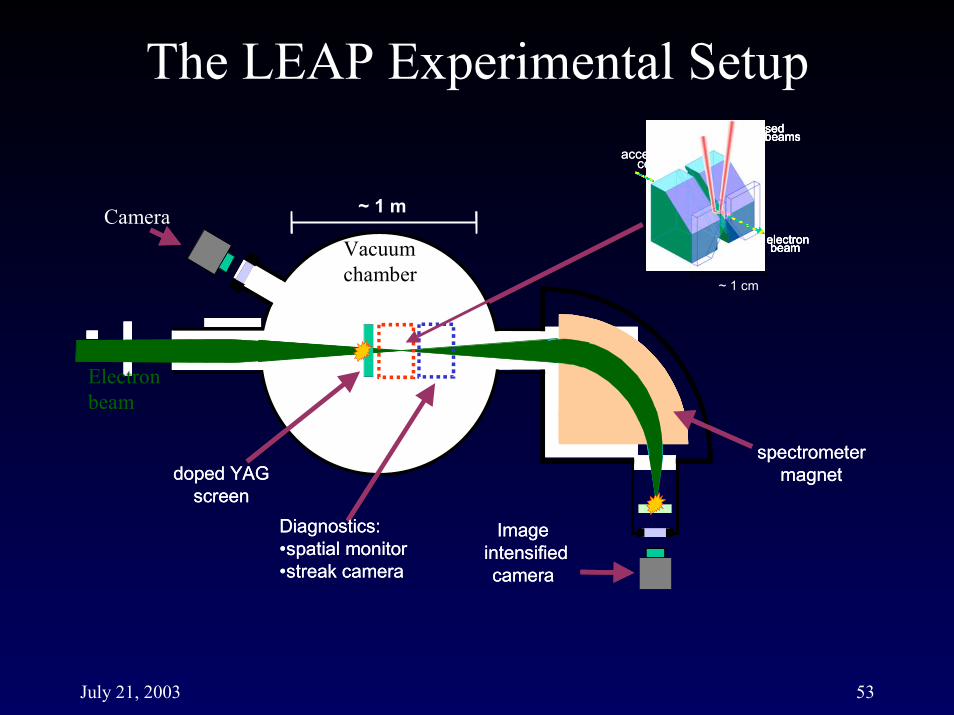
July 21, 2003 53
crossedlaser beams
electronbeam
acceleratorcell
~ 1 cm
crossedlaser beams
electronbeam
crossedlaser beams
electronbeam
crossedlaser beams
electronbeam
acceleratorcell
Imageintensifiedcamera
doped YAGscreen
spectrometermagnet
Diagnostics:•spatial monitor•streak camera
~ 1 m
Imageintensifiedcamera
doped YAGscreen
spectrometermagnet
Diagnostics:•spatial monitor•streak camera
Camera
Electron beam
Vacuum chamber
July 21, 2003 54
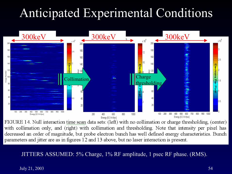
Collimation Charge thresholding
300keV 300keV 300keV
JITTERS ASSUMED: 5% Charge, 1% RF amplitude, 1 psec RF phase. (RMS).

July 21, 2003 55
Ce:YAG crystal jaws
Pole-tip wedges

July 21, 2003 56
Results from Last LEAP Run (June 2002)C:\Laser Acceleration\June2002 284
Shot
Num
ber
(1)
Energy Profile100 200 300 400 500 600 700 800
200
400
600
800
1000
1200
1400
1600
18000 0.5 1 1.5 2 2.5 3 3.5 4
x 106
0
20
40
60
80
100
120
140
160
180
Means & RMS: 1.02 +/− 0.40 x10 6
C:\Laser Acceleration\June2002 284
AxCV (13)
His
togr
am
10−Jul−2002−14:30
No cuts applied
C:\Laser Acceleration\June2002 284
Tim
e(ps
ec)
(2)
Energy Profile320 340 360 380 400 420 440 460 480 500
230
240
250
260
270
280
Analyzer magnetchange
Beam charge histogram
18 keVBeam
charge cut&
normalized to charge
720keV
Q
N

July 21, 2003 57
Simulated Optical Modulation Experiment (Phase I)
JITTER ASSUMED: 5% Charge, 1% RF amplitude, 1 psec RF phase. (RMS).

July 21, 2003 58
Simulated Optical Bunching and Acceleration Experiment (Phase II)
(1)Bunching
Phase
(2)Decelerating
Phase
(3)Debunching
Phase
(4)Accelerating
Phase
FIGURE 16. Charge density (left), simulated phase scan with jitter added (center), covering 10 ��of variation in the relative phase between IFEL and laser accelerator, and averaged spectra (right) at (1) bunching, (2) decelerating, (3) debunching, and (4) accelerating phase.
JITTER ASSUMED: 1% RF amplitude, 1 psec RF phase, 5% Charge. (RMS).
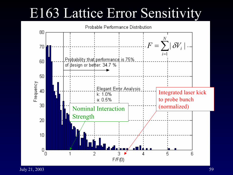
July 21, 2003 59
Integrated laser kick to probe bunch (normalized)
��
�
N
iiVF
1||�
Nominal Interaction Strength

July 21, 2003 60
7/16/03
↑Entrance labyrinth Inside↗
Outside→
July 21, 2003 61
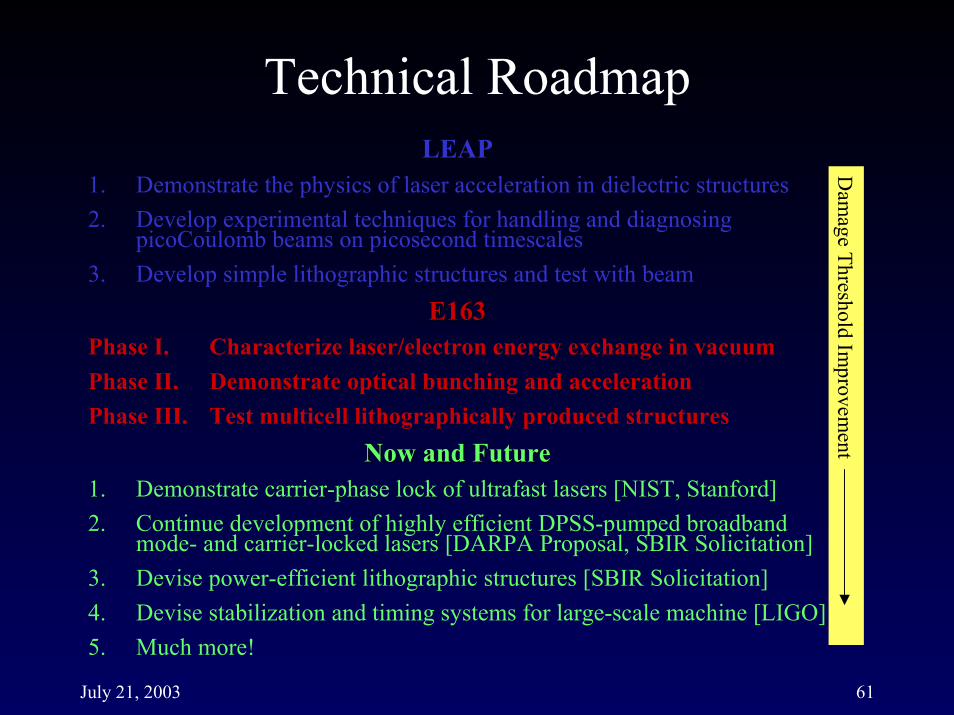
LEAPLEAP1. Demonstrate the physics of laser acceleration in dielectric structures 2. Develop experimental techniques for handling and diagnosing
picoCoulomb beams on picosecond timescales3. Develop simple lithographic structures and test with beam
E163E163Phase I. Characterize laser/electron energy exchange in vacuumPhase II. Demonstrate optical bunching and accelerationPhase III. Test multicell lithographically produced structures
Now and FutureNow and Future1. Demonstrate carrier-phase lock of ultrafast lasers [NIST, Stanford]2. Continue development of highly efficient DPSS-pumped broadband
mode- and carrier-locked lasers [DARPA Proposal, SBIR Solicitation]3. Devise power-efficient lithographic structures [SBIR Solicitation]4. Devise stabilization and timing systems for large-scale machine [LIGO]5. Much more!
Dam
age Threshold Improvem
ent

July 21, 2003 62
High Average Power Diode Pumped Solid State Lasers
Stanford University (SPRC)
Power Scaling with high spectral and spatial coherence
Research Objectives:•to improve the efficiency of diode pumped solid state lasers such as in-band pumping, reduction of loss in the laser materials, improved pumped efficiency, and operation of phased array spatial mode lasers.
•to scale the average power while maintaining coherence by extending the master oscillator, power amplifier approach to encompass cw, energy storage, and ultrafast pulse format operation.
Stanford Research Program (DARPA)A. High Average Power CW Lasers
B. High energy Yb:YAG lasers for Remote Sensing
C. High average power ultrafast lasers
D. Optical damage and plasma studies with ultrafast lasers
July 21, 2003 63
Rapid, market-driven development has pushed lasers into competitive standing with microwave tubes with regard to average power, efficiency, and control, but with peak powers and field strengths that are vastly superior.
Efficient power coupling between optical fields and beam must be demonstrated in an energy- and economically-scalable structure
�LEAP, E163, and the follow-on ORION VLA program
Continued laser development to produce lasers with all properties matched to accelerator requirements is needed
�DARPA-funded program at Stanford
Continued work on higher damage threshold, linear materials is highly desirable
�SPRC work on damage studies and optical ceramics

July 21, 2003 64
“One of the authors (W.W.H.), in his study of cavity resonators, was motivated by a desire to find a cheap method of obtaining high energy electrons. This cavity acceleration work was put aside, largely because of the change in standard of success caused by the advent of Kerst’s betatron. . .
. . .By the end of the war many people were interested [in linear acceleration], possible reasons being: (a) wide-spread knowledge of cavity properties and technique, (b) the enormous pulsed powers made available by radar developments.”
- E. L. Ginzton, W. W. Hansen, W. R. Kennedy, “A Linear Electron Accelerator”, Rev. Sci. Inst., 19(2), p. 89, February 1948.