laser measurement and control - coherent, inc. measurement and control 2016/2017 product catalog...
TRANSCRIPT
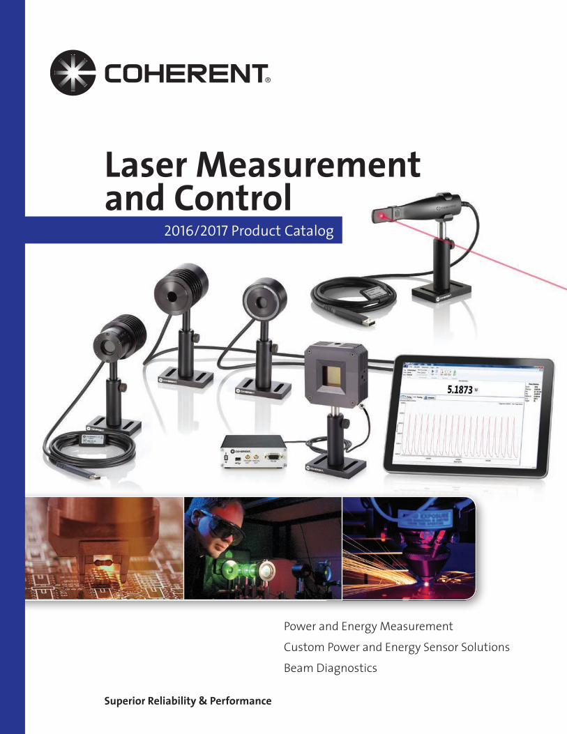
Laser Measurementand Control
2016/2017 Product Catalog
Superior Reliability & Performance
Power and Energy Measurement
Custom Power and Energy Sensor Solutions
Beam Diagnostics
Technical Support
OperationalExcellence
Superior C
usto
mer
Serv
ice
Warranty
On-Time Delivery
C24
Prog
ram
Product Reliability
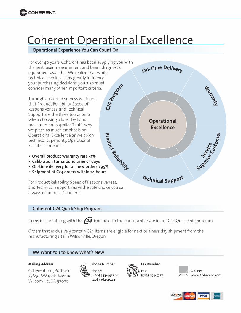
For over 40 years, Coherent has been supplying you with the best laser measurement and beam diagnostic equipment available. We realize that while technical specifications greatly influence your purchasing decisions, you also must consider many other important criteria.
Through customer surveys we found that Product Reliability, Speed of Responsiveness, and Technical Support are the three top criteria when choosing a laser test and measurement supplier. That’s why we place as much emphasis on Operational Excellence as we do on technical superiority. Operational Excellence means:
• Overall product warranty rate <1%• Calibration turnaround time <5 days• On-time delivery for all new orders >95%• Shipment of C24 orders within 24 hours
For Product Reliability, Speed of Responsiveness, and Technical Support, make the safe choice you can always count on – Coherent.
Items in the catalog with the icon next to the part number are in our C24 Quick Ship program.
Orders that exclusively contain C24 items are eligible for next business day shipment from the manufacturing site in Wilsonville, Oregon.
Coherent Inc., Portland27650 SW 95th AvenueWilsonville, OR 97070
Phone NumberMailing Address Fax Number
Coherent Operational ExcellenceOperational Experience You Can Count On
Coherent C24 Quick Ship Program
We Want You to Know What’s New
Phone: Fax: Online: (800) 343-4912 or (503) 454-5727 www.Coherent.com(408) 764-4042
1• Toll Free: (800) 343-4912 • Tel: (408) 764-4042 • Fax: (503) 454-5727
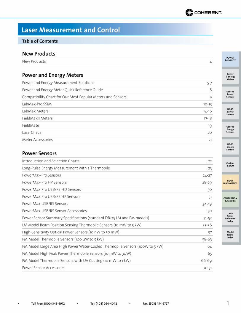
New ProductsNew Products 4
Power and Energy MetersPower and Energy Measurement Solutions 5-7
Power and Energy Meter Quick Reference Guide 8
Compatibility Chart for Our Most Popular Meters and Sensors 9
LabMax-Pro SSIM 10-13
LabMax Meters 14-16
FieldMaxII Meters 17-18
FieldMate 19
LaserCheck 20
Meter Accessories 21
Power SensorsIntroduction and Selection Charts 22
Long-Pulse Energy Measurement with a Thermopile 23
PowerMax-Pro Sensors 24-27
PowerMax-Pro HP Sensors 28-29
PowerMax-Pro USB/RS HD Sensors 30
PowerMax-Pro USB/RS HP Sensors 31
PowerMax-USB/RS Sensors 32-49
PowerMax-USB/RS Sensor Accessories 50
Power Sensor Summary Specifications (standard DB-25 LM and PM models) 51-52
LM Model Beam Position Sensing Thermopile Sensors (10 mW to 5 kW) 53-56
High-Sensitivity Optical Power Sensors (10 nW to 50 mW) 57
PM Model Thermopile Sensors (100 µW to 5 kW) 58-63
PM Model Large Area High Power Water-Cooled Thermopile Sensors (100W to 5 kW) 64
PM Model High Peak Power Thermopile Sensors (10 mW to 30W) 65
PM Model Thermopile Sensors with UV Coating (10 mW to 1 kW) 66-69
Power Sensor Accessories 70-71
Table of Contents
Laser Measurement and Control
POWER & ENERGY
Custom & OEM
BEAM DIAGNOSTICS
CALIBRATION & SERVICE
Power & Energy
Meters
Laser Cross-
Reference Index
Model Name Index
DB-25Energy Sensors
USB/RSEnergy Sensors
DB-25Power
Sensors
USB/RSPower
Sensors
2 Superior Reliability & Performance • www.Coherent.com • [email protected]
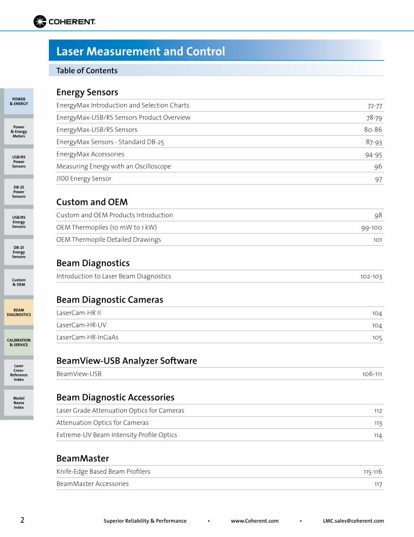
Energy SensorsEnergyMax Introduction and Selection Charts 72-77
EnergyMax-USB/RS Sensors Product Overview 78-79
EnergyMax-USB/RS Sensors 80-86
EnergyMax Sensors - Standard DB-25 87-93
EnergyMax Accessories 94-95
Measuring Energy with an Oscilloscope 96
J100 Energy Sensor 97
Custom and OEMCustom and OEM Products Introduction 98
OEM Thermopiles (10 mW to 1 kW) 99-100
OEM Thermopile Detailed Drawings 101
Beam DiagnosticsIntroduction to Laser Beam Diagnostics 102-103
Beam Diagnostic CamerasLaserCam-HR II 104
LaserCam-HR-UV 104
LaserCam-HR-InGaAs 105
BeamView-USB Analyzer SoftwareBeamView-USB 106-111
Beam Diagnostic AccessoriesLaser Grade Attenuation Optics for Cameras 112
Attenuation Optics for Cameras 113
Extreme-UV Beam Intensity Profile Optics 114
BeamMasterKnife-Edge Based Beam Profilers 115-116
BeamMaster Accessories 117
POWER & ENERGY
Custom & OEM
BEAM DIAGNOSTICS
CALIBRATION & SERVICE
Power & Energy
Meters
Table of Contents
Laser Measurement and Control
Laser Cross-
Reference Index
Model Name Index
DB-25Energy Sensors
USB/RSEnergy Sensors
DB-25Power
Sensors
USB/RSPower
Sensors
3• Toll Free: (800) 343-4912 • Tel: (408) 764-4042 • Fax: (503) 454-5727
ModeMaster PCM2 Beam Propagation Analyzer 118-123
WaveMasterLaser Wavelength Meter 124-125
ISO 17025, Calibration, Warranty and Service 126-127
Measurement Products for Use with Coherent Lasers 128-130
Model Name Index 131-132
Doing Business with Coherent 135
How to Contact Us 136
Visit the Coherent Website Inside Back Cover
POWER & ENERGY
Custom & OEM
BEAM DIAGNOSTICS
CALIBRATION & SERVICE
Power & Energy
Meters
Table of Contents
Laser Measurement and Control
Laser Cross-
Reference Index
Model Name Index
DB-25Energy Sensors
USB/RSEnergy Sensors
DB-25Power
Sensors
USB/RSPower
Sensors
4 Superior Reliability & Performance • www.Coherent.com • [email protected]
PowerMax-Pro USB/RS Sensors
New to the Catalog
New Products
POWER & ENERGY
Custom & OEM
BEAM DIAGNOSTICS
CALIBRATION & SERVICE
Power & Energy
Meters
Laser Cross-
Reference Index
Model Name Index
DB-25Energy Sensors
USB/RSEnergy Sensors
DB-25Power
Sensors
USB/RSPower
Sensors
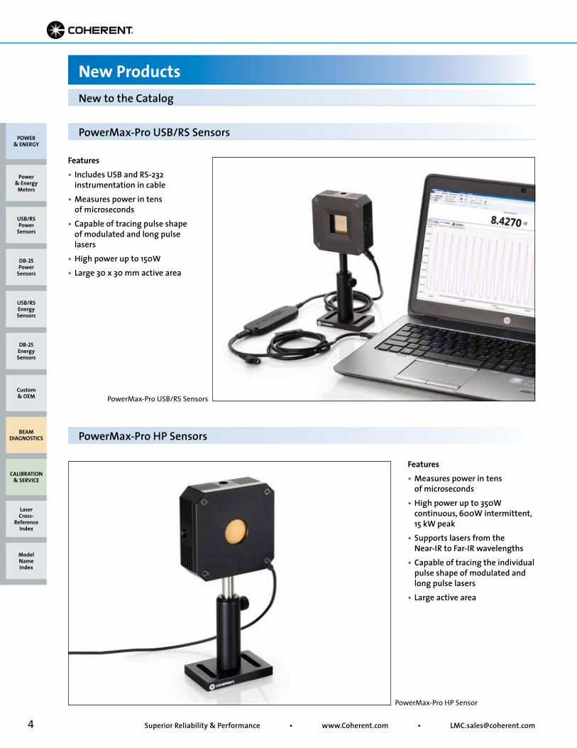
PowerMax-Pro USB/RS Sensors
PowerMax-Pro HP Sensor
PowerMax-Pro HP Sensors
Features• Includes USB and RS-232 instrumentation in cable• Measures power in tens of microseconds• Capable of tracing pulse shape of modulated and long pulse lasers• High power up to 150W• Large 30 x 30 mm active area
Features• Measures power in tens of microseconds• High power up to 350W continuous, 600W intermittent, 15 kW peak• Supports lasers from the Near-IR to Far-IR wavelengths• Capable of tracing the individual pulse shape of modulated and long pulse lasers• Large active area
5• Toll Free: (800) 343-4912 • Tel: (408) 764-4042 • Fax: (503) 454-5727
Sensor Technologies
Power and Energy Measurement Solutions
POWER & ENERGY
Custom & OEM
BEAM DIAGNOSTICS
CALIBRATION & SERVICE
Power & Energy
Meters
Laser Cross-
Reference Index
Model Name Index
DB-25Energy Sensors
USB/RSEnergy Sensors
DB-25Power
Sensors
USB/RSPower
Sensors
Coherent offers four different sensor technologies (PowerMax-Pro, thermopile, semiconductor/optical, and pyroelectric) that address a broad range of measurement parameters and laser characteristics.
PowerMax-Pro
Pyroelectric
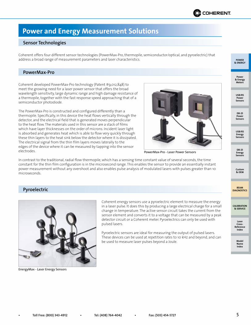
Coherent developed PowerMax-Pro technology (Patent #9,012,848) to meet the growing need for a laser power sensor that offers the broad wavelength sensitivity, large dynamic range and high damage resistance of a thermopile, together with the fast response speed approaching that of a semiconductor photodiode.
The PowerMax-Pro is constructed and configured differently than a thermopile. Specifically, in this device the heat flows vertically through the detector, and the electrical field that is generated moves perpendicular to the heat flow. The materials used in this sensor are a stack of films which have layer thicknesses on the order of microns. Incident laser light is absorbed and generates heat which is able to flow very quickly through these thin layers to the heat sink below the detector where it is dissipated. The electrical signal from the thin film layers moves laterally to the edges of the device where it can be measured by tapping into the sensor electrodes.
Coherent energy sensors use a pyroelectric element to measure the energy in a laser pulse. It does this by producing a large electrical charge for a small change in temperature. The active sensor circuit takes the current from the sensor element and converts it to a voltage that can be measured by a peak detector circuit or a Coherent meter. Pyroelectrics can only be used with pulsed lasers.
Pyroelectric sensors are ideal for measuring the output of pulsed lasers. These devices can be used at repetition rates to 10 kHz and beyond, and can be used to measure laser pulses beyond a Joule.
PowerMax-Pro - Laser Power Sensors
In contrast to the traditional, radial flow thermopile, which has a sensing time constant value of several seconds, the time constant for the thin film configuration is in the microsecond range. This enables the sensor to provide an essentially instant power measurement without any overshoot and also enables pulse analysis of modulated lasers with pulses greater than 10 microseconds.
EnergyMax - Laser Energy Sensors
6 Superior Reliability & Performance • www.Coherent.com • [email protected]
Quad Positioning
Enabled
Thermopile
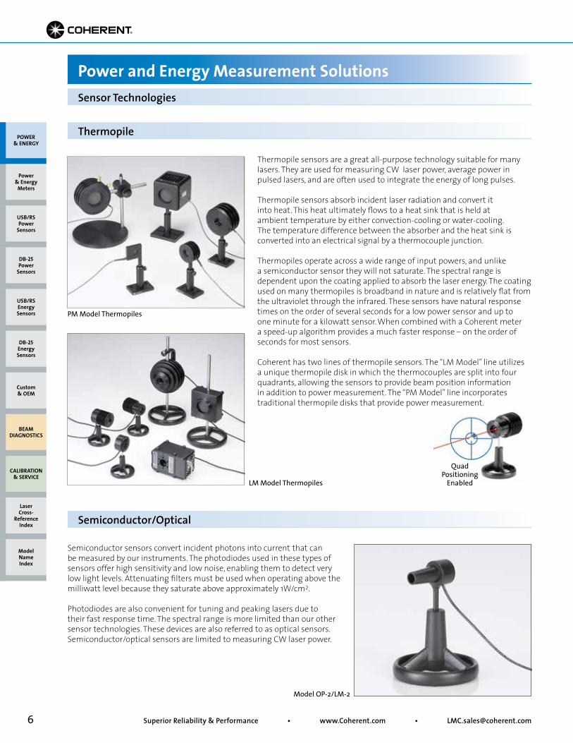
Semiconductor sensors convert incident photons into current that can be measured by our instruments. The photodiodes used in these types of sensors offer high sensitivity and low noise, enabling them to detect very low light levels. Attenuating filters must be used when operating above the milliwatt level because they saturate above approximately 1W/cm2.
Photodiodes are also convenient for tuning and peaking lasers due to their fast response time. The spectral range is more limited than our other sensor technologies. These devices are also referred to as optical sensors. Semiconductor/optical sensors are limited to measuring CW laser power.
Semiconductor/Optical
Sensor Technologies
Power and Energy Measurement Solutions
POWER & ENERGY
Custom & OEM
BEAM DIAGNOSTICS
CALIBRATION & SERVICE
Power & Energy
Meters
Laser Cross-
Reference Index
Model Name Index
DB-25Energy Sensors
USB/RSEnergy Sensors
DB-25Power
Sensors
USB/RSPower
Sensors
Thermopile sensors are a great all-purpose technology suitable for many lasers. They are used for measuring CW laser power, average power in pulsed lasers, and are often used to integrate the energy of long pulses.
Thermopile sensors absorb incident laser radiation and convert it into heat. This heat ultimately flows to a heat sink that is held at ambient temperature by either convection-cooling or water-cooling. The temperature difference between the absorber and the heat sink is converted into an electrical signal by a thermocouple junction.
Thermopiles operate across a wide range of input powers, and unlike a semiconductor sensor they will not saturate. The spectral range is dependent upon the coating applied to absorb the laser energy. The coating used on many thermopiles is broadband in nature and is relatively flat from the ultraviolet through the infrared. These sensors have natural response times on the order of several seconds for a low power sensor and up to one minute for a kilowatt sensor. When combined with a Coherent meter a speed-up algorithm provides a much faster response – on the order of seconds for most sensors.
Coherent has two lines of thermopile sensors. The “LM Model” line utilizes a unique thermopile disk in which the thermocouples are split into four quadrants, allowing the sensors to provide beam position information in addition to power measurement. The “PM Model” line incorporates traditional thermopile disks that provide power measurement.
PM Model Thermopiles
LM Model Thermopiles
Model OP-2/LM-2
7• Toll Free: (800) 343-4912 • Tel: (408) 764-4042 • Fax: (503) 454-5727
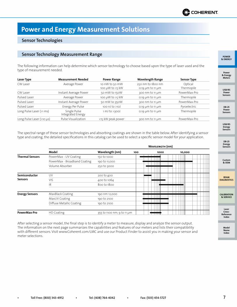
The following information can help determine which sensor technology to choose based upon the type of laser used and the type of measurement needed.
Sensor Technology Measurement Range
Laser Type Measurement Needed Power Range Wavelength Range Sensor TypeCW Laser Average Power 10 nW to 50 mW 250 nm to 1800 nm Optical 100 µW to >5 kW 0.19 µm to 11 µm ThermopileCW Laser Instant Average Power 50 mW to 150W 300 nm to 11 µm PowerMax-Pro Pulsed Laser Average Power 100 µW to >5 kW 0.19 µm to 11 µm ThermopilePulsed Laser Instant Average Power 50 mW to 350W 300 nm to 11 µm PowerMax-Pro Pulsed Laser Energy Per Pulse 100 nJ to >10J 0.19 µm to 11 µm PyroelectricLong Pulse Laser (>1 ms) Single Pulse 1 mJ to >300J 0.19 µm to 11 µm Thermopile Integrated Energy Long Pulse Laser (>10 µs) Pulse Visualization <15 kW peak power 300 nm to 11 µm PowerMax-Pro
Sensor Technologies
Power and Energy Measurement Solutions
The spectral range of these sensor technologies and absorbing coatings are shown in the table below. After identifying a sensor type and coating, the detailed specifications in this catalog can be used to select a specific sensor model for your application.
After selecting a sensor model, the final step is to identify a meter to measure, display and analyze the sensor output. The information on the next page summarizes the capabilities and features of our meters and lists their compatibility with different sensors. Visit www.Coherent.com/LMC and use our Product Finder to assist you in making your sensor and meter selections.
Model Wavelength (nm) 100 1000 10,000PowerMax - UV Coating 150 to 1000 PowerMax - Broadband Coating 190 to 11,000 Volume Absorber 250 to 3000 UV 200 to 400 VIS 400 to 1064 IR 800 to 1800 MaxBlack Coating 190 nm 12,000 MaxUV Coating 190 to 2100 Diffuse Metallic Coating 190 to 2100
HD Coating 355 to 1100 nm; 9 to 11 µm
Thermal Sensors
Semiconductor Sensors
Energy Sensors
PowerMax-Pro
Wavelength (nm)
POWER & ENERGY
Custom & OEM
BEAM DIAGNOSTICS
CALIBRATION & SERVICE
Power & Energy
Meters
Laser Cross-
Reference Index
Model Name Index
DB-25Energy Sensors
USB/RSEnergy Sensors
DB-25Power
Sensors
USB/RSPower
Sensors

8 Superior Reliability & Performance • www.Coherent.com • [email protected]
Meter Features Summary Table
Power and Energy Meter Quick Reference Guide
FieldMate FieldMaxII FieldMaxII FieldMaxII LabMax LabMax LabMax LaserCheck -TOP -TO -P -Pro SSIM -TOP -TO
Page Reference 19 17 17 17 10 14 14 20
Measurement ModesCW Power • • • • • • •
Avg. Power of Pulsed Lasers • • • • • •
Long-Pulse Joules • • • •
Pulse Energy • • •
Max. Rep. Rate (Hz) 300 300 10,0001
Display TypesDigital Readout • • • • •2 • • •
Analog Needle Tuning •
Graphical Tuning • • • •2 • •
Strip Chart/Trending •2 • •
Measurement Analysis SupportedBeam Position • •
Statistics • • • • • •
Display Smoothing • • • • • •
High Speed Power •
Correction Factors SupportedWavelength Correction • • • • • • • •
Attenuation Factor • • • • • •
PC InterfacesUSB • • • • • •
RS-232 • • •
GPIB •3
Analog Output • • • • • • •
Electrical Power OptionsBattery (rechargeable) • • • • •
Battery (non-rechargeable) • •
AC Powered • • • • • • •
Meter and Sensor Compatibility Table
Power SensorsPM Model • • • • • •
PS Model • • • • • •
OP-2 Model • • • • • •
LM Model and BeamFinder •4 •4 •4 • •
LM-2 Model •4 •4 •4 • • •
PowerMax-Pro • • • • • •
Energy SensorsEnergyMax •5 •5 • • 1 10,000 Hz sampled; 1000 Hz every pulse.2 Using PC software application.3 LabMax-TOP w/GPIB model only.4 Compatible when used with Thermal SmartSensor Adapter #1056827.
5 Our J-50MT-10KHz, J-25MT-10KHz, J-10MT-10KHz, J-10Si, and J-10Ge EnergyMax Sensors are not compatible with FieldMaxII-TOP meters. For legacy sensor models not listed, please contact Coherent or your local representative for assistance.
POWER & ENERGY
Custom & OEM
BEAM DIAGNOSTICS
CALIBRATION & SERVICE
Power & Energy
Meters
Laser Cross-
Reference Index
Model Name Index
DB-25Energy Sensors
USB/RSEnergy Sensors
DB-25Power
Sensors
USB/RSPower
Sensors
9• Toll Free: (800) 343-4912 • Tel: (408) 764-4042 • Fax: (503) 454-5727
POWER
ENERGY
Meters
Sensors
Sensors
Meters
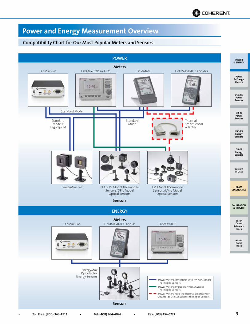
Compatibility Chart for Our Most Popular Meters and Sensors
Power and Energy Measurement Overview
POWER & ENERGY
Custom & OEM
BEAM DIAGNOSTICS
CALIBRATION & SERVICE
Power & Energy
Meters
Laser Cross-
Reference Index
Model Name Index
DB-25Energy Sensors
USB/RSEnergy Sensors
DB-25Power
Sensors
USB/RSPower
Sensors
LabMax-Pro
Power Meters compatible with PM & PS Model Thermopile Sensors Power Meter compatible with LM Model Thermopile Sensors Power Meters need the Thermal SmartSensor Adapter to use LM Model Thermopile Sensors
PM & PS Model Thermopile Sensors/OP-2 Model
Optical Sensors
PowerMax-Pro LM Model Thermopile Sensors/LM-2 Model
Optical Sensors
EnergyMax Pyroelectric
Energy Sensors
Thermal SmartSensor Adapter
FieldMaxII-TOP and -TOFieldMateLabMax-TOP and -TO
Standard Mode +
High Speed
Standard Mode
Standard Mode
LabMax-TOPLabMax-Pro FieldMaxII-TOP and -P
10 Superior Reliability & Performance • www.Coherent.com • [email protected]
POWER & ENERGY
Custom & OEM
BEAM DIAGNOSTICS
CALIBRATION & SERVICE
Power & Energy
Meters
Laser Cross-
Reference Index
Model Name Index
DB-25Energy Sensors
USB/RSEnergy Sensors
DB-25Power
Sensors
USB/RSPower
Sensors
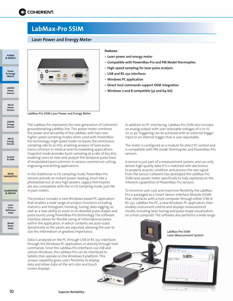
LabMax-Pro SSIMLaser Power and Energy Meter
Features• Laser power and energy meter• Compatible with PowerMax-Pro and PM Model thermopiles• High speed sampling for laser pulse analysis• USB and RS-232 interfaces• Windows PC application• Direct host commands support OEM integration• Windows 7 and 8 compatible (32 and 64-bit)
The LabMax-Pro represents the next generation of Coherent’s groundbreaking LabMax line. This power meter combines the power and versatility of the LabMax, with two new higher speed sampling modes when used with PowerMax-Pro technology. High speed mode increases the continuous sampling rate to 20 kHz, enabling analysis of laser pulse trains common in medical and microwelding applications. Snapshot mode provides burst sampling at a rate of 625 kHz, enabling users to view and analyze the temporal pulse trace of modulated lasers common in various commercial cutting, engraving and drilling applications.
In the traditional 10 Hz sampling mode, PowerMax-Pro sensors provide an instant power reading, much like a photodiode but at very high powers. Legacy thermopilesare also compatible with the 10 Hz sampling mode, just like in past meters.
The product includes a new Windows-based PC application that enables a wide range of analysis functions including statistics and histogram, trending, tuning, data logging, as well as a new ability to zoom in on detailed pulse shapes andpulse bursts using PowerMax-Pro technology. The software interface allows for flexible sizing of informational panes within the application, in which contents are auto-sized dynamically as the panes are adjusted, allowing the user to size the information of greatest importance.
Data is analyzed on the PC through USB or RS-232 interfaces through the Windows PC application, or directly through host commands. Since the LabMax-Pro interfaces via USB and utilizes Windows, the LabMax-Pro can be interfaced to tablets that operate on the Windows 8 platform. This unique capability gives users flexibility to display data and allow state-of-the-art color and touch screen displays.
In addition to PC interfacing, LabMax-Pro SSIM also includes an analog output with user-selectable voltages of 0 to 1V, 2V, or 4V. Triggering can be achieved with an external trigger input or an internal trigger that is user adjustable.
The meter is configured as a module for direct PC control and is compatible with PM model thermopiles and PowerMax-Pro sensors.
A sensor is just part of a measurement system, and can only deliver high quality data if it is matched with electronics to properly acquire, condition and process the raw signal from the sensor. Coherent has developed the LabMax-Pro SSIM laser power meter specifically to fully capitalize on the inherent capabilities of PowerMax-Pro sensors.
To minimize user cost and maximize flexibility, the LabMax-Pro is packaged as a Smart Sensor Interface Module (SSIM) that interfaces with a host computer through either USB or RS-232. LabMax-Pro PC, a new Windows PC application, then enables instrument control and displays measurement results, including laser tuning and pulse shape visualization, on a host computer. The software also performs a wide range
LabMax-Pro SSIM Laser Power and Energy Meter
LabMax-Pro SSIM Laser Measurement System

11• Toll Free: (800) 343-4912 • Tel: (408) 764-4042 • Fax: (503) 454-5727
POWER & ENERGY
Custom & OEM
BEAM DIAGNOSTICS
CALIBRATION & SERVICE
Power & Energy
Meters
Laser Cross-
Reference Index
Model Name Index
DB-25Energy Sensors
USB/RSEnergy Sensors
DB-25Power
Sensors
USB/RSPower
Sensors
LabMax-Pro SSIMLaser Power and Energy Meter
of analysis functions such as live statistics, histograms, trending and data logging. In addition, a complete set of host commands can be sent through either the USB or RS-232 interface which is particularly useful for embedded applications.
High Speed Sampling for Pulse VisualizationThe standard operating mode of the LabMax-Pro SSIM utilizes a typical 10 Hz sampling rate. At this data rate, it allows PowerMax-Pro sensors to provide an instant power reading, much like a photodiode, but, of course, taking advantage of the sensor’s ability to directly read very high powers. High volume processes that use high repetition rate or quasi-CW lasers, such as picosecond and femtosecond lasers, can benefit significantly from fast power measurements. Time currently spent monitoring the process with thermopiles can be spent processing parts, and with such rapid measurements, the process can be monitored more frequently. Instead of spending up to a minute or more taking a reading, the measurement can be performed in less than a second with PowerMax-Pro technology, enabling throughput improvement with very little engineering investment.
The standard operating mode is best used to measure the power of CW lasers, or the average power of high repetition rates lasers. Two High Speed sampling modes have been implemented in the meter electronics and software to fully exploit the rapid response speed of PowerMax-Pro sensors
for measuring modulated lasers operating between these two extremes. These modes enable advanced analysis of high power, modulated lasers in a way that has never been possible before.
The first High Speed mode utilizes a continuous data sampling rate of 20 kHz, allowing pulse shape analysis of modulated lasers with repetition rates of up to 2 kHz. These types of pulse trains are common in many laser-based medical treatments and some materials processing applications such as micro welding.
The second High Speed mode is called “Snapshot Mode,” which provides burst sampling at a rate of 625 kHz for a period of time up to 384 milliseconds. This is fast enough to enable visualization of the pulse shape of the modulated lasers common in various commercial cutting, engraving and drilling applications, as well as long pulses and pulse trains used in aesthetic medical applications. This type of temporal visualization offers new insight into the true performance of the laser previously masked by slow thermopiles. This new informationIt provides developers with more repeatable methods to transfer processes from engineering to manufacturing and to control and monitor the process once it’s up and running. Many thermal-based materials processing applications can be better controlled with this information, leading to faster processing with higher yield; at the same time, the quality of laser produced features can be enhanced.
The following figures demonstrate the data quality and high pulse shape fidelity that can be achieved:
Modulated 10.6 µm CO2 Laser• 10 µs PW• 10 kHz PRF• 10% Duty Cycle
The new LabMax-Pro offers a “Snapshot Mode” which enables visualization of pulses as short as 10 µs and at high duty cycles
12 Superior Reliability & Performance • www.Coherent.com • [email protected]
LabMax-Pro SSIMLaser Power and Energy Meter
POWER & ENERGY
Custom & OEM
BEAM DIAGNOSTICS
CALIBRATION & SERVICE
Power & Energy
Meters
Laser Cross-
Reference Index
Model Name Index
DB-25Energy Sensors
USB/RSEnergy Sensors
DB-25Power
Sensors
USB/RSPower
Sensors
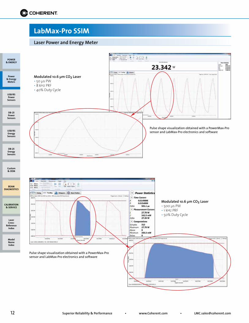
Modulated 10.6 µm CO2 Laser• 50 µs PW• 8 kHz PRF• 40% Duty Cycle
Pulse shape visualization obtained with a PowerMax-Pro sensor and LabMax-Pro electronics and software
Modulated 10.6 µm CO2 Laser• 500 µs PW• 1 kHz PRF• 50% Duty Cycle
Pulse shape visualization obtained with a PowerMax-Pro sensor and LabMax-Pro electronics and software
13• Toll Free: (800) 343-4912 • Tel: (408) 764-4042 • Fax: (503) 454-5727
LabMax-Pro SSIMLaser Power and Energy Meter
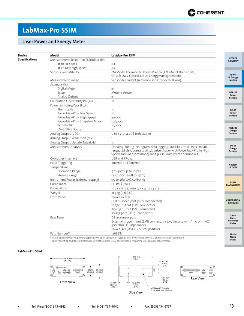
Model LabMax-Pro SSIMMeasurement Resolution (%)(full-scale) at 10 Hz speed 0.1 at 20 KHz high speed 0.2Sensor Compatibility PM Model Thermopile; PowerMax-Pro; LM Model Thermopile, OP-2 & LM-2 Optical, DB-25 EnergyMax pyroelectricMeasurement Range Sensor dependent (reference sensor specifications)Accuracy (%) Digital Meter ±1 System Meter + sensor Analog Output ±1Calibration Uncertainty (%)(k=2) ±1Power Sampling Rate (Hz) Thermopile 10 PowerMax-Pro - Low Speed 10 PowerMax-Pro - High Speed 20,000 PowerMax-Pro - Snapshot Mode 625,000 Pyroelectric 10,000 LM-2/OP-2 Optical 10Analog Output (VDC) 0 to 1, 2, or 4.096 (selectable)Analog Output Resolution (mV) 1Analog Output Update Rate (kHz) 19Measurement Analysis Trending, tuning, histogram, data logging, statistics (min., max., mean, range, std. dev., dose, stability), pulse shape (with PowerMax-Pro in High Speed and Snapshot mode), long pulse Joules with thermopilesComputer Interface USB and RS-232Pulse Triggering Internal and ExternalTemperature Operating Range 5 to 40°C (41 to 104°F) Storage Range -20 to 70°C (-68 to 158°F)Instrument Power (external supply) 90 to 260 VAC, 50/60 HzCompliance CE, RoHS, WEEEDimensions 105 x 105 x 32 mm (4.1 x 4.1 x 1.3 in.)Weight 0.3 kg (0.6 lbs.)Front Panel Power switch USB hi-speed port (mini B connector) Trigger output (SMB connector) Analog output (SMB connector) RS-232 port (DB-9F connector)Rear Panel DB-25 sensor port External trigger input (SMB connector, 3 to 5 Vin, 2 to 10 mA, 50 ohm AC, 300 ohm DC impedance) Power jack (12VDC - center positive)Part Number1,2 1268881
Device Specifications
1 Meter supplied with AC power adapter, power cord, USB cable, trigger cable, software and driver CD, and certificate of calibration. 2 OEM mounting and stacking hardware kit (Part Number 1268401) is available for purchase as an optional accessory.
POWER & ENERGY
Custom & OEM
BEAM DIAGNOSTICS
CALIBRATION & SERVICE
Power & Energy
Meters
Laser Cross-
Reference Index
Model Name Index
DB-25Energy Sensors
USB/RSEnergy Sensors
DB-25Power
Sensors
USB/RSPower
Sensors
4X No.4-40 Threads2 PL, Near and Far Side
104.9 mm(4.1 in.)
32 mm(1.3 in.)
34.5 mm(1.4 in.)
105.6 mm(4.2 in.)
31 mm(1.2 in.)
2 PL
43.5 mm(1.7 in.)
2 PL
9.2 mm(0.4 in.)
2 PL
13.7 mm(0.5 in.)
2 PLFront View
Side View
Rear View
LabMax-Pro SSIM
14 Superior Reliability & Performance • www.Coherent.com • [email protected]
LM-45 HTD sensor with beam position
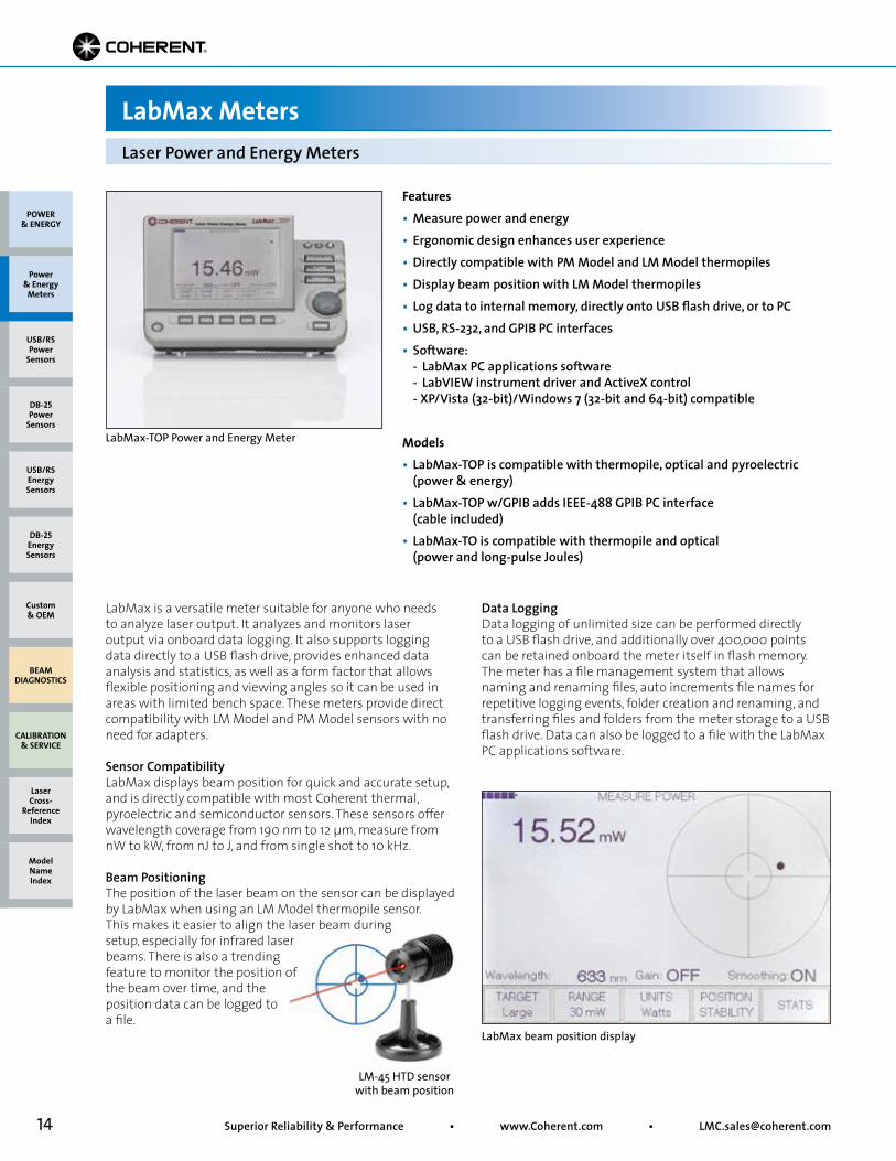
Features• Measure power and energy• Ergonomic design enhances user experience• Directly compatible with PM Model and LM Model thermopiles• Display beam position with LM Model thermopiles• Log data to internal memory, directly onto USB flash drive, or to PC• USB, RS-232, and GPIB PC interfaces• Software: - LabMax PC applications software - LabVIEW instrument driver and ActiveX control - XP/Vista (32-bit)/Windows 7 (32-bit and 64-bit) compatible
Models• LabMax-TOP is compatible with thermopile, optical and pyroelectric (power & energy)• LabMax-TOP w/GPIB adds IEEE-488 GPIB PC interface (cable included)• LabMax-TO is compatible with thermopile and optical (power and long-pulse Joules)
LabMax is a versatile meter suitable for anyone who needs to analyze laser output. It analyzes and monitors laser output via onboard data logging. It also supports logging data directly to a USB flash drive, provides enhanced data analysis and statistics, as well as a form factor that allows flexible positioning and viewing angles so it can be used in areas with limited bench space. These meters provide direct compatibility with LM Model and PM Model sensors with no need for adapters.
Sensor CompatibilityLabMax displays beam position for quick and accurate setup, and is directly compatible with most Coherent thermal, pyroelectric and semiconductor sensors. These sensors offer wavelength coverage from 190 nm to 12 µm, measure from nW to kW, from nJ to J, and from single shot to 10 kHz.
Beam PositioningThe position of the laser beam on the sensor can be displayed by LabMax when using an LM Model thermopile sensor. This makes it easier to align the laser beam during setup, especially for infrared laser beams. There is also a trending feature to monitor the position of the beam over time, and the position data can be logged to a file.
Laser Power and Energy Meters
LabMax Meters
Data LoggingData logging of unlimited size can be performed directly to a USB flash drive, and additionally over 400,000 points can be retained onboard the meter itself in flash memory. The meter has a file management system that allows naming and renaming files, auto increments file names for repetitive logging events, folder creation and renaming, and transferring files and folders from the meter storage to a USB flash drive. Data can also be logged to a file with the LabMax PC applications software.
LabMax beam position display
LabMax-TOP Power and Energy Meter
POWER & ENERGY
Custom & OEM
BEAM DIAGNOSTICS
CALIBRATION & SERVICE
Power & Energy
Meters
Laser Cross-
Reference Index
Model Name Index
DB-25Energy Sensors
USB/RSEnergy Sensors
DB-25Power
Sensors
USB/RSPower
Sensors
15• Toll Free: (800) 343-4912 • Tel: (408) 764-4042 • Fax: (503) 454-5727
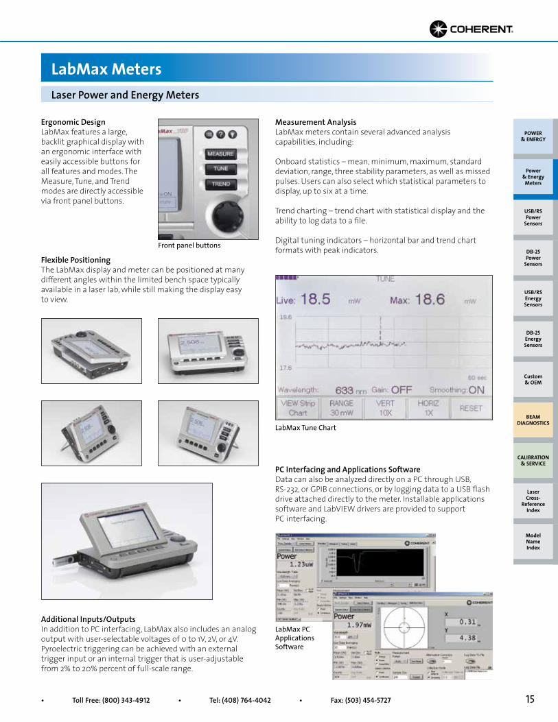
Ergonomic DesignLabMax features a large, backlit graphical display with an ergonomic interface with easily accessible buttons for all features and modes. The Measure, Tune, and Trend modes are directly accessible via front panel buttons.
Additional Inputs/OutputsIn addition to PC interfacing, LabMax also includes an analog output with user-selectable voltages of 0 to 1V, 2V, or 4V. Pyroelectric triggering can be achieved with an external trigger input or an internal trigger that is user-adjustable from 2% to 20% percent of full-scale range.
PC Interfacing and Applications SoftwareData can also be analyzed directly on a PC through USB, RS-232, or GPIB connections, or by logging data to a USB flash drive attached directly to the meter. Installable applications software and LabVIEW drivers are provided to support PC interfacing.
Front panel buttons
LabMax PC Applications Software
Measurement AnalysisLabMax meters contain several advanced analysis capabilities, including:
Onboard statistics – mean, minimum, maximum, standard deviation, range, three stability parameters, as well as missed pulses. Users can also select which statistical parameters to display, up to six at a time.
Trend charting – trend chart with statistical display and the ability to log data to a file.
Digital tuning indicators – horizontal bar and trend chart formats with peak indicators.
Flexible PositioningThe LabMax display and meter can be positioned at many different angles within the limited bench space typically available in a laser lab, while still making the display easy to view.
Laser Power and Energy Meters
LabMax Meters
LabMax Tune Chart
POWER & ENERGY
Custom & OEM
BEAM DIAGNOSTICS
CALIBRATION & SERVICE
Power & Energy
Meters
Laser Cross-
Reference Index
Model Name Index
DB-25Energy Sensors
USB/RSEnergy Sensors
DB-25Power
Sensors
USB/RSPower
Sensors
16 Superior Reliability & Performance • www.Coherent.com • [email protected]
Laser Power and Energy Meters
LabMax Meters
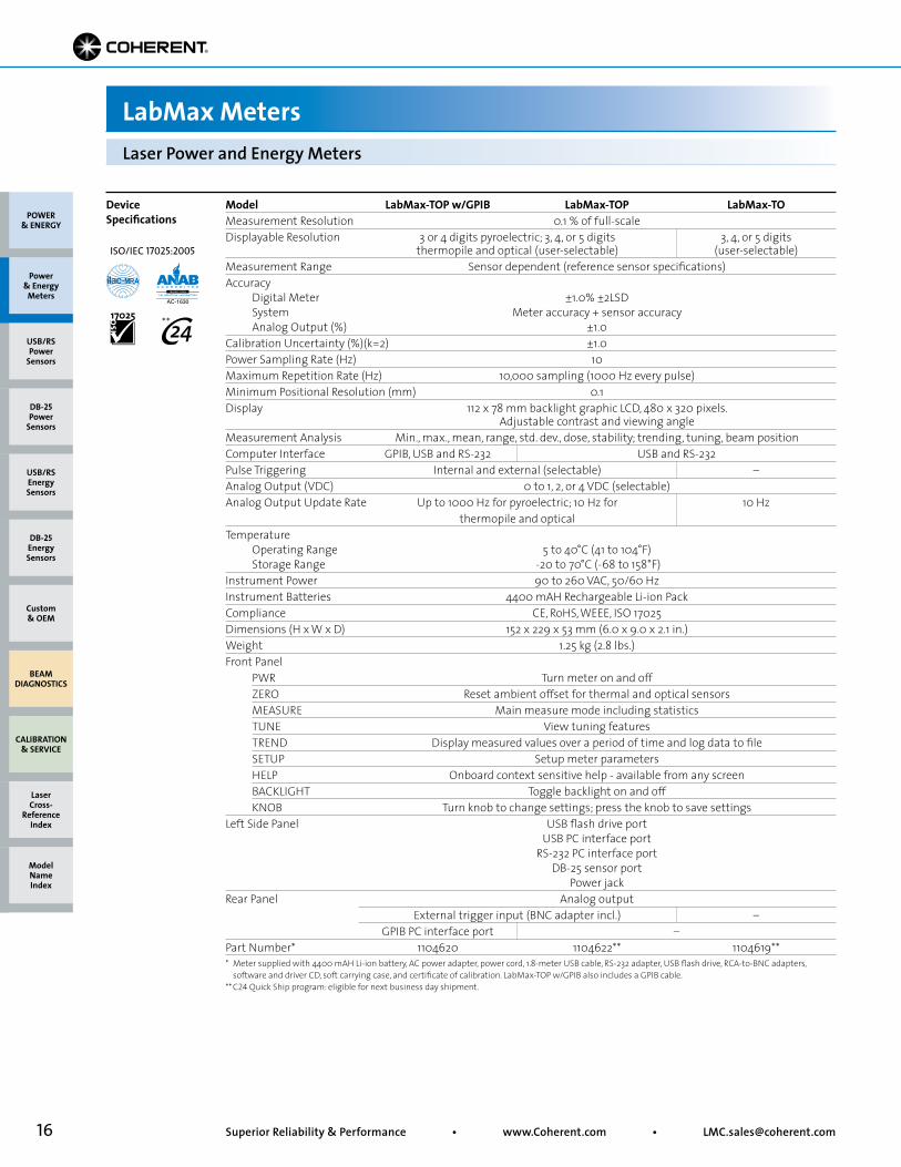
Model LabMax-TOP w/GPIB LabMax-TOP LabMax-TOMeasurement Resolution 0.1 % of full-scaleDisplayable Resolution 3 or 4 digits pyroelectric; 3, 4, or 5 digits 3, 4, or 5 digits thermopile and optical (user-selectable) (user-selectable)Measurement Range Sensor dependent (reference sensor specifications)Accuracy Digital Meter ±1.0% ±2LSD System Meter accuracy + sensor accuracy Analog Output (%) ±1.0Calibration Uncertainty (%)(k=2) ±1.0Power Sampling Rate (Hz) 10Maximum Repetition Rate (Hz) 10,000 sampling (1000 Hz every pulse)Minimum Positional Resolution (mm) 0.1 Display 112 x 78 mm backlight graphic LCD, 480 x 320 pixels. Adjustable contrast and viewing angleMeasurement Analysis Min., max., mean, range, std. dev., dose, stability; trending, tuning, beam position Computer Interface GPIB, USB and RS-232 USB and RS-232 Pulse Triggering Internal and external (selectable) –Analog Output (VDC) 0 to 1, 2, or 4 VDC (selectable)Analog Output Update Rate Up to 1000 Hz for pyroelectric; 10 Hz for 10 Hz thermopile and optical Temperature Operating Range 5 to 40°C (41 to 104°F) Storage Range -20 to 70°C (-68 to 158°F)Instrument Power 90 to 260 VAC, 50/60 HzInstrument Batteries 4400 mAH Rechargeable Li-ion PackCompliance CE, RoHS, WEEE, ISO 17025Dimensions (H x W x D) 152 x 229 x 53 mm (6.0 x 9.0 x 2.1 in.)Weight 1.25 kg (2.8 lbs.)Front Panel PWR Turn meter on and off ZERO Reset ambient offset for thermal and optical sensors MEASURE Main measure mode including statistics TUNE View tuning features TREND Display measured values over a period of time and log data to file SETUP Setup meter parameters HELP Onboard context sensitive help - available from any screen BACKLIGHT Toggle backlight on and off KNOB Turn knob to change settings; press the knob to save settingsLeft Side Panel USB flash drive port USB PC interface port RS-232 PC interface port DB-25 sensor port Power jackRear Panel Analog output External trigger input (BNC adapter incl.) – GPIB PC interface port –Part Number* 1104620 1104622** 1104619**
Device Specifications
* Meter supplied with 4400 mAH Li-ion battery, AC power adapter, power cord, 1.8-meter USB cable, RS-232 adapter, USB flash drive, RCA-to-BNC adapters, software and driver CD, soft carrying case, and certificate of calibration. LabMax-TOP w/GPIB also includes a GPIB cable.** C24 Quick Ship program: eligible for next business day shipment.
POWER & ENERGY
Custom & OEM
BEAM DIAGNOSTICS
CALIBRATION & SERVICE
Power & Energy
Meters
Laser Cross-
Reference Index
Model Name Index
DB-25Energy Sensors
USB/RSEnergy Sensors
DB-25Power
Sensors
USB/RSPower
Sensors
ISO/IEC 17025:2005
**
17• Toll Free: (800) 343-4912 • Tel: (408) 764-4042 • Fax: (503) 454-5727
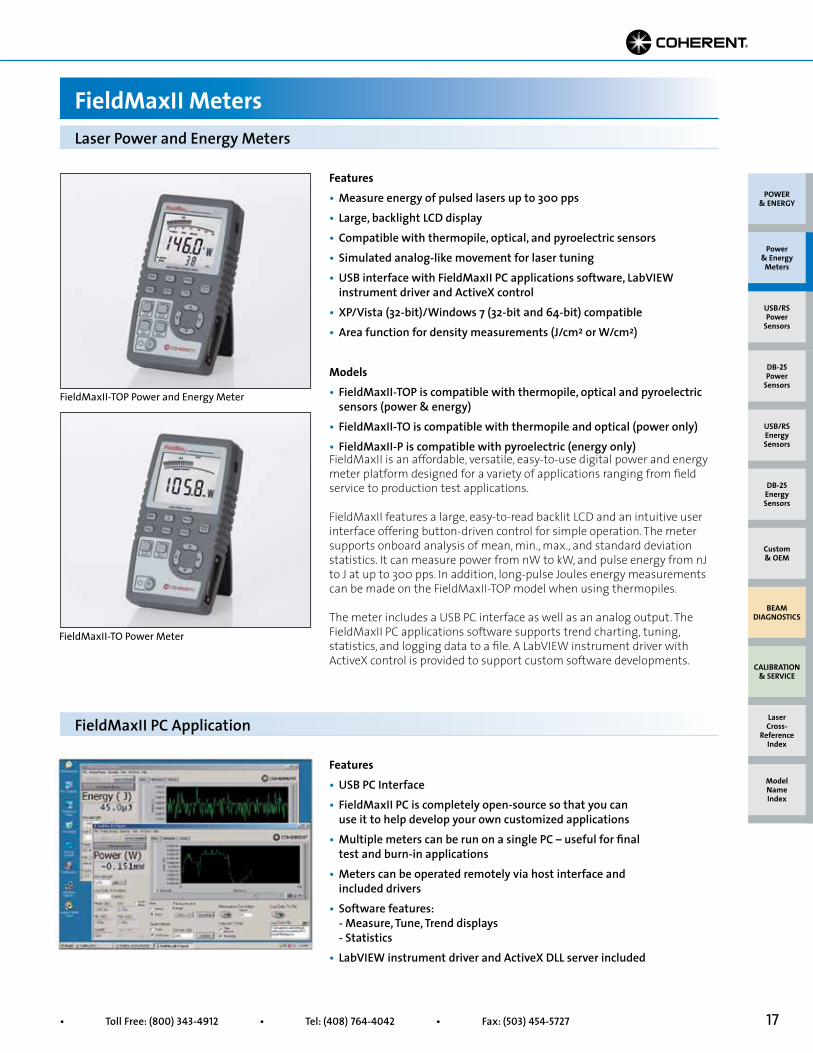
FieldMaxII-TOP Power and Energy Meter
FieldMaxII-TO Power Meter
FieldMaxII is an affordable, versatile, easy-to-use digital power and energy meter platform designed for a variety of applications ranging from field service to production test applications.
FieldMaxII features a large, easy-to-read backlit LCD and an intuitive user interface offering button-driven control for simple operation. The meter supports onboard analysis of mean, min., max., and standard deviation statistics. It can measure power from nW to kW, and pulse energy from nJ to J at up to 300 pps. In addition, long-pulse Joules energy measurements can be made on the FieldMaxII-TOP model when using thermopiles.
The meter includes a USB PC interface as well as an analog output. The FieldMaxII PC applications software supports trend charting, tuning, statistics, and logging data to a file. A LabVIEW instrument driver with ActiveX control is provided to support custom software developments.
Features• USB PC Interface• FieldMaxII PC is completely open-source so that you can use it to help develop your own customized applications• Multiple meters can be run on a single PC – useful for final test and burn-in applications• Meters can be operated remotely via host interface and included drivers• Software features: - Measure, Tune, Trend displays - Statistics• LabVIEW instrument driver and ActiveX DLL server included
Features• Measure energy of pulsed lasers up to 300 pps• Large, backlight LCD display• Compatible with thermopile, optical, and pyroelectric sensors• Simulated analog-like movement for laser tuning• USB interface with FieldMaxII PC applications software, LabVIEW instrument driver and ActiveX control• XP/Vista (32-bit)/Windows 7 (32-bit and 64-bit) compatible• Area function for density measurements (J/cm2 or W/cm2)
Models• FieldMaxII-TOP is compatible with thermopile, optical and pyroelectric sensors (power & energy)• FieldMaxII-TO is compatible with thermopile and optical (power only)• FieldMaxII-P is compatible with pyroelectric (energy only)
FieldMaxII PC Application
Laser Power and Energy Meters
FieldMaxII Meters
POWER & ENERGY
Custom & OEM
BEAM DIAGNOSTICS
CALIBRATION & SERVICE
Power & Energy
Meters
Laser Cross-
Reference Index
Model Name Index
DB-25Energy Sensors
USB/RSEnergy Sensors
DB-25Power
Sensors
USB/RSPower
Sensors
18 Superior Reliability & Performance • www.Coherent.com • [email protected]
Laser Power and Energy Meters
FieldMaxII Meters
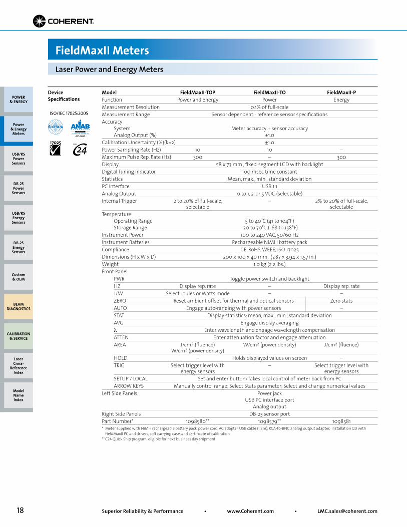
Model FieldMaxII-TOP FieldMaxII-TO FieldMaxII-PFunction Power and energy Power EnergyMeasurement Resolution 0.1% of full-scaleMeasurement Range Sensor dependent - reference sensor specificationsAccuracy System Meter accuracy + sensor accuracy Analog Output (%) ±1.0Calibration Uncertainty (%)(k=2) ±1.0Power Sampling Rate (Hz) 10 10 –Maximum Pulse Rep. Rate (Hz) 300 – 300Display 58 x 73 mm , fixed-segment LCD with backlightDigital Tuning Indicator 100 msec time constantStatistics Mean, max., min., standard deviationPC Interface USB 1.1 Analog Output 0 to 1, 2, or 5 VDC (selectable)Internal Trigger 2 to 20% of full-scale, – 2% to 20% of full-scale, selectable selectableTemperature Operating Range 5 to 40°C (41 to 104°F) Storage Range -20 to 70°C (-68 to 158°F)Instrument Power 100 to 240 VAC, 50/60 HzInstrument Batteries Rechargeable NiMH battery packCompliance CE, RoHS, WEEE, ISO 17025Dimensions (H x W x D) 200 x 100 x 40 mm, (7.87 x 3.94 x 1.57 in.)Weight 1.0 kg (2.2 lbs.)Front Panel PWR Toggle power switch and backlight HZ Display rep. rate – Display rep. rate J/W Select Joules or Watts mode – – ZERO Reset ambient offset for thermal and optical sensors Zero stats AUTO Engage auto-ranging with power sensors – STAT Display statistics: mean, max., min., standard deviation AVG Engage display averaging λ Enter wavelength and engage wavelength compensation ATTEN Enter attenuation factor and engage attenuation AREA J/cm2 (fluence) W/cm2 (power density) J/cm2 (fluence) W/cm2 (power density) HOLD – Holds displayed values on screen – TRIG Select trigger level with – Select trigger level with energy sensors energy sensors SETUP / LOCAL Set and enter button/Takes local control of meter back from PC ARROW KEYS Manually control range; Select Stats parameter; Select and change numerical valuesLeft Side Panels Power jack USB PC interface port Analog outputRight Side Panels DB-25 sensor portPart Number* 1098580** 1098579** 1098581* Meter supplied with NiMH rechargeable battery pack, power cord, AC adapter, USB cable (1.8m), RCA-to-BNC analog output adapter, installation CD with FieldMaxII PC and drivers, soft carrying case, and certificate of calibration. ** C24 Quick Ship program: eligible for next business day shipment.
POWER & ENERGY
Custom & OEM
BEAM DIAGNOSTICS
CALIBRATION & SERVICE
Power & Energy
Meters
Laser Cross-
Reference Index
Model Name Index
DB-25Energy Sensors
USB/RSEnergy Sensors
DB-25Power
Sensors
USB/RSPower
Sensors
Device Specifications
ISO/IEC 17025:2005
**
19• Toll Free: (800) 343-4912 • Tel: (408) 764-4042 • Fax: (503) 454-5727
Model FieldMatePower Resolution 0.1% of full-scale for all ranges in the 10s scale 0.3% of full-scale for all ranges in the 3s scaleMeasurement Range Sensor dependent (reference sensor specifications)Accuracy System Meter accuracy + sensor accuracy Analog Meter (%) ±3.0 Analog Output (%) ±1.0Calibration Uncertainty (%)(k=2) ±1.0Power Sampling Rate 20 Hz (thermopile and optical)Display 26 x 89 mm, custom fixed-segment LCDAnalog Needle Scale 0 to 10 (100 divisions), 0 to 3 (60 divisions) Response 80 ms time constantAnalog Output Voltage 0 to 2 VDC Update Rate 20 times/sec.Temperature Operating Range 5 to 40°C (41 to 104°F) Storage Range -20 to 70°C (-68 to 158°F)Instrument Power 100 to 240 VAC, 50/60 HzInstrument Batteries Two 9V alkaline batteriesCompliance CE, RoHS, WEEE, ISO 17025Dimensions (H x W x D) 193 x 117 x 46 mm, (7.6 x 4.6 x 1.8 in.)Weight 0.8 kg (1.8 lbs.)Front Panel PWR Toggle power ZERO Ambient offset AUTO Engage auto-ranging λ Enter wavelength compensation ARROW KEYS Manually control range; select and change numerical values Left Side Panel Power jack Analog output DB-25 sensor port Part Number* 1098297**
Device Specifications
* Meter supplied with two alkaline 9V batteries, power cord, AC power adapter, RCA-to-BNC analog output adapter, and certificate of calibration.** C24 Quick Ship program: eligible for next business day shipment.
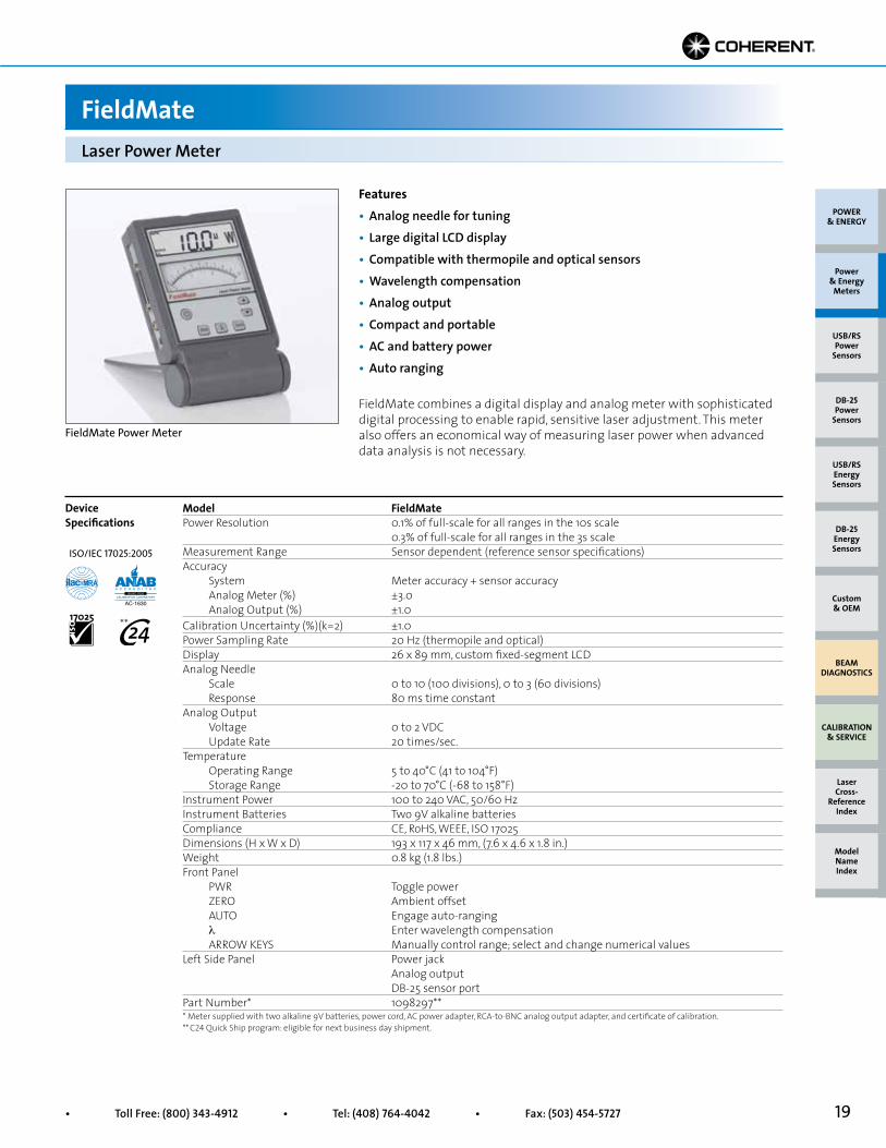
Features• Analog needle for tuning• Large digital LCD display• Compatible with thermopile and optical sensors• Wavelength compensation• Analog output• Compact and portable• AC and battery power• Auto ranging
Laser Power Meter
FieldMate
FieldMate combines a digital display and analog meter with sophisticated digital processing to enable rapid, sensitive laser adjustment. This meter also offers an economical way of measuring laser power when advanced data analysis is not necessary.
FieldMate Power Meter
POWER & ENERGY
Custom & OEM
BEAM DIAGNOSTICS
CALIBRATION & SERVICE
Power & Energy
Meters
Laser Cross-
Reference Index
Model Name Index
DB-25Energy Sensors
USB/RSEnergy Sensors
DB-25Power
Sensors
USB/RSPower
Sensors
ISO/IEC 17025:2005
**
20 Superior Reliability & Performance • www.Coherent.com • [email protected]
Laser Power Meter
LaserCheck
Model LaserCheckActive Area Diameter (mm) 8Spectral Range (nm) 400 to 1064Accuracy (%) ±5Measurement Range1 without Attenuator 10 µW to 10 mW with Attenuator 1 mW to 1WDisplay Power Ranges 9.99 µW to 999 mW Calibration Uncertainty (%)(k=2) 5Minimum Power Resolution (µW) 0.01Maximum Peak Power Density without Attenuator 0.5 W/cm2
with Attenuator 30 W/cm2
Display 3-digit LCD display with power unit indicatorCompliance CE, WEEE, RoHSDimensions (H x W x D) 168 x 24 x 20 mm (6.6 x 0.9 x 0.7 in.)Weight 44 g (0.09 lbs.)Part Number (RoHS) 1098293**
Device Specifications
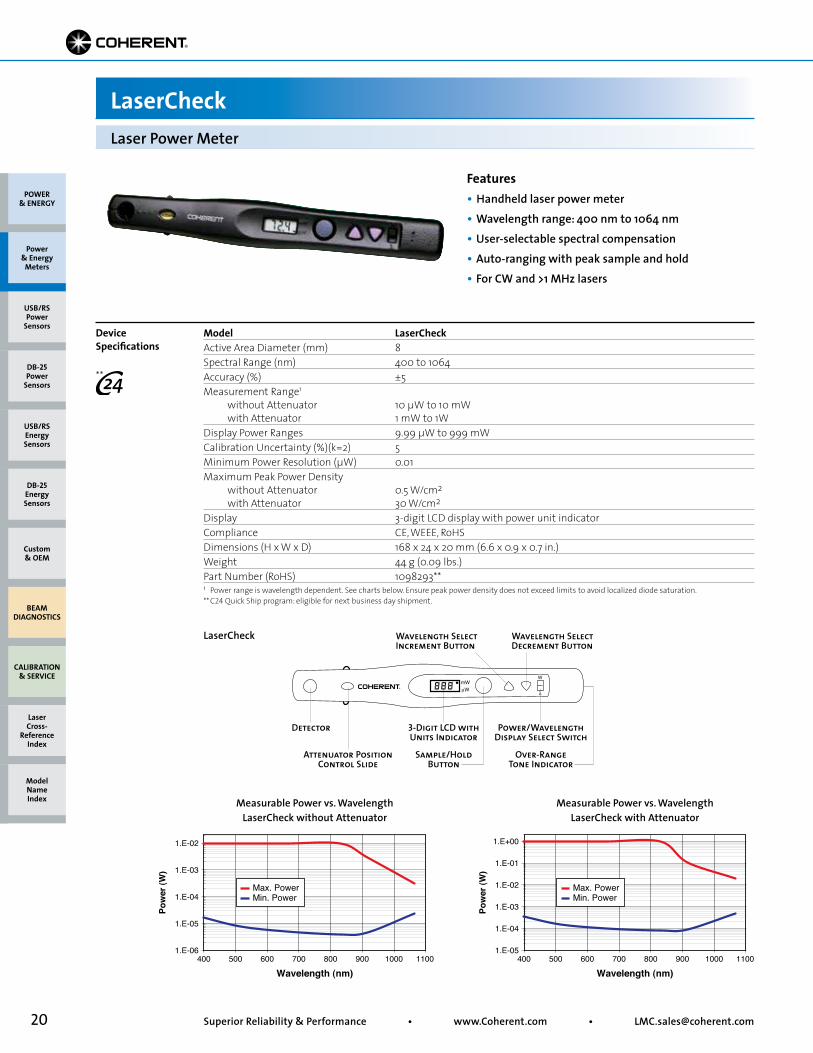
Features• Handheld laser power meter• Wavelength range: 400 nm to 1064 nm• User-selectable spectral compensation• Auto-ranging with peak sample and hold• For CW and >1 MHz lasers
Wavelength (nm)
Pow
er (W
)
1.E-06400
1.E-05
1.E-04
1.E-03
1.E-02
500 600 700 800 900 1000 1100
Min. PowerMax. Power
Wavelength (nm)
Pow
er (W
)
1.E-05400
1.E-04
1.E-03
1.E-02
1.E-01
1.E+00
500 600 700 800 900 1000 1100
Min. PowerMax. Power
1 Power range is wavelength dependent. See charts below. Ensure peak power density does not exceed limits to avoid localized diode saturation. ** C24 Quick Ship program: eligible for next business day shipment.
Detector 3-Digit LCD with Units Indicator
Attenuator PositionControl Slide
Sample/Hold Button
Wavelength SelectIncrement Button
Wavelength Select Decrement Button
Power/WavelengthDisplay Select Switch
Over-RangeTone Indicator
168 mm(6.6 in.)
20 mm(0.79 in.)
24 mm(0.95 in.)
Ø8 mm (0.31 in.)
Side View
Front View
LaserCheck
POWER & ENERGY
Custom & OEM
BEAM DIAGNOSTICS
CALIBRATION & SERVICE
Power & Energy
Meters
Laser Cross-
Reference Index
Model Name Index
DB-25Energy Sensors
USB/RSEnergy Sensors
DB-25Power
Sensors
USB/RSPower
Sensors
Measurable Power vs. WavelengthLaserCheck without Attenuator
Measurable Power vs. WavelengthLaserCheck with Attenuator
**
21• Toll Free: (800) 343-4912 • Tel: (408) 764-4042 • Fax: (503) 454-5727
POWER & ENERGY
Custom & OEM
BEAM DIAGNOSTICS
CALIBRATION & SERVICE
Power & Energy
Meters
Laser Cross-
Reference Index
Model Name Index
DB-25Energy Sensors
USB/RSEnergy Sensors
DB-25Power
Sensors
USB/RSPower
Sensors
Soft Carrying Case
Part Number Description1212401 Soft Carrying Case for FieldMate1122466 Soft Carrying Case for FieldMaxII, LabMax
Rechargeable Batteries
Part Number Description1092395 7.2V 750 mAh NiMH Rechargeable Battery Pack for FieldMaxII1110945 7.4V 5100 mAh Li-ion Rechargeable Battery Pack for LabMax
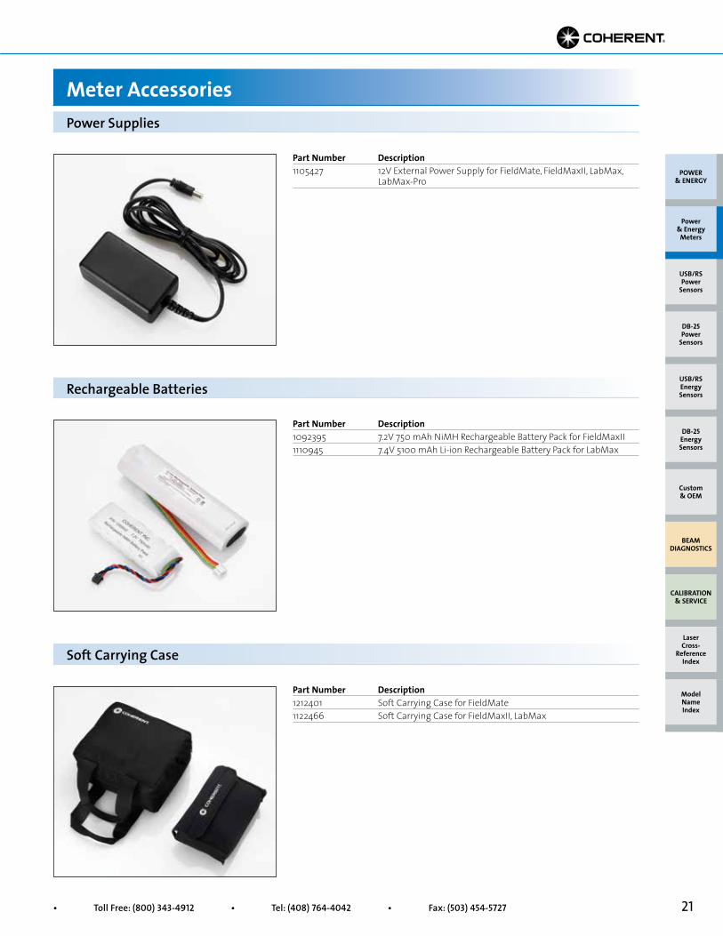
Part Number Description1105427 12V External Power Supply for FieldMate, FieldMaxII, LabMax, LabMax-Pro
Power Supplies
Meter Accessories
22 Superior Reliability & Performance • www.Coherent.com • [email protected]
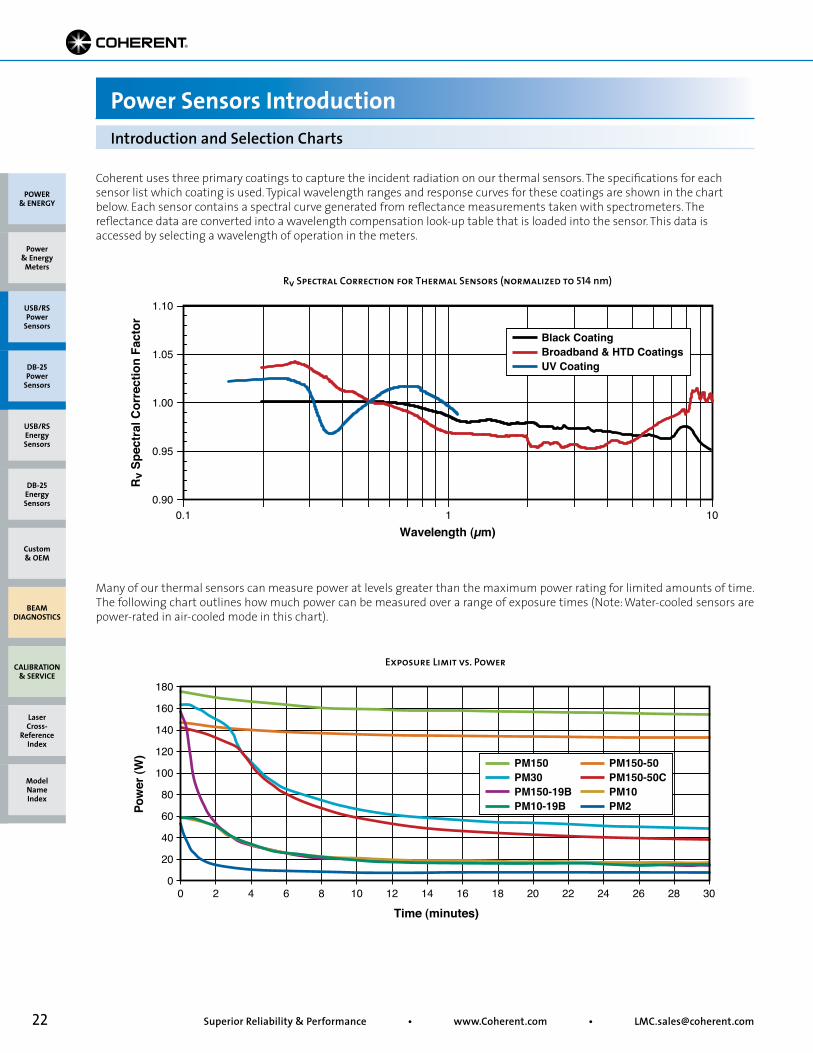
Coherent uses three primary coatings to capture the incident radiation on our thermal sensors. The specifications for each sensor list which coating is used. Typical wavelength ranges and response curves for these coatings are shown in the chart below. Each sensor contains a spectral curve generated from reflectance measurements taken with spectrometers. The reflectance data are converted into a wavelength compensation look-up table that is loaded into the sensor. This data is accessed by selecting a wavelength of operation in the meters.
Many of our thermal sensors can measure power at levels greater than the maximum power rating for limited amounts of time. The following chart outlines how much power can be measured over a range of exposure times (Note: Water-cooled sensors are power-rated in air-cooled mode in this chart).
Introduction and Selection Charts
Power Sensors Introduction
0.90
0.95
1.00
1.05
1.10
Rv Spectral Correction for Thermal Sensors (normalized to 514 nm)
0.1 1 10Wavelength (µm)
Rv
Spec
tral
Cor
rect
ion
Fact
or
Black CoatingBroadband & HTD CoatingsUV Coating
Exposure Limit vs. Power
0 2 4 6 8 10 12 14 16 18 20 22 24 26 28 300
20
40
60
80
100
120
140
160
180
Time (minutes)
Pow
er (W
)
PM150PM30PM150-19BPM10-19B
PM150-50PM150-50CPM10PM2
POWER & ENERGY
Custom & OEM
BEAM DIAGNOSTICS
CALIBRATION & SERVICE
Power & Energy
Meters
Laser Cross-
Reference Index
Model Name Index
DB-25Energy Sensors
USB/RSEnergy Sensors
DB-25Power
Sensors
USB/RSPower
Sensors

23• Toll Free: (800) 343-4912 • Tel: (408) 764-4042 • Fax: (503) 454-5727
PM10-19C, PM150-50C and PM150-50XC
Long-Pulse Energy Measurement with a Thermopile
Power Sensors Introduction
Thermopile sensors are most commonly used for average power measurements on pulsed and CW lasers. Thermopiles are also capable of integrating long pulse widths. This allows the thermopile to measure the energy of single pulses between 1 millisecond and 10 seconds in length, and with energies from millijoules to hundreds of Joules. Long-pulse measurement is only possible when the thermopiles are used in conjunction with LabMax-TOP, LabMax-TO, or FieldMaxII-TOP meters, or when using a PowerMax-USB/RS sensor.
This ability to integrate relatively long laser pulses with a thermopile is necessary when the laser pulse width exceeds the maximum pulse width rating of pyroelectric sensors. Pyroelectric sensors are typically limited to maximum pulse widths in the millisecond range. When the pulse width exceeds milliseconds, a thermopile is a good solution.
A good “rule of thumb” for using a thermopile for this type of measurement is to compare the maximum pulse energy you need to measure with the maximum power rating of a sensor (maximum power ratings can be found in the Power Sensor Summary Specifications on pages 51 to 52 or in the detailed product specifications contained on each product page).
Common applications for this type of measurement are in the medical field, especially skin resurfacing and hair removal, and in material processing applications such as laser welding. These laser systems often utilize high-energy diode lasers that have large beam sizes and relatively long pulses. A detector like the PM150-50C is ideal for these measurements. It features a large 50 mm aperture size, can handle pulse energies up to 150J, and can be used air-cooled for single pulse energy measurements (a PM150-50C will normally need to be water-cooled for continuous power measurements).
Using a LabMax power/energy meter, or a PowerMax-USB/RS sensor, expands the range of long-pulse Joule measurements down into the low millijoule level when used with thermopiles such as the PS10, PS10Q, PS19, and PS19Q sensors.
Long-pulse measurements are limited to single pulses in order to achieve the most accurate measurements.
Application Example 1Laser Pulse Width 50 msMaximum Energy 10JSolution Choose a PM10
Application Example 2Laser Pulse Width 300 msMaximum Energy 80JSolution Choose a PM150 or PM150-50C** Specific sensor choice depends upon aperture and mechanical constraints.
POWER & ENERGY
Custom & OEM
BEAM DIAGNOSTICS
CALIBRATION & SERVICE
Power & Energy
Meters
Laser Cross-
Reference Index
Model Name Index
DB-25Energy Sensors
USB/RSEnergy Sensors
DB-25Power
Sensors
USB/RSPower
Sensors
24 Superior Reliability & Performance • www.Coherent.com • [email protected]
PowerMax-Pro SensorsLaser Power Sensors
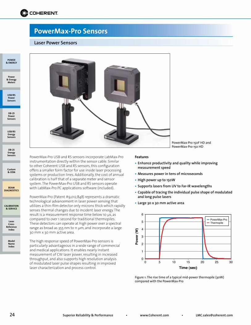
Figure 1: The rise time of a typical mid-power thermopile (30W) compared with the PowerMax-Pro
POWER & ENERGY
Custom & OEM
BEAM DIAGNOSTICS
CALIBRATION & SERVICE
Power & Energy
Meters
Laser Cross-
Reference Index
Model Name Index
DB-25Energy Sensors
USB/RSEnergy Sensors
DB-25Power
Sensors
USB/RSPower
Sensors
PowerMax-Pro USB and RS sensors incorporate LabMax-Pro instrumentation directly within the sensor cable. Similar to other Coherent USB and RS sensors, this configuration offers a smaller form factor for use inside laser processing systems or production lines. Additionally, the cost of annual calibration is half that of a separate meter and sensor system. The PowerMax-Pro USB and RS sensors operate with LabMax-Pro PC applications software (included).
PowerMax-Pro (Patent #9,012,848) represents a dramatic technological advancement in laser power sensing that utilizes a thin-film detector only microns thick which rapidly senses thermal changes due to incident laser energy. The result is a measurement response time below 10 µs, as compared to over 1 second for traditional thermopiles. These detectors can operate at high power over a spectral range as broad as 355 nm to 11 µm, and incorporate a large 30 mm x 30 mm active area.
The high response speed of PowerMax-Pro sensors is particularly advantageous in a wide range of commercial and medical applications. It enables nearly instant measurement of CW laser power, resulting in increased throughput, and also supports high resolution analysis of modulated laser pulse shapes resulting in improved laser characterization and process control.
Features• Enhance productivity and quality while improving measurement speed• Measures power in tens of microseconds• High power up to 150W• Supports lasers from UV to Far-IR wavelengths• Capable of tracing the individual pulse shape of modulated and long pulse lasers• Large 30 x 30 mm active area
PowerMax-Pro 150F HD and PowerMax-Pro 150 HD
Pow
er (W
)
0
1
2
3
4
5
6
0
Time (sec)5 10 15 20 25 30
PowerMax-ProThermopile
25• Toll Free: (800) 343-4912 • Tel: (408) 764-4042 • Fax: (503) 454-5727
PowerMax-Pro SensorsLaser Power Sensors
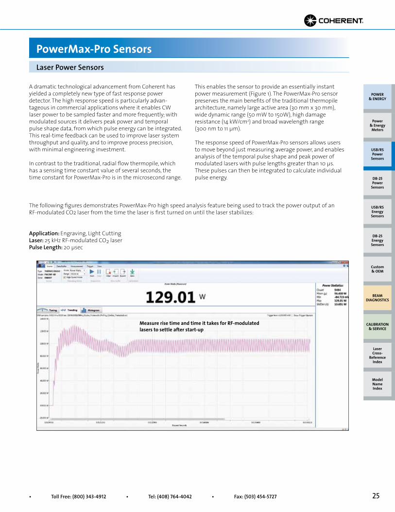
The following figures demonstrates PowerMax-Pro high speed analysis feature being used to track the power output of an RF-modulated CO2 laser from the time the laser is first turned on until the laser stabilizes:
POWER & ENERGY
Custom & OEM
BEAM DIAGNOSTICS
CALIBRATION & SERVICE
Power & Energy
Meters
Laser Cross-
Reference Index
Model Name Index
DB-25Energy Sensors
USB/RSEnergy Sensors
DB-25Power
Sensors
USB/RSPower
Sensors
A dramatic technological advancement from Coherent has yielded a completely new type of fast response power detector. The high response speed is particularly advan-tageous in commercial applications where it enables CW laser power to be sampled faster and more frequently; with modulated sources it delivers peak power and temporal pulse shape data, from which pulse energy can be integrated. This real-time feedback can be used to improve laser system throughput and quality, and to improve process precision, with minimal engineering investment.
In contrast to the traditional, radial flow thermopile, which has a sensing time constant value of several seconds, the time constant for PowerMax-Pro is in the microsecond range.
This enables the sensor to provide an essentially instant power measurement (Figure 1). The PowerMax-Pro sensor preserves the main benefits of the traditional thermopile architecture, namely large active area (30 mm x 30 mm), wide dynamic range (50 mW to 150W), high damage resistance (14 kW/cm2) and broad wavelength range (300 nm to 11 µm).
The response speed of PowerMax-Pro sensors allows users to move beyond just measuring average power, and enables analysis of the temporal pulse shape and peak power of modulated lasers with pulse lengths greater than 10 µs. These pulses can then be integrated to calculate individual pulse energy.
Application: Engraving, Light CuttingLaser: 25 kHz RF-modulated CO2 laserPulse Length: 20 µsec
Measure rise time and time it takes for RF-modulated lasers to settle after start-up
26 Superior Reliability & Performance • www.Coherent.com • [email protected]
POWER & ENERGY
Custom & OEM
BEAM DIAGNOSTICS
CALIBRATION & SERVICE
Power & Energy
Meters
Laser Cross-
Reference Index
Model Name Index
DB-25Energy Sensors
USB/RSEnergy Sensors
DB-25Power
Sensors
USB/RSPower
Sensors
PowerMax-Pro SensorsLaser Power Sensors
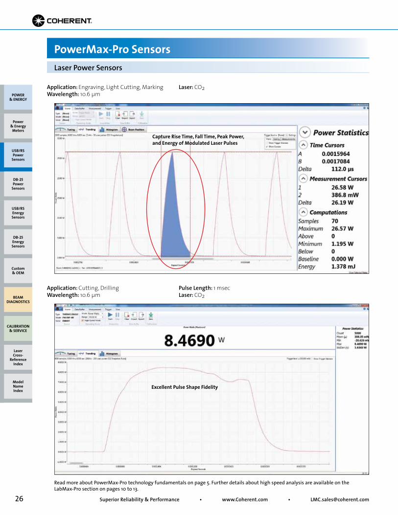
Read more about PowerMax-Pro technology fundamentals on page 5. Further details about high speed analysis are available on the LabMax-Pro section on pages 10 to 13.
Application: Engraving, Light Cutting, MarkingWavelength: 10.6 µm
Laser: CO2
Application: Cutting, DrillingWavelength: 10.6 µm
Pulse Length: 1 msec Laser: CO2
Capture Rise Time, Fall Time, Peak Power, and Energy of Modulated Laser Pulses
Excellent Pulse Shape Fidelity
27• Toll Free: (800) 343-4912 • Tel: (408) 764-4042 • Fax: (503) 454-5727
Device Specifications POWER
& ENERGY
Custom & OEM
BEAM DIAGNOSTICS
CALIBRATION & SERVICE
Power & Energy
Meters
Laser Cross-
Reference Index
Model Name Index
DB-25Energy Sensors
USB/RSEnergy Sensors
DB-25Power
Sensors
USB/RSPower
Sensors
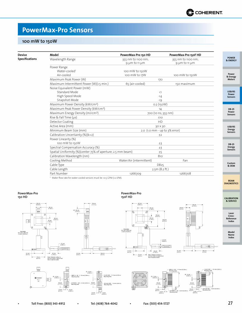
PowerMax-Pro Sensors100 mW to 150W
Model PowerMax-Pro 150 HD PowerMax-Pro 150F HDWavelength Range 355 nm to 1100 nm; 355 nm to 1100 nm; 9 µm to 11 µm 9 µm to 11 µmPower Range Water-cooled1 100 mW to 150W Air-cooled 100 mW to 17W 100 mW to 150WMaximum Peak Power (W) 170 Maximum Intermittent Power (W)(<5 min.) 65 (air-cooled) 150 maximumNoise Equivalent Power (mW) Standard Mode <1 High Speed Mode <4 Snapshot Mode <9Maximum Power Density (kW/cm2) 0.2 (150W)Maximum Peak Power Density (kW/cm2) 14Maximum Energy Density (mJ/cm2) 700 (10 ns; 355 nm)Rise & Fall Time (µs) ≤10Detector Coating HDActive Area (mm) 30 x 30Minimum Beam Size (mm) 2.0 (1.0 mm - up to 3% error)Calibration Uncertainty (%)(k=2) ±2Power Linearity (%) 100 mW to 150W ±3Spectral Compensation Accuracy (%) ±3Spatial Uniformity (%)(center 75% of aperture; 2.5 mm beam) ±5 Calibration Wavelength (nm) 810Cooling Method Water/Air (intermittent) FanCable Type DB25Cable Length 2.5m (8.2 ft.)Part Number 1266709 12667081 Water flow rate for water-cooled sensors must be >0.5 GPM (>2 LPM).
Adjustable191 mm to 260 mm(7.52 to 10.24 in.)
90 mm(3.54 in.)
90 mm(3.54 in.)
M6X1.0 - 6HMounting Hole
10 mm (0.39 in.) 1/4-20 UNCMounting Hole
10 mm (0.39 in.)
2X 6-32 UNCMounting Hole
6 mm (0.25 in.)2X M4X0.7 - 6HMounting Hole
6 mm (0.25 in.)
30 mm(1.17 in.)
30 mm(1.18 in.)
30 mm(1.18 in.)
21 mm(0.83 in.)
51 mm(2.0 in.)
109 mm(4.3 in.)
76 mm(3.0 in.)
Note: Detector surface is9.8 mm (0.38 in.) below frontface of aperture plate
44 mm(1.75 in.)
51 mm(2.0 in.)
26 mm(1.01 in.)
2X
6 mm(0.25 in.)
45 mm(1.77 in.)
45 mm(1.77 in.)
13 mm(0.5 in.)
6 mm(0.25 in.)
6 mm(0.25 in.)
13 mm(0.5 in.)
2X
6 mm(0.25 in.)
2X
PowerMax-Pro 150 HD
Adjustable191 mm to 260 mm(7.52 to 10.24 in.)
90 mm(3.54 in.)
6 mm(0.25 in.)
45 mm(1.77 in.)
45 mm(1.77 in.)
13 mm(0.5 in.)
13 mm(0.5 in.)
6 mm(0.25 in.)
6 mm(0.25 in.)
2X6 mm
(0.25 in.)
M6X1.0 - 6HMounting Hole
10 mm (0.39 in.)
2X
30 mm(1.18 in.)
90 mm(3.54 in.)
104 mm(4.09 in.)
21 mm(0.83 in.)
23 mm(0.9 in.)
95 mm(3.75 in.)
109 mm(4.3 in.)
51 mm(2.0 in.)
51 mm(2.0 in.)
76 mm(3.0 in.)
Note: Detector surface is9.8 mm (0.38 in.) below frontface of aperture plate
44 mm(1.75 in.)
30 mm(1.18 in.)
1/4-20 UNCMounting Hole
10 mm (0.39 in.)
2X 6-32 UNCMounting Hole
6 mm (0.25 in.)
2X M4X0.7 - 6HMounting Hole
6 mm (0.25 in.)
PowerMax-Pro 150F HD
Adjustable191 mm to 260 mm(7.52 to 10.24 in.)
90 mm(3.54 in.)
90 mm(3.54 in.)
M6X1.0 - 6HMounting Hole
10 mm (0.39 in.) 1/4-20 UNCMounting Hole
10 mm (0.39 in.)
2X 6-32 UNCMounting Hole
6 mm (0.25 in.)2X M4X0.7 - 6HMounting Hole
6 mm (0.25 in.)
30 mm(1.17 in.)
30 mm(1.18 in.)
30 mm(1.18 in.)
21 mm(0.83 in.)
51 mm(2.0 in.)
109 mm(4.3 in.)
76 mm(3.0 in.)
Note: Detector surface is9.8 mm (0.38 in.) below frontface of aperture plate
44 mm(1.75 in.)
51 mm(2.0 in.)
26 mm(1.01 in.)
2X
6 mm(0.25 in.)
45 mm(1.77 in.)
45 mm(1.77 in.)
13 mm(0.5 in.)
6 mm(0.25 in.)
6 mm(0.25 in.)
13 mm(0.5 in.)
2X
6 mm(0.25 in.)
2X
Adjustable191 mm to 260 mm(7.52 to 10.24 in.)
90 mm(3.54 in.)
6 mm(0.25 in.)
45 mm(1.77 in.)
45 mm(1.77 in.)
13 mm(0.5 in.)
13 mm(0.5 in.)
6 mm(0.25 in.)
6 mm(0.25 in.)
2X6 mm
(0.25 in.)
M6X1.0 - 6HMounting Hole
10 mm (0.39 in.)
2X
30 mm(1.18 in.)
90 mm(3.54 in.)
104 mm(4.09 in.)
21 mm(0.83 in.)
23 mm(0.9 in.)
95 mm(3.75 in.)
109 mm(4.3 in.)
51 mm(2.0 in.)
51 mm(2.0 in.)
76 mm(3.0 in.)
Note: Detector surface is9.8 mm (0.38 in.) below frontface of aperture plate
44 mm(1.75 in.)
30 mm(1.18 in.)
1/4-20 UNCMounting Hole
10 mm (0.39 in.)
2X 6-32 UNCMounting Hole
6 mm (0.25 in.)
2X M4X0.7 - 6HMounting Hole
6 mm (0.25 in.)
28 Superior Reliability & Performance • www.Coherent.com • [email protected]
PowerMax-Pro HP Sensors
POWER & ENERGY
Custom & OEM
BEAM DIAGNOSTICS
CALIBRATION & SERVICE
Power & Energy
Meters
Laser Cross-
Reference Index
Model Name Index
DB-25Energy Sensors
USB/RSEnergy Sensors
DB-25Power
Sensors
USB/RSPower
Sensors
Device Specifications
PowerMax-Pro HP
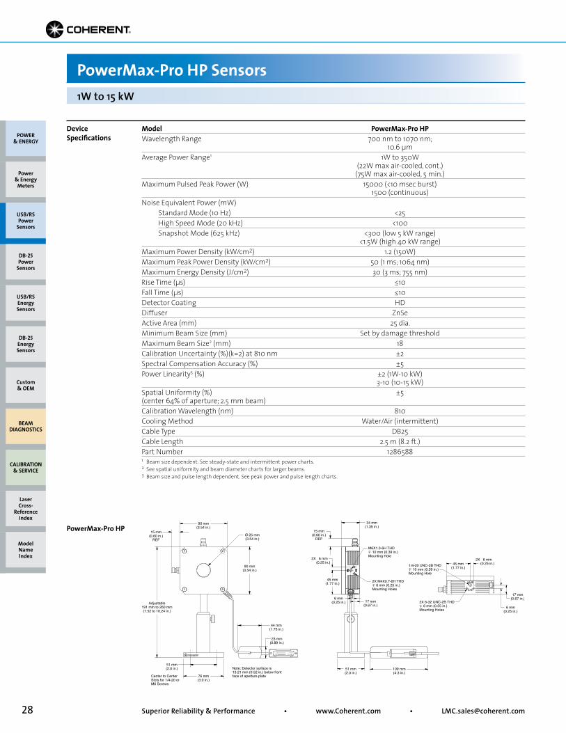
1W to 15 kW
Model PowerMax-Pro HPWavelength Range 700 nm to 1070 nm; 10.6 µmAverage Power Range1 1W to 350W (22W max air-cooled, cont.) (75W max air-cooled, 5 min.)Maximum Pulsed Peak Power (W) 15000 (<10 msec burst) 1500 (continuous)Noise Equivalent Power (mW) Standard Mode (10 Hz) <25 High Speed Mode (20 kHz) <100 Snapshot Mode (625 kHz) <300 (low 5 kW range) <1.5W (high 40 kW range)Maximum Power Density (kW/cm2) 1.2 (150W)Maximum Peak Power Density (kW/cm2) 50 (1 ms; 1064 nm)Maximum Energy Density (J/cm2) 30 (3 ms; 755 nm)Rise Time (µs) ≤10Fall Time (µs) ≤10Detector Coating HDDiffuser ZnSeActive Area (mm) 25 dia.Minimum Beam Size (mm) Set by damage thresholdMaximum Beam Size2 (mm) 18Calibration Uncertainty (%)(k=2) at 810 nm ±2Spectral Compensation Accuracy (%) ±5Power Linearity3 (%) ±2 (1W-10 kW) 3-10 (10-15 kW)Spatial Uniformity (%) ±5(center 64% of aperture; 2.5 mm beam)Calibration Wavelength (nm) 810Cooling Method Water/Air (intermittent)Cable Type DB25Cable Length 2.5 m (8.2 ft.)Part Number 12865881 Beam size dependent. See steady-state and intermittent power charts.2 See spatial uniformity and beam diameter charts for larger beams.3 Beam size and pulse length dependent. See peak power and pulse length charts.
Adjustable191 mm to 260 mm(7.52 to 10.24 in.)
90 mm(3.54 in.)
Ø 25 mm(3.54 in.)
15 mm(0.60 in.)
REF
6 mm(0.25 in.)
45 mm(1.77 in.)
45 mm(1.77 in.)
17 mm(0.67 in.)
17 mm(0.67 in.)
6 mm(0.25 in.)
6 mm(0.25 in.)
2X 6 mm(0.25 in.)
2X
M6X1.0-6H THD 10 mm (0.39 in.)Mounting Hole
90 mm(3.54 in.)
23 mm(0.89 in.)
15 mm(0.60 in.)
REF
34 mm(1.35 in.)
51 mm(2.0 in.)
109 mm(4.3 in.)
51 mm(2.0 in.)
76 mm(3.0 in.)
Center to CenterSlots for 1/4-20 orM6 Screws
Note: Detector surface is13.21 mm (0.52 in.) below frontface of aperture plate
44 mm(1.75 in.)
2X 6-32 UNC-2B THD 6 mm (0.25 in.)Mounting Holes
2X M4X0.7-6H THD 6 mm (0.25 in.)Mounting Holes
1/4-20 UNC-2B THD 10 mm (0.39 in.)Mounting Hole
29• Toll Free: (800) 343-4912 • Tel: (408) 764-4042 • Fax: (503) 454-5727
PowerMax-Pro HP Sensors
POWER & ENERGY
Custom & OEM
BEAM DIAGNOSTICS
CALIBRATION & SERVICE
Power & Energy
Meters
Laser Cross-
Reference Index
Model Name Index
DB-25Energy Sensors
USB/RSEnergy Sensors
DB-25Power
Sensors
USB/RSPower
Sensors
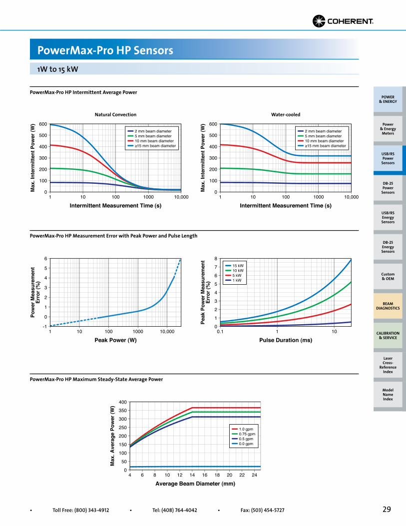
PowerMax-Pro HP Intermittent Average Power
PowerMax-Pro HP Measurement Error with Peak Power and Pulse Length
PowerMax-Pro HP Maximum Steady-State Average Power
1W to 15 kW
Max
. Ave
rage
Pow
er (W
)
0
50
100
150
200
250
300
350
400
4
Average Beam Diameter (mm)6 8 10 12 14 16 18 20 22 24
1.0 gpm0.75 gpm0.5 gpm0.0 gpm
Max
. Int
erm
itten
t Pow
er (W
)
0
600
1
Intermittent Measurement Time (s)10 100 1000 10,000
100
200
300
400
5002 mm beam diameter5 mm beam diameter10 mm beam diameter≥15 mm beam diameter
Max
. Int
erm
itten
t Pow
er (W
)
0
600
1
Intermittent Measurement Time (s)10 100 1000 10,000
100
200
300
400
5002 mm beam diameter5 mm beam diameter10 mm beam diameter≥15 mm beam diameter
Peak
Pow
er M
easu
rem
ent
Erro
r (%
)
0
8
0.1
Pulse Duration (ms)1 10
1
2
3
4
5
6
7 15 kW10 kW5 kW1 kW
Pow
er M
easu
rem
ent
Erro
r (%
)
-1
6
1
Peak Power (W)10 100 1000 10,000
0
1
2
3
4
5
Natural Convection Water-cooled

30 Superior Reliability & Performance • www.Coherent.com • [email protected]
PowerMax-Pro USB/RS HD Sensors200 mW to 150W
Device Specifications
Model PowerMax-Pro USB/RS 150 HD PowerMax-Pro USB/RS 150F HDWavelength Range 355 nm to 1100 nm; 355 nm to 1100 nm; 9 µm to 11 µm 9 µm to 11 µmAverage Power Range 200 mW to 150W 200 mW to 150W (17W max air-cooled, cont.) (65W max air-cooled, 5 min.)Maximum Pulsed Peak Power (W) 200Noise Equivalent Power (mW) Standard Mode (10 Hz) <4 High Speed Mode (20 kHz) <8 Snapshot Mode (625 kHz) <16Maximum Power Density (kW/cm2) 0.2 (150W)Maximum Peak Power Density (kW/cm2) 14Maximum Energy Density (J/cm2) 0.700 (10 ns; 355 nm)Rise Time (µs) ≤10Fall Time (µs) ≤10Detector Coating HDDiffuser NoneActive Area (mm) 30 x 30Minimum Beam Size (mm) 2.0 1.0 (up to 3% error)Maximum Beam Size (mm) 30Calibration Uncertainty (%)(k=2) at 810 nm ±2Spectral Compensation Accuracy (%) ±5Power Linearity (%) ±3Spatial Uniformity (%)(center 75% of aperture; 2.5 mm beam) ±5Calibration Wavelength (nm) 810Cooling Method Water/Air (intermittent) FanCable Type USB/RS-232Cable Length 4.2m (13.8 ft.)Part Number 1295921 (USB) 1295920 (USB) 1295923 (RS-232) 1295922 (RS-232)
PowerMax-Pro USB/RS 150 HD
PowerMax-Pro USB/RS 150F HD
Adjustable191 mm to 260 mm(7.52 to 10.24 in.)
90 mm(3.54 in.)
90 mm(3.54 in.)
30 mm(1.17 in.)
30 mm(1.18 in.)
30 mm(1.18 in.)
11 mm(0.44 in.)
51 mm(2.0 in.)
Cable Ends Not Shown in this View38 mm(1.5 in.)
110 mm(4.35 in.)
76 mm(3.0 in.)
Note: Detector surface is9.8 mm (0.38 in.) below frontface of aperture plate
51 mm (2.0 in.)Center to Center Slots
for 1/4-20 or M6 Screws
2X 15 mm(0.60 in.)
REF
45 mm(1.77 in.)
45 mm(1.77 in.)
13 mm(0.5 in.)
6 mm(0.25 in.)
13 mm(0.5 in.)
6 mm(0.25 in.)
USB or DB9RS Cable
2X 6 mm(0.25 in.)
2X 6 mm(0.25 in.)
M6X1.0 - 6H THD 10 mm (0.39 in.)Mounting Hole 1/4-20 UNC-2B THD
10 mm (0.39 in.)Mounting Hole
2X 6-32 UNC-2B THD 6 mm (0.25 in.)Mounting Holes
2X 6-32 UNC-2B THD 6 mm (0.25 in.)Mounting Holes
Adjustable191 mm to 260 mm(7.52 to 10.24 in.)
USB or DB9RS Cable
90 mm(3.54 in.)
45 mm(1.77 in.)
45 mm(1.77 in.)
6 mm(0.25 in.)
13 mm(0.5 in.)
6 mm(0.25 in.)
13 mm(0.5 in.)
2X 6 mm(0.25 in.)
2X 6 mm(0.25 in.)
M6X1.0 - 6H THD 10 mm (0.39 in.)Mounting Hole
30 mm(1.18 in.)
90 mm(3.54 in.)
104 mm(4.09 in.)
11 mm(0.44 in.)
23 mm(0.9 in.)
96 mm(3.79 in.)
38 mm(1.5 in.)
110 mm(4.35 in.)
51 mm(2.0 in.)
Cable Ends Not Shown in this View51 mm(2.0 in.)
76 mm(3.0 in.)
Note: Detector surface is9.8 mm (0.38 in.) below frontface of aperture plate
30 mm(1.18 in.)
1/4-20 UNC-2B THD 10 mm (0.39 in.)Mounting Hole
2X 6-32 UNC-2B THD 6 mm (0.25 in.)Mounting Holes
2X 6-32 UNC-2B THD 6 mm (0.25 in.)Mounting Holes
POWER & ENERGY
Custom & OEM
BEAM DIAGNOSTICS
CALIBRATION & SERVICE
Power & Energy
Meters
Laser Cross-
Reference Index
Model Name Index
DB-25Energy Sensors
USB/RSEnergy Sensors
DB-25Power
Sensors
USB/RSPower
Sensors
31• Toll Free: (800) 343-4912 • Tel: (408) 764-4042 • Fax: (503) 454-5727
PowerMax-Pro USB/RS HP Sensors
POWER & ENERGY
Custom & OEM
BEAM DIAGNOSTICS
CALIBRATION & SERVICE
Power & Energy
Meters
Laser Cross-
Reference Index
Model Name Index
DB-25Energy Sensors
USB/RSEnergy Sensors
DB-25Power
Sensors
USB/RSPower
Sensors
Device Specifications
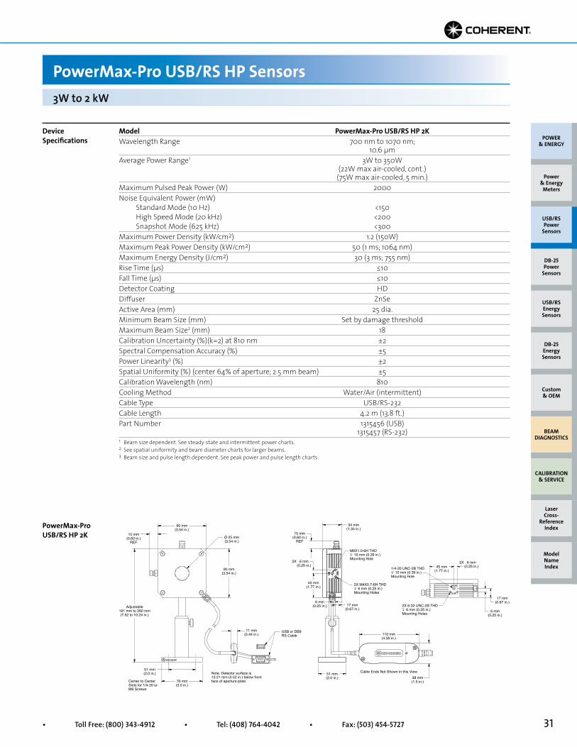
3W to 2 kW
Model PowerMax-Pro USB/RS HP 2KWavelength Range 700 nm to 1070 nm; 10.6 µmAverage Power Range1 3W to 350W (22W max air-cooled, cont.) (75W max air-cooled, 5 min.)Maximum Pulsed Peak Power (W) 2000Noise Equivalent Power (mW) Standard Mode (10 Hz) <150 High Speed Mode (20 kHz) <200 Snapshot Mode (625 kHz) <300Maximum Power Density (kW/cm2) 1.2 (150W)Maximum Peak Power Density (kW/cm2) 50 (1 ms; 1064 nm)Maximum Energy Density (J/cm2) 30 (3 ms; 755 nm)Rise Time (µs) ≤10Fall Time (µs) ≤10Detector Coating HDDiffuser ZnSeActive Area (mm) 25 dia.Minimum Beam Size (mm) Set by damage thresholdMaximum Beam Size2 (mm) 18Calibration Uncertainty (%)(k=2) at 810 nm ±2Spectral Compensation Accuracy (%) ±5Power Linearity3 (%) ±2Spatial Uniformity (%) (center 64% of aperture; 2.5 mm beam) ±5Calibration Wavelength (nm) 810Cooling Method Water/Air (intermittent)Cable Type USB/RS-232Cable Length 4.2 m (13.8 ft.)Part Number 1315456 (USB) 1315457 (RS-232)1 Beam size dependent. See steady-state and intermittent power charts.2 See spatial uniformity and beam diameter charts for larger beams.3 Beam size and pulse length dependent. See peak power and pulse length charts.
PowerMax-Pro USB/RS HP 2K
Adjustable191 mm to 260 mm(7.52 to 10.24 in.)
90 mm(3.54 in.)
Ø 25 mm(3.54 in.)
15 mm(0.60 in.)
REF
6 mm(0.25 in.)
45 mm(1.77 in.)
45 mm(1.77 in.)
17 mm(0.67 in.)
17 mm(0.67 in.)
6 mm(0.25 in.)
6 mm(0.25 in.)
2X 6 mm(0.25 in.)
2X
M6X1.0-6H THD 10 mm (0.39 in.)Mounting Hole
90 mm(3.54 in.)
15 mm(0.60 in.)
REF
34 mm(1.35 in.)
51 mm(2.0 in.)
51 mm(2.0 in.)
76 mm(3.0 in.)
Center to CenterSlots for 1/4-20 orM6 Screws
Note: Detector surface is13.21 mm (0.52 in.) below frontface of aperture plate
2X 6-32 UNC-2B THD 6 mm (0.25 in.)Mounting Holes
2X M4X0.7-6H THD 6 mm (0.25 in.)Mounting Holes
1/4-20 UNC-2B THD 10 mm (0.39 in.)Mounting Hole
11 mm(0.44 in.)
USB or DB9RS Cable
Cable Ends Not Shown in this View38 mm(1.5 in.)
110 mm(4.35 in.)
32 Superior Reliability & Performance • www.Coherent.com • [email protected]
Product Overview
PowerMax-USB/RS Sensors
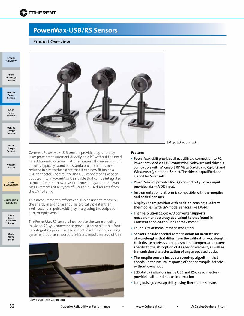
Coherent PowerMax-USB sensors provide plug-and-play laser power measurement directly on a PC without the need for additional electronic instrumentation. The measurement circuitry typically found in a standalone meter has been reduced in size to the extent that it can now fit inside a USB connector. The circuitry and USB connector have been adapted into a ‘PowerMax-USB’ cable that can be integrated to most Coherent power sensors providing accurate power measurements of all types of CW and pulsed sources from the UV to Far IR.
This measurement platform can also be used to measure the energy in a long laser pulse (typically greater than 1 millisecond in pulse width) by integrating the output of a thermopile sensor.
The PowerMax-RS sensors incorporate the same circuitry inside an RS-232 connector to provide a convenient platform for integrating power measurement inside laser processing systems that often incorporate RS-232 inputs instead of USB.
Features• PowerMax-USB provides direct USB 2.0 connection to PC. Power provided via USB connection. Software and driver is compatible with Microsoft XP, Vista (32-bit and 64-bit), and Windows 7 (32-bit and 64-bit). The driver is qualified and signed by Microsoft.• PowerMax-RS provides RS-232 connectivity. Power input provided via +5 VDC input.• Instrumentation platform is compatible with thermopiles and optical sensors• Displays beam position with position-sensing quadrant thermopiles (with LM-model sensors like LM-10)• High resolution 24-bit A/D converter supports measurement accuracy equivalent to that found in Coherent’s top-of-the-line LabMax meter• Four digits of measurement resolution• Sensors include spectral compensation for accurate use at wavelengths that differ from the calibration wavelength. Each device receives a unique spectral compensation curve specific to the absorption of its specific element, as well as transmission characterization of any associated optics.• Thermopile sensors include a speed-up algorithm that speeds up the natural response of the thermopile detector without overshoot• LED status indicators inside USB and RS-232 connectors provide health-and-status information• Long pulse joules capability using thermopile sensors
LM-45, LM-10 and LM-3
PowerMax-USB Connector
POWER & ENERGY
Custom & OEM
BEAM DIAGNOSTICS
CALIBRATION & SERVICE
Power & Energy
Meters
Laser Cross-
Reference Index
Model Name Index
DB-25Energy Sensors
USB/RSEnergy Sensors
DB-25Power
Sensors
USB/RSPower
Sensors
33• Toll Free: (800) 343-4912 • Tel: (408) 764-4042 • Fax: (503) 454-5727
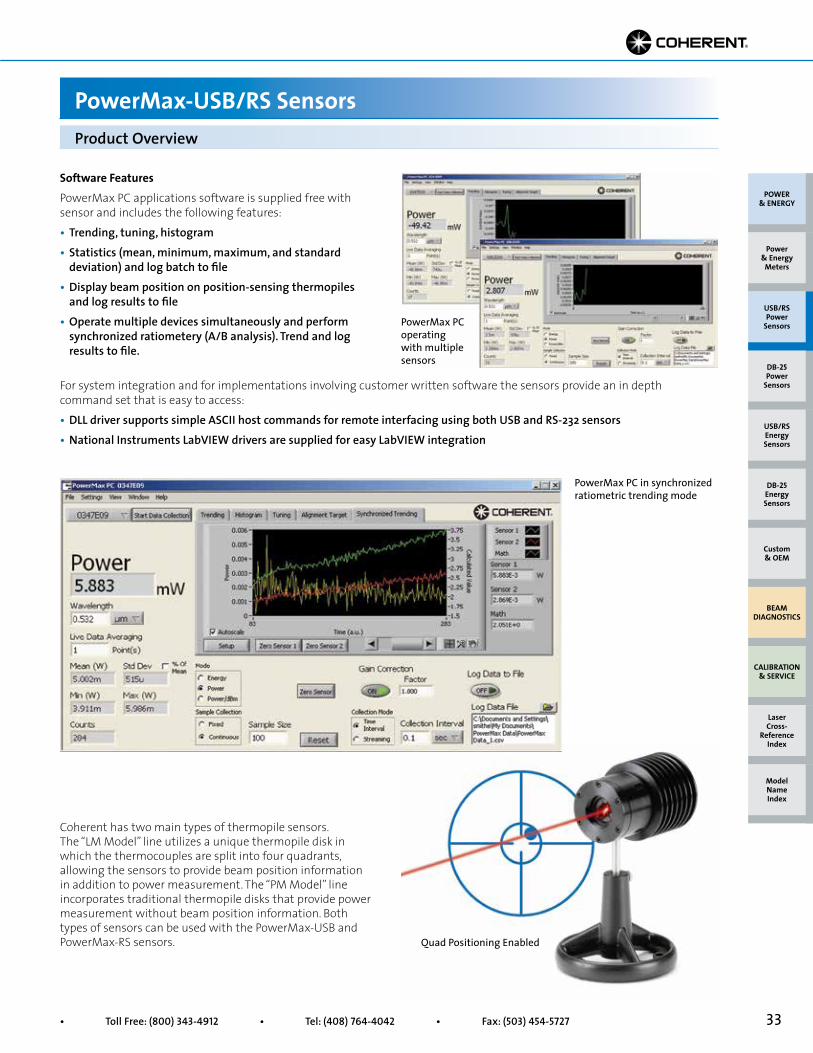
Software FeaturesPowerMax PC applications software is supplied free with sensor and includes the following features:• Trending, tuning, histogram• Statistics (mean, minimum, maximum, and standard deviation) and log batch to file• Display beam position on position-sensing thermopiles and log results to file• Operate multiple devices simultaneously and perform synchronized ratiometery (A/B analysis). Trend and log results to file.
Product Overview
PowerMax-USB/RS Sensors
Coherent has two main types of thermopile sensors. The “LM Model” line utilizes a unique thermopile disk in which the thermocouples are split into four quadrants, allowing the sensors to provide beam position information in addition to power measurement. The “PM Model” line incorporates traditional thermopile disks that provide power measurement without beam position information. Both types of sensors can be used with the PowerMax-USB and PowerMax-RS sensors.
PowerMax PC in synchronized ratiometric trending mode
Quad Positioning Enabled
PowerMax PC operating with multiple sensors
For system integration and for implementations involving customer written software the sensors provide an in depth command set that is easy to access:• DLL driver supports simple ASCII host commands for remote interfacing using both USB and RS-232 sensors • National Instruments LabVIEW drivers are supplied for easy LabVIEW integration
POWER & ENERGY
Custom & OEM
BEAM DIAGNOSTICS
CALIBRATION & SERVICE
Power & Energy
Meters
Laser Cross-
Reference Index
Model Name Index
DB-25Energy Sensors
USB/RSEnergy Sensors
DB-25Power
Sensors
USB/RSPower
Sensors

34 Superior Reliability & Performance • www.Coherent.com • [email protected]
Measurement Accuracy =
where U = ‘Percent Calibration Uncertainty’ and W = ‘Wavelength Accuracy’
Example:
PowerMax-USB LM-10 used at 1064 nm
U = 2%W = 1.5%
Measurement Accuracy = = = 2.5%
Applying Wavelength Compensation Accuracy
PowerMax-USB/RS Sensors
Overall measurement accuracy is a combination of calibration uncertainty (found in the sensor specification tables) and the wavelength compensation accuracy (found in the “Wavelength Compensation Accuracy” table, below).
The combined accuracy is based upon practices outlined in the National Institute of Standards Guidelines for Evaluating and Expressing Uncertainty (NIST Technical Note 1297, 1994 Edition). The combined accuracy of the measurement is calculated by using the law of propagation of uncertainty using the “root-sum-of-square” (square root of the sum of squares), sometimes described as “summing in quadrature” where:
Wavelength Calibration Compensation WavelengthSensor Accuracy (%) (nm)All PM-model and LM-model thermopiles ±1.5 10,600PS-model ±1.5 514 UV/VIS optical sensor ±4% (325 nm to 900 nm) 514 ±5% (900 nm to 1065 nm)
Wavelength Compensation Accuracy
22 + 1.52 4 + 2.3
U2 + W2
Abs
orpt
ion
(%)
0.80
0.85
0.90
0.95
1.0
1.05
1.1
0.1
Wavelength (µm)1 10
Black Coating w/Quartz WindowBlack Coating
Broadband CoatingUV Coating
Coherent uses three primary coatings to capture the incident radiation on our thermal sensors. The specifications for each sensor list which coating is used. Typical wavelength ranges and response curves for these coatings are shown in the chart below. Each sensor contains a spectral curve generated from reflectance measurements taken with spectrometers. The reflectance data are converted into a wavelength compensation look-up table that is loaded into the sensor. This data is accessed by selecting a wavelength of operation in the software.
Absorption of Thermal Sensor Coating
POWER & ENERGY
Custom & OEM
BEAM DIAGNOSTICS
CALIBRATION & SERVICE
Power & Energy
Meters
Laser Cross-
Reference Index
Model Name Index
DB-25Energy Sensors
USB/RSEnergy Sensors
DB-25Power
Sensors
USB/RSPower
Sensors
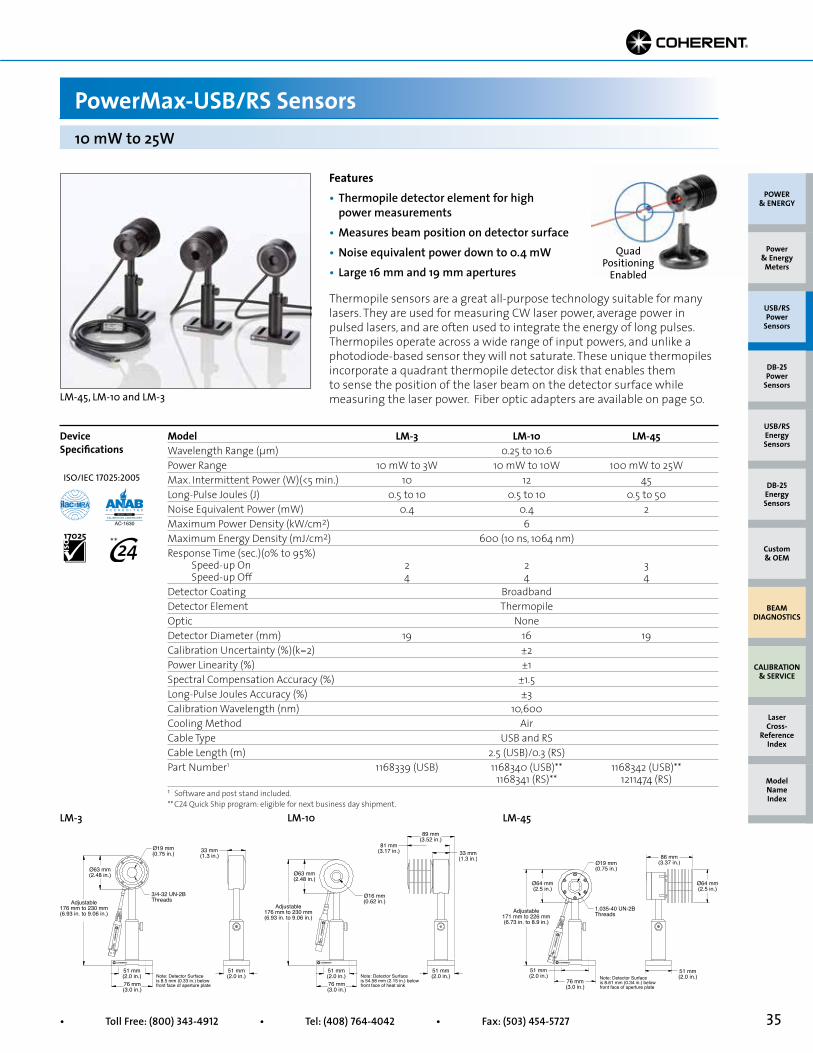
35• Toll Free: (800) 343-4912 • Tel: (408) 764-4042 • Fax: (503) 454-5727
Quad Positioning
Enabled
PowerMax-USB/RS Sensors
Model LM-3 LM-10 LM-45Wavelength Range (µm) 0.25 to 10.6 Power Range 10 mW to 3W 10 mW to 10W 100 mW to 25WMax. Intermittent Power (W)(<5 min.) 10 12 45Long-Pulse Joules (J) 0.5 to 10 0.5 to 10 0.5 to 50Noise Equivalent Power (mW) 0.4 0.4 2Maximum Power Density (kW/cm2) 6 Maximum Energy Density (mJ/cm2) 600 (10 ns, 1064 nm) Response Time (sec.)(o% to 95%) Speed-up On 2 2 3 Speed-up Off 4 4 4Detector Coating Broadband Detector Element Thermopile Optic None Detector Diameter (mm) 19 16 19Calibration Uncertainty (%)(k=2) ±2 Power Linearity (%) ±1 Spectral Compensation Accuracy (%) ±1.5 Long-Pulse Joules Accuracy (%) ±3 Calibration Wavelength (nm) 10,600 Cooling Method Air Cable Type USB and RS Cable Length (m) 2.5 (USB)/0.3 (RS) Part Number1 1168339 (USB) 1168340 (USB)** 1168342 (USB)** 1168341 (RS)** 1211474 (RS)
Device Specifications
10 mW to 25W
LM-45LM-3
Ø63 mm(2.48 in.)
51 mm(2.0 in.)
51 mm(2.0 in.)
81 mm(3.17 in.)
89 mm(3.52 in.)
33 mm(1.3 in.)
76 mm(3.0 in.)
Note: Detector Surfaceis 54.58 mm (2.15 in.) belowfront face of heat sink
Ø16 mm(0.62 in.)
Adjustable176 mm to 230 mm(6.93 in. to 9.06 in.)
LM-10
Features• Thermopile detector element for high power measurements• Measures beam position on detector surface• Noise equivalent power down to 0.4 mW• Large 16 mm and 19 mm apertures Thermopile sensors are a great all-purpose technology suitable for many lasers. They are used for measuring CW laser power, average power in pulsed lasers, and are often used to integrate the energy of long pulses. Thermopiles operate across a wide range of input powers, and unlike a photodiode-based sensor they will not saturate. These unique thermopiles incorporate a quadrant thermopile detector disk that enables them to sense the position of the laser beam on the detector surface while measuring the laser power. Fiber optic adapters are available on page 50.LM-45, LM-10 and LM-3
1 Software and post stand included.** C24 Quick Ship program: eligible for next business day shipment.
POWER & ENERGY
Custom & OEM
BEAM DIAGNOSTICS
CALIBRATION & SERVICE
Power & Energy
Meters
Laser Cross-
Reference Index
Model Name Index
DB-25Energy Sensors
USB/RSEnergy Sensors
DB-25Power
Sensors
USB/RSPower
Sensors
Ø63 mm(2.48 in.)
51 mm(2.0 in.)
51 mm(2.0 in.)
33 mm(1.3 in.)
76 mm(3.0 in.)
Note: Detector Surfaceis 8.5 mm (0.33 in.) belowfront face of aperture plate
Ø19 mm(0.75 in.)
3/4-32 UN-2BThreadsAdjustable
176 mm to 230 mm(6.93 in. to 9.06 in.)
Ø19 mm(0.75 in.)
86 mm(3.37 in.)
Adjustable171 mm to 226 mm(6.73 in. to 8.9 in.)
51 mm(2.0 in.)
51 mm(2.0 in.)
1.035-40 UN-2BThreads
Ø64 mm(2.5 in.)
Ø64 mm(2.5 in.)
76 mm(3.0 in.)
Note: Detector Surfaceis 8.61 mm (0.34 in.) belowfront face of aperture plate
ISO/IEC 17025:2005
**
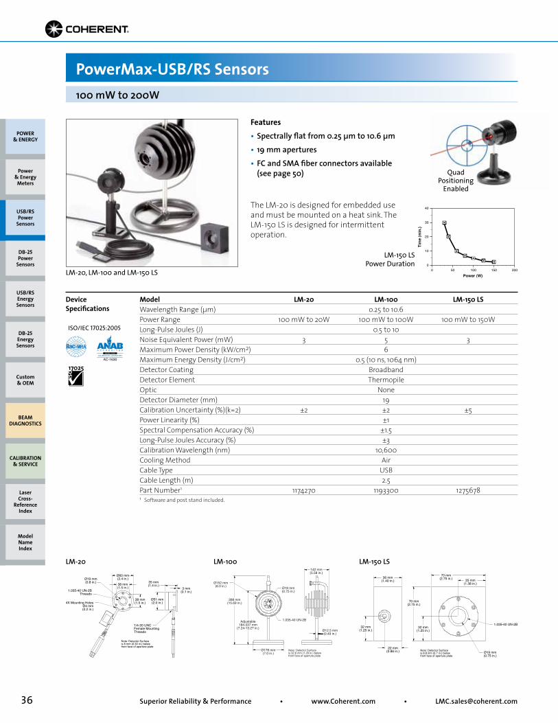
36 Superior Reliability & Performance • www.Coherent.com • [email protected]
Quad Positioning
Enabled
PowerMax-USB/RS Sensors
Model LM-20 LM-100 LM-150 LSWavelength Range (µm) o.25 to 10.6 Power Range 100 mW to 20W 100 mW to 100W 100 mW to 150W Long-Pulse Joules (J) 0.5 to 10Noise Equivalent Power (mW) 3 5 3Maximum Power Density (kW/cm2) 6 Maximum Energy Density (J/cm2) 0.5 (10 ns, 1064 nm) Detector Coating Broadband Detector Element Thermopile Optic None Detector Diameter (mm) 19Calibration Uncertainty (%)(k=2) ±2 ±2 ±5 Power Linearity (%) ±1 Spectral Compensation Accuracy (%) ±1.5 Long-Pulse Joules Accuracy (%) ±3 Calibration Wavelength (nm) 10,600 Cooling Method Air Cable Type USB Cable Length (m) 2.5 Part Number1 1174270 1193300 1275678
Device Specifications
100 mW to 200W
LM-20
Features• Spectrally flat from 0.25 µm to 10.6 µm• 19 mm apertures• FC and SMA fiber connectors available (see page 50)
The LM-20 is designed for embedded use and must be mounted on a heat sink. The LM-150 LS is designed for intermittent operation.
LM-20, LM-100 and LM-150 LS
1 Software and post stand included.
Ø178 mm(7.0 in.)
398 mm(15.69 in.)
Ø152 mm(6.0 in.) Ø19 mm
(0.75 in.)
142 mm(5.58 in.)
Ø12.5 mm(0.49 in.)
1.035-40 UN-2BAdjustable184-337 mm
(7.24-13.27 in.)
Note: Detector Surfaceis 32.6 mm (1.29 in.) belowfront face of aperture plate
LM-100
POWER & ENERGY
Custom & OEM
BEAM DIAGNOSTICS
CALIBRATION & SERVICE
Power & Energy
Meters
Laser Cross-
Reference Index
Model Name Index
DB-25Energy Sensors
USB/RSEnergy Sensors
DB-25Power
Sensors
USB/RSPower
Sensors
1/4-20 UNCFemale MountingThreads
Ø60 mm(2.4 in.)Ø19 mm
(0.8 in.)
1.035-40 UN-2BThreads
4X Mounting HolesØ4 mm(0.2 in.)
Ø51 mm(2.0 in.)
38 mm(1.5 in.)
35 mm(1.4 in.)
38 mm(1.5 in.)
3 mm(0.1 in.)
Note: Detector Surfaceis 8 mm (0.30 in.) belowfront face of aperture plate
ISO/IEC 17025:2005
00
Power (W)
Tim
e (m
in.)
10
20
30
40
50 100 150 200
LM-150 LS Power Duration
LM-150 LS
Ø19 mm(0.75 in.)
22 mm(0.86 in.)
32 mm(1.25 in.)
36 mm(1.40 in.)
70 mm(2.75 in.) 35 mm
(1.38 in.)
32 mm(1.25 in.)
70 mm(2.75 in.)
1.035-40 UN-2B
Note: Detector Surfaceis 8.8 mm (0.7 in.) belowfront face of aperture plate
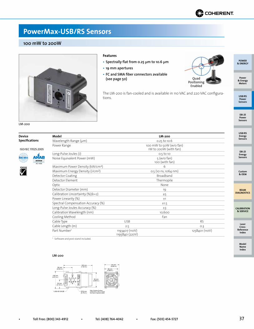
37• Toll Free: (800) 343-4912 • Tel: (408) 764-4042 • Fax: (503) 454-5727
Quad Positioning
Enabled
PowerMax-USB/RS Sensors
Model LM-200 Wavelength Range (µm) o.25 to 10.6 Power Range 100 mW to 50W (w/o fan) 1W to 200W (with fan)Long-Pulse Joules (J) 0.5 to 10Noise Equivalent Power (mW) 5 (w/o fan) 100 (with fan)Maximum Power Density (kW/cm2) 6 Maximum Energy Density (J/cm2) 0.5 (10 ns, 1064 nm) Detector Coating Broadband Detector Element Thermopile Optic None Detector Diameter (mm) 19Calibration Uncertainty (%)(k=2) ±5 Power Linearity (%) ±1 Spectral Compensation Accuracy (%) ±1.5 Long-Pulse Joules Accuracy (%) ±3 Calibration Wavelength (nm) 10,600 Cooling Method Fan Cable Type USB RS Cable Length (m) 2.5 0.3 Part Number1 1193407 (110V) 1258401 (110V) 1195840 (220V)
Device Specifications
100 mW to 200W
LM-200
Features• Spectrally flat from 0.25 µm to 10.6 µm• 19 mm apertures• FC and SMA fiber connectors available (see page 50)
The LM-200 is fan-cooled and is available in 110 VAC and 220 VAC configura-tions.
LM-200
1 Software and post stand included.
Ø19 mm(0.75 in.)
183 mm(7.22 in.)56 mm
(2.22 in.)
109 mm(4.31 in.)
55 mm(2.15 in.)
93 mm(3.68 in.)
94 mm(3.69 in.)
86 mm(3.38 in.)
1.035-40 UN-2B Note: Detector Surfaceis 32.6 mm (1.29 in.) belowfront face of aperture plate
POWER & ENERGY
Custom & OEM
BEAM DIAGNOSTICS
CALIBRATION & SERVICE
Power & Energy
Meters
Laser Cross-
Reference Index
Model Name Index
DB-25Energy Sensors
USB/RSEnergy Sensors
DB-25Power
Sensors
USB/RSPower
Sensors
ISO/IEC 17025:2005
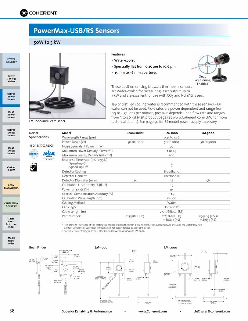
38 Superior Reliability & Performance • www.Coherent.com • [email protected]
POWER & ENERGY
Custom & OEM
BEAM DIAGNOSTICS
CALIBRATION & SERVICE
Power & Energy
Meters
Laser Cross-
Reference Index
Model Name Index
DB-25Energy Sensors
USB/RSEnergy Sensors
DB-25Power
Sensors
USB/RSPower
Sensors
Features• Water-cooled• Spectrally flat from 0.25 µm to 10.6 µm• 35 mm to 56 mm apertures
LM-1000 and BeamFinder
These position sensing kilowatt thermopile sensors are water-cooled for measuring laser output up to 3 kW and are excellent for use with CO2 and Nd:YAG lasers.
Tap or distilled cooling water is recommended with these sensors – DI water can not be used. Flow rates are power dependent and range from 0.5 to 4 gallons per minute; pressure depends upon flow rate and ranges from 3 to 40 PSI (visit product pages at www.Coherent.com/LMC for more technical details). See page 50 for RS model power supply accessory.
50W to 5 kW
PowerMax-USB/RS Sensors
Model BeamFinder LM-1000 LM-5000Wavelength Range (µm) 0.25 to 10.6Power Range (W) 50 to 1000 50 to 1000 50 to 5000Noise Equivalent Power (mW) 20Maximum Power Density1 (kW/cm2) 1 to 2.5Maximum Energy Density (mJ/cm2) 500Response Time (sec.)(o% to 95%) Speed-up On 4 Speed-up Off 6Detector Coating BroadbandDetector Element ThermopileDetector Diameter (mm) 35 38 56Calibration Uncertainty (%)(k=2) ±5Power Linearity (%) ±1Spectral Compensation Accuracy (%) ±1.5Calibration Wavelength (nm) 10,600Cooling Method WaterCable Type USB and RSCable Length (m) 2.5 (USB)/0.3 (RS)Part Number2 1233118 (USB) 1174268 (USB) 1174269 (USB) 1180872 (RS) 1181653 (RS)
Device Specifications
1 The damage resistance of the coating is dependent upon the beam size and profile, the average power level, and the water flow rate. Contact Coherent or your local representative for details related to your application.2 Software, water fittings and post stand included with LM-1000 and LM-5000.
LM-1000 USB
LM-5000
Ø38 mm(1.50 in.)
69 mm(2.70 in.)
95 mm(3.75 in.)
13 mm(0.53 in.)
15 mm(0.58 in.)
95 mm(3.75 in.)
Adjustable134 mm to 430 mm(5.27 in. to 17.0 in.)
Ø178 mm(7.0 in.)
Note: Detector Surfaceis 16 mm (0.63 in.) belowfront face of aperture plate
Adjustable161-457 mm
(6.34-18.0 in.)
Ø178 mm(7.0 in.)
15 mm(0.61 in.)
17 mm(0.67 in.)
122 mm(4.81 in.)
Ø56 mm(2.20 in.)
122 mm(4.81 in.)
81 mm(3.21 in.)
398 mm(15.69 in.)
Ø12.5 mm(0.49 in.)
Note: Detector Surfaceis 17 mm (0.69 in.) belowfront face of aperture plate
Quad Positioning
Enabled
BeamFinder
Ø35 mm(1.39 in.)
83 mm(3.25 in.)
83 mm(3.25 in.)
63 mm(2.5 in.)
63 mm(2.5 in.)
41 mm(1.63 in.)
41 mm(1.63 in.)29 mm
(1.16 in.) 19 mm(0.75 in.)
4X Ø3 mm(0.11 in.)
Thru
19 mm(0.75 in.)
25 mm(1.0 in.)
ISO/IEC 17025:2005

39• Toll Free: (800) 343-4912 • Tel: (408) 764-4042 • Fax: (503) 454-5727
51 mm(2.0 in.)
76 mm(3.01 in.)
48 mm(1.91 in.)
Ø10 mm(0.39 in.)
Ø84 mm(3.30 in.)
Adjustable198 mm to 252 mm(7.79 in. to 9.97 in.)
Light TubePS10 only
51 mm(2.0 in.)
76 mm(3.0 in.)
Note: Detector Surfaceis 19.0 mm (0.75 in.) belowfront face of aperture plate
Ø84 mm(3.3 in.)
51 mm(2.0 in.)
51 mm(2.0 in.)
48 mm(1.91 in.)
76 mm(3.0 in.)
Note: Detector Surfaceis 19.0 mm (0.75 in.) belowfront face of aperture plate
Ø19 mm(0.76 in.)
Adjustable197 mm to 252 mm(7.75 in. to 9.93 in.)
PowerMax-USB/RS Sensors
Model PS10 PS10Q PS19Q PS19Wavelength Range (nm) 1903 to 11,000 300 to 2100 300 to 2100 1903 to 11,000Power Range 100 µW to 1W 100 µW to 1W 100 µW to 1WMax. Intermittent Power (W)(<5 min.) 3Long-pulse Joules (J) 0.001 to 1Noise Equivalent Power (µW) 3 3 3 5Maximum Thermal Drift1 (µW) ±40 ±25 ±25 ±400Maximum Power Density (W/cm2) 500Maximum Energy Density (mJ/cm2) 50 (10 ns, 1064 nm)Response Time (sec.)(o% to 95%) Speed-up On 2 Speed-up Off 3Detector Coating BlackDetector Element ThermopileOptic None Quartz Quartz NoneDetector Diameter (mm) 10 10 19 19Calibration Uncertainty (%)(k=2) ±1Power Linearity (%) ±1Spectral Compensation Accuracy (%) ±1.5Long-pulse Joules Accuracy (%) ±3Calibration Wavelength (nm) 514Cooling Method AirCable Type USB and RSCable Length (m) 2.5 (USB)/0.3 (RS)Part Number2 1174260 (USB)** 1287077 (USB) 1168343 (USB)** 1174261 (USB)** 1288992 (RS) 1179504 (RS)
The PS10 and PS19 model sensors are thermally stabilized, amplifiedthermopile power sensors with a broad spectral response, high sensitivity,and a large active area. These sensors are ideal for measuring laser diodes,HeNe and HeCd lasers, and small ion lasers. The PS10 model includes a lighttube mounted to the front of the housing, which minimizes the effects ofbackground radiation. The light tube can be removed and replaced by FC orSMA fiber connectors (see Accessories - page 50). Where optimum stability is required, specify the PS19Q, which include a wedged quartz windowfor applications from 0.3 to 2.1 µm. The quartz window more effectivelyeliminates thermal background radiation and the effects of air currents.
Device Specifications
Features• Thermally stabilized design for low power sensitivity• Noise equivalent power down to 3 µW• Spectrally flat; good for broadband light sources
100 µW to 1W
PS10 and PS19Q
1 Power stability over 30 minutes in typical lab environment.2 Software and post stand included.
3 190 nm to 300 nm operation restricted to <100 mW average power and <250 W/cm2 power density.** C24 Quick Ship program: eligible for next business day shipment.
PS19Q/PS19PS10Q/PS10
POWER & ENERGY
Custom & OEM
BEAM DIAGNOSTICS
CALIBRATION & SERVICE
Power & Energy
Meters
Laser Cross-
Reference Index
Model Name Index
DB-25Energy Sensors
USB/RSEnergy Sensors
DB-25Power
Sensors
USB/RSPower
Sensors
ISO/IEC 17025:2005
**
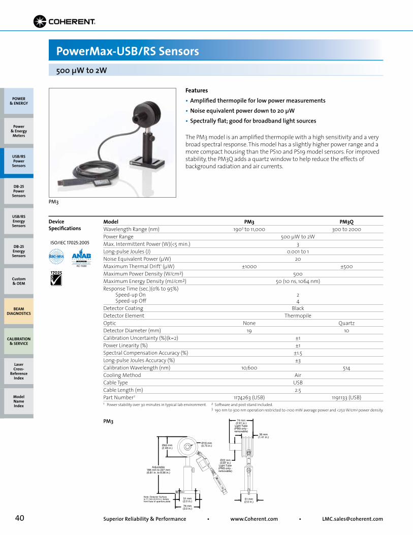
40 Superior Reliability & Performance • www.Coherent.com • [email protected]
51 mm(2.0 in.)
36 mm(1.41 in.)
Ø19 mm(0.75 in.)
Ø22 mm(0.87 in.)
Light Tube(PM3 only -removable)
74 mm(2.91 in.)
Light Tube(PM3 only -removable)
Ø63 mm(2.48 in.)
Adjustable186 mm to 227 mm(6.81 in. to 8.96 in.)
51 mm(2.0 in.)
76 mm(3.0 in.)
Note: Detector Surfaceis 11 mm (0.44 in.) belowfront face of aperture plate
PowerMax-USB/RS Sensors
Model PM3 PM3QWavelength Range (nm) 1903 to 11,000 300 to 2000Power Range 500 µW to 2WMax. Intermittent Power (W)(<5 min.) 3Long-pulse Joules (J) 0.001 to 1Noise Equivalent Power (µW) 20Maximum Thermal Drift1 (µW) ±1000 ±500Maximum Power Density (W/cm2) 500Maximum Energy Density (mJ/cm2) 50 (10 ns, 1064 nm)Response Time (sec.)(o% to 95%) Speed-up On 2 Speed-up Off 4 Detector Coating BlackDetector Element ThermopileOptic None QuartzDetector Diameter (mm) 19 10Calibration Uncertainty (%)(k=2) ±1Power Linearity (%) ±1Spectral Compensation Accuracy (%) ±1.5Long-pulse Joules Accuracy (%) ±3Calibration Wavelength (nm) 10,600 514Cooling Method AirCable Type USBCable Length (m) 2.5Part Number2 1174263 (USB) 1191133 (USB)
The PM3 model is an amplified thermopile with a high sensitivity and a very broad spectral response. This model has a slightly higher power range and a more compact housing than the PS10 and PS19 model sensors. For improved stability, the PM3Q adds a quartz window to help reduce the effects of background radiation and air currents.
Device Specifications
Features• Amplified thermopile for low power measurements• Noise equivalent power down to 20 µW• Spectrally flat; good for broadband light sources
500 µW to 2W
PM3
1 Power stability over 30 minutes in typical lab environment. 2 Software and post stand included.3 190 nm to 300 nm operation restricted to <100 mW average power and <250 W/cm2 power density.
PM3
POWER & ENERGY
Custom & OEM
BEAM DIAGNOSTICS
CALIBRATION & SERVICE
Power & Energy
Meters
Laser Cross-
Reference Index
Model Name Index
DB-25Energy Sensors
USB/RSEnergy Sensors
DB-25Power
Sensors
USB/RSPower
Sensors
ISO/IEC 17025:2005

41• Toll Free: (800) 343-4912 • Tel: (408) 764-4042 • Fax: (503) 454-5727
POWER & ENERGY
Custom & OEM
BEAM DIAGNOSTICS
CALIBRATION & SERVICE
Power & Energy
Meters
Laser Cross-
Reference Index
Model Name Index
DB-25Energy Sensors
USB/RSEnergy Sensors
DB-25Power
Sensors
USB/RSPower
Sensors
PowerMax-USB/RS Sensors5 µW to >100 mW
Model UV/VIS Wand UV/VISWavelength Range (nm) 325 to 1065Power Range1 5 µW to >100 mW 8.5 µW to >140 mWNoise Equivalent Power (nW) 100 170Maximum Power Density (W/cm2) 20Response Time (sec.) Speed-up On - Speed-up Off (o% to 100%) 0.1 0.5 Detector Element Silicon photodiodeOptic ND2 Diffuse QuartzDetector Diameter (mm) 10 8Calibration Uncertainty (%)(k=2) ±1Power Linearity (%) ±1Spectral Compensation Accuracy (%) ±4 (325 to 900 nm) ±5 (900 to 1065 nm)Calibration Wavelength (nm) 514Cooling Method AirCable Type USBCable Length (m) 2.5Part Number2 1168337** 1212310**
Device Specifications
The PowerMax-USB UV/VIS Quantum sensors incorporate a Silicon photo-diode, for measurement of power from 5 µW to several hundred milliwatts. The measureable power varies significantly by wavelength. See the chart on the next page.
Spectrally calibrated filters are used to attenuate the laser beam, thus allow-ing for a higher average power measurement than is typically possible with a photodiode. They work with CW (continuous wave) as well as pulsed sources greater than 100 pps. The standard UV/VIS has a removable nose cone that can be used to reduce stray light, which is helpful when measuring on the low end of the power range, and the Wand UV/VIS incorporates a thin profile to fit into tight locations. See page 50 for Wand sensor fiber adapters.
UV/VIS Quantum
Features• Large 8 mm and 10 mm apertures• High-sensitivity Silicon photodiode• Low power measurements down to 5 µW (wavelength dependent)• Spectral response from 325 nm to 1065 nm
1 Wavelength dependent, see chart on next page.2 Software and post stand included.** C24 Quick Ship program: eligible for next business day shipment.
51 mm(2.0 in.)
20 mm(0.81 in.)
Ø10 mm(0.4 in.)
43 mm(1.69 in.)
51 mm(2.0 in.)
Adjustable165 mm to 220 mm(6.5 in. to 8.66 in.)
51 mm(2.0 in.)
76 mm(3.0 in.)
Note: Detector Surfaceis 3.56 mm (0.14 in.) belowfront face of aperture plate
Note: Light shield is removable
Wand UV/VIS Quantum
UV/VIS Wand and UV/VIS Sensor
Ø8 mm(0.3 in.)
50 mm(1.9 in.)
76 mm(3.0 in.)
51 mm(2.0 in.)
152 mm(6.0 in.)
19 mm(0.7 in.)
13 mm(0.5 in.)
23 mm(0.9 in.)5.5 mm
(0.22 in.)
34 mm(1.3 in.)
Adjustable121 mm to 92 mm(4.8 in. to 3.6 in.)
ISO/IEC 17025:2005
**
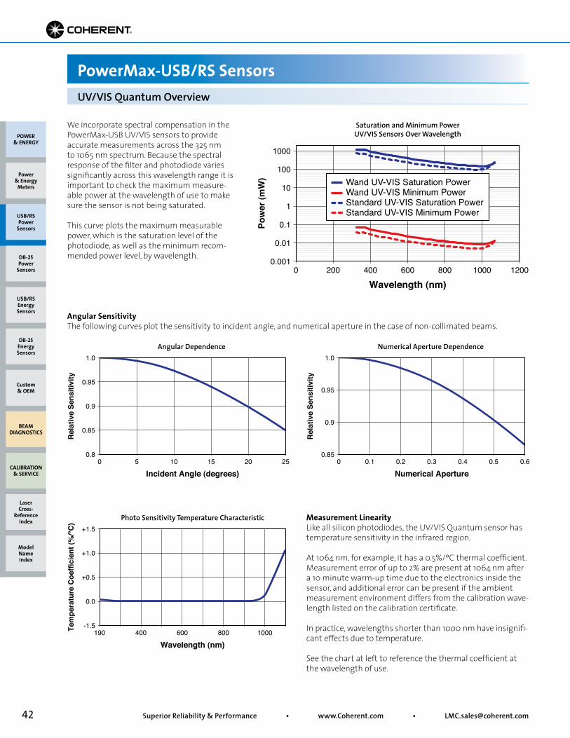
42 Superior Reliability & Performance • www.Coherent.com • [email protected]
Wavelength (nm)
Tem
pera
ture
Coe
ffici
ent (
%/°C
)
-1.5190
+1.5
0.0
+0.5
+1.0
400 600 800 1000
We incorporate spectral compensation in the PowerMax-USB UV/VIS sensors to provide accurate measurements across the 325 nm to 1065 nm spectrum. Because the spectral response of the filter and photodiode varies significantly across this wavelength range it is important to check the maximum measure-able power at the wavelength of use to make sure the sensor is not being saturated.
This curve plots the maximum measurable power, which is the saturation level of the photodiode, as well as the minimum recom-mended power level, by wavelength.
Angular SensitivityThe following curves plot the sensitivity to incident angle, and numerical aperture in the case of non-collimated beams.
POWER & ENERGY
Custom & OEM
BEAM DIAGNOSTICS
CALIBRATION & SERVICE
Power & Energy
Meters
Laser Cross-
Reference Index
Model Name Index
DB-25Energy Sensors
USB/RSEnergy Sensors
DB-25Power
Sensors
USB/RSPower
Sensors
PowerMax-USB/RS SensorsUV/VIS Quantum Overview
Measurement LinearityLike all silicon photodiodes, the UV/VIS Quantum sensor has temperature sensitivity in the infrared region.
At 1064 nm, for example, it has a 0.5%/ºC thermal coefficient. Measurement error of up to 2% are present at 1064 nm after a 10 minute warm-up time due to the electronics inside the sensor, and additional error can be present if the ambient measurement environment differs from the calibration wave-length listed on the calibration certificate.
In practice, wavelengths shorter than 1000 nm have insignifi-cant effects due to temperature.
See the chart at left to reference the thermal coefficient at the wavelength of use.
Saturation and Minimum Power UV/VIS Sensors Over Wavelength
Angular Dependence Numerical Aperture Dependence
Photo Sensitivity Temperature Characteristic
Wavelength (nm)
Saturation and Minimum PowerUV/VIS Sensors Over Wavelength
Pow
er (m
W)
0.0010 1200
1000
0.01
0.1
1
10
100
200 400 600 800 1000
Wand UV-VIS Saturation PowerWand UV-VIS Minimum PowerStandard UV-VIS Saturation PowerStandard UV-VIS Minimum Power
Incident Angle (degrees)
Angular Dependence
Rel
ativ
e Se
nsiti
vity
0.80 25
1.0
0.85
0.9
0.95
5 10 15 20
Numerical Aperture
Numerical Aperture Dependence
Rel
ativ
e Se
nsiti
vity
0.850 0.6
1.0
0.9
0.95
0.1 0.2 0.3 0.4 0.5
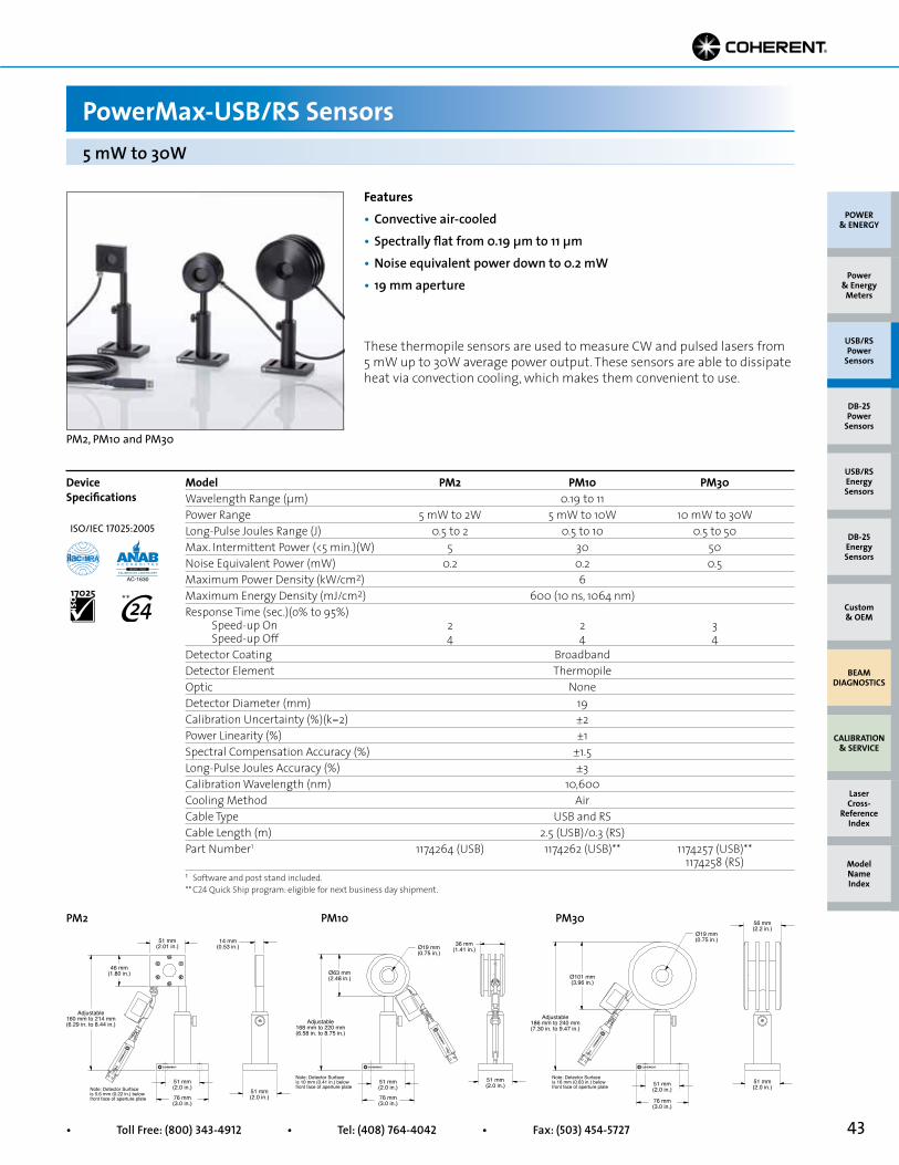
43• Toll Free: (800) 343-4912 • Tel: (408) 764-4042 • Fax: (503) 454-5727
51 mm(2.0 in.)
56 mm(2.2 in.)
Ø19 mm(0.75 in.)
Ø101 mm(3.96 in.)
Adjustable186 mm to 240 mm(7.30 in. to 9.47 in.)
51 mm(2.0 in.)
76 mm(3.0 in.)
Note: Detector Surfaceis 16 mm (0.63 in.) belowfront face of aperture plate
Model PM2 PM10 PM30Wavelength Range (µm) 0.19 to 11Power Range 5 mW to 2W 5 mW to 10W 10 mW to 30WLong-Pulse Joules Range (J) 0.5 to 2 0.5 to 10 0.5 to 50Max. Intermittent Power (<5 min.)(W) 5 30 50Noise Equivalent Power (mW) 0.2 0.2 0.5Maximum Power Density (kW/cm2) 6Maximum Energy Density (mJ/cm2) 600 (10 ns, 1064 nm)Response Time (sec.)(o% to 95%) Speed-up On 2 2 3 Speed-up Off 4 4 4Detector Coating BroadbandDetector Element ThermopileOptic NoneDetector Diameter (mm) 19Calibration Uncertainty (%)(k=2) ±2Power Linearity (%) ±1Spectral Compensation Accuracy (%) ±1.5Long-Pulse Joules Accuracy (%) ±3Calibration Wavelength (nm) 10,600Cooling Method AirCable Type USB and RSCable Length (m) 2.5 (USB)/0.3 (RS)Part Number1 1174264 (USB) 1174262 (USB)** 1174257 (USB)** 1174258 (RS)1 Software and post stand included.** C24 Quick Ship program: eligible for next business day shipment.
Features• Convective air-cooled• Spectrally flat from 0.19 µm to 11 µm• Noise equivalent power down to 0.2 mW• 19 mm aperture
PM2, PM10 and PM30
These thermopile sensors are used to measure CW and pulsed lasers from 5 mW up to 30W average power output. These sensors are able to dissipate heat via convection cooling, which makes them convenient to use.
Device Specifications
PM2 PM10 PM30
5 mW to 30W
PowerMax-USB/RS Sensors
51 mm(2.0 in.)
36 mm(1.41 in.)Ø19 mm
(0.75 in.)
Ø63 mm(2.48 in.)
Adjustable168 mm to 220 mm(6.58 in. to 8.75 in.)
51 mm(2.0 in.)
76 mm(3.0 in.)
Note: Detector Surfaceis 10 mm (0.41 in.) belowfront face of aperture plate
51 mm(2.0 in.)
14 mm(0.53 in.)
51 mm(2.01 in.)
46 mm(1.80 in.)
Adjustable160 mm to 214 mm(6.29 in. to 8.44 in.)
51 mm(2.0 in.)76 mm
(3.0 in.)
Note: Detector Surfaceis 5.6 mm (0.22 in.) belowfront face of aperture plate
POWER & ENERGY
Custom & OEM
BEAM DIAGNOSTICS
CALIBRATION & SERVICE
Power & Energy
Meters
Laser Cross-
Reference Index
Model Name Index
DB-25Energy Sensors
USB/RSEnergy Sensors
DB-25Power
Sensors
USB/RSPower
Sensors
ISO/IEC 17025:2005
**
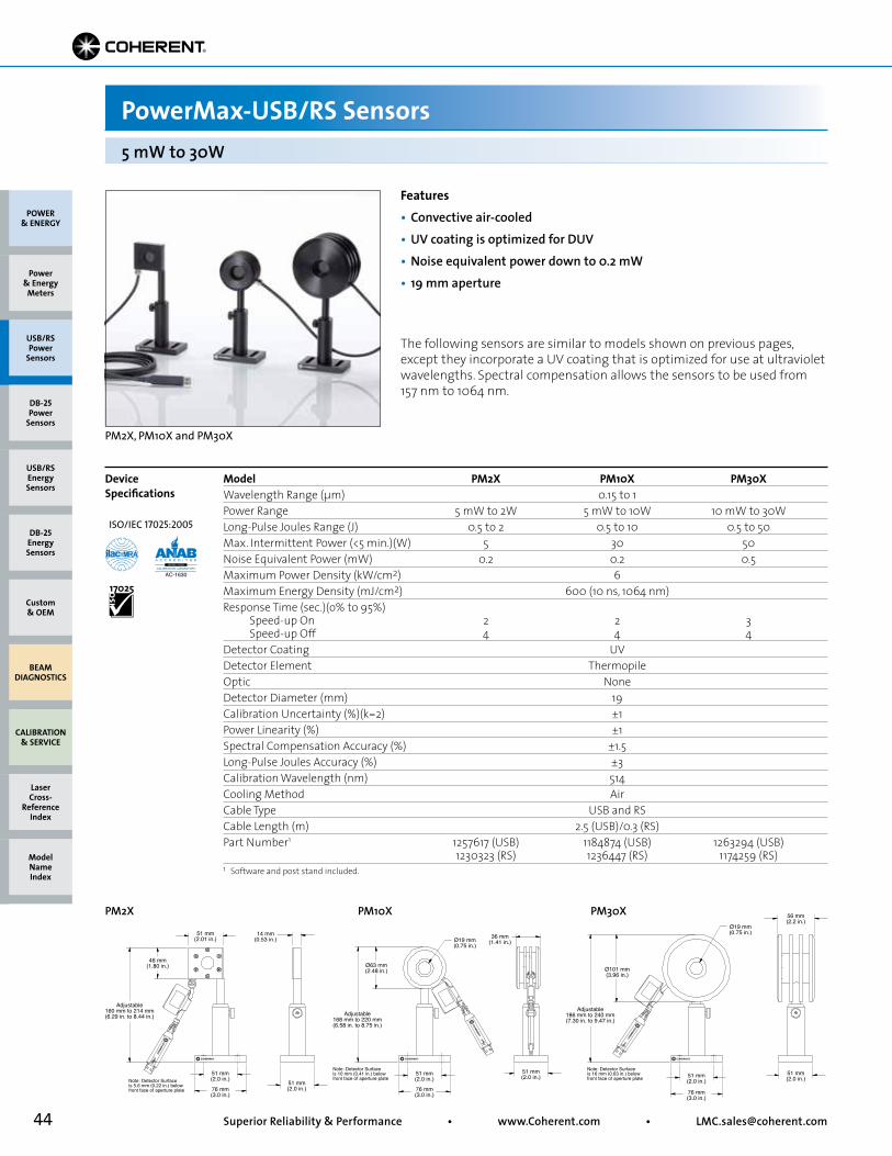
44 Superior Reliability & Performance • www.Coherent.com • [email protected]
POWER & ENERGY
Custom & OEM
BEAM DIAGNOSTICS
CALIBRATION & SERVICE
Power & Energy
Meters
Laser Cross-
Reference Index
Model Name Index
DB-25Energy Sensors
USB/RSEnergy Sensors
DB-25Power
Sensors
USB/RSPower
Sensors
51 mm(2.0 in.)
56 mm(2.2 in.)
Ø19 mm(0.75 in.)
Ø101 mm(3.96 in.)
Adjustable186 mm to 240 mm(7.30 in. to 9.47 in.)
51 mm(2.0 in.)
76 mm(3.0 in.)
Note: Detector Surfaceis 16 mm (0.63 in.) belowfront face of aperture plate
Model PM2X PM10X PM30XWavelength Range (µm) 0.15 to 1Power Range 5 mW to 2W 5 mW to 10W 10 mW to 30WLong-Pulse Joules Range (J) 0.5 to 2 0.5 to 10 0.5 to 50Max. Intermittent Power (<5 min.)(W) 5 30 50Noise Equivalent Power (mW) 0.2 0.2 0.5Maximum Power Density (kW/cm2) 6Maximum Energy Density (mJ/cm2) 600 (10 ns, 1064 nm)Response Time (sec.)(o% to 95%) Speed-up On 2 2 3 Speed-up Off 4 4 4Detector Coating UVDetector Element ThermopileOptic NoneDetector Diameter (mm) 19Calibration Uncertainty (%)(k=2) ±1Power Linearity (%) ±1Spectral Compensation Accuracy (%) ±1.5Long-Pulse Joules Accuracy (%) ±3Calibration Wavelength (nm) 514Cooling Method AirCable Type USB and RSCable Length (m) 2.5 (USB)/0.3 (RS)Part Number1 1257617 (USB) 1184874 (USB) 1263294 (USB) 1230323 (RS) 1236447 (RS) 1174259 (RS)1 Software and post stand included.
Features• Convective air-cooled• UV coating is optimized for DUV• Noise equivalent power down to 0.2 mW• 19 mm aperture
PM2X, PM10X and PM30X
The following sensors are similar to models shown on previous pages, except they incorporate a UV coating that is optimized for use at ultraviolet wavelengths. Spectral compensation allows the sensors to be used from 157 nm to 1064 nm.
Device Specifications
PM2X PM10X PM30X
5 mW to 30W
PowerMax-USB/RS Sensors
51 mm(2.0 in.)
36 mm(1.41 in.)Ø19 mm
(0.75 in.)
Ø63 mm(2.48 in.)
Adjustable168 mm to 220 mm(6.58 in. to 8.75 in.)
51 mm(2.0 in.)
76 mm(3.0 in.)
Note: Detector Surfaceis 10 mm (0.41 in.) belowfront face of aperture plate
51 mm(2.0 in.)
14 mm(0.53 in.)
51 mm(2.01 in.)
46 mm(1.80 in.)
Adjustable160 mm to 214 mm(6.29 in. to 8.44 in.)
51 mm(2.0 in.)76 mm
(3.0 in.)
Note: Detector Surfaceis 5.6 mm (0.22 in.) belowfront face of aperture plate
ISO/IEC 17025:2005

45• Toll Free: (800) 343-4912 • Tel: (408) 764-4042 • Fax: (503) 454-5727
PowerMax-USB/RS Sensors
Model PM10-19C PM100-19C PM150-19C PM150-50CWavelength Range (µm) 0.19 to 11 Power Range (water-cooled) 10 mW to 10W 300 mW to 100W 300 mW to 150W 300 mW to 150W Max. Intermittent Power (W)(<5 min.) 5 (air-cooled) 100 20 (air-cooled) 80 (air-cooled)Long-Pulse Joules (J) 0.5 to 10 1 to 100 1 to 150 1 to 150Noise Equivalent Power (mW) 0.2 1 1 1Maximum Power Density (kW/cm2) 6 Maximum Energy Density (mJ/cm2) 600 (10 ns, 1064 nm) Response Time (sec.)(o% to 95%) Speed-up On 2 2 2 3 Speed-up Off 4 4 4 12Detector Coating Broadband Detector Element Thermopile Optic None Detector Diameter (mm) 19 19 19 50Calibration Uncertainty (%)(k=2) ±2 Power Linearity (%) ±1 Spectral Compensation Accuracy (%) ±1.5 Long-Pulse Joules Accuracy (%) ±3 Calibration Wavelength (nm) 10,600 Cooling Method Water/Air (intermittent)Cable Type USB and RS Cable Length (m) 2.5 (USB)/0.3 (RS) Part Number 1168344 (USB) 1288940 (USB) 1168346 (USB) 1168348 (USB)** 1168345 (RS) 1168347 (RS) 1168349 (RS)
Device Specifications
10 mW to 150W
Features• Spectrally flat from 0.19 µm to 11 µm• Noise equivalent 0.2 mW to 1 mW• 19 mm and 50 mm apertures
The compact sensors must be water-cooled in order to achieve their full power specification during continuous operation. They can also be mount-ed to a heat sink or used standalone for intermittent use without water-cooling. Tap or distilled cooling water is recommended at a flow rate of 0.2 gallons per minute with these sensors – DI water can not be used. They are also very useful for air-cooled energy measurement of long-pulse (>1 ms) lasers using the long-pulsed Joules mode. See page 50 for RS model power supply accessory. Water fittings are included. For 150W air-cooled choose the PM150-50 sensor.
51 mm(2.0 in.)
51 mm(2.0 in.)
Ø19 mm(0.75 in.) 30 mm
(1.17 in.)
+5VDCPower Input
51 mm(2.0 in.)
Adjustable165 mm to 220 mm(6.5 in. to 8.66 in.)
51 mm(2.0 in.)
76 mm(3.0 in.)
Note: Detector Surfaceis 5.56 mm (0.22 in.) belowfront face of aperture plate
51 mm(2.0 in.)
89 mm(3.5 in.)
Ø50 mm(1.97 in.) 31 mm
(1.23 in.)
89 mm(3.5 in.)
Adjustable203 mm to 257 mm(8.0 in. to 10.12 in.)
51 mm(2.0 in.)
76 mm(3.0 in.)
Note: Detector Surfaceis 7.14 mm (0.28 in.) belowfront face of aperture plate
+5VDCPower Input
PM10-19C/PM150-19C(shown with PowerMax-RS cable)
PM150-50C (shown with PowerMax-RS cable)
PM10-19C, PM150-50C, PM150-19C and PM100-19C
** C24 Quick Ship program: eligible for next business day shipment.
POWER & ENERGY
Custom & OEM
BEAM DIAGNOSTICS
CALIBRATION & SERVICE
Power & Energy
Meters
Laser Cross-
Reference Index
Model Name Index
DB-25Energy Sensors
USB/RSEnergy Sensors
DB-25Power
Sensors
USB/RSPower
Sensors
ISO/IEC 17025:2005
**
PM100-19C
1/4-20 UNCFemale MountingThreads
51 mm(2.0 in.)
51 mm(2.0 in.)
76 mm(3.0 in.)
89 mm(3.5 in.)
89 mm(3.5 in.)
Ø19 mm(0.75 in.)
31 mm(1.23 in.)
Note: Detector Surfaceis 7.2 mm (0.28 in.) belowfront face of aperture plate
Adjustable189-259 mm
(7.44-10.2 in.)

46 Superior Reliability & Performance • www.Coherent.com • [email protected]
PowerMax-USB/RS Sensors
Unlike the PowerMax-USB that is powered through a PC’s USB 2.0 connection, the PowerMax-RS sensors must powered externally with a +5 VDC power source. An external power supply may be plugged into the 6 mm barrel receptacle, or alternatively, for custom OEM installations power may be provided on Pin 1 through the DE-9 connector. Additional information concerning integration of the OEM thermopiles, including detailed housing drawings, can be found below.
PowerMax-RS InformationPC Interface: RS-232Connector: DE-9 femaleCable length: 300 mm. Use standard RS-232 cable to connect device to PC.Communication: Pin 2 – Receive Data; Pin 3 – Transmit Data; Pin 5 – Signal GroundRequired Power: +5 VDC ±5% with less than 100 mV RMS noiseCurrent draw: <300 mAPower input connector: 6 mm barrel with 2 mm pin, center positivePower supply: Optional equipment, order #1105557 for UL and PSE certified power supply with power cord.Alternate OEM power input: +5 VDC on Pin 1; Pin 5 – Ground (shared with Signal Ground)
OEM Thermopiles Overview
PM150-50C and PM150-19C
Mounting Hole Locations PM10-19C/PM150-19C
PM150-50C
6-32 UNC-2B5 mm (0.2 in.)Deep Mounting Hole
6-32 UNC-2B5 mm (0.2 in.)Deep Mounting Hole
1/4-20 UNC-2B7 mm (0.275 in.)Deep Mounting Hole
50.8 mm(2.0 in.)Square
20.2 mm (0.8 in.)
15.2 mm (0.6 in.)
17.8 mm (0.7 in.)
7.6 mm (0.3 in.)
30.5 mm(1.2 in.)
41.3 mm(1.63 in.)
41.3 mm (1.63 in.)
4.75 mm (0.19 in.)
4.75 mm (0.19 in.)
1/4-20 UNC-2B12.7 mm (0.5 in.)Deep Mounting Hole
6-32 UNC-2B6.3 mm (0.25 in.)Deep Mounting Hole
6-32 UNC-2B5.1 mm (0.2 in.)Deep Mounting Hole
88.9 mm(3.5 in.)Square
21.2 mm (0.84 in.)17.8 mm (0.7 in.)
30.5 mm (1.2 in.) 5.6 mm (0.22 in.)
41.3 mm (1.63 in.)
23.8 mm (0.94 in.)
23.8 mm(0.94 in.)
41.3 mm (1.63 in.)
POWER & ENERGY
Custom & OEM
BEAM DIAGNOSTICS
CALIBRATION & SERVICE
Power & Energy
Meters
Laser Cross-
Reference Index
Model Name Index
DB-25Energy Sensors
USB/RSEnergy Sensors
DB-25Power
Sensors
USB/RSPower
Sensors
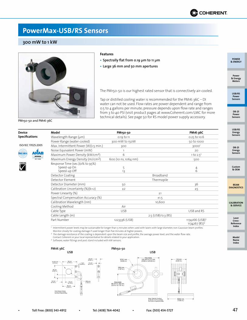
47• Toll Free: (800) 343-4912 • Tel: (408) 764-4042 • Fax: (503) 454-5727
Model PM150-50 PM1K-36C Wavelength Range (µm) 0.19 to 11 0.25 to 10.6Power Range (water-cooled) 300 mW to 150W 50 to 1000Max. Intermittent Power (W)(<5 min.) 300 30001
Noise Equivalent Power (mW) 1 20Maximum Power Density (kW/cm2) 6 1 to 2.52
Maximum Energy Density (mJ/cm2) 600 (10 ns, 1064 nm) 500Response Time (sec.)(o% to 95%) Speed-up On 5 4 Speed-up Off 13 6Detector Coating Broadband Detector Element Thermopile Detector Diameter (mm) 50 36Calibration Uncertainty (%)(k=2) ±2 ±5Power Linearity (%) ±1 Spectral Compensation Accuracy (%) ±1.5 Calibration Wavelength (nm) 10,600 Cooling Method AirCable Type USB USB and RS Cable Length (m) 2.5 (USB)/0.3 (RS) Part Number 1223336 (USB) 1174266 (USB)3
1174267 (RS)3
PM150-50 USB
118 mm(4.64 in.)
Ø202 mm(7.95 in.)
Adjustable125 mm to 217 mm(4.92 in. to 8.54 in.)
Adjustable89 mm to 190 mm(3.5 in. to 7.51 in.)
Ø151 mm(5.95 in.)
Ø50 mm(1.97 in.)
Note: Detector Surfaceis 32 mm (1.27 in.) belowfront face of aperture plate
1 Intermittent power levels may be sustainable for longer than 5 minutes when used with lasers with large diameter, non-Gaussian beam profiles. Monitor closely for coating damage if used longer than five minutes at higher powers.2 The damage resistance of the coating is dependent upon the beam size and profile, the average power level, and the water flow rate. Contact Coherent or your local representative for details related to your application.2 Software, water fittings and post stand included with kW sensors.
19 mm(0.75 in.)
19 mm(0.75 in.)
83 mm(3.25 in.)
7 mm(0.28 in.)
22 mm(0.86 in.)
12 mm(0.47 in.)
96 mm(3.79 in.)
Ø36 mm(1.42 in.)
4X Ø4 mm(0.16 in.)
83 mm(3.25 in.)
Note: Detector Surfaceis 2 mm (0.08 in.) belowfront face of aperture plate
PM1K-36C USB
Features• Spectrally flat from 0.19 µm to 11 µm• Large 36 mm and 50 mm apertures
The PM150-50 is our highest rated sensor that is connectively air-cooled.
Tap or distilled cooling water is recommended for the PM1K-36C – DI water can not be used. Flow rates are power dependent and range from 0.5 to 4 gallons per minute; pressure depends upon flow rate and ranges from 3 to 40 PSI (visit product pages at www.Coherent.com/LMC for more technical details). See page 50 for RS model power supply accessory.
PM150-50 and PM1K-36C
PowerMax-USB/RS Sensors300 mW to 1 kW
POWER & ENERGY
Custom & OEM
BEAM DIAGNOSTICS
CALIBRATION & SERVICE
Power & Energy
Meters
Laser Cross-
Reference Index
Model Name Index
DB-25Energy Sensors
USB/RSEnergy Sensors
DB-25Power
Sensors
USB/RSPower
Sensors
Device Specifications
ISO/IEC 17025:2005
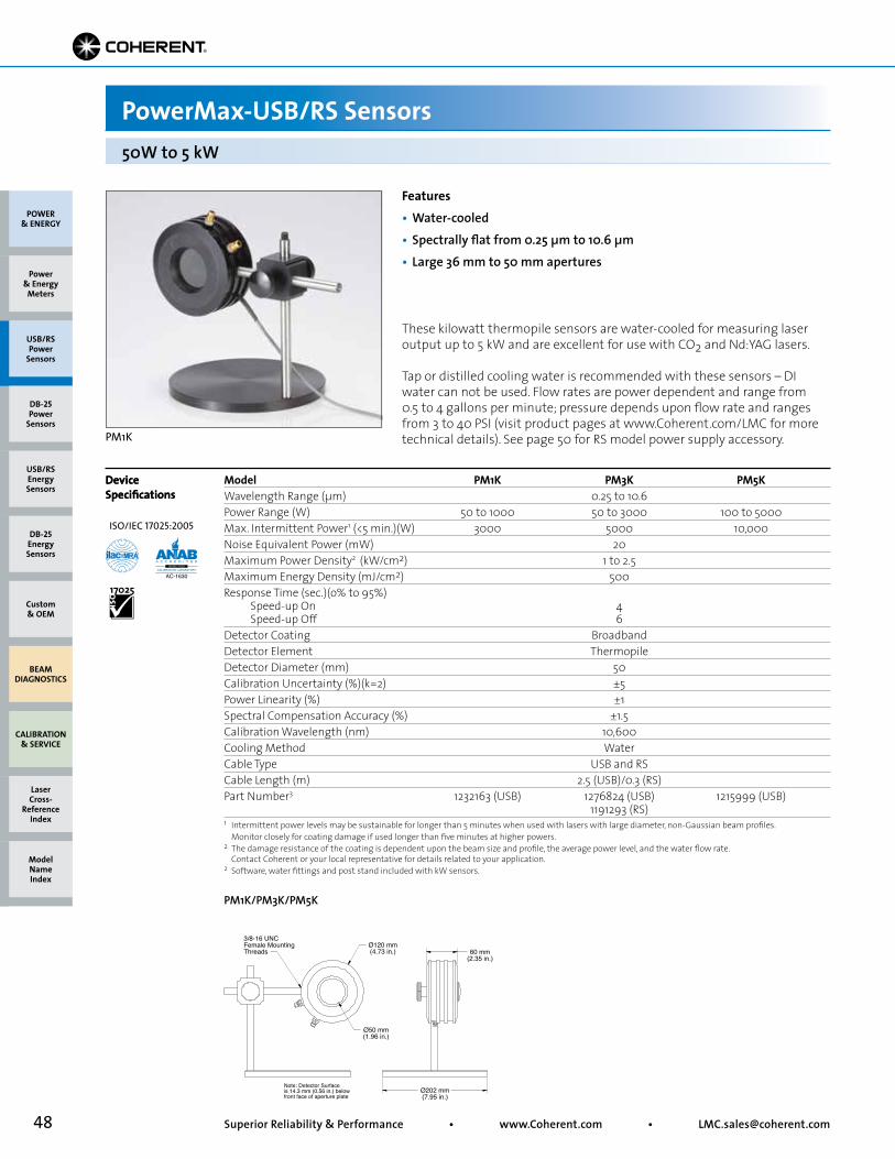
48 Superior Reliability & Performance • www.Coherent.com • [email protected]
Model PM1K PM3K PM5KWavelength Range (µm) 0.25 to 10.6Power Range (W) 50 to 1000 50 to 3000 100 to 5000Max. Intermittent Power1 (<5 min.)(W) 3000 5000 10,000Noise Equivalent Power (mW) 20Maximum Power Density2 (kW/cm2) 1 to 2.5Maximum Energy Density (mJ/cm2) 500Response Time (sec.)(o% to 95%) Speed-up On 4 Speed-up Off 6Detector Coating BroadbandDetector Element ThermopileDetector Diameter (mm) 50 Calibration Uncertainty (%)(k=2) ±5Power Linearity (%) ±1Spectral Compensation Accuracy (%) ±1.5Calibration Wavelength (nm) 10,600Cooling Method WaterCable Type USB and RSCable Length (m) 2.5 (USB)/0.3 (RS)Part Number3 1232163 (USB) 1276824 (USB) 1215999 (USB) 1191293 (RS)
Features• Water-cooled• Spectrally flat from 0.25 µm to 10.6 µm• Large 36 mm to 50 mm apertures
PM1K
These kilowatt thermopile sensors are water-cooled for measuring laser output up to 5 kW and are excellent for use with CO2 and Nd:YAG lasers.
Tap or distilled cooling water is recommended with these sensors – DI water can not be used. Flow rates are power dependent and range from 0.5 to 4 gallons per minute; pressure depends upon flow rate and ranges from 3 to 40 PSI (visit product pages at www.Coherent.com/LMC for more technical details). See page 50 for RS model power supply accessory.
Device Specifications
1 Intermittent power levels may be sustainable for longer than 5 minutes when used with lasers with large diameter, non-Gaussian beam profiles. Monitor closely for coating damage if used longer than five minutes at higher powers.2 The damage resistance of the coating is dependent upon the beam size and profile, the average power level, and the water flow rate. Contact Coherent or your local representative for details related to your application.2 Software, water fittings and post stand included with kW sensors.
50W to 5 kW
PowerMax-USB/RS Sensors
PM1K/PM3K/PM5K
3/8-16 UNCFemale MountingThreads
Ø120 mm(4.73 in.) 60 mm
(2.35 in.)
Ø50 mm(1.96 in.)
Ø202 mm(7.95 in.)
Note: Detector Surfaceis 14.3 mm (0.56 in.) belowfront face of aperture plate
Device Specifications
POWER & ENERGY
Custom & OEM
BEAM DIAGNOSTICS
CALIBRATION & SERVICE
Power & Energy
Meters
Laser Cross-
Reference Index
Model Name Index
DB-25Energy Sensors
USB/RSEnergy Sensors
DB-25Power
Sensors
USB/RSPower
Sensors
ISO/IEC 17025:2005
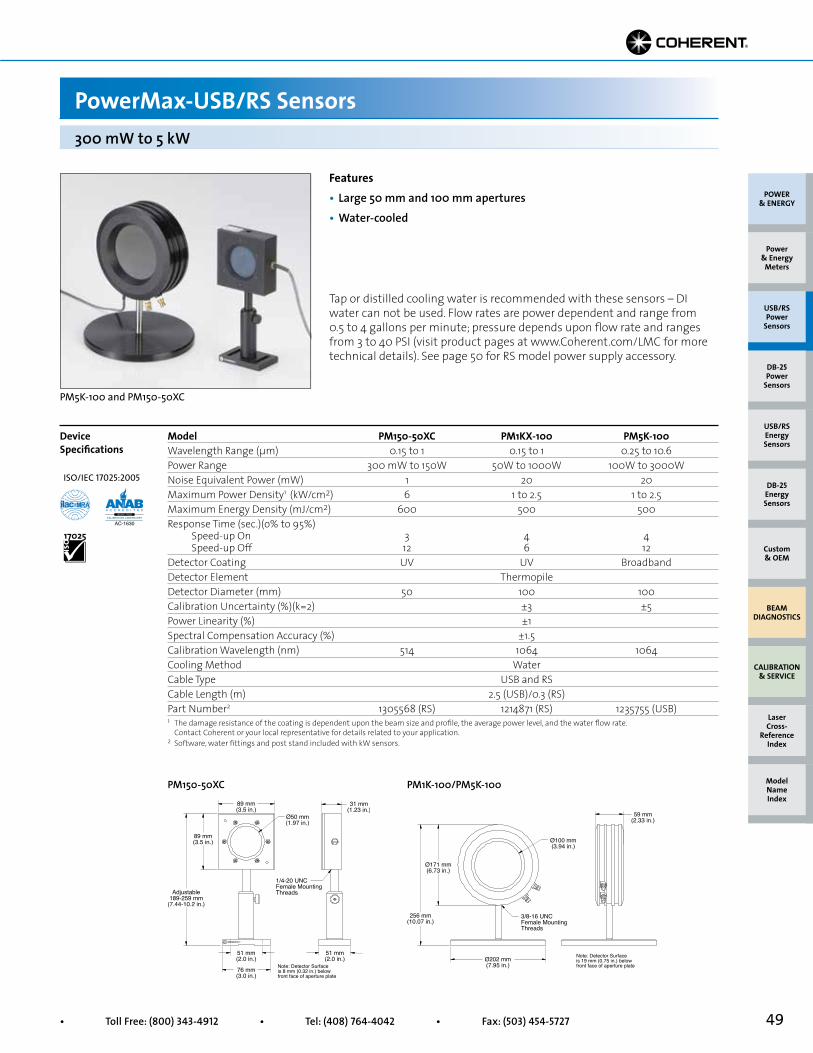
49• Toll Free: (800) 343-4912 • Tel: (408) 764-4042 • Fax: (503) 454-5727
Device Specifications
Model PM150-50XC PM1KX-100 PM5K-100 Wavelength Range (µm) 0.15 to 1 0.15 to 1 0.25 to 10.6Power Range 300 mW to 150W 50W to 1000W 100W to 3000WNoise Equivalent Power (mW) 1 20 20Maximum Power Density1 (kW/cm2) 6 1 to 2.5 1 to 2.5Maximum Energy Density (mJ/cm2) 600 500 500Response Time (sec.)(o% to 95%) Speed-up On 3 4 4 Speed-up Off 12 6 12Detector Coating UV UV BroadbandDetector Element ThermopileDetector Diameter (mm) 50 100 100Calibration Uncertainty (%)(k=2) ±3 ±5Power Linearity (%) ±1Spectral Compensation Accuracy (%) ±1.5Calibration Wavelength (nm) 514 1064 1064Cooling Method WaterCable Type USB and RSCable Length (m) 2.5 (USB)/0.3 (RS)Part Number2 1305568 (RS) 1214871 (RS) 1235755 (USB)
Features• Large 50 mm and 100 mm apertures • Water-cooled
Tap or distilled cooling water is recommended with these sensors – DI water can not be used. Flow rates are power dependent and range from 0.5 to 4 gallons per minute; pressure depends upon flow rate and ranges from 3 to 40 PSI (visit product pages at www.Coherent.com/LMC for more technical details). See page 50 for RS model power supply accessory.
PM5K-100 and PM150-50XC
PowerMax-USB/RS Sensors300 mW to 5 kW
ISO/IEC 17025:2005
POWER & ENERGY
Custom & OEM
BEAM DIAGNOSTICS
CALIBRATION & SERVICE
Power & Energy
Meters
Laser Cross-
Reference Index
Model Name Index
DB-25Energy Sensors
USB/RSEnergy Sensors
DB-25Power
Sensors
USB/RSPower
Sensors
1 The damage resistance of the coating is dependent upon the beam size and profile, the average power level, and the water flow rate. Contact Coherent or your local representative for details related to your application.2 Software, water fittings and post stand included with kW sensors.
PM1K-100/PM5K-100
3/8-16 UNCFemale MountingThreads
256 mm(10.07 in.)
59 mm(2.33 in.)
Ø171 mm(6.73 in.)
Ø100 mm(3.94 in.)
Ø202 mm(7.95 in.)
Note: Detector Surfaceis 19 mm (0.75 in.) belowfront face of aperture plate
1/4-20 UNCFemale MountingThreadsAdjustable
189-259 mm(7.44-10.2 in.)
Ø50 mm(1.97 in.)
89 mm(3.5 in.)
89 mm(3.5 in.)
31 mm(1.23 in.)
51 mm(2.0 in.)
51 mm(2.0 in.)
76 mm(3.0 in.)
Note: Detector Surfaceis 8 mm (0.32 in.) belowfront face of aperture plate
PM150-50XC
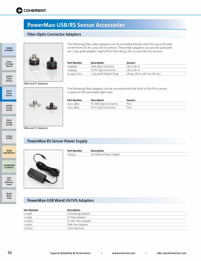
50 Superior Reliability & Performance • www.Coherent.com • [email protected]
POWER & ENERGY
Custom & OEM
BEAM DIAGNOSTICS
CALIBRATION & SERVICE
Power & Energy
Meters
Laser Cross-
Reference Index
Model Name Index
DB-25Energy Sensors
USB/RSEnergy Sensors
DB-25Power
Sensors
USB/RSPower
Sensors
The following fiber-optic adapters can be mounted directly onto the 3/4-32 threads on the front of LM-3 and LM-10 sensors. These fiber adapters can also be used with our 1.035-40M adapter ring to fit on the LM-45, LM-20, and LM-200 sensors.
The following fiber adapters can be mounted onto the front of the PS10 sensor in place of the removable light tube.
Part Number Description Sensors0012-3860 PS-SMA-Type Connector PS100012-3863 PS-FC-Type Connector PS10
Part Number Description Sensors1098589 SMA-Type Connector LM-3, LM-101098339 FC/PC-Type Connector LM-3, LM-1033-9432-000 1.035-40M Adapter Ring LM-45, LM-20, LM-100, LM-200
Fiber-Optic Connector Adapters
PowerMax-USB/RS Sensor Accessories
Part Number Description1105557 5V External Power Supply
PowerMax-RS Sensor Power Supply
SMA and FC Adapters
SMA and FC Adapters
Part Number Description1211488 Collimating Adapter1211489 FC Fiber Adapter1220619 FC-APC Fiber Adapter1220621 SMA Fiber Adapter1220622 7 mm Aperture
PowerMax-USB Wand UV/VIS Adapters
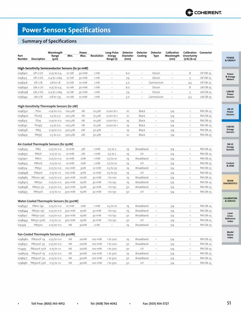
51• Toll Free: (800) 343-4912 • Tel: (408) 764-4042 • Fax: (503) 454-5727
Summary of Specifications
Power Sensors Specifications
Wavelength Power Long-Pulse Detector Detector Detector Calibration Calibration ConnectorPart Range Min. Max. Resolution Energy Diameter Coating Type Wavelength Uncertainty Number Description (µm) Range (J) (mm) (nm) (±%) (k=2)
High-Sensitivity Semiconductor Sensors (to 50 mW)1098401 OP-2 UV 0.25 to 0.4 10 nW 30 mW 1 nW – 6.0 – Silicon – 8 OP DB-25
1098313 OP-2 VIS 0.4 to 1.064 10 nW 30 mW 1 nW – 7.9 – Silicon – 5 OP DB-25
1098416 OP-2 IR 0.8 to 1.8 10 nW 10 mW 1 nW – 5.0 – Germanium – 4.5 OP DB-25
1098390 LM-2 UV 0.25 to 0.4 10 nW 30 mW 1 nW – 6.0 – Silicon – 8 LM DB-25
1098298 LM-2 VIS 0.4 to 1.064 10 nW 30 mW 1 nW – 7.9 – Silicon – 5 LM DB-25
1098342 LM-2 IR 0.8 to 1.55 10 nW 10 mW 1 nW – 5.0 – Germanium – 4.5 LM DB-25
High-Sensitivity Thermopile Sensors (to 2W)1098350 PS10 0.19 to 11.0 100 µW 1W 10 µW 0.001 to 1 10 Black – 514 1 PM DB-25
1098400 PS10Q 0.3 to 2.0 100 µW 1W 10 µW 0.001 to 1 10 Black – 514 1 PM DB-25
1098413 PS19 0.19 to 11.0 100 µW 1W 10 µW 0.001 to 1 19 Black – 514 1 PM DB-25
1098341 PS19Q 0.3 to 2.0 100 µW 1W 10 µW 0.001 to 1 19 Black – 514 1 PM DB-25
1098336 PM3 0.19 to 11.0 500 µW 2W 50 µW – 19 Black – 514 1 PM DB-25
1098419 PM3Q 0.3 to 2.0 500 µW 2W 50 µW – 10 Black – 514 1 PM DB-25
Air-Cooled Thermopile Sensors (to 150W)1098329 PM2 0.25 to 11.0 10 mW 2W 1 mW 0.5 to 2 19 Broadband – 514 1 PM DB-25
1098457 PM2X 0.15 to 1.0 10 mW 2W 1 mW 0.5 to 2 19 UV – 514 1 PM DB-25
1097901 PM10 0.25 to 11.0 10 mW 10W 1 mW 0.5 to 10 19 Broadband – 514 1 PM DB-25
1098423 PM10X 0.15 to 1.0 10 mW 10W 1 mW 0.5 to 10 19 UV – 514 1 PM DB-25
1098314 PM30 0.25 to 11.0 100 mW 30W 10 mW 0.5 to 50 19 Broadband – 514 1 PM DB-25
1098498 PM30X 0.15 to 1.0 100 mW 30W 10 mW 0.5 to 50 19 UV – 514 1 PM DB-25
1098483 PM100-19C 0.25 to 11.0 300 mW 100W 30 mW 1 to 100 19 Broadband – 514 1 PM DB-25
1098407 PM150 0.25 to 11.0 300 mW 150W 30 mW 1 to 150 19 Broadband – 514 1 PM DB-25
1098398 PM150-50 0.25 to 11.0 300 mW 150W 30 mW 1 to 150 50 Broadband – 514 1 PM DB-25
1098455 PM150X 0.15 to 1.0 300 mW 150W 30 mW 1 to 150 50 UV – 514 1 PM DB-25
Water-Cooled Thermopile Sensors (to 300W)1098397 PM10-19C 0.25 to 11.0 10 mW 10W 1 mW 0.5 to 10 19 Broadband – 514 1 PM DB-25
1098444 PM150-19C 0.25 to 11.0 300 mW 150W 30 mW 1 to 150 19 Broadband – 514 1 PM DB-25
1098412 PM150-50C 0.25 to 11.0 300 mW 150W 30 mW 1 to 150 50 Broadband – 514 1 PM DB-25
1098443 PM150-50XC 0.15 to 1.0 300 mW 150W 30 mW 1 to 150 50 UV – 514 1 PM DB-25
1141474 PM300 0.25 to 11.0 1W 300W 0.1W – 19 Broadband – 514 1 PM DB-25
Fan-Cooled Thermopile Sensors (to 300W)1098480 PM200F-19 0.25 to 11.0 1W 200W 100 mW 1 to 200 19 Broadband – 514 1 PM DB-25
1098472 PM200F-50 0.25 to 11.0 1W 200W 100 mW 1 to 200 50 Broadband – 514 1 PM DB-25
1113493 PM200F-50X 0.15 to 1.0 1W 200W 100 mW 1 to 200 50 UV – 514 1 PM DB-25
1098509 PM300F-19 0.25 to 11.0 1W 300W 100 mW 1 to 300 19 Broadband – 514 1 PM DB-25
1098417 PM300F-50 0.25 to 11.0 1W 300W 100 mW 1 to 300 50 Broadband – 514 1 PM DB-25
1098481 PM300F-50X 0.15 to 1.0 1W 300W 100 mW 1 to 300 50 UV – 514 1 PM DB-25
POWER & ENERGY
Custom & OEM
BEAM DIAGNOSTICS
CALIBRATION & SERVICE
Power & Energy
Meters
Laser Cross-
Reference Index
Model Name Index
DB-25Energy Sensors
USB/RSEnergy Sensors
DB-25Power
Sensors
USB/RSPower
Sensors
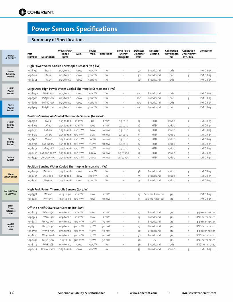
52 Superior Reliability & Performance • www.Coherent.com • [email protected]
POWER & ENERGY
Custom & OEM
BEAM DIAGNOSTICS
CALIBRATION & SERVICE
Power & Energy
Meters
Laser Cross-
Reference Index
Model Name Index
DB-25Energy Sensors
USB/RSEnergy Sensors
DB-25Power
Sensors
USB/RSPower
Sensors
Summary of Specifications
Power Sensors Specifications
Wavelength Power Long-Pulse Detector Detector Calibration Calibration ConnectorPart Range Min. Max. Resolution Energy Diameter Coating Wavelength Uncertainty Number Description (µm) Range (J) (mm) (nm) (±%)(k=2)
High Power Water-Cooled Thermopile Sensors (to 5 kW)1098392 PM1K 0.25 to 11.0 100W 1000W 1W – 50 Broadband 1064 3 PM DB-25
1098462 PM3K 0.25 to 11.0 100W 3000W 1W – 50 Broadband 1064 3 PM DB-25
1098454 PM5K 0.25 to 11.0 100W 5000W 1W – 50 Broadband 1064 3 PM DB-25
Large Area High Power Water-Cooled Thermopile Sensors (to 5 kW)1098490 PM1K-100 0.25 to 11.0 100W 1000W 1W – 100 Broadband 1064 3 PM DB-25
1098506 PM3K-100 0.25 to 11.0 100W 3000W 1W – 100 Broadband 1064 3 PM DB-25
1098461 PM5K-100 0.25 to 11.0 100W 5000W 1W – 100 Broadband 1064 3 PM DB-25
1098505 PM5K-200 0.25 to 11.0 100W 5000W 1W – 200 Broadband 1064 3 PM DB-25
Position-Sensing Air-Cooled Thermopile Sensors (to 200W)1098328 LM-3 0.25 to 10.6 10 mW 3W 1 mW 0.5 to 10 19 HTD 10600 2 LM DB-25
1098304 LM-10 0.25 to 10.6 10 mW 10W 1 mW 0.5 to 10 16 HTD 10600 2 LM DB-25
1098456 LM-20 0.25 to 10.6 100 mW 20W 10 mW 0.5 to 10 19 HTD 10600 2 LM DB-25
1098320 LM-45 0.25 to 10.6 100 mW 45W 10 mW 0.5 to 10 19 HTD 10600 2 LM DB-25
1098346 LM-100 0.25 to 10.6 100 mW 100W 10 mW 0.5 to 10 19 HTD 10600 2 LM DB-25
1098394 LM-150 FS 0.25 to 10.6 100 mW 150W 10 mW 0.5 to 10 19 HTD 10600 5 LM DB-25
1098452 LM-150 LS 0.25 to 10.6 100 mW 150W 10 mW 0.5 to 10 19 HTD 10600 5 LM DB-25
1098450 LM-200 220V 0.25 to 10.6 100 mW 200W 10 mW 0.5 to 100 19 HTD 10600 5 LM DB-25
1098440 LM-200 110V 0.25 to 10.6 100 mW 200W 10 mW 0.5 to 100 19 HTD 10600 5 LM DB-25
Position-Sensing Water-Cooled Thermopile Sensors (to 5 kW)1098409 LM-1000 0.25 to 10.6 100W 1000W 1W – 38 Broadband 10600 5 LM DB-25
1098437 LM-2500 0.25 to 10.6 100W 2500W 1W – 55 Broadband 10600 5 LM DB-25
1098421 LM-5000 0.25 to 10.6 100W 5000W 1W – 55 Broadband 10600 5 LM DB-25
High Peak Power Thermopile Sensors (to 30W)1098338 PM10V1 0.25 to 3.0 10 mW 10W 1 mW – 19 Volume Absorber 514 1 PM DB-25
1098429 PM30V1 0.25 to 3.0 100 mW 30W 10 mW – 19 Volume Absorber 514 1 PM DB-25
Off-the-Shelf OEM Power Sensors (to 1 kW)1098334 PM10-19A 0.19 to 11.0 10 mW 10W 1 mW – 19 Broadband 514 1 4-pin connector
1098343 PM10-19B 0.19 to 11.0 10 mW 10W 1 mW – 19 Broadband 514 1 BNC-terminated
1098418 PM150-19A 0.19 to 11.0 300 mW 150W 30 mW – 19 Broadband 514 1 4-pin connector
1098321 PM150-19B 0.19 to 11.0 300 mW 150W 30 mW – 19 Broadband 514 1 BNC-terminated
1098510 PM150-50A 0.19 to 11.0 300 mW 150W 30 mW – 50 Broadband 514 1 4-pin connector
1098415 PM150-50B 0.19 to 11.0 300 mW 150W 30 mW – 50 Broadband 514 1 BNC-terminated
1098441 PM150-50XB 0.15 to 1.0 300 mW 150W 30 mW – 50 UV 514 1 BNC-terminated
1098333 PM1K-36B 0.19 to 11.0 100W 1000W 1W – 36 Broadband 1064 3 BNC-terminated
1098427 BeamFinder 0.25 to 10.6 100W 1000W 1W – 35 Broadband 10600 5 LM DB-25
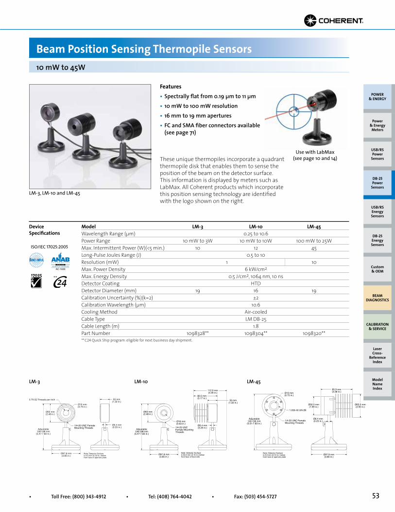
53• Toll Free: (800) 343-4912 • Tel: (408) 764-4042 • Fax: (503) 454-5727
LM-3 LM-10 LM-45
Use with LabMax (see page 10 and 14)
Features• Spectrally flat from 0.19 µm to 11 µm• 10 mW to 100 mW resolution• 16 mm to 19 mm apertures• FC and SMA fiber connectors available (see page 71)
LM-3, LM-10 and LM-45
These unique thermopiles incorporate a quadrant thermopile disk that enables them to sense the position of the beam on the detector surface. This information is displayed by meters such as LabMax. All Coherent products which incorporate this position sensing technology are identified with the logo shown on the right.
Model LM-3 LM-10 LM-45Wavelength Range (µm) 0.25 to 10.6Power Range 10 mW to 3W 10 mW to 10W 100 mW to 25WMax. Intermittent Power (W)(<5 min.) 10 12 45Long-Pulse Joules Range (J) 0.5 to 10Resolution (mW) 1 10Max. Power Density 6 kW/cm2
Max. Energy Density 0.5 J/cm2, 1064 nm, 10 nsDetector Coating HTDDetector Diameter (mm) 19 16 19Calibration Uncertainty (%)(k=2) ±2Calibration Wavelength (µm) 10.6Cooling Method Air-cooledCable Type LM DB-25Cable Length (m) 1.8Part Number 1098328** 1098304** 1098320**
Device Specifications
10 mW to 45W
Beam Position Sensing Thermopile Sensors
Ø97.8 mm(3.85 in.)
Ø19 mm(0.75 in.)
Ø63 mm(2.48 in.)
Ø6.4 mm(0.25 in.)
33 mm(1.30 in.)
0.75-32 Threads per inch
1/4-20 UNC FemaleMounting ThreadsAdjustable
139-198 mm(5.47-7.80 in.)
Note: Detector Surfaceis 8.5 mm (0.33 in.) belowfront face of aperture plate
Ø97.8 mm(3.85 in.)
Adjustable139-198 mm
(5.47-7.80 in.)
Ø63 mm(2.48 in.)
Ø16 mm(0.63 in.)
1/4-20 UNCFemale MountingThreads
Ø6.4 mm(0.25 in.)
33 mm(1.30 in.)
112.9 mm(4.45 in.)
80.5 mm(3.17 in.)
Note: Detector Surfaceis 54.6 mm (2.15 in.) belowfront face of heat sink
Ø97.8 mm(3.85 in.)
Ø19 mm(0.75 in.)
Ø50.5 mm(1.99 in.)
85.9 mm(3.38 in.)
Ø63.5 mm(2.50 in.)
Ø6.4 mm(0.25 in.)
1.035-40 UN-2B
1/4-20 UNC FemaleMounting Threads
Adjustable140-199 mm
(5.51-7.83 in.)
Note: Detector Surfaceis 8.6 mm (0.34 in.) belowfront face of aperture plate
POWER & ENERGY
Custom & OEM
BEAM DIAGNOSTICS
CALIBRATION & SERVICE
Power & Energy
Meters
Laser Cross-
Reference Index
Model Name Index
DB-25Energy Sensors
USB/RSEnergy Sensors
DB-25Power
Sensors
USB/RSPower
Sensors
** C24 Quick Ship program: eligible for next business day shipment.
ISO/IEC 17025:2005
**
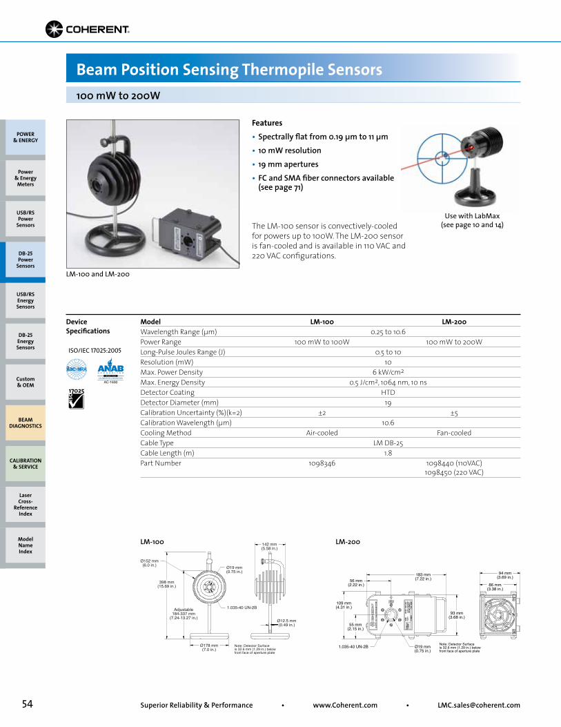
54 Superior Reliability & Performance • www.Coherent.com • [email protected]
POWER & ENERGY
Custom & OEM
BEAM DIAGNOSTICS
CALIBRATION & SERVICE
Power & Energy
Meters
Laser Cross-
Reference Index
Model Name Index
DB-25Energy Sensors
USB/RSEnergy Sensors
DB-25Power
Sensors
USB/RSPower
SensorsUse with LabMax
(see page 10 and 14)
Features• Spectrally flat from 0.19 µm to 11 µm• 10 mW resolution• 19 mm apertures• FC and SMA fiber connectors available (see page 71)
LM-100 and LM-200
The LM-100 sensor is convectively-cooled for powers up to 100W. The LM-200 sensor is fan-cooled and is available in 110 VAC and 220 VAC configurations.
Model LM-100 LM-200Wavelength Range (µm) 0.25 to 10.6Power Range 100 mW to 100W 100 mW to 200WLong-Pulse Joules Range (J) 0.5 to 10Resolution (mW) 10Max. Power Density 6 kW/cm2
Max. Energy Density 0.5 J/cm2, 1064 nm, 10 nsDetector Coating HTDDetector Diameter (mm) 19Calibration Uncertainty (%)(k=2) ±2 ±5Calibration Wavelength (µm) 10.6Cooling Method Air-cooled Fan-cooledCable Type LM DB-25Cable Length (m) 1.8Part Number 1098346 1098440 (110VAC) 1098450 (220 VAC)
Device Specifications
100 mW to 200W
Beam Position Sensing Thermopile Sensors
Ø178 mm(7.0 in.)
398 mm(15.69 in.)
Ø152 mm(6.0 in.) Ø19 mm
(0.75 in.)
142 mm(5.58 in.)
Ø12.5 mm(0.49 in.)
1.035-40 UN-2BAdjustable184-337 mm
(7.24-13.27 in.)
Note: Detector Surfaceis 32.6 mm (1.29 in.) belowfront face of aperture plate
Ø19 mm(0.75 in.)
183 mm(7.22 in.)56 mm
(2.22 in.)
109 mm(4.31 in.)
55 mm(2.15 in.)
93 mm(3.68 in.)
94 mm(3.69 in.)
86 mm(3.38 in.)
1.035-40 UN-2B Note: Detector Surfaceis 32.6 mm (1.29 in.) belowfront face of aperture plate
LM-100 LM-200
ISO/IEC 17025:2005
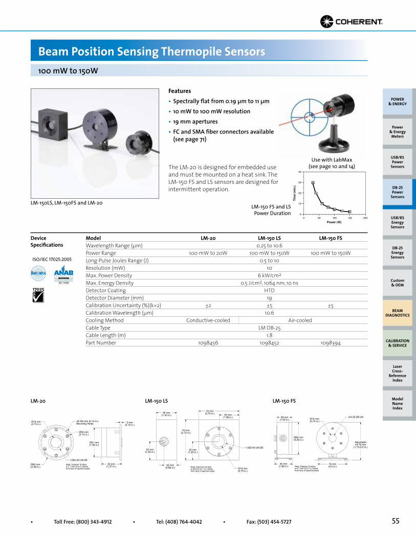
55• Toll Free: (800) 343-4912 • Tel: (408) 764-4042 • Fax: (503) 454-5727
Use with LabMax (see page 10 and 14)
00
Power (W)
Tim
e (m
in.)
10
20
30
40
50 100 150 200
LM-150 FS and LS Power Duration
Features• Spectrally flat from 0.19 µm to 11 µm• 10 mW to 100 mW resolution• 19 mm apertures• FC and SMA fiber connectors available (see page 71)
LM-150LS, LM-150FS and LM-20
Model LM-20 LM-150 LS LM-150 FSWavelength Range (µm) 0.25 to 10.6Power Range 100 mW to 20W 100 mW to 150W 100 mW to 150WLong-Pulse Joules Range (J) 0.5 to 10Resolution (mW) 10Max. Power Density 6 kW/cm2
Max. Energy Density 0.5 J/cm2, 1064 nm, 10 nsDetector Coating HTDDetector Diameter (mm) 19Calibration Uncertainty (%)(k=2) ±2 ±5 ±5Calibration Wavelength (µm) 10.6Cooling Method Conductive-cooled Air-cooledCable Type LM DB-25Cable Length (m) 1.8Part Number 1098456 1098452 1098394
Device Specifications
LM-20 LM-150 LS LM-150 FS
100 mW to 150W
Beam Position Sensing Thermopile Sensors
The LM-20 is designed for embedded use and must be mounted on a heat sink. The LM-150 FS and LS sensors are designed for intermittent operation.
35 mm(1.37 in.)
3 mm(0.10 in.)
Ø54 mm(2.12 in.)
4X Ø4 mm (0.16 in.)Mounting Holes
Ø51 mm(1.99 in.)
Ø19 mm(0.75 in.)
Ø60 mm(2.38 in.)
1.035-40 UN-2B
Note: Detector Surfaceis 7.7 mm (0.3 in.) belowfront face of aperture plate Ø19 mm
(0.75 in.)
22 mm(0.86 in.)
32 mm(1.25 in.)
36 mm(1.40 in.)
70 mm(2.75 in.) 35 mm
(1.38 in.)
32 mm(1.25 in.)
70 mm(2.75 in.)
1.035-40 UN-2B
Note: Detector Surfaceis 8.8 mm (0.7 in.) belowfront face of aperture plate
76 mm(3.0 in.)
Ø19 mm(0.75 in.)
38 mm(1.50 in.)
Ø83 mm(3.25 in.)
46 mm(1.80 in.)
3/4-32-2B UN
Adjustable44-76 mm
(1.73-3.0 in.)
Note: Detector Surfaceis 6.7 mm (0.27 in.) belowfront face of aperture plate
POWER & ENERGY
Custom & OEM
BEAM DIAGNOSTICS
CALIBRATION & SERVICE
Power & Energy
Meters
Laser Cross-
Reference Index
Model Name Index
DB-25Energy Sensors
USB/RSEnergy Sensors
DB-25Power
Sensors
USB/RSPower
Sensors
ISO/IEC 17025:2005
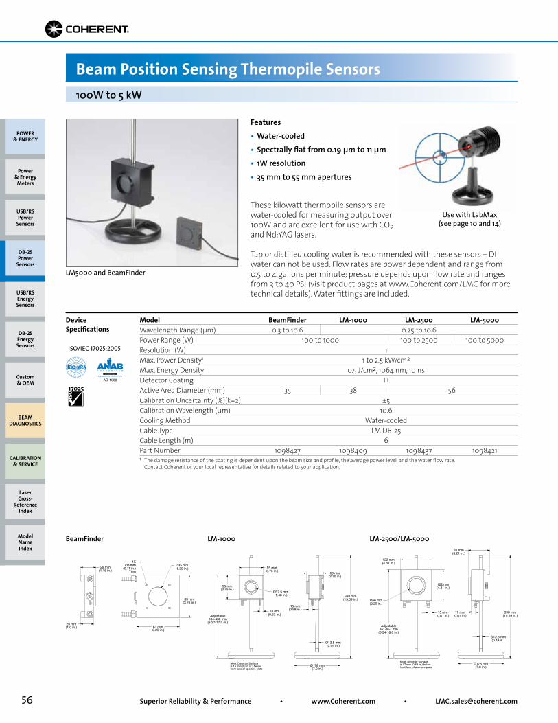
56 Superior Reliability & Performance • www.Coherent.com • [email protected]
POWER & ENERGY
Custom & OEM
BEAM DIAGNOSTICS
CALIBRATION & SERVICE
Power & Energy
Meters
Laser Cross-
Reference Index
Model Name Index
DB-25Energy Sensors
USB/RSEnergy Sensors
DB-25Power
Sensors
USB/RSPower
Sensors
Model BeamFinder LM-1000 LM-2500 LM-5000Wavelength Range (µm) 0.3 to 10.6 0.25 to 10.6Power Range (W) 100 to 1000 100 to 2500 100 to 5000Resolution (W) 1Max. Power Density1 1 to 2.5 kW/cm2
Max. Energy Density 0.5 J/cm2, 1064 nm, 10 nsDetector Coating HActive Area Diameter (mm) 35 38 56Calibration Uncertainty (%)(k=2) ±5Calibration Wavelength (µm) 10.6Cooling Method Water-cooledCable Type LM DB-25Cable Length (m) 6Part Number 1098427 1098409 1098437 1098421
Use with LabMax (see page 10 and 14)
Features• Water-cooled• Spectrally flat from 0.19 µm to 11 µm• 1W resolution• 35 mm to 55 mm apertures
LM5000 and BeamFinder
These kilowatt thermopile sensors are water-cooled for measuring output over 100W and are excellent for use with CO2 and Nd:YAG lasers.
Tap or distilled cooling water is recommended with these sensors – DI water can not be used. Flow rates are power dependent and range from 0.5 to 4 gallons per minute; pressure depends upon flow rate and ranges from 3 to 40 PSI (visit product pages at www.Coherent.com/LMC for more technical details). Water fittings are included.
Device Specifications
1 The damage resistance of the coating is dependent upon the beam size and profile, the average power level, and the water flow rate. Contact Coherent or your local representative for details related to your application.
BeamFinder LM-1000 LM-2500/LM-5000
100W to 5 kW
Beam Position Sensing Thermopile Sensors
83 mm(3.25 in.)
83 mm(3.25 in.)
Ø35 mm(1.39 in.)29 mm
(1.16 in.)
25 mm(1.0 in.)
4XØ3 mm
(0.11 in.)Thru
15 mm(0.58 in.)13 mm
(0.53 in.)
95 mm(3.75 in.)
95 mm(3.75 in.)
Adjustable134-430 mm
(5.27-17.0 in.)
398 mm(15.69 in.)
69 mm(2.70 in.)
Ø178 mm(7.0 in.)
Ø12.5 mm(0.49 in.)
Ø37.5 mm(1.48 in.)
Note: Detector Surfaceis 16 mm (0.63 in.) belowfront face of aperture plate
Adjustable161-457 mm
(6.34-18.0 in.)
Ø178 mm(7.0 in.)
15 mm(0.61 in.)
17 mm(0.67 in.)
122 mm(4.81 in.)
Ø56 mm(2.20 in.)
122 mm(4.81 in.)
81 mm(3.21 in.)
398 mm(15.69 in.)
Ø12.5 mm(0.49 in.)
Note: Detector Surfaceis 17 mm (0.69 in.) belowfront face of aperture plate
ISO/IEC 17025:2005
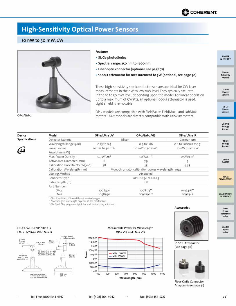
57• Toll Free: (800) 343-4912 • Tel: (408) 764-4042 • Fax: (503) 454-5727
10 nW to 50 mW, CW
High-Sensitivity Optical Power Sensors
POWER & ENERGY
Custom & OEM
BEAM DIAGNOSTICS
CALIBRATION & SERVICE
Power & Energy
Meters
Laser Cross-
Reference Index
Model Name Index
DB-25Energy Sensors
USB/RSEnergy Sensors
DB-25Power
Sensors
USB/RSPower
Sensors
Features• Si, Ge photodiodes• Spectral range: 250 nm to 1800 nm• Fiber-optic connector (optional, see page 71)• 1000:1 attenuator for measurement to 5W (optional, see page 70)
Model OP-2/LM-2 UV OP-2/LM-2 VIS OP-2/LM-2 IRDetector Material Silicon GermaniumWavelength Range (µm) 0.25 to 0.4 0.4 to 1.06 0.8 to 1.80/0.8 to 1.51
Power Range 10 nW to 30 mW 10 nW to 30 mW2 10 nW to 10 mWResolution (nW) 1Max. Power Density 0.3 W/cm2 1.0 W/cm2 0.5 W/cm2
Active Area Diameter (mm) 6 7.9 5Calibration Uncertainty (%)(k=2) ±8 ±5 ±4.5Calibration Wavelength (nm) Monochromator calibration across wavelength rangeCooling Method Air-cooledConnector Type OP DB-25/LM DB-25Cable Length (m) 1.8Part Number OP-2 1098401 1098313** 1098416** LM-2 1098390 1098298** 1098342
These high-sensitivity semiconductor sensors are ideal for CW laser measurements in the nW to low mW level. They typically saturate in the 10 to 50 mW level, depending upon the model. For linear operation up to a maximum of 5 Watts, an optional 1000:1 attenuator is used. Light shield is removable.
OP-2 models are compatible with FieldMate, FieldMaxII and LabMax meters. LM-2 models are directly compatible with LabMax meters.
Device Specifications
1 OP-2 IR and LM-2 IR have different spectral ranges.2 Power range is wavelength dependent. See chart below.** C24 Quick Ship program: eligible for next business day shipment.
1000:1 Attenuator (see page 70)
OP-2 UV/OP-2 VIS/OP-2 IRLM-2 UV/LM-2 VIS/LM-2 IR
Measurable Power vs. WavelengthOP-2 VIS and LM-2 VIS
Accessories
OP-2/LM-2
Wavelength (nm)
Pow
er
1 nW400
100 mW
10 nW
100 nW
1 µW
10 µW
100 µW
1 mW
10 mW
500 600 700 800 900 1000 1100
Min. PowerMax. Power
Adjustable108-171 mm
(4.25-6.73 in.)
R15 mm(0.6 in.)
Light Shieldis Removeable
0.75-32Threadsper inch
55 mm(2.2 in.) 20 mm
(0.8 in.)
Ø6 mm(0.3 in.)
Ø7.9 mm (0.31 in.) VISØ6.0 mm (0.24 in.) UVØ5.0 mm (0.20 in.) IR
Ø98 mm(3.9 in.)
Note: Detector Surfaceis 7.1 mm (0.28 in.) belowfront face of aperture plate
**
Fiber-Optic Connector Adapters (see page 71)
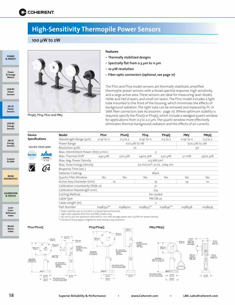
58 Superior Reliability & Performance • www.Coherent.com • [email protected]
POWER & ENERGY
Custom & OEM
BEAM DIAGNOSTICS
CALIBRATION & SERVICE
Power & Energy
Meters
Laser Cross-
Reference Index
Model Name Index
DB-25Energy Sensors
USB/RSEnergy Sensors
DB-25Power
Sensors
USB/RSPower
Sensors
Model PS102 PS10Q PS19 PS19Q PM32 PM3QWavelength Range (µm) 0.193 to 11 0.3 to 2 0.193 to 11 0.3 to 2 0.193 to 11 0.3 to 2Power Range 100 µW to 1W 500 µW to 2WResolution (µW) 10 50Max. Intermittent Power (W)(<5 min.) 3Max. Thermal Drift1 ±40 µW ±20 µW ±400 µW ±20 µW ±1 mW ±500 µWMax. Avg. Power Density 0.5 kW/cm2
Max. Pulse Energy Density 50 mJ/cm2, 10 ns , 1064 nmResponse Time (sec.) 2Detector Coating BlackQuartz Filter Window No Yes No Yes No YesActive Area Diameter (mm) 10 19 19 10Calibration Uncertainty (%)(k=2) ±1Calibration Wavelength (nm) 514Cooling Method Air-cooledCable Type PM DB-25Cable Length (m) 2Part Number 1098350** 1098400 1098413** 1098341** 1098336 10984191 Power stability over 30 minutes in a typical lab environment.2 Light tube supplied with PS10 and PM3 models only.3 190 nm to 300 nm operation restricted to <100 mW average power and <250W/cm2 power density.** C24 Quick Ship program: eligible for next business day shipment.
The PS10 and PS19 model sensors are thermally stabilized, amplified thermopile power sensors with a broad spectral response, high sensitivity, and a large active area. These sensors are ideal for measuring laser diodes, HeNe and HeCd lasers, and small ion lasers. The PS10 model includes a light tube mounted to the front of the housing, which minimizes the effects of background radiation. The light tube can be removed and replaced by FC or SMA fiber connectors (see Accessories - page 71). Where optimum stability is required, specify the PS10Q or PS19Q, which include a wedged quartz window for applications from 0.3 to 2.0 µm. The quartz window more effectively eliminates thermal background radiation and the effects of air currents.
Device Specifications
Features• Thermally stabilized designs• Spectrally flat from 0.3 µm to 11 µm• 10 µW resolution• Fiber-optic connectors (optional, see page 71)
PS19Q, PS19, PS10 and PM3
100 µW to 2W
High-Sensitivity Thermopile Power Sensors
51 mm(2.0 in.)
36 mm(1.4 in.)
PM3 only
39 mm(1.53 in.)
PM3Q only
Ø19 mm(0.75 in.)
Ø22 mm(0.89 in.)
Light TubePM3 only
74 mm(2.9 in.)
Light TubePM3 only
(removable)
Ø63 mm(2.48 in.)
Adjustable186 mm to 227 mm(6.81 in. to 8.96 in.)
51 mm(2.0 in.)
76 mm(3.0 in.)
Note: Detector Surfaceis 11 mm (0.44 in.) belowfront face of aperture plate
Adjustable198-252 mm
(7.79-9.97 in.)
Ø83.8 mm(3.3 in.)
Ø10 mm(0.39 in.)
Ø12.2 mm(0.48 in.)
76.4 mm(3.01 in.)
48.5 mm(1.91 in.)
51 mm(2.0 in.)
51 mm(2.0 in.)76 mm(3.0 in.)
2X 1/4-20 UNCFemale MountingThreads180° Apart
2X M6X1Female MountingThreads180° Apart
Light TubePS10 only
Note: Detector Surfaceis 19.0 mm (0.75 in.) belowfront face of aperture plate
2X 1/4-20 UNCFemale MountingThreads180° Apart
2X M6X1Female MountingThreads180° Apart
Adjustable197-252 mm
(7.75-9.93 in.)
Ø19 mm(0.76 in.)
Ø84 mm(3.3 in.)
48 mm(1.91 in.)
51 mm(2.0 in.)
51 mm(2.0 in.)76 mm(3.0 in.)
Note: Detector Surfaceis 19.0 mm (0.75 in.) belowfront face of aperture plate
PS19/PS19QPS10/PS10Q PM3/PM3Q
ISO/IEC 17025:2005
**
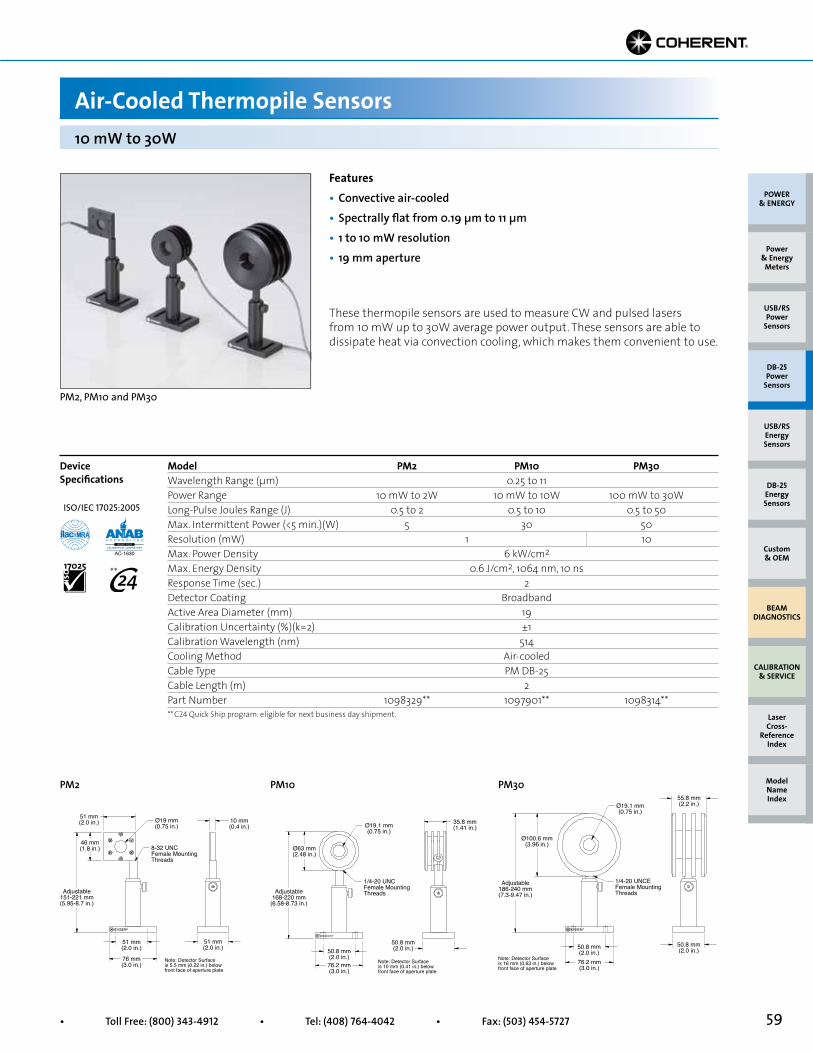
59• Toll Free: (800) 343-4912 • Tel: (408) 764-4042 • Fax: (503) 454-5727
Features• Convective air-cooled• Spectrally flat from 0.19 µm to 11 µm• 1 to 10 mW resolution• 19 mm aperture
PM2, PM10 and PM30
These thermopile sensors are used to measure CW and pulsed lasers from 10 mW up to 30W average power output. These sensors are able to dissipate heat via convection cooling, which makes them convenient to use.
Model PM2 PM10 PM30Wavelength Range (µm) 0.25 to 11Power Range 10 mW to 2W 10 mW to 10W 100 mW to 30WLong-Pulse Joules Range (J) 0.5 to 2 0.5 to 10 0.5 to 50Max. Intermittent Power (<5 min.)(W) 5 30 50Resolution (mW) 1 10Max. Power Density 6 kW/cm2
Max. Energy Density 0.6 J/cm2, 1064 nm, 10 nsResponse Time (sec.) 2Detector Coating BroadbandActive Area Diameter (mm) 19Calibration Uncertainty (%)(k=2) ±1Calibration Wavelength (nm) 514Cooling Method Air-cooledCable Type PM DB-25Cable Length (m) 2Part Number 1098329** 1097901** 1098314**
Device Specifications
PM2 PM10 PM30
10 mW to 30W
Air-Cooled Thermopile Sensors
Adjustable186-240 mm(7.3-9.47 in.)
Ø100.6 mm(3.96 in.)
Ø19.1 mm(0.75 in.)
55.8 mm(2.2 in.)
50.8 mm(2.0 in.)50.8 mm
(2.0 in.)76.2 mm(3.0 in.)
1/4-20 UNCEFemale MountingThreads
Note: Detector Surfaceis 16 mm (0.63 in.) belowfront face of aperture plate
Adjustable168-220 mm
(6.58-8.73 in.)
Ø19.1 mm(0.75 in.)
35.8 mm(1.41 in.)
Ø63 mm(2.48 in.)
50.8 mm(2.0 in.)76.2 mm(3.0 in.)
50.8 mm(2.0 in.)
1/4-20 UNCFemale MountingThreads
Note: Detector Surfaceis 10 mm (0.41 in.) belowfront face of aperture plate
Adjustable151-221 mm(5.95-8.7 in.)
46 mm(1.8 in.)
51 mm(2.0 in.) Ø19 mm
(0.75 in.)10 mm(0.4 in.)
51 mm(2.0 in.)
51 mm(2.0 in.)
76 mm(3.0 in.)
8-32 UNCFemale MountingThreads
Note: Detector Surfaceis 5.5 mm (0.22 in.) belowfront face of aperture plate
POWER & ENERGY
Custom & OEM
BEAM DIAGNOSTICS
CALIBRATION & SERVICE
Power & Energy
Meters
Laser Cross-
Reference Index
Model Name Index
DB-25Energy Sensors
USB/RSEnergy Sensors
DB-25Power
Sensors
USB/RSPower
Sensors
** C24 Quick Ship program: eligible for next business day shipment.
ISO/IEC 17025:2005
**

60 Superior Reliability & Performance • www.Coherent.com • [email protected]
POWER & ENERGY
Custom & OEM
BEAM DIAGNOSTICS
CALIBRATION & SERVICE
Power & Energy
Meters
Laser Cross-
Reference Index
Model Name Index
DB-25Energy Sensors
USB/RSEnergy Sensors
DB-25Power
Sensors
USB/RSPower
Sensors
Features• Convective air-cooled• Spectrally flat from 0.19 µm to 11 µm• 30 mW resolution• 19 mm and 50 mm apertures
PM150-50, PM150 and PM100-19C
Model PM100-19C1 PM150 PM150-50Wavelength Range (µm) 0.25 to 11Power Range 300 mW to 100W 300 mW to 150WLong-Pulse Joules Range (J) 1 to 100 1 to 150Max. Intermittent Power (<5 min.)(W) 100 300Resolution (mW) 30Max. Power Density 6 kW/cm2
Max. Energy Density 0.6 J/cm2, 1064 nm, 10 nsResponse Time (sec.) 2 5Detector Coating BroadbandActive Area Diameter (mm) 19 50Calibration Uncertainty (%)(k=2) ±1Calibration Wavelength (nm) 514Cooling Method Air-cooledCable Type PM DB-25Cable Length (m) 2Part Number 1098483 1098407 1098398
Device Specifications
1 This sensor is designed for intermittent use only.
PM100-19C PM150 PM150-50
300 mW to 150W
Air-Cooled Thermopile Sensors
1/4-20 UNCFemale MountingThreads
51 mm(2.0 in.)
51 mm(2.0 in.)
76 mm(3.0 in.)
89 mm(3.5 in.)
89 mm(3.5 in.)
Ø19 mm(0.75 in.)
31 mm(1.23 in.)
Note: Detector Surfaceis 7.2 mm (0.28 in.) belowfront face of aperture plate
Adjustable189-259 mm
(7.44-10.2 in.) 3/8-16 UNCFemale Mounting Threads
Ø19 mm(0.75 in.)
Ø151 mm(5.95 in.)
Note: Detector Surfaceis 32.3 mm (1.27 in.) belowfront face of aperture plate
3/8-16 UNCFemale MountingThreads
Ø50 mm(1.97 in.)
Ø151 mm(5.95 in.)
Note: Detector Surfaceis 32.2 mm (1.27 in.) belowfront face of aperture plate
ISO/IEC 17025:2005
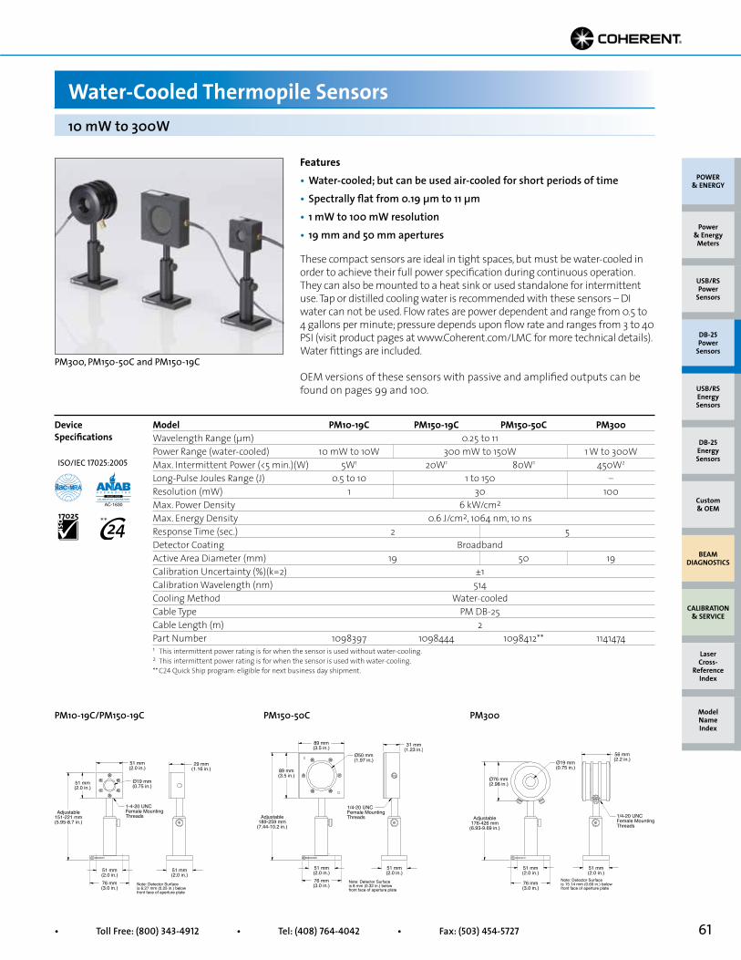
61• Toll Free: (800) 343-4912 • Tel: (408) 764-4042 • Fax: (503) 454-5727
Features• Water-cooled; but can be used air-cooled for short periods of time• Spectrally flat from 0.19 µm to 11 µm• 1 mW to 100 mW resolution• 19 mm and 50 mm apertures
PM300, PM150-50C and PM150-19C
These compact sensors are ideal in tight spaces, but must be water-cooled in order to achieve their full power specification during continuous operation. They can also be mounted to a heat sink or used standalone for intermittent use. Tap or distilled cooling water is recommended with these sensors – DI water can not be used. Flow rates are power dependent and range from 0.5 to 4 gallons per minute; pressure depends upon flow rate and ranges from 3 to 40 PSI (visit product pages at www.Coherent.com/LMC for more technical details). Water fittings are included.
OEM versions of these sensors with passive and amplified outputs can be found on pages 99 and 100.
Model PM10-19C PM150-19C PM150-50C PM300Wavelength Range (µm) 0.25 to 11Power Range (water-cooled) 10 mW to 10W 300 mW to 150W 1 W to 300WMax. Intermittent Power (<5 min.)(W) 5W1 20W1 80W1 450W2
Long-Pulse Joules Range (J) 0.5 to 10 1 to 150 –Resolution (mW) 1 30 100Max. Power Density 6 kW/cm2
Max. Energy Density 0.6 J/cm2, 1064 nm, 10 nsResponse Time (sec.) 2 5Detector Coating BroadbandActive Area Diameter (mm) 19 50 19Calibration Uncertainty (%)(k=2) ±1Calibration Wavelength (nm) 514Cooling Method Water-cooledCable Type PM DB-25Cable Length (m) 2Part Number 1098397 1098444 1098412** 1141474
Device Specifications
1 This intermittent power rating is for when the sensor is used without water-cooling.2 This intermittent power rating is for when the sensor is used with water-cooling.** C24 Quick Ship program: eligible for next business day shipment.
PM300PM150-50CPM10-19C/PM150-19C
10 mW to 300W
Water-Cooled Thermopile Sensors
Adjustable151-221 mm(5.95-8.7 in.)
1-4-20 UNCFemale MountingThreads
51 mm(2.0 in.)
51 mm(2.0 in.)
Ø19 mm(0.75 in.)
51 mm(2.0 in.)
29 mm(1.16 in.)
51 mm(2.0 in.)
76 mm(3.0 in.)
Note: Detector Surfaceis 6.27 mm (0.25 in.) belowfront face of aperture plate
1/4-20 UNCFemale MountingThreads
Ø76 mm(2.98 in.)
Adjustable176-426 mm
(6.93-9.69 in.)
Ø19 mm(0.75 in.)
51 mm(2.0 in.)
51 mm(2.0 in.)
76 mm(3.0 in.)
56 mm(2.2 in.)
Note: Detector Surfaceis 15.14 mm (0.60 in.) belowfront face of aperture plate
1/4-20 UNCFemale MountingThreads
89 mm(3.5 in.)
89 mm(3.5 in.)
Adjustable189-259 mm
(7.44-10.2 in.)
Ø50 mm(1.97 in.)
31 mm(1.23 in.)
51 mm(2.0 in.)
51 mm(2.0 in.)76 mm(3.0 in.)
Note: Detector Surfaceis 8 mm (0.32 in.) belowfront face of aperture plate
POWER & ENERGY
Custom & OEM
BEAM DIAGNOSTICS
CALIBRATION & SERVICE
Power & Energy
Meters
Laser Cross-
Reference Index
Model Name Index
DB-25Energy Sensors
USB/RSEnergy Sensors
DB-25Power
Sensors
USB/RSPower
Sensors
ISO/IEC 17025:2005
**

62 Superior Reliability & Performance • www.Coherent.com • [email protected]
POWER & ENERGY
Custom & OEM
BEAM DIAGNOSTICS
CALIBRATION & SERVICE
Power & Energy
Meters
Laser Cross-
Reference Index
Model Name Index
DB-25Energy Sensors
USB/RSEnergy Sensors
DB-25Power
Sensors
USB/RSPower
Sensors
Features• Fan-cooled• Spectrally flat from 0.19 µm to 11 µm• 100 mW resolution• 19 mm and 50 mm apertures
PM200F-50 and PM300F-50
Fan-cooled sensors are an excellent choice for measuring high power lasers when water-cooling is not possible. A compact power supply provides the 12 VDC required to power the fan.
Model PM200F-19 PM200F-50 PM300F-19 PM300F-50Wavelength Range (µm) 0.25 to 11Power Range (W) 1 to 200 1 to 300Long-Pulse Joules Range (J) 1 to 200 1 to 300Max. Intermittent Power (<5 min.)(W) 300 450Resolution (mW) 100Max. Power Density 6 kW/cm2
Max. Energy Density 0.6 J/cm2, 1064 nm, 10 nsResponse Time (sec.) 2 5 2 5Detector Coating BroadbandActive Area Diameter (mm) 19 50 19 50Calibration Uncertainty (%)(k=2) ±1Calibration Wavelength (nm) 514Cooling Method Fan-cooledCable Type PM DB-25Cable Length (m) 2Part Number 1098480 1098472 1098509 1098417
Device Specifications
PM200F-19/PM200F-50 PM300F-19/PM300F-50
1W to 300W
Fan-Cooled Thermopile Sensors
1/4-20 UNCFemale MountingThreads3 Places
Ø50 mm(1.97 in.)for PM200F-50
Ø19 mm(0.76 in.)for PM200F-19
114 mm(4.49 in.)
102 mm(4.0 in.)
102 mm(4.0 in.)
102 mm(4.0 in.)
51 mm(2.0 in.)102 mm
(4.0 in.)127 mm(5.0 in.)
Note: Detector Surfaceis 11.6 mm (0.45 in.) belowfront face of aperture plate
Adjustable202-272 mm
(7.95-10.71 in.)
1/4-20 UNCFemale MountingThreads3 Places
127 mm(5.0 in.)
127 mm(5.0 in.)
126.6 mm(4.99 in.)
101.6 mm(4.0 in.)
101.7 mm(4.0 in.)
50.7 mm(2.0 in.)
127 mm(5.0 in.)
Ø19 mm(0.75 in.)for PM300F-19
Ø50.8 mm(2.0 in.)for PM300F-50
Note: Detector Surfaceis 10 mm (0.39 in.) belowfront face of aperture plate
Adjustable241-296 mm
(9.49-11.64 in.)
ISO/IEC 17025:2005

63• Toll Free: (800) 343-4912 • Tel: (408) 764-4042 • Fax: (503) 454-5727
Features• Water-cooled• Spectrally flat from 0.19 µm to 11 µm• 1W resolution• 50 mm apertures
Model PM1K
These water-cooled sensors are used to measure lasers over 300W average power output. They are excellent choices for measuring CO2 and Nd:YAG lasers. Larger-area versions are available on the next page.
Tap or distilled cooling water is recommended with these sensors – DI water can not be used. Flow rates are power dependent and range from 0.5 to 4 gallons per minute; pressure depends upon flow rate and ranges from 3 to 40 PSI (visit product pages at www.Coherent.com/LMC for more technical details). Water fittings are included.
Model PM1K PM3K PM5KWavelength Range (µm) 0.25 to 11Power Range (W) 100 to 1000 100 to 3000 100 to 5000Max. Intermittent Power (<5 min.)(W)1 3000 5000 10000Resolution (W) 1Max. Power Density2 1 to 2.5 kW/cm2
Max. Energy Density 0.6 J/cm2, 1064 nm, 10 nsResponse Time (sec.) 30Detector Coating BroadbandActive Area Diameter (mm) 50Calibration Uncertainty (%)(k=2) ±3Calibration Wavelength (nm) 1064Cooling Method Water-cooledCable Type PM DB-25Cable Length (m) 2Part Number 1098392** 1098462** 1098454
Device Specifications
1 Intermittent power levels may be sustainable for longer than 5 minutes when used with lasers with large diameter, non-Gaussian beam profiles. Monitor closely for coating damage if used longer than five minutes at higher powers.2 The damage resistance of the coating is dependent upon the beam size and profile, the average power level, and the water flow rate. Contact Coherent or your local representative for details related to your application.** C24 Quick Ship program: eligible for next business day shipment.
PM1K/PM3K/PM5K
100W to 5 kW
Water-Cooled Thermopile Sensors
3/8-16 UNCFemale MountingThreads
Ø120 mm(4.73 in.) 60 mm
(2.35 in.)
Ø50 mm(1.96 in.)
Ø202 mm(7.95 in.)
Note: Detector Surfaceis 14.3 mm (0.56 in.) belowfront face of aperture plate
POWER & ENERGY
Custom & OEM
BEAM DIAGNOSTICS
CALIBRATION & SERVICE
Power & Energy
Meters
Laser Cross-
Reference Index
Model Name Index
DB-25Energy Sensors
USB/RSEnergy Sensors
DB-25Power
Sensors
USB/RSPower
Sensors
ISO/IEC 17025:2005
**
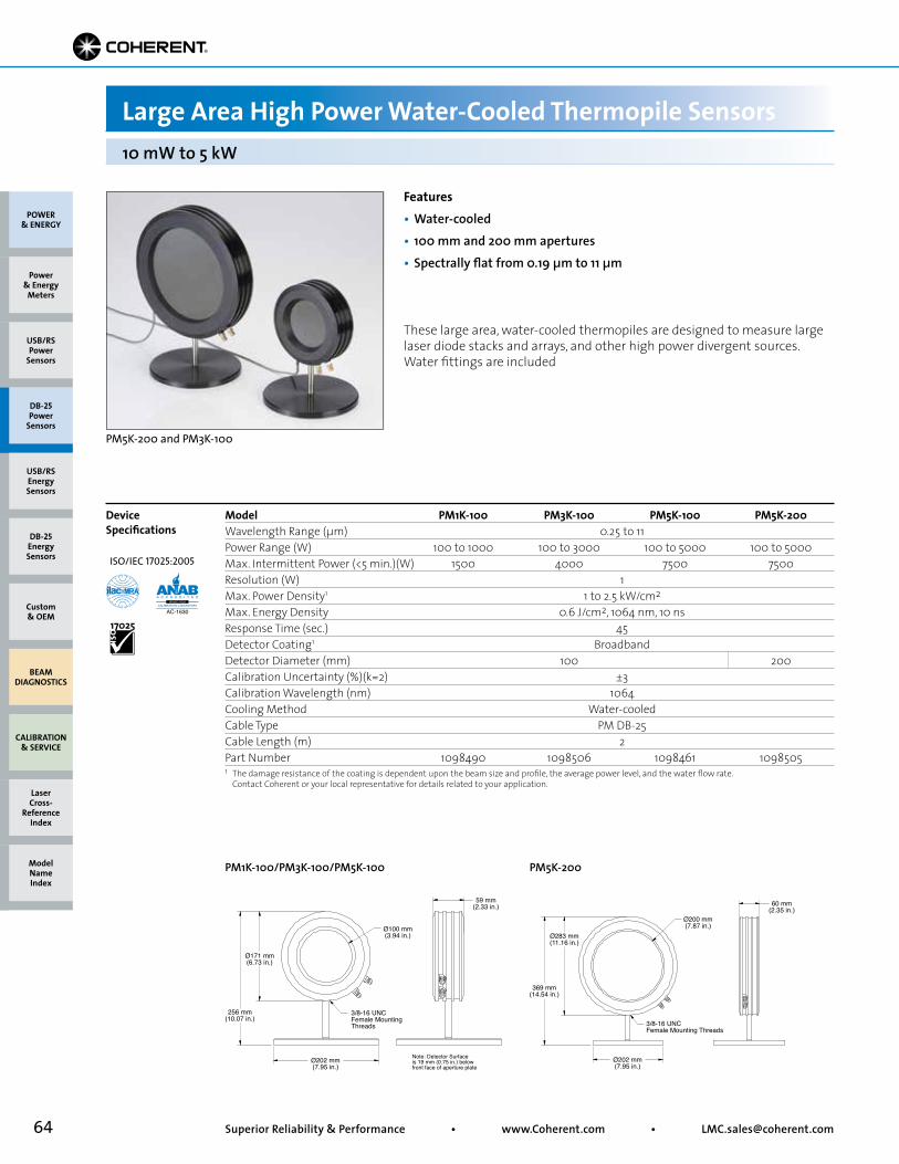
64 Superior Reliability & Performance • www.Coherent.com • [email protected]
POWER & ENERGY
Custom & OEM
BEAM DIAGNOSTICS
CALIBRATION & SERVICE
Power & Energy
Meters
Laser Cross-
Reference Index
Model Name Index
DB-25Energy Sensors
USB/RSEnergy Sensors
DB-25Power
Sensors
USB/RSPower
Sensors
Features• Water-cooled• 100 mm and 200 mm apertures• Spectrally flat from 0.19 µm to 11 µm
PM5K-200 and PM3K-100
These large area, water-cooled thermopiles are designed to measure large laser diode stacks and arrays, and other high power divergent sources. Water fittings are included
Model PM1K-100 PM3K-100 PM5K-100 PM5K-200Wavelength Range (µm) 0.25 to 11Power Range (W) 100 to 1000 100 to 3000 100 to 5000 100 to 5000Max. Intermittent Power (<5 min.)(W) 1500 4000 7500 7500Resolution (W) 1Max. Power Density1 1 to 2.5 kW/cm2
Max. Energy Density 0.6 J/cm2, 1064 nm, 10 nsResponse Time (sec.) 45Detector Coating1 BroadbandDetector Diameter (mm) 100 200Calibration Uncertainty (%)(k=2) ±3Calibration Wavelength (nm) 1064Cooling Method Water-cooledCable Type PM DB-25Cable Length (m) 2Part Number 1098490 1098506 1098461 1098505
Device Specifications
1 The damage resistance of the coating is dependent upon the beam size and profile, the average power level, and the water flow rate. Contact Coherent or your local representative for details related to your application.
PM1K-100/PM3K-100/PM5K-100 PM5K-200
10 mW to 5 kW
Large Area High Power Water-Cooled Thermopile Sensors
3/8-16 UNCFemale MountingThreads
256 mm(10.07 in.)
59 mm(2.33 in.)
Ø171 mm(6.73 in.)
Ø100 mm(3.94 in.)
Ø202 mm(7.95 in.)
Note: Detector Surfaceis 19 mm (0.75 in.) belowfront face of aperture plate
3/8-16 UNCFemale Mounting Threads
369 mm(14.54 in.)
60 mm(2.35 in.)
Ø283 mm(11.16 in.)
Ø200 mm(7.87 in.)
Ø202 mm(7.95 in.)
ISO/IEC 17025:2005
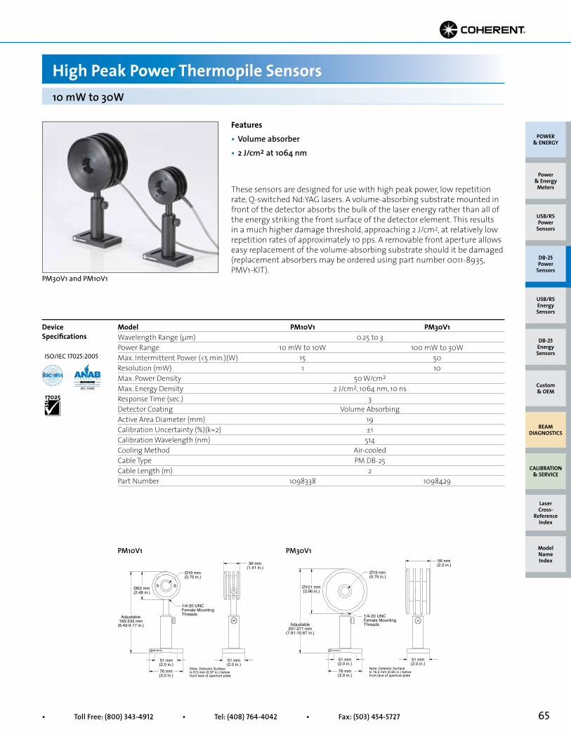
65• Toll Free: (800) 343-4912 • Tel: (408) 764-4042 • Fax: (503) 454-5727
Features• Volume absorber• 2 J/cm2 at 1064 nm
PM30V1 and PM10V1
These sensors are designed for use with high peak power, low repetition rate, Q-switched Nd:YAG lasers. A volume-absorbing substrate mounted in front of the detector absorbs the bulk of the laser energy rather than all of the energy striking the front surface of the detector element. This results in a much higher damage threshold, approaching 2 J/cm2, at relatively low repetition rates of approximately 10 pps. A removable front aperture allows easy replacement of the volume-absorbing substrate should it be damaged (replacement absorbers may be ordered using part number 0011-8935, PMV1-KIT).
Model PM10V1 PM30V1Wavelength Range (µm) 0.25 to 3 Power Range 10 mW to 10W 100 mW to 30WMax. Intermittent Power (<5 min.)(W) 15 50Resolution (mW) 1 10Max. Power Density 50 W/cm2
Max. Energy Density 2 J/cm2, 1064 nm, 10 nsResponse Time (sec.) 3Detector Coating Volume AbsorbingActive Area Diameter (mm) 19Calibration Uncertainty (%)(k=2) ±1Calibration Wavelength (nm) 514 Cooling Method Air-cooledCable Type PM DB-25Cable Length (m) 2Part Number 1098338 1098429
Device Specifications
PM10V1 PM30V1
10 mW to 30W
High Peak Power Thermopile Sensors
Adjustable163-233 mm
(6.42-9.17 in.)
Ø19 mm(0.75 in.)
Ø63 mm(2.48 in.)
36 mm(1.41 in.)
51 mm(2.0 in.)
51 mm(2.0 in.)
76 mm(3.0 in.)
1/4-20 UNCFemale MountingThreads
Note: Detector Surfaceis 9.5 mm (0.37 in.) belowfront face of aperture plate
1/4-20 UNCFemale MountingThreadsAdjustable
201-271 mm(7.91-10.67 in.)
Ø19 mm(0.75 in.)
56 mm(2.2 in.)
Ø101 mm(3.96 in.)
51 mm(2.0 in.)
51 mm(2.0 in.)
76 mm(3.0 in.)
Note: Detector Surfaceis 16.5 mm (0.65 in.) belowfront face of aperture plate
POWER & ENERGY
Custom & OEM
BEAM DIAGNOSTICS
CALIBRATION & SERVICE
Power & Energy
Meters
Laser Cross-
Reference Index
Model Name Index
DB-25Energy Sensors
USB/RSEnergy Sensors
DB-25Power
Sensors
USB/RSPower
Sensors
ISO/IEC 17025:2005

66 Superior Reliability & Performance • www.Coherent.com • [email protected]
POWER & ENERGY
Custom & OEM
BEAM DIAGNOSTICS
CALIBRATION & SERVICE
Power & Energy
Meters
Laser Cross-
Reference Index
Model Name Index
DB-25Energy Sensors
USB/RSEnergy Sensors
DB-25Power
Sensors
USB/RSPower
Sensors
Features• UV coating is optimized for DUV• Spectral range: 0.15 µm to 1 µm• 1 mW to 10 mW resolution• 19 mm apertures
PM2X, PM10X and PM30X
The following sensors are similar to models shown on previous pages, except they incorporate a UV coating that is optimized for use at ultraviolet wavelengths. Spectral compensation allows the sensors to be used from 157 nm to 1064 nm.
Model PM2X PM10X PM30XWavelength Range (µm) 0.15 to 1Power Range 10 mW to 2W 10 mW to 10W 100 mW to 30WLong-Pulse Joules Range (J) 0.5 to 2 0.5 to 10 0.5 to 50Max. Intermittent Power (<5 min.)(W) 5 30 50Resolution (mW) 1 1 10Max. Power Density 6 kW/cm2
Max. Energy Density 0.6 J/cm2, 1064 nm, 10 nsResponse Time (sec.) 2Detector Coating UVActive Area Diameter (mm) 19Calibration Uncertainty (%)(k=2) ±1Calibration Wavelength (nm) 514Cooling Method Air-cooledCable Type PM DB-25Cable Length (m) 2Part Number 1098457 1098423 1098498**
Device Specifications
PM2X PM10x PM30x
10 mW to 30W
Thermopile Sensors with UV Coating
8-32 UNCFemale MountingThreads
51 mm(2.0 in.) Ø19 mm
(0.75 in.)10 mm(0.4 in.)
46 mm(1.8 in.)
51 mm(2.0 in.)
51 mm(2.0 in.)
Adjustable151-221 mm(5.95-8.7 in.)
76 mm(3.0 in.)
Note: Detector Surfaceis 5.5 mm (0.22 in.) belowfront face of aperture plate
1/4-20 UNCFemale MountingThreads
51 mm(2.0 in.)
51 mm(2.0 in.)76 mm(3.0 in.)
Ø19 mm(0.75 in.)
56 mm(2.2 in.)
Ø101 mm(3.96 in.)
Note: Detector Surfaceis 16.5 mm (0.65 in.) belowfront face of aperture plate
Adjustable201-271 mm
(7.91-10.67 in.)
1/4-20 UNCFemale MountingThreads
Adjustable163-233 mm
(6.42-9.17 in.)
Ø19 mm(0.75 in.)
36 mm(1.41 in.)
Ø63 mm(2.48 in.)
51 mm(2.0 in.)
51 mm(2.0 in.)
76 mm(3.0 in.)
Note: Detector Surfaceis 10.9 mm (0.43 in.) belowfront face of aperture plate
** C24 Quick Ship program: eligible for next business day shipment.
ISO/IEC 17025:2005
**

67• Toll Free: (800) 343-4912 • Tel: (408) 764-4042 • Fax: (503) 454-5727
Features• UV coating is optimized for DUV• Spectral Range: 0.15 µm to 1 µm• 30 mW resolution• 50 mm apertures
PM150X and PM150-50XC
Model PM150X PM150-50XCWavelength Range (µm) 0.15 to 1Power Range 300 mW to 150WLong-Pulse Joules Range (J) 1 to 150Max. Intermittent Power (<5 min.)(W) 300 80 (air-cooled)Resolution (mW) 30Max. Power Density 6 kW/cm2
Max. Energy Density 0.6 J/cm2, 1064 nm, 10 nsResponse Time (sec.) 5Detector Coating UVActive Area Diameter (mm) 50Calibration Uncertainty (%)(k=2) ±1Calibration Wavelength (nm) 514Cooling Method Air-cooled Water-cooledCable Type PM DB-25Cable Length (m) 2Part Number1 1098455 1098443
Device Specifications
300 mW to 150W
Thermopile Sensors with UV Coating
1 Water fittings are included with PM150-50XC.
3/8-16 UNCFemale MountingThreads
Ø50 mm(1.97 in.)
Ø151 mm(5.95 in.)
Note: Detector Surfaceis 32.2 mm (1.27 in.) belowfront face of aperture plate
1/4-20 UNCFemale MountingThreadsAdjustable
189-259 mm(7.44-10.2 in.)
Ø50 mm(1.97 in.)
89 mm(3.5 in.)
89 mm(3.5 in.)
31 mm(1.23 in.)
51 mm(2.0 in.)
51 mm(2.0 in.)
76 mm(3.0 in.)
Note: Detector Surfaceis 8 mm (0.32 in.) belowfront face of aperture plate
PM150X PM150-50XC
POWER & ENERGY
Custom & OEM
BEAM DIAGNOSTICS
CALIBRATION & SERVICE
Power & Energy
Meters
Laser Cross-
Reference Index
Model Name Index
DB-25Energy Sensors
USB/RSEnergy Sensors
DB-25Power
Sensors
USB/RSPower
Sensors
ISO/IEC 17025:2005
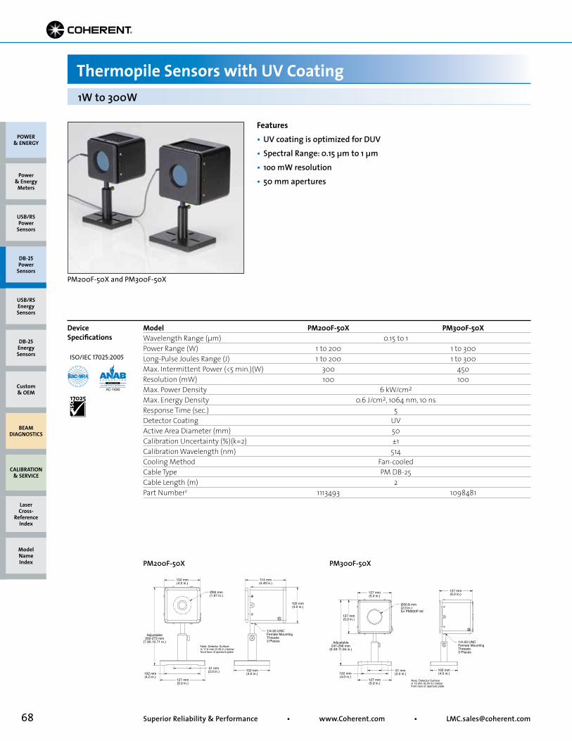
68 Superior Reliability & Performance • www.Coherent.com • [email protected]
Features• UV coating is optimized for DUV• Spectral Range: 0.15 µm to 1 µm• 1oo mW resolution• 50 mm apertures
PM200F-50X and PM300F-50X
Device Specifications
1W to 300W
Thermopile Sensors with UV Coating
Model PM200F-50X PM300F-50XWavelength Range (µm) 0.15 to 1 Power Range (W) 1 to 200 1 to 300Long-Pulse Joules Range (J) 1 to 200 1 to 300Max. Intermittent Power (<5 min.)(W) 300 450Resolution (mW) 100 100Max. Power Density 6 kW/cm2
Max. Energy Density 0.6 J/cm2, 1064 nm, 10 ns Response Time (sec.) 5Detector Coating UVActive Area Diameter (mm) 50Calibration Uncertainty (%)(k=2) ±1Calibration Wavelength (nm) 514Cooling Method Fan-cooledCable Type PM DB-25Cable Length (m) 2Part Number2 1113493 1098481
PM200F-50X
PM300F-50X
1/4-20 UNCFemale MountingThreads3 Places
102 mm(4.0 in.)
Ø50 mm(1.97 in.)
114 mm(4.49 in.)
102 mm(4.0 in.)
102 mm(4.0 in.)
51 mm(2.0 in.)102 mm
(4.0 in.)127 mm(5.0 in.)
Note: Detector Surfaceis 11.6 mm (0.45 in.) belowfront face of aperture plate
Adjustable202-272 mm
(7.95-10.71 in.) 1/4-20 UNCFemale MountingThreads3 Places
127 mm(5.0 in.)
102 mm(4.0 in.)
127 mm(5.0 in.)
51 mm(2.0 in.)
102 mm(4.0 in.)
127 mm(5.0 in.)
Ø50.8 mm(2.0 in.)for PM300F-50
127 mm(5.0 in.)
Note: Detector Surfaceis 10 mm (0.39 in.) belowfront face of aperture plate
Adjustable241-296 mm
(9.49-11.64 in.)
POWER & ENERGY
Custom & OEM
BEAM DIAGNOSTICS
CALIBRATION & SERVICE
Power & Energy
Meters
Laser Cross-
Reference Index
Model Name Index
DB-25Energy Sensors
USB/RSEnergy Sensors
DB-25Power
Sensors
USB/RSPower
Sensors
ISO/IEC 17025:2005
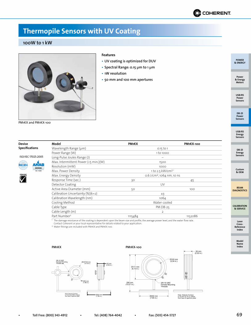
69• Toll Free: (800) 343-4912 • Tel: (408) 764-4042 • Fax: (503) 454-5727
Features• UV coating is optimized for DUV• Spectral Range: 0.15 µm to 1 µm• 1W resolution• 50 mm and 100 mm apertures
PM1KX and PM1KX-100
100W to 1 kW
Thermopile Sensors with UV Coating
POWER & ENERGY
Custom & OEM
BEAM DIAGNOSTICS
CALIBRATION & SERVICE
Power & Energy
Meters
Laser Cross-
Reference Index
Model Name Index
DB-25Energy Sensors
USB/RSEnergy Sensors
DB-25Power
Sensors
USB/RSPower
Sensors
Model PM1KX PM1KX-100Wavelength Range (µm) 0.15 to 1 Power Range (W) 1 to 1000Long-Pulse Joules Range (J) –Max. Intermittent Power (<5 min.)(W) 1500Resolution (mW) 1000Max. Power Density 1 to 2.5 kW/cm2 1
Max. Energy Density 0.6 J/cm2, 1064 nm, 10 ns Response Time (sec.) 30 45Detector Coating UVActive Area Diameter (mm) 50 100Calibration Uncertainty (%)(k=2) ±3Calibration Wavelength (nm) 1064Cooling Method Water-cooledCable Type PM DB-25Cable Length (m) 2Part Number2 1115484 1152086
Device Specifications
1 The damage resistance of the coating is dependent upon the beam size and profile, the average power level, and the water flow rate. Contact Coherent or your local representative for details related to your application.2 Water fittings are included with PM1KX and PM1KX-100.
PM1KX
3/8-16 UNCFemale MountingThreads
Ø120 mm(4.73 in.)
Ø50 mm(1.96 in.)
Ø202 mm(7.95 in.)
60 mm(2.35 in.)
Note: Detector Surfaceis 14.3 mm (0.56 in.) belowfront face of aperture plate
PM1KX-100
3/8-16 UNCFemale MountingThreads
256 mm(10.07 in.)
59 mm(2.33 in.)
Ø171 mm(6.73 in.)
Ø100 mm(3.94 in.)
Ø202 mm(7.95 in.)
Note: Detector Surfaceis 19 mm (0.75 in.) belowfront face of aperture plate
ISO/IEC 17025:2005

70 Superior Reliability & Performance • www.Coherent.com • [email protected]
The Thermal SmartSensor Adapter converts LM-model position-sensing thermopiles and LM-2 optical sensors for use with FieldMaxII, FieldMate and EPM2000 meters.
Designed for use with multiple sensors, this adapter can read the sensor EEPROM contents and program itself when powered up via the meter connection.
Note: Beam position information is not available when using these meters.
This attenuator is used with OP-2 VIS, LM-2 VIS, OP-2 IR and LM-2 IR sensors to allow operation up to 5W in the visible and 3W in the infrared regions. The attenuator threads into the sensor in place of the light shield to provide from 1100:1 to 950:1 attenuation. Each attenuator is calibrated for 1000:1 ±5% at 635 nm and is supplied with a calibration certificate. The useful spectral range is 400 to 1800 nm. The clear input aperture is 0.312” (7.9 mm) in diameter.
Thermal SmartSensor Adapter
Power Sensor Accessories
Part Number Description1056827** Thermal SmartSensor Adapter
Part Number Description1098318** 1000:1 Attenuator for OP-2 and LM-2 Sensors
1000:1 Attenuator
SMA and FC Adapters
Thermal SmartSensor Adapter
1000:1 Attenuator
400
Wavelength (nm)
Atte
nuat
ion
Rat
ion
800:1
900:1
1000:1
1100:1
600 800 1000 1200 1400 1600 1800
Calibrated @ 1000:1 ±5% @ 635 mmCalibrated @ 1000:1 ±5% @ 635 mm
POWER & ENERGY
Custom & OEM
BEAM DIAGNOSTICS
CALIBRATION & SERVICE
Power & Energy
Meters
Laser Cross-
Reference Index
Model Name Index
DB-25Energy Sensors
USB/RSEnergy Sensors
DB-25Power
Sensors
USB/RSPower
Sensors
Ø8 mm(0.31 in.)
Ø44 mm(1.75 in.)
Ø22 mm(0.88 in.)
Ø3 mm(0.12 in.)
5 mm(0.19 in.)
3/4-32 UN-2A
51 mm(2.02 in.)
**
**
** C24 Quick Ship program: eligible for next business day shipment.
** C24 Quick Ship program: eligible for next business day shipment.
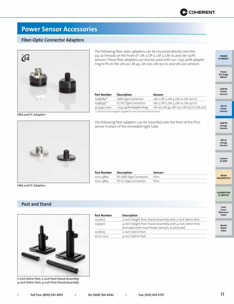
71• Toll Free: (800) 343-4912 • Tel: (408) 764-4042 • Fax: (503) 454-5727
The following fiber-optic adapters can be mounted directly onto the 3/4-32 threads on the front of LM-2, OP-2, LM-3, LM-10, and LM-150FS sensors. These fiber adapters can also be used with our 1.035-40M adapter ring to fit on the LM-20, LM-45, LM-100, LM-150 LS, and LM-200 sensors.
The following fiber adapters can be mounted onto the front of the PS10 sensor in place of the removable light tube.
Fiber-Optic Connector Adapters
Power Sensor Accessories
SMA and FC Adapters
SMA and FC Adapters
Part Number Description Sensors1098589** SMA-Type Connector LM-2, OP-2, LM-3, LM-10, LM-150 FS1098339** FC/PC-Type Connector LM-2, OP-2, LM-3, LM-10, LM-150 FS33-9432-000 1.035-40M Adapter Ring LM-20, LM-45, LM-100, LM-150 LS, LM-200
Part Number Description Sensors0012-3860 PS-SMA-Type Connector PS100012-3863 PS-FC-Type Connector PS10
POWER & ENERGY
Custom & OEM
BEAM DIAGNOSTICS
CALIBRATION & SERVICE
Power & Energy
Meters
Laser Cross-
Reference Index
Model Name Index
DB-25Energy Sensors
USB/RSEnergy Sensors
DB-25Power
Sensors
USB/RSPower
Sensors
Part Number Description1257607 2-inch Height Post/Stand Assembly with 2-inch Delrin Post1097917 4-inch Height Post/Stand Assembly with 4-inch Delrin Post (included with most Power Sensors, as pictured)1257605 2-inch Delrin Post0010-1220 4-inch Delrin Post
Post and Stand
2-inch Delrin Post, 2-inch Post/Stand Assembly, 4-inch Delrin Post, 4-inch Post/Stand Assembly
**
** C24 Quick Ship program: eligible for next business day shipment.
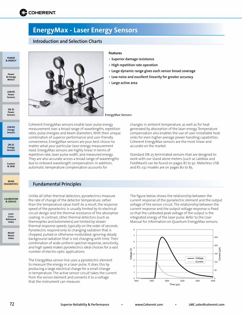
72 Superior Reliability & Performance • www.Coherent.com • [email protected]
Coherent EnergyMax sensors enable laser pulse energy measurement over a broad range of wavelengths, repetition rates, pulse energies and beam diameters. With their unique combination of superior performance and user-friendly convenience, EnergyMax sensors are your best choice no matter what your particular laser energy measurement need. EnergyMax sensors are highly linear in terms of repetition rate, laser pulse width, and measured energy. They are also accurate across a broad range of wavelengths due to onboard wavelength compensation. In addition, automatic temperature compensation accounts for
changes in ambient temperature, as well as for heat generated by absorption of the laser energy. Temperature compensation also enables the use of user-installable heat sinks for even higher average power handling capabilities. Coherent EnergyMax sensors are the most linear and accurate on the market.
Standard DB-25 terminated sensors that are designed to work with our stand alone meters (such as LabMax and FieldMaxII) can be found on pages 87 to 92. Meterless USB and RS-232 models are on pages 80 to 85.
Introduction and Selection Charts
EnergyMax - Laser Energy Sensors
Features• Superior damage resistance• High repetition rate operation• Large dynamic range gives each sensor broad coverage• Low noise and excellent linearity for greater accuracy• Large active area
Unlike all other thermal detectors, pyroelectrics measure the rate of change of the detector temperature, rather than the temperature value itself. As a result, the response speed of the pyroelectric is usually limited by its electrical circuit design and the thermal resistance of the absorptive coating. In contrast, other thermal detectors (such as thermopiles and bolometers) are limited by slower thermal response speeds, typically on the order of seconds. Pyroelectric respond only to changing radiation that is chopped, pulsed or otherwise modulated; ignoring steady background radiation that is not changing with time. Their combination of wide uniform spectral response, sensitivity, and high speed makes pyroelectrics ideal choices for a vast number of electro-optic applications.
The EnergyMax sensor line uses a pyroelectric element to measure the energy in a laser pulse. It does this by producing a large electrical charge for a small change in temperature. The active sensor circuit takes the current from the sensor element and converts it to a voltage that the instrument can measure.
The figure below shows the relationship between the current response of the pyroelectric element and the output voltage of the sensor circuit. The relationship between the current response and the output voltage response is fixed so that the calibrated peak voltage of the output is the integrated energy of the laser pulse. Refer to the User Manual for information on Quantum EnergyMax sensors.
Fundamental Principles
EnergyMax Sensors
POWER & ENERGY
Custom & OEM
BEAM DIAGNOSTICS
CALIBRATION & SERVICE
Power & Energy
Meters
Laser Cross-
Reference Index
Model Name Index
DB-25Energy Sensors
USB/RSEnergy Sensors
DB-25Power
Sensors
USB/RSPower
Sensors
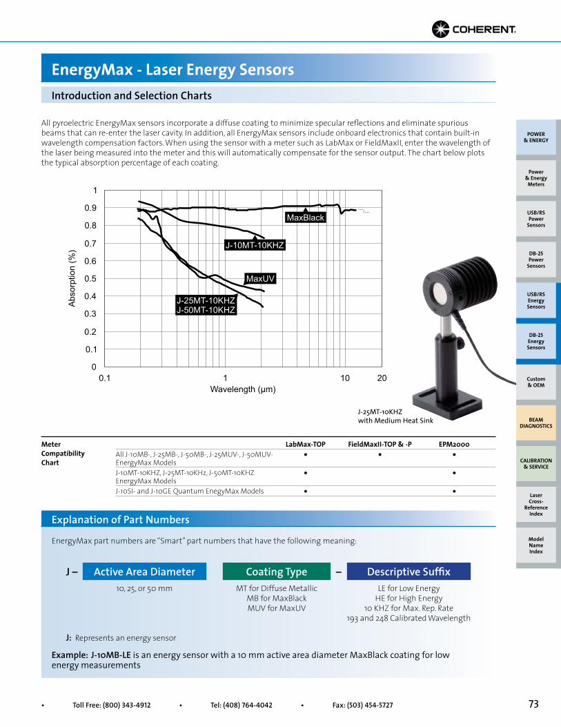
73• Toll Free: (800) 343-4912 • Tel: (408) 764-4042 • Fax: (503) 454-5727
All pyroelectric EnergyMax sensors incorporate a diffuse coating to minimize specular reflections and eliminate spurious beams that can re-enter the laser cavity. In addition, all EnergyMax sensors include onboard electronics that contain built-in wavelength compensation factors. When using the sensor with a meter such as LabMax or FieldMaxII, enter the wavelength of the laser being measured into the meter and this will automatically compensate for the sensor output. The chart below plots the typical absorption percentage of each coating.
Wavelength (µm) 0.1 20 10 1
0.1
0
0.2
0.3
0.4
0.5
0.6
0.7
0.8
0.9
1
MaxBlack
J-10MT-10KHZ
MaxUV
Abs
orpt
ion
(%)
J-25MT-10KHZ J-50MT-10KHZ
Introduction and Selection Charts
EnergyMax - Laser Energy Sensors
LabMax-TOP FieldMaxII-TOP & -P EPM2000All J-10MB-, J-25MB-, J-50MB-, J-25MUV-, J-50MUV- • • •EnergyMax ModelsJ-10MT-10KHZ, J-25MT-10KHz, J-50MT-10KHZ • •EnergyMax ModelsJ-10SI- and J-10GE Quantum EnegyMax Models • •
Meter Compatibility Chart
EnergyMax part numbers are “Smart” part numbers that have the following meaning:
Example: J-10MB-LE is an energy sensor with a 10 mm active area diameter MaxBlack coating for low energy measurements
10, 25, or 50 mm MT for Diffuse MetallicMB for MaxBlackMUV for MaxUV
LE for Low EnergyHE for High Energy
10 KHZ for Max. Rep. Rate193 and 248 Calibrated Wavelength
J: Represents an energy sensor
Explanation of Part Numbers
Active Area Diameter Descriptive SuffixCoating TypeJ – –
J-25MT-10KHZ with Medium Heat Sink
POWER & ENERGY
Custom & OEM
BEAM DIAGNOSTICS
CALIBRATION & SERVICE
Power & Energy
Meters
Laser Cross-
Reference Index
Model Name Index
DB-25Energy Sensors
USB/RSEnergy Sensors
DB-25Power
Sensors
USB/RSPower
Sensors

74 Superior Reliability & Performance • www.Coherent.com • [email protected]
Overall measurement accuracy is a combination of calibration uncertainty (found in the sensor specification tables) and the wavelength compensation accuracy (found in the “Wavelength Compensation Accuracy” table, below).
The combined accuracy is based upon practices outlined in the National Institute of Standards Guidelines for Evaluating and Expressing Uncertainty (NIST Technical Note 1297, 1994 Edition). The combined accuracy of the measurement is calculated by using the law of propagation of uncertainty using the “root-sum-of-square” (square root of the sum of squares), sometimes described as “summing in quadrature” where:
Applying Wavelength Compensation Accuracy
EnergyMax - Laser Energy Sensors
22 + 22 4 + 4
32 + 52 9 + 25
Measurement Accuracy =
where U = ‘Percent Calibration Uncertainty’ and W = ‘Wavelength Accuracy’
Example 1
J-10SI-HE used at 355 nm
U = 3%W = 5%
Measurement Accuracy = = = 5.8%
Example 2
J-10MB-LE used at 532 nm
U = 2%W = 2%
Measurement Accuracy = = = 2.8%
Wavelength Compensation Accuracy (%) Calibration (for wavelengths other than the WavelengthModel calibration wavelength) (nm)All Multipurpose Sensors (MaxBlack Coating) ±2 1064All High Repetition Rate Sensors (Diffuse Metallic Coating) ±3 1064 J-50MB-YAG ±2 1064J-50MB-IR ±3 1064, 2940 J-25MB-IR ±4 1064 J-25MUV-193 ±3 193J-25MUV-248 ±3 248J-50MUV-193 ±4 193J-50MUV-248 ±4 248J-10SI-LE ±5 532J-10SI-HE ±5 532J-10GE ±5 1064
Wavelength Compensation Accuracy
U2 + W2
POWER & ENERGY
Custom & OEM
BEAM DIAGNOSTICS
CALIBRATION & SERVICE
Power & Energy
Meters
Laser Cross-
Reference Index
Model Name Index
DB-25Energy Sensors
USB/RSEnergy Sensors
DB-25Power
Sensors
USB/RSPower
Sensors
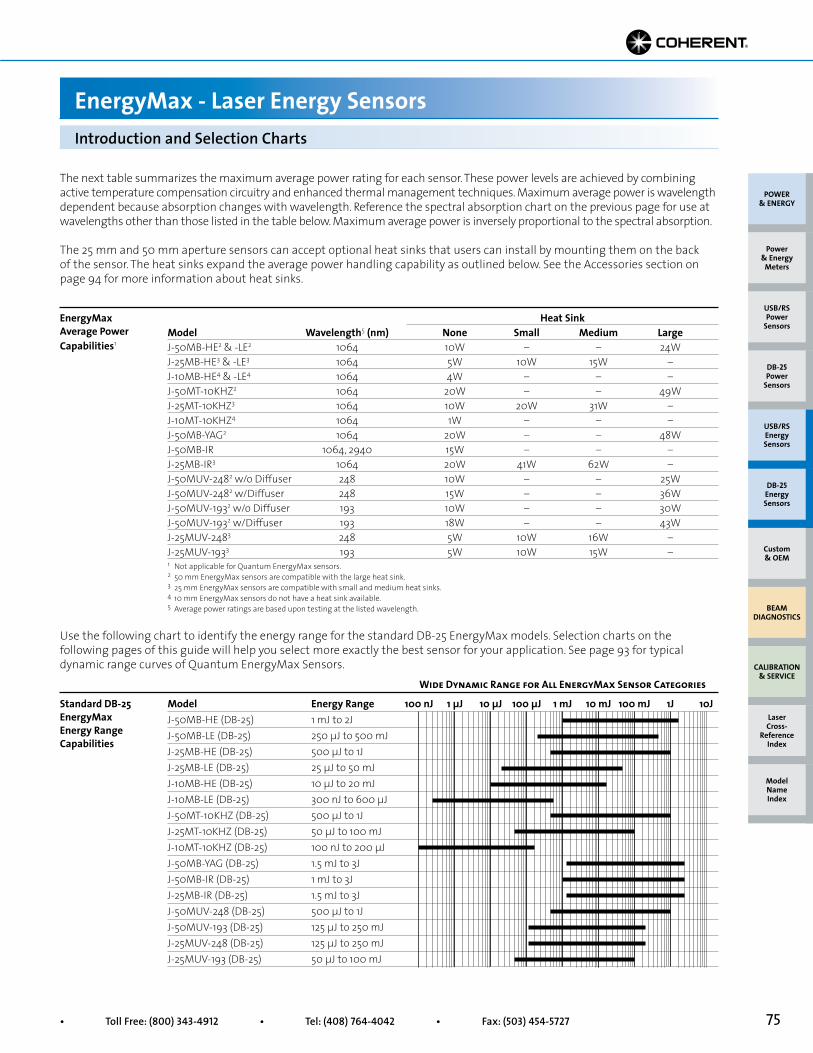
75• Toll Free: (800) 343-4912 • Tel: (408) 764-4042 • Fax: (503) 454-5727
Introduction and Selection Charts
EnergyMax - Laser Energy Sensors
Use the following chart to identify the energy range for the standard DB-25 EnergyMax models. Selection charts on the following pages of this guide will help you select more exactly the best sensor for your application. See page 93 for typical dynamic range curves of Quantum EnergyMax Sensors.
Model Energy Range 100 nJ 1 µJ 10 µJ 100 µJ 1 mJ 10 mJ 100 mJ 1J 10JJ-50MB-HE (DB-25) 1 mJ to 2JJ-50MB-LE (DB-25) 250 µJ to 500 mJJ-25MB-HE (DB-25) 500 µJ to 1JJ-25MB-LE (DB-25) 25 µJ to 50 mJJ-10MB-HE (DB-25) 10 µJ to 20 mJJ-10MB-LE (DB-25) 300 nJ to 600 µJJ-50MT-10KHZ (DB-25) 500 µJ to 1JJ-25MT-10KHZ (DB-25) 50 µJ to 100 mJJ-10MT-10KHZ (DB-25) 100 nJ to 200 µJJ-50MB-YAG (DB-25) 1.5 mJ to 3JJ-50MB-IR (DB-25) 1 mJ to 3JJ-25MB-IR (DB-25) 1.5 mJ to 3JJ-50MUV-248 (DB-25) 500 µJ to 1JJ-50MUV-193 (DB-25) 125 µJ to 250 mJJ-25MUV-248 (DB-25) 125 µJ to 250 mJJ-25MUV-193 (DB-25) 50 µJ to 100 mJ
Standard DB-25 EnergyMax Energy Range Capabilities
Wide Dynamic Range for All EnergyMax Sensor Categories
Heat SinkModel Wavelength5 (nm) None Small Medium LargeJ-50MB-HE2 & -LE2 1064 10W – – 24WJ-25MB-HE3 & -LE3 1064 5W 10W 15W –J-10MB-HE4 & -LE4 1064 4W – – –J-50MT-10KHZ2 1064 20W – – 49WJ-25MT-10KHZ3 1064 10W 20W 31W –J-10MT-10KHZ4 1064 1W – – –J-50MB-YAG2 1064 20W – – 48WJ-50MB-IR 1064, 2940 15W – – –J-25MB-IR3 1064 20W 41W 62W –J-50MUV-2482 w/o Diffuser 248 10W – – 25WJ-50MUV-2482 w/Diffuser 248 15W – – 36WJ-50MUV-1932 w/o Diffuser 193 10W – – 30WJ-50MUV-1932 w/Diffuser 193 18W – – 43WJ-25MUV-2483 248 5W 10W 16W –J-25MUV-1933 193 5W 10W 15W –
EnergyMax Average Power Capabilities1
1 Not applicable for Quantum EnergyMax sensors.2 50 mm EnergyMax sensors are compatible with the large heat sink.3 25 mm EnergyMax sensors are compatible with small and medium heat sinks.4 10 mm EnergyMax sensors do not have a heat sink available.5 Average power ratings are based upon testing at the listed wavelength.
The next table summarizes the maximum average power rating for each sensor. These power levels are achieved by combining active temperature compensation circuitry and enhanced thermal management techniques. Maximum average power is wavelength dependent because absorption changes with wavelength. Reference the spectral absorption chart on the previous page for use at wavelengths other than those listed in the table below. Maximum average power is inversely proportional to the spectral absorption.
The 25 mm and 50 mm aperture sensors can accept optional heat sinks that users can install by mounting them on the back of the sensor. The heat sinks expand the average power handling capability as outlined below. See the Accessories section on page 94 for more information about heat sinks.
POWER & ENERGY
Custom & OEM
BEAM DIAGNOSTICS
CALIBRATION & SERVICE
Power & Energy
Meters
Laser Cross-
Reference Index
Model Name Index
DB-25Energy Sensors
USB/RSEnergy Sensors
DB-25Power
Sensors
USB/RSPower
Sensors
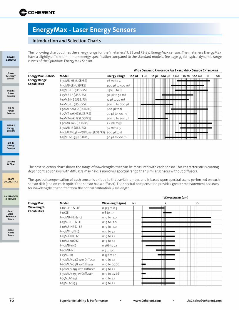
76 Superior Reliability & Performance • www.Coherent.com • [email protected]
Introduction and Selection Charts
EnergyMax - Laser Energy Sensors
The next selection chart shows the range of wavelengths that can be measured with each sensor. This characteristic is coating dependent, so sensors with diffusers may have a narrower spectral range than similar sensors without diffusers.
The spectral compensation of each sensor is unique to that serial number, and is based upon spectral scans performed on each sensor disk (and on each optic if the sensor has a diffuser). The spectral compensation provides greater measurement accuracy for wavelengths that differ from the optical calibration wavelength.
Model Wavelength (µm) 0.1 1 10J-10SI-HE & -LE 0.325 to 0.9J-10GE 0.8 to 1.7J-50MB-HE & -LE 0.19 to 12.0 J-25MB-HE & -LE 0.19 to 12.0J-10MB-HE & -LE 0.19 to 12.0J-50MT-10KHZ 0.19 to 2.1J-25MT-10KHZ 0.19 to 2.1J-10MT-10KHZ 0.19 to 2.1J-50MB-YAG 0.266 to 2.1J-50MB-IR 0.5 to 3.0J-25MB-IR 0.532 to 2.1J-50MUV-248 w/o Diffuser 0.19 to 2.1J-50MUV-248 w/Diffuser 0.19 to 0.266J-50MUV-193 w/o Diffuser 0.19 to 2.1J-50MUV-193 w/Diffuser 0.19 to 0.266J-25MUV-248 0.19 to 2.1J-25MUV-193 0.19 to 2.1
EnergyMax Wavelength Capabilities
Wavelength (µm)
The following chart outlines the energy range for the “meterless” USB and RS-232 EnergyMax sensors. The meterless EnergyMax have a slightly different minimum energy specification compared to the standard models. See page 93 for typical dynamic range curves of the Quantum EnergyMax Sensor.
Model Energy Range 100 nJ 1 µJ 10 µJ 100 µJ 1 mJ 10 mJ 100 mJ 1J 10JJ-50MB-HE (USB/RS) 1.6 mJ to 2JJ-50MB-LE (USB/RS) 400 µJ to 500 mJJ-25MB-HE (USB/RS) 850 µJ to 1JJ-25MB-LE (USB/RS) 50 µJ to 50 mJJ-10MB-HE (USB/RS) 12 µJ to 20 mJJ-10MB-LE (USB/RS) 500 nJ to 600 µJJ-50MT-10KHZ (USB/RS) 400 µJ to 1JJ-25MT-10KHZ (USB/RS) 90 µJ to 100 mJJ-10MT-10KHZ (USB/RS) 300 nJ to 200 µJJ-50MB-YAG (USB/RS) 2.4 mJ to 3JJ-50MB-IR (USB/RS) 3.2 mJ to 3JJ-50MUV-248 w/Diffuser (USB/RS) 800 µJ to 1JJ-25MUV-193 (USB/RS) 90 µJ to 100 mJ
EnergyMax-USB/RS Energy Range Capabilities
Wide Dynamic Range for All EnergyMax Sensor Categories
POWER & ENERGY
Custom & OEM
BEAM DIAGNOSTICS
CALIBRATION & SERVICE
Power & Energy
Meters
Laser Cross-
Reference Index
Model Name Index
DB-25Energy Sensors
USB/RSEnergy Sensors
DB-25Power
Sensors
USB/RSPower
Sensors
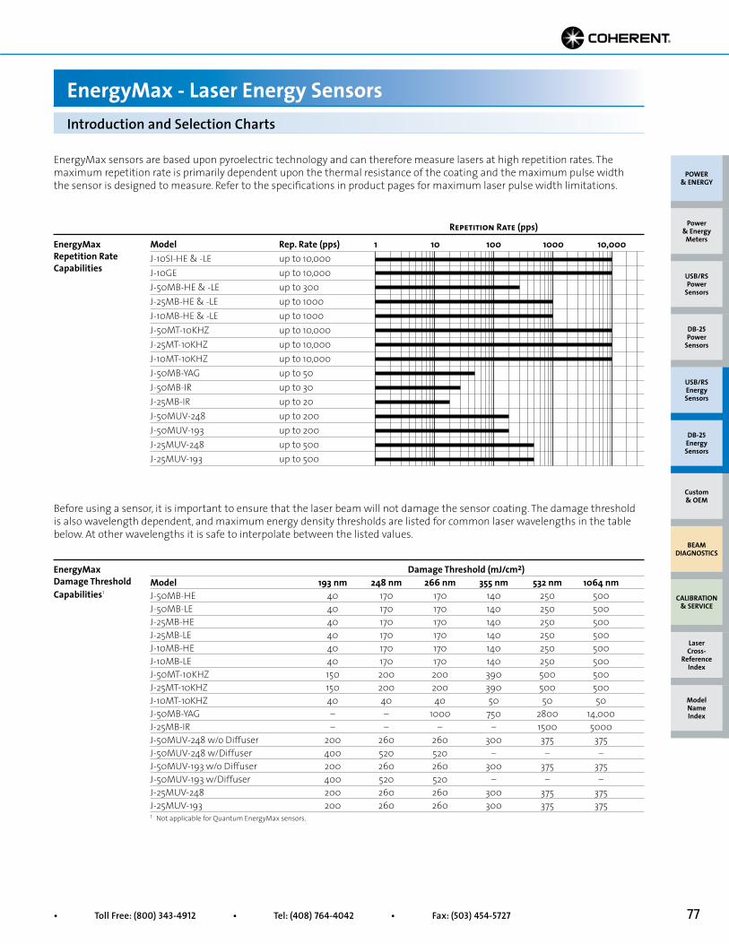
77• Toll Free: (800) 343-4912 • Tel: (408) 764-4042 • Fax: (503) 454-5727
EnergyMax sensors are based upon pyroelectric technology and can therefore measure lasers at high repetition rates. The maximum repetition rate is primarily dependent upon the thermal resistance of the coating and the maximum pulse width the sensor is designed to measure. Refer to the specifications in product pages for maximum laser pulse width limitations.
Model Rep. Rate (pps) 1 10 100 1000 10,000J-10SI-HE & -LE up to 10,000J-10GE up to 10,000J-50MB-HE & -LE up to 300J-25MB-HE & -LE up to 1000J-10MB-HE & -LE up to 1000J-50MT-10KHZ up to 10,000J-25MT-10KHZ up to 10,000J-10MT-10KHZ up to 10,000J-50MB-YAG up to 50J-50MB-IR up to 30J-25MB-IR up to 20J-50MUV-248 up to 200J-50MUV-193 up to 200J-25MUV-248 up to 500J-25MUV-193 up to 500
EnergyMax Repetition Rate Capabilities
Repetition Rate (pps)
Introduction and Selection Charts
EnergyMax - Laser Energy Sensors
Before using a sensor, it is important to ensure that the laser beam will not damage the sensor coating. The damage threshold is also wavelength dependent, and maximum energy density thresholds are listed for common laser wavelengths in the table below. At other wavelengths it is safe to interpolate between the listed values.
Damage Threshold (mJ/cm2)Model 193 nm 248 nm 266 nm 355 nm 532 nm 1064 nmJ-50MB-HE 40 170 170 140 250 500J-50MB-LE 40 170 170 140 250 500J-25MB-HE 40 170 170 140 250 500J-25MB-LE 40 170 170 140 250 500J-10MB-HE 40 170 170 140 250 500J-10MB-LE 40 170 170 140 250 500J-50MT-10KHZ 150 200 200 390 500 500J-25MT-10KHZ 150 200 200 390 500 500J-10MT-10KHZ 40 40 40 50 50 50J-50MB-YAG – – 1000 750 2800 14,000J-25MB-IR – – – – 1500 5000J-50MUV-248 w/o Diffuser 200 260 260 300 375 375J-50MUV-248 w/Diffuser 400 520 520 – – –J-50MUV-193 w/o Diffuser 200 260 260 300 375 375J-50MUV-193 w/Diffuser 400 520 520 – – –J-25MUV-248 200 260 260 300 375 375J-25MUV-193 200 260 260 300 375 375
EnergyMax Damage Threshold Capabilities1
1 Not applicable for Quantum EnergyMax sensors.
POWER & ENERGY
Custom & OEM
BEAM DIAGNOSTICS
CALIBRATION & SERVICE
Power & Energy
Meters
Laser Cross-
Reference Index
Model Name Index
DB-25Energy Sensors
USB/RSEnergy Sensors
DB-25Power
Sensors
USB/RSPower
Sensors
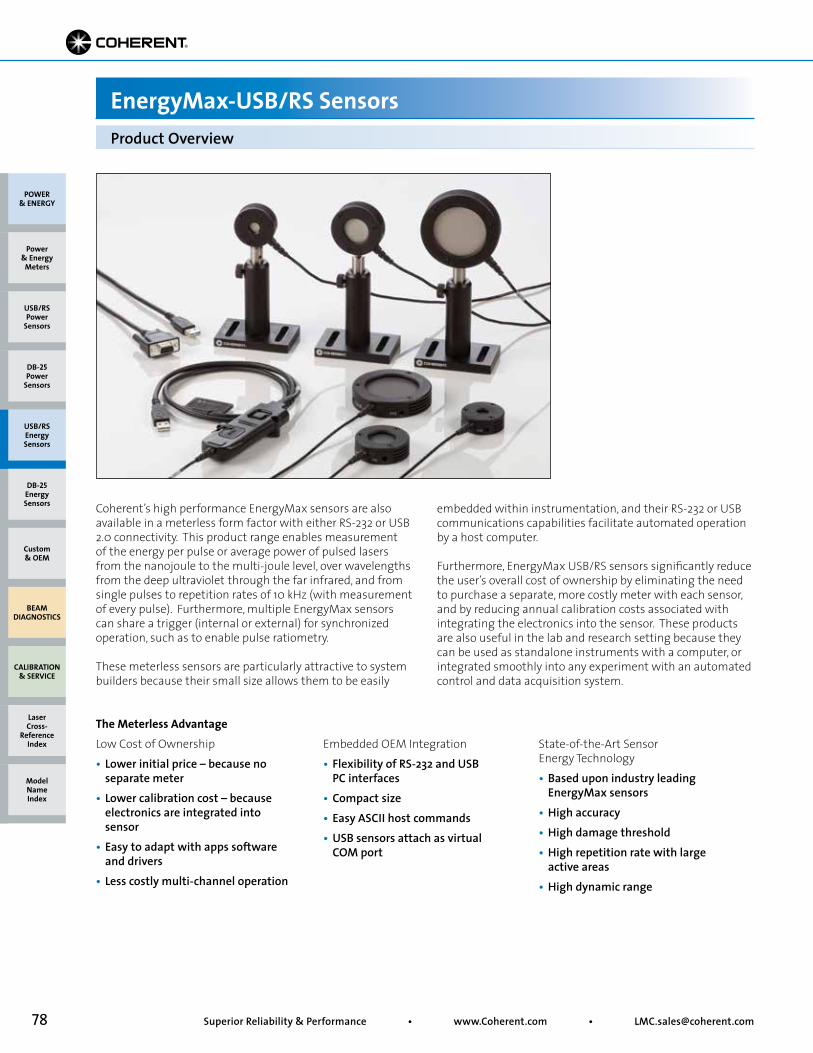
78 Superior Reliability & Performance • www.Coherent.com • [email protected]
Product Overview
EnergyMax-USB/RS Sensors
Coherent’s high performance EnergyMax sensors are also available in a meterless form factor with either RS-232 or USB 2.0 connectivity. This product range enables measurement of the energy per pulse or average power of pulsed lasers from the nanojoule to the multi-joule level, over wavelengths from the deep ultraviolet through the far infrared, and from single pulses to repetition rates of 10 kHz (with measurement of every pulse). Furthermore, multiple EnergyMax sensors can share a trigger (internal or external) for synchronized operation, such as to enable pulse ratiometry.
These meterless sensors are particularly attractive to system builders because their small size allows them to be easily
embedded within instrumentation, and their RS-232 or USB communications capabilities facilitate automated operation by a host computer.
Furthermore, EnergyMax USB/RS sensors significantly reduce the user’s overall cost of ownership by eliminating the need to purchase a separate, more costly meter with each sensor, and by reducing annual calibration costs associated with integrating the electronics into the sensor. These products are also useful in the lab and research setting because they can be used as standalone instruments with a computer, or integrated smoothly into any experiment with an automated control and data acquisition system.
The Meterless AdvantageLow Cost of Ownership• Lower initial price – because no separate meter• Lower calibration cost – because electronics are integrated into sensor• Easy to adapt with apps software and drivers• Less costly multi-channel operation
Embedded OEM Integration• Flexibility of RS-232 and USB PC interfaces• Compact size• Easy ASCII host commands• USB sensors attach as virtual COM port
State-of-the-Art Sensor Energy Technology• Based upon industry leading EnergyMax sensors• High accuracy• High damage threshold• High repetition rate with large active areas• High dynamic range
POWER & ENERGY
Custom & OEM
BEAM DIAGNOSTICS
CALIBRATION & SERVICE
Power & Energy
Meters
Laser Cross-
Reference Index
Model Name Index
DB-25Energy Sensors
USB/RSEnergy Sensors
DB-25Power
Sensors
USB/RSPower
Sensors
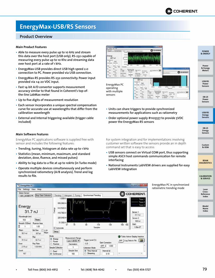
79• Toll Free: (800) 343-4912 • Tel: (408) 764-4042 • Fax: (503) 454-5727
Main Product Features• Able to measure every pulse up to 10 kHz and stream this data over the host port (USB only). RS-232 capable of measuring every pulse up to 10 Khz and streaming data over host port at a rate of 1 kHz.• EnergyMax-USB provides direct USB high speed 2.0 connection to PC. Power provided via USB connection. • EnergyMax-RS provides RS-232 connectivity. Power input provided via +4-20 VDC input. • Fast 14-bit A/D converter supports measurement accuracy similar to that found in Coherent’s top-of- the-line LabMax meter • Up to five digits of measurement resolution • Each sensor incorporates a unique spectral compensation curve for accurate use at wavelengths that differ from the calibration wavelength• External and Internal triggering available (trigger cable included)
Main Software FeaturesEnergyMax PC applications software is supplied free with sensor and includes the following features:• Trending, tuning, histogram at data rate up to 1 kHz• Statistics (mean, minimum, maximum, and standard deviation, dose, fluence, and missed pulses)• Ability to log data to a file at up to 10kHz (in Turbo mode)• Operate multiple devices simultaneously and perform synchronized ratiometery (A/B analysis). Trend and log results to file.
• Units can share triggers to provide synchronized measurements for applications such as ratiometry• Order optional power supply #1105557 to provide 5VDC power the EnergyMax-RS sensors
For system integration and for implementations involving customer written software the sensors provide an in depth command set that is easy to access: • USB sensors connect on Virtual COM port, thus supporting simple ASCII host commands communication for remote interfacing • National Instruments LabVIEW drivers are supplied for easy LabVIEW integration
Product Overview
EnergyMax-USB/RS Sensors
EnergyMax PC in synchronized ratiometric trending mode
EnergyMax PC operating with multiple sensors
POWER & ENERGY
Custom & OEM
BEAM DIAGNOSTICS
CALIBRATION & SERVICE
Power & Energy
Meters
Laser Cross-
Reference Index
Model Name Index
DB-25Energy Sensors
USB/RSEnergy Sensors
DB-25Power
Sensors
USB/RSPower
Sensors
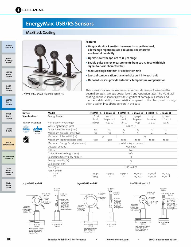
80 Superior Reliability & Performance • www.Coherent.com • [email protected]
Model J-50MB-HE J-50MB-LE J-25MB-HE J-25MB-LE J-10MB-HE J-10MB-LEEnergy Range 1.6 mJ 400 µJ 850 µJ 50 µJ 12 µJ 500 nJ to 2J to 500 mJ to 1J to 50 mJ to 20 mJ to 600 µJNoise Equivalent Energy <160 µJ <40 µJ <85 µJ <5 µJ <1.2 µJ <50 nJWavelength Range (µm) 0.19 to 12Active Area Diameter (mm) 50 50 25 25 10 10Maximum Average Power (W) 10 10 5 5 4 4Maximum Pulse Width (µs) 57 17Maximum Repetition Rate (pps) 300 300 1000 1000 1000 1000Maximum Energy Density (mJ/cm2) 500 (at 1064 nm, 10 ns)Detector Coating MaxBlackDiffuser NoCalibration Wavelength (nm) 1064Calibration Uncertainty (%)(k=2) ±2Energy Linearity (%) ±3Cable Length (m) 3Cable Type USB and RSPart Number USB 1191444 1191443 1191442 1191441 1191436 1191435 RS 1191432 – – 1191431 1191429 1191428
These sensors allow measurements over a wide range of wavelengths, beam diameters, average power levels, and repetition rates. The MaxBlack coating on these sensors provides significant damage resistance and mechanical durability characteristics compared to the black paint coatings often used on broadband sensors in the past.
Adjustable200.15 mm
(7.88 in.) Max.117.60 mm
(4.63 in.) Min.
Aperture Plate
Ø 50.80 mm(2.0 in.)
Ø 25.25 mm (0.99 in.)
16.54 mm(0.65 in.)
76.20 mm(3.0 in.)
50.80 mm(2.0 in.)
2X 5.84 mm(0.23 in.)
M6-6H THD X 5.08 mm (0.20 in.) and No. 1/4-20 UNC-2B THDX 5.08 mm (0.20 in.) for Mounting Sensor
Note: Detector Surface is 3.81 mm (0.15 in.) Below Front Face of Aperture Plate
J-25MB-HE and -LE
Adjustable225.55 mm
(8.88 in.) Max.143.00 mm
(5.63 in.) Min.
Ø 76.20 mm(3.0 in.)
Ø 50.20 mm (1.98 in.)
16.38 mm(0.65 in.)
76.2 mm(3.0 in.)
50.8 mm(2.0 in.)
2X 5.08 mm(0.20 in.)
M6-6H THD X 6.10 mm (0.24 in.) and No. 1/4-20 UNC-2B THDX 6.10 mm (0.24 in.) for Mounting Sensor
Note: Detector Surface is 3.81 mm (0.15 in.) Below Front Face of Aperture Plate
J-50MB-HE and -LE
Adjustable189.99 mm
(7.48 in.) Max.107.44 mm
(4.23 in.) Min.
Aperture Plate
Ø 40.64 mm(1.6 in.)
Ø 10.5 mm (0.41 in.)
15.75 mm(0.62 in.)
50.80 mm(2.0 in.)
76.20 mm(3.0 in.)
2X 5.08 mm(0.2 in.)
M4 X 17.78 mm (0.7 in.) THD X 4.57 mm (0.18 in.) and No. 8-32 UNC-2B THD X 6.35 mm (0.25 in.) for Mounting Sensor
Note: Detector Surface is 3.81 mm (0.15 in.) Below Front Face of Aperture Plate
J-10MB-HE and -LE
MaxBlack Coating
EnergyMax-USB/RS Sensors
Device Specifications
Features• Unique MaxBlack coating increases damage threshold, allows high repetition rate operation, and improves mechanical durability• Operate over the 190 nm to 12 µm range• Enable pulse energy measurements from 500 nJ to 2J with high signal-to-noise characteristics• Measure single shot to 1 kHz repetition rate• Spectral compensation characteristics built into each unit• Onboard sensors provide automatic temperature compensation
J-50MB-HE, J-25MB-HE and J-10MB-HE
POWER & ENERGY
Custom & OEM
BEAM DIAGNOSTICS
CALIBRATION & SERVICE
Power & Energy
Meters
Laser Cross-
Reference Index
Model Name Index
DB-25Energy Sensors
USB/RSEnergy Sensors
DB-25Power
Sensors
USB/RSPower
Sensors
ISO/IEC 17025:2005
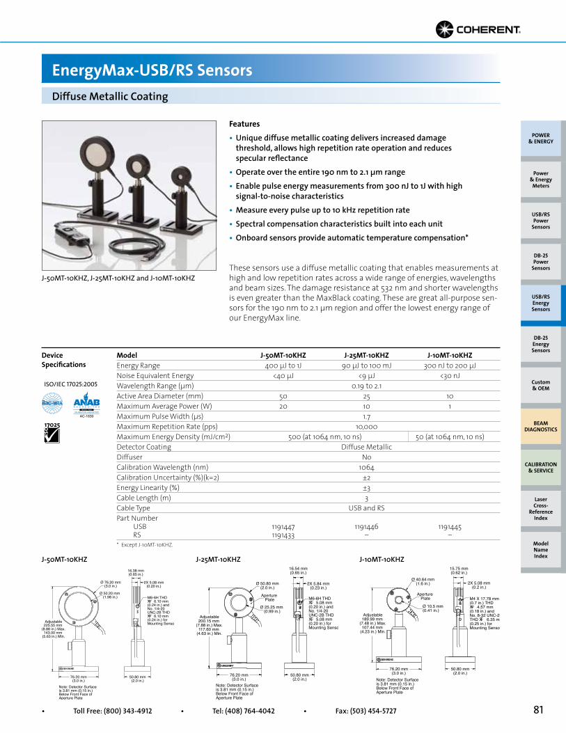
81• Toll Free: (800) 343-4912 • Tel: (408) 764-4042 • Fax: (503) 454-5727
Model J-50MT-10KHZ J-25MT-10KHZ J-10MT-10KHZEnergy Range 400 µJ to 1J 90 µJ to 100 mJ 300 nJ to 200 µJNoise Equivalent Energy <40 µJ <9 µJ <30 nJWavelength Range (µm) 0.19 to 2.1Active Area Diameter (mm) 50 25 10Maximum Average Power (W) 20 10 1Maximum Pulse Width (µs) 1.7Maximum Repetition Rate (pps) 10,000Maximum Energy Density (mJ/cm2) 500 (at 1064 nm, 10 ns) 50 (at 1064 nm, 10 ns)Detector Coating Diffuse MetallicDiffuser NoCalibration Wavelength (nm) 1064Calibration Uncertainty (%)(k=2) ±2Energy Linearity (%) ±3Cable Length (m) 3Cable Type USB and RSPart Number USB 1191447 1191446 1191445 RS 1191433 – –
These sensors use a diffuse metallic coating that enables measurements at high and low repetition rates across a wide range of energies, wavelengths and beam sizes. The damage resistance at 532 nm and shorter wavelengths is even greater than the MaxBlack coating. These are great all-purpose sen-sors for the 190 nm to 2.1 µm region and offer the lowest energy range of our EnergyMax line.
Ø 76.20 mm(3.0 in.)
16.38 mm(0.65 in.)
Ø 50.20 mm (1.98 in.)
50.80 mm(2.0 in.)
76.20 mm(3.0 in.)
Adjustable225.55 mm
(8.88 in.) Max.143.00 mm
(5.63 in.) Min.
2X 5.08 mm(0.20 in.)
M6-6H THD X 6.10 mm (0.24 in.) and No. 1/4-20 UNC-2B THDX 6.10 mm (0.24 in.) for Mounting Sensor
Note: Detector Surface is 3.81 mm (0.15 in.) Below Front Face of Aperture Plate
J-50MT-10KHZ
Aperture Plate
Ø 50.80 mm(2.0 in.)
16.54 mm(0.65 in.)
Ø 25.25 mm (0.99 in.)
50.80 mm(2.0 in.)
76.20 mm(3.0 in.)
Adjustable200.15 mm
(7.88 in.) Max.117.60 mm
(4.63 in.) Min.
2X 5.84 mm(0.23 in.)
M6-6H THD X 5.08 mm (0.20 in.) and No. 1/4-20 UNC-2B THDX 5.08 mm (0.20 in.) for Mounting Sensor
Note: Detector Surface is 3.81 mm (0.15 in.) Below Front Face of Aperture Plate
J-25MT-10KHZ
Adjustable189.99 mm
(7.48 in.) Max.107.44 mm
(4.23 in.) Min.
Aperture Plate
Ø 40.64 mm(1.6 in.)
Ø 10.5 mm (0.41 in.)
15.75 mm(0.62 in.)
50.80 mm(2.0 in.)
76.20 mm(3.0 in.)
2X 5.08 mm(0.2 in.)
M4 X 17.78 mm (0.7 in.) THD X 4.57 mm (0.18 in.) and No. 8-32 UNC-2B THD X 6.35 mm (0.25 in.) for Mounting Sensor
Note: Detector Surface is 3.81 mm (0.15 in.) Below Front Face of Aperture Plate
J-10MT-10KHZ
Diffuse Metallic Coating
EnergyMax-USB/RS Sensors
Device Specifications
* Except J-10MT-10KHZ.
Features• Unique diffuse metallic coating delivers increased damage threshold, allows high repetition rate operation and reduces specular reflectance• Operate over the entire 190 nm to 2.1 µm range• Enable pulse energy measurements from 300 nJ to 1J with high signal-to-noise characteristics• Measure every pulse up to 10 kHz repetition rate• Spectral compensation characteristics built into each unit• Onboard sensors provide automatic temperature compensation*
J-50MT-10KHZ, J-25MT-10KHZ and J-10MT-10KHZ
POWER & ENERGY
Custom & OEM
BEAM DIAGNOSTICS
CALIBRATION & SERVICE
Power & Energy
Meters
Laser Cross-
Reference Index
Model Name Index
DB-25Energy Sensors
USB/RSEnergy Sensors
DB-25Power
Sensors
USB/RSPower
Sensors
ISO/IEC 17025:2005
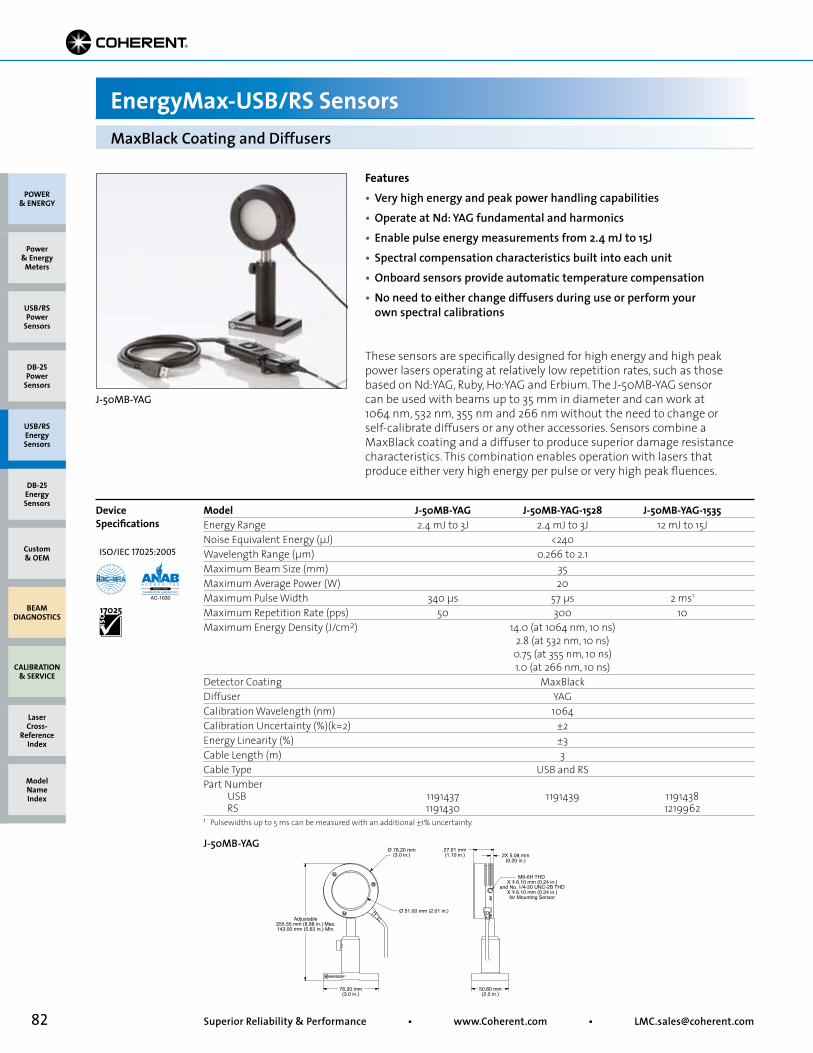
82 Superior Reliability & Performance • www.Coherent.com • [email protected]
Features• Very high energy and peak power handling capabilities• Operate at Nd: YAG fundamental and harmonics• Enable pulse energy measurements from 2.4 mJ to 15J• Spectral compensation characteristics built into each unit• Onboard sensors provide automatic temperature compensation• No need to either change diffusers during use or perform your own spectral calibrations
J-50MB-YAG
Adjustable255.55 mm (8.88 in.) Max.143.00 mm (5.63 in.) Min.
M6-6H THD X 6.10 mm (0.24 in.)
and No. 1/4-20 UNC-2B THDX 6.10 mm (0.24 in.)for Mounting Sensor
Ø 76.20 mm(3.0 in.)
Ø 51.00 mm (2.01 in.)
27.91 mm(1.10 in.)
76.20 mm(3.0 in.)
50.80 mm(2.0 in.)
2X 5.08 mm(0.20 in.)
J-50MB-YAG
MaxBlack Coating and Diffusers
EnergyMax-USB/RS Sensors
Device Specifications
J-50MB-YAG
POWER & ENERGY
Custom & OEM
BEAM DIAGNOSTICS
CALIBRATION & SERVICE
Power & Energy
Meters
Laser Cross-
Reference Index
Model Name Index
DB-25Energy Sensors
USB/RSEnergy Sensors
DB-25Power
Sensors
USB/RSPower
Sensors
These sensors are specifically designed for high energy and high peak power lasers operating at relatively low repetition rates, such as those based on Nd:YAG, Ruby, Ho:YAG and Erbium. The J-50MB-YAG sensor can be used with beams up to 35 mm in diameter and can work at 1064 nm, 532 nm, 355 nm and 266 nm without the need to change or self-calibrate diffusers or any other accessories. Sensors combine a MaxBlack coating and a diffuser to produce superior damage resistance characteristics. This combination enables operation with lasers that produce either very high energy per pulse or very high peak fluences.
Model J-50MB-YAG J-50MB-YAG-1528 J-50MB-YAG-1535Energy Range 2.4 mJ to 3J 2.4 mJ to 3J 12 mJ to 15JNoise Equivalent Energy (µJ) <240Wavelength Range (µm) 0.266 to 2.1Maximum Beam Size (mm) 35Maximum Average Power (W) 20Maximum Pulse Width 340 µs 57 µs 2 ms1
Maximum Repetition Rate (pps) 50 300 10Maximum Energy Density (J/cm2) 14.0 (at 1064 nm, 10 ns) 2.8 (at 532 nm, 10 ns) 0.75 (at 355 nm, 10 ns) 1.0 (at 266 nm, 10 ns)Detector Coating MaxBlackDiffuser YAGCalibration Wavelength (nm) 1064Calibration Uncertainty (%)(k=2) ±2Energy Linearity (%) ±3Cable Length (m) 3Cable Type USB and RSPart Number USB 1191437 1191439 1191438 RS 1191430 12199621 Pulsewidths up to 5 ms can be measured with an additional ±1% uncertainty.
ISO/IEC 17025:2005
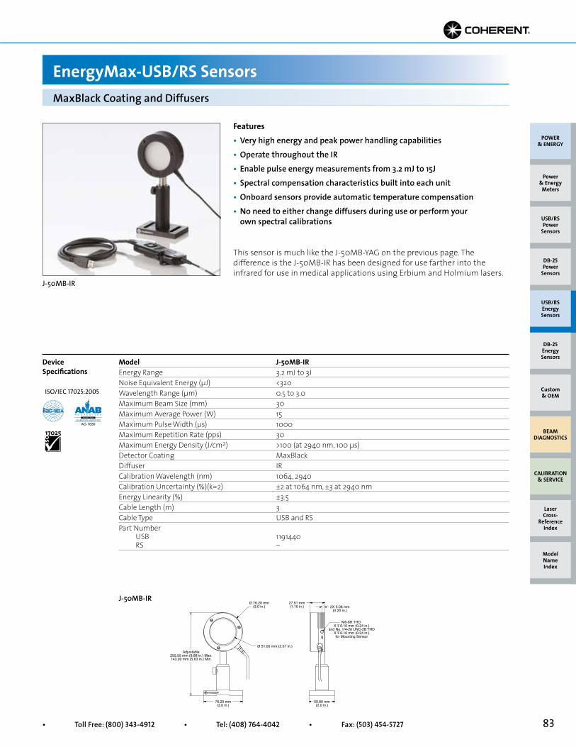
83• Toll Free: (800) 343-4912 • Tel: (408) 764-4042 • Fax: (503) 454-5727
Features• Very high energy and peak power handling capabilities• Operate throughout the IR• Enable pulse energy measurements from 3.2 mJ to 15J• Spectral compensation characteristics built into each unit• Onboard sensors provide automatic temperature compensation• No need to either change diffusers during use or perform your own spectral calibrations
J-50MB-YAG
Adjustable255.55 mm (8.88 in.) Max.143.00 mm (5.63 in.) Min.
M6-6H THD X 6.10 mm (0.24 in.)
and No. 1/4-20 UNC-2B THDX 6.10 mm (0.24 in.)for Mounting Sensor
Ø 76.20 mm(3.0 in.)
Ø 51.00 mm (2.01 in.)
27.91 mm(1.10 in.)
76.20 mm(3.0 in.)
50.80 mm(2.0 in.)
2X 5.08 mm(0.20 in.)
J-50MB-IR
MaxBlack Coating and Diffusers
EnergyMax-USB/RS Sensors
Device Specifications
J-50MB-IR
POWER & ENERGY
Custom & OEM
BEAM DIAGNOSTICS
CALIBRATION & SERVICE
Power & Energy
Meters
Laser Cross-
Reference Index
Model Name Index
DB-25Energy Sensors
USB/RSEnergy Sensors
DB-25Power
Sensors
USB/RSPower
Sensors
This sensor is much like the J-50MB-YAG on the previous page. The difference is the J-50MB-IR has been designed for use farther into the infrared for use in medical applications using Erbium and Holmium lasers.
Model J-50MB-IREnergy Range 3.2 mJ to 3JNoise Equivalent Energy (µJ) <320Wavelength Range (µm) 0.5 to 3.0Maximum Beam Size (mm) 30Maximum Average Power (W) 15Maximum Pulse Width (µs) 1000Maximum Repetition Rate (pps) 30Maximum Energy Density (J/cm2) >100 (at 2940 nm, 100 µs)Detector Coating MaxBlackDiffuser IRCalibration Wavelength (nm) 1064, 2940Calibration Uncertainty (%)(k=2) ±2 at 1064 nm, ±3 at 2940 nmEnergy Linearity (%) ±3.5Cable Length (m) 3Cable Type USB and RSPart Number USB 1191440 RS –
ISO/IEC 17025:2005
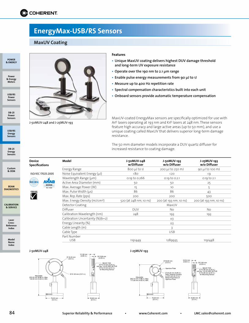
84 Superior Reliability & Performance • www.Coherent.com • [email protected]
POWER & ENERGY
Custom & OEM
BEAM DIAGNOSTICS
CALIBRATION & SERVICE
Power & Energy
Meters
Laser Cross-
Reference Index
Model Name Index
DB-25Energy Sensors
USB/RSEnergy Sensors
DB-25Power
Sensors
USB/RSPower
Sensors
Adjustable225.55 mm (8.88 in.) Max.143.00 mm (5.63 in.) Min.
M6-6H THD X 6.10 mm (0.24 in.)
and No. 1/4-20 UNC-2B THDX 6.10 mm (0.24 in.)for Mounting Sensor
Ø 76.20 mm(3.0 in.)
Ø 51.00 mm (2.01 in.)
21.56 mm(0.85 in.)
76.20 mm(3.0 in.)
50.80 mm(2.0 in.)
2X 5.08 mm(0.20 in.)
Adjustable200.15 mm (7.88 in.) Max.117.60 mm (4.63 in.) Min.
Aperture Plate M6-6H THD X 5.08 mm (0.20 in.)
and No. 1/4-20 UNC-2B THDX 5.08 mm (0.20 in.)for Mounting Sensor
Ø 50.80 mm(2.0 in.)
Ø 25.25 mm (0.99 in.)Note: Detector Surface is 3.81 mm (0.15 in.) Below Front Face of Aperture Plate
16.54 mm(0.65 in.)
76.20 mm(3.0 in.)
50.80 mm(2.0 in.)
2X 5.84 mm(0.23 in.)
MaxUV Coating
EnergyMax-USB/RS Sensors
Features• Unique MaxUV coating delivers highest DUV damage threshold and long-term UV exposure resistance• Operate over the 190 nm to 2.1 µm range• Enable pulse energy measurements from 90 µJ to 1J• Measure up to 400 Hz repetition rate• Spectral compensation characteristics built into each unit• Onboard sensors provide automatic temperature compensation
Model J-50MUV-248 J-50MUV-193 J-25MUV-193 w/Diffuser w/o Diffuser w/o DiffuserEnergy Range 800 µJ to 1J 200 µJ to 250 mJ 90 µJ to 100 mJNoise Equivalent Energy (µJ) <80 <20 <9Wavelength Range (µm) 0.19 to 0.266 0.19 to 0.2.1 0.19 to 2.1Active Area Diameter (mm) 50 50 25Max. Average Power (W) 15 10 5Max. Pulse Width (µs) 86 86 43Max. Rep. Rate (pps) 200 200 500Max. Energy Density (mJ/cm2) 520 (at 248 nm, 10 ns) 200 (at 193 nm, 10 ns) 200 (at 193 nm, 10 ns)Detector Coating MaxUVDiffuser DUV No NoCalibration Wavelength (nm) 248 193 193Calibration Uncertainty (%)(k=2) ±3Energy Linearity (%) ±3Cable Length (m) 3Cable Type USBPart Number USB 1191449 1289935 1191448
Device Specifications
MaxUV-coated EnergyMax sensors are specifically optimized for use with ArF lasers operating at 193 nm and KrF lasers at 248 nm. These sensors feature high accuracy and large active areas (up to 50 mm), and use a unique coating called MaxUV that delivers superior long-term damage resistance.
The 50 mm diameter models incorporate a DUV quartz diffuser for increased resistance to coating damage.
J-50MUV-248 J-25MUV-193
J-50MUV-248 and J-25MUV-193
ISO/IEC 17025:2005
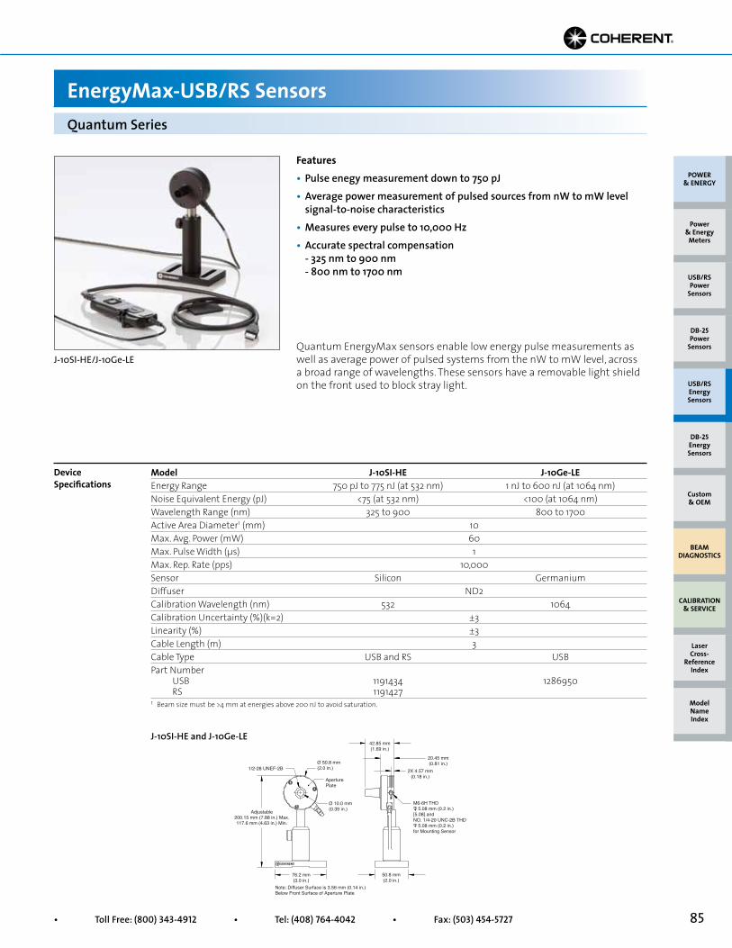
85• Toll Free: (800) 343-4912 • Tel: (408) 764-4042 • Fax: (503) 454-5727
POWER & ENERGY
Custom & OEM
BEAM DIAGNOSTICS
CALIBRATION & SERVICE
Power & Energy
Meters
Laser Cross-
Reference Index
Model Name Index
DB-25Energy Sensors
USB/RSEnergy Sensors
DB-25Power
Sensors
USB/RSPower
Sensors
Device Specifications
Model J-10SI-HE J-10Ge-LE Energy Range 750 pJ to 775 nJ (at 532 nm) 1 nJ to 600 nJ (at 1064 nm)Noise Equivalent Energy (pJ) <75 (at 532 nm) <100 (at 1064 nm)Wavelength Range (nm) 325 to 900 800 to 1700Active Area Diameter1 (mm) 10Max. Avg. Power (mW) 60Max. Pulse Width (µs) 1Max. Rep. Rate (pps) 10,000Sensor Silicon GermaniumDiffuser ND2Calibration Wavelength (nm) 532 1064Calibration Uncertainty (%)(k=2) ±3Linearity (%) ±3Cable Length (m) 3Cable Type USB and RS USBPart Number USB 1191434 1286950 RS 1191427
Quantum EnergyMax sensors enable low energy pulse measurements as well as average power of pulsed systems from the nW to mW level, across a broad range of wavelengths. These sensors have a removable light shield on the front used to block stray light.
Quantum Series
EnergyMax-USB/RS Sensors
Features• Pulse enegy measurement down to 750 pJ• Average power measurement of pulsed sources from nW to mW level signal-to-noise characteristics• Measures every pulse to 10,000 Hz• Accurate spectral compensation - 325 nm to 900 nm - 800 nm to 1700 nm
Ø 50.8 mm(2.0 in.)
Note: Diffuser Surface is 3.56 mm (0.14 in.)Below Front Surface of Aperture Plate
42.85 mm(1.69 in.)
20.45 mm(0.81 in.)
76.2 mm(3.0 in.)
50.8 mm(2.0 in.)
2X 4.57 mm(0.18 in.)
Ø 10.0 mm(0.39 in.)
AperturePlate
M6-6H THD 5.08 mm (0.2 in.)[5.08] andNO. 1/4-20 UNC-2B THD 5.08 mm (0.2 in.)for Mounting Sensor
Adjustable200.15 mm (7.88 in.) Max.117.6 mm (4.63 in.) Min.
1/2-28 UNEF-2B
J-10SI-HE and J-10Ge-LE
J-10SI-HE/J-10Ge-LE
1 Beam size must be >4 mm at energies above 200 nJ to avoid saturation.
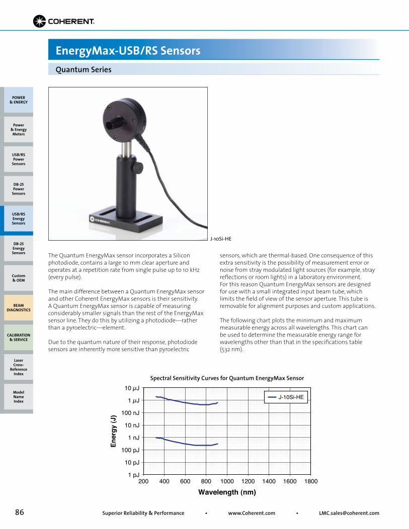
86 Superior Reliability & Performance • www.Coherent.com • [email protected]
Quantum Series
EnergyMax-USB/RS Sensors
The Quantum EnergyMax sensor incorporates a Silicon photodiode, contains a large 10 mm clear aperture and operates at a repetition rate from single pulse up to 10 kHz (every pulse).
The main difference between a Quantum EnergyMax sensor and other Coherent EnergyMax sensors is their sensitivity. A Quantum EnergyMax sensor is capable of measuring considerably smaller signals than the rest of the EnergyMax sensor line. They do this by utilizing a photodiode—rather than a pyroelectric—element.
Due to the quantum nature of their response, photodiode sensors are inherently more sensitive than pyroelectric
sensors, which are thermal-based. One consequence of this extra sensitivity is the possibility of measurement error or noise from stray modulated light sources (for example, stray reflections or room lights) in a laboratory environment. For this reason Quantum EnergyMax sensors are designed for use with a small integrated input beam tube, which limits the field of view of the sensor aperture. This tube is removable for alignment purposes and custom applications.
The following chart plots the minimum and maximum measurable energy across all wavelengths. This chart can be used to determine the measurable energy range for wavelengths other than that in the specifications table (532 nm).
Spectral Sensitivity Curves for Quantum EnergyMax Sensor
Wavelength (nm)
Ener
gy (J
)
1 pJ200 1800
10 µJ
10 pJ
100 pJ
1 nJ
10 nJ
100 nJ
1 µJ
400 600 800 1000 1200 1400 1600
J-10Si-HE
POWER & ENERGY
Custom & OEM
BEAM DIAGNOSTICS
CALIBRATION & SERVICE
Power & Energy
Meters
Laser Cross-
Reference Index
Model Name Index
DB-25Energy Sensors
USB/RSEnergy Sensors
DB-25Power
Sensors
USB/RSPower
Sensors
J-10Si-HE
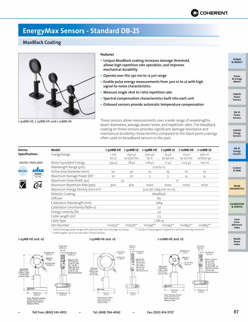
87• Toll Free: (800) 343-4912 • Tel: (408) 764-4042 • Fax: (503) 454-5727
Model J-50MB-HE J-50MB-LE J-25MB-HE J-25MB-LE J-10MB-HE J-10MB-LEEnergy Range 1 mJ 250 µJ 500 µJ 25 µJ 10 µJ 300 nJ to 2J to 500 mJ to 1J to 50 mJ to 20 mJ to 600 µJNoise Equivalent Energy <33 µJ <8 µJ <16 µJ <1 µJ <0.5 µJ <20 nJWavelength Range (µm) 0.19 to 12Active Area Diameter (mm) 50 50 25 25 10 10Maximum Average Power (W)1 10 10 5 5 4 4Maximum Pulse Width (µs) 57 17Maximum Repetition Rate (pps) 300 300 1000 1000 1000 1000Maximum Energy Density (mJ/cm2) 500 (at 1064 nm, 10 ns)Detector Coating MaxBlackDiffuser NoCalibration Wavelength (nm) 1064Calibration Uncertainty (%)(k=2) ±2Energy Linearity (%) ±3Cable Length (m)2 2.5Cable Type J DB-25Part Number 1110573** 1110576** 1110746** 1110743** 1110843** 1110855**
These sensors allow measurements over a wide range of wavelengths, beam diameters, average power levels, and repetition rates. The MaxBlack coating on these sensors provides significant damage resistance and mechanical durability characteristics compared to the black paint coatings often used on broadband sensors in the past.
Adjustable200.15 mm
(7.88 in.) Max.117.60 mm
(4.63 in.) Min.
Aperture Plate
Ø 50.80 mm(2.0 in.)
Ø 25.25 mm (0.99 in.)
16.54 mm(0.65 in.)
76.20 mm(3.0 in.)
50.80 mm(2.0 in.)
2X 5.84 mm(0.23 in.)
M6-6H THD X 5.08 mm (0.20 in.) and No. 1/4-20 UNC-2B THDX 5.08 mm (0.20 in.) for Mounting Sensor
Note: Detector Surface is 3.81 mm (0.15 in.) Below Front Face of Aperture Plate
J-25MB-HE and -LE
Adjustable225.55 mm
(8.88 in.) Max.143.00 mm
(5.63 in.) Min.
Ø 76.20 mm(3.0 in.)
Ø 50.20 mm (1.98 in.)
16.38 mm(0.65 in.)
76.2 mm(3.0 in.)
50.8 mm(2.0 in.)
2X 5.08 mm(0.20 in.)
M6-6H THD X 6.10 mm (0.24 in.) and No. 1/4-20 UNC-2B THDX 6.10 mm (0.24 in.) for Mounting Sensor
Note: Detector Surface is 3.81 mm (0.15 in.) Below Front Face of Aperture Plate
J-50MB-HE and -LE
Adjustable189.99 mm
(7.48 in.) Max.107.44 mm
(4.23 in.) Min.
Aperture Plate
Ø 40.64 mm(1.6 in.)
Ø 10.5 mm (0.41 in.)
15.75 mm(0.62 in.)
50.80 mm(2.0 in.)
76.20 mm(3.0 in.)
2X 5.08 mm(0.2 in.)
M4 X 17.78 mm (0.7 in.) THD X 4.57 mm (0.18 in.) and No. 8-32 UNC-2B THD X 6.35 mm (0.25 in.) for Mounting Sensor
Note: Detector Surface is 3.81 mm (0.15 in.) Below Front Face of Aperture Plate
J-10MB-HE and -LE
MaxBlack Coating
EnergyMax Sensors - Standard DB-25
Device Specifications
Features• Unique MaxBlack coating increases damage threshold, allows high repetition rate operation, and improves mechanical durability• Operate over the 190 nm to 12 µm range• Enable pulse energy measurements from 300 nJ to 2J with high signal-to-noise characteristics• Measure single shot to 1 kHz repetition rate• Spectral compensation characteristics built into each unit• Onboard sensors provide automatic temperature compensation
J-50MB-HE, J-25MB-HE and J-10MB-HE
1 Extend average power range with optional heat sink. See page 75 and 94.2 Cable lengths up to 10m possible. Contact factory.
POWER & ENERGY
Custom & OEM
BEAM DIAGNOSTICS
CALIBRATION & SERVICE
Power & Energy
Meters
Laser Cross-
Reference Index
Model Name Index
DB-25Energy Sensors
USB/RSEnergy Sensors
DB-25Power
Sensors
USB/RSPower
Sensors
** C24 Quick Ship program: eligible for next business day shipment.
ISO/IEC 17025:2005
**
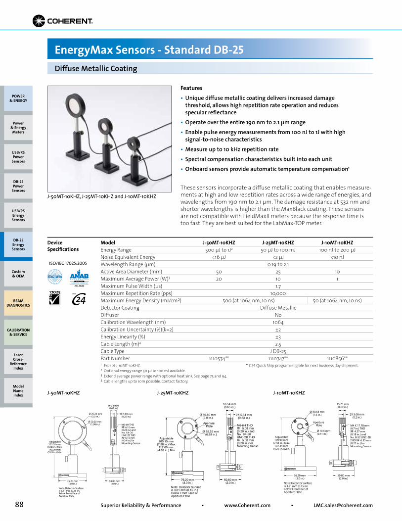
88 Superior Reliability & Performance • www.Coherent.com • [email protected]
Model J-50MT-10KHZ J-25MT-10KHZ J-10MT-10KHZEnergy Range 500 µJ to 1J2 50 µJ to 100 mJ 100 nJ to 200 µJNoise Equivalent Energy <16 µJ <2 µJ <10 nJWavelength Range (µm) 0.19 to 2.1Active Area Diameter (mm) 50 25 10Maximum Average Power (W)3 20 10 1Maximum Pulse Width (µs) 1.7Maximum Repetition Rate (pps) 10,000Maximum Energy Density (mJ/cm2) 500 (at 1064 nm, 10 ns) 50 (at 1064 nm, 10 ns)Detector Coating Diffuse MetallicDiffuser NoCalibration Wavelength (nm) 1064Calibration Uncertainty (%)(k=2) ±2Energy Linearity (%) ±3Cable Length (m)4 2.5Cable Type J DB-25Part Number 1110574** 1110747** 1110856**
These sensors incorporate a diffuse metallic coating that enables measure-ments at high and low repetition rates across a wide range of energies, and wavelengths from 190 nm to 2.1 µm. The damage resistance at 532 nm and shorter wavelengths is higher than the MaxBlack coating. These sensors are not compatible with FieldMaxII meters because the response time is too fast. They are best suited for the LabMax-TOP meter.
Ø 76.20 mm(3.0 in.)
16.38 mm(0.65 in.)
Ø 50.20 mm (1.98 in.)
50.80 mm(2.0 in.)
76.20 mm(3.0 in.)
Adjustable225.55 mm
(8.88 in.) Max.143.00 mm
(5.63 in.) Min.
2X 5.08 mm(0.20 in.)
M6-6H THD X 6.10 mm (0.24 in.) and No. 1/4-20 UNC-2B THDX 6.10 mm (0.24 in.) for Mounting Sensor
Note: Detector Surface is 3.81 mm (0.15 in.) Below Front Face of Aperture Plate
J-50MT-10KHZ
Aperture Plate
Ø 50.80 mm(2.0 in.)
16.54 mm(0.65 in.)
Ø 25.25 mm (0.99 in.)
50.80 mm(2.0 in.)
76.20 mm(3.0 in.)
Adjustable200.15 mm
(7.88 in.) Max.117.60 mm
(4.63 in.) Min.
2X 5.84 mm(0.23 in.)
M6-6H THD X 5.08 mm (0.20 in.) and No. 1/4-20 UNC-2B THDX 5.08 mm (0.20 in.) for Mounting Sensor
Note: Detector Surface is 3.81 mm (0.15 in.) Below Front Face of Aperture Plate
J-25MT-10KHZ
Adjustable189.99 mm
(7.48 in.) Max.107.44 mm
(4.23 in.) Min.
Aperture Plate
Ø 40.64 mm(1.6 in.)
Ø 10.5 mm (0.41 in.)
15.75 mm(0.62 in.)
50.80 mm(2.0 in.)
76.20 mm(3.0 in.)
2X 5.08 mm(0.2 in.)
M4 X 17.78 mm (0.7 in.) THD X 4.57 mm (0.18 in.) and No. 8-32 UNC-2B THD X 6.35 mm (0.25 in.) for Mounting Sensor
Note: Detector Surface is 3.81 mm (0.15 in.) Below Front Face of Aperture Plate
J-10MT-10KHZ
Diffuse Metallic Coating
EnergyMax Sensors - Standard DB-25
Device Specifications
1 Except J-10MT-10KHZ.2 Optional energy range 50 µJ to 100 mJ available. 3 Extend average power range with optional heat sink. See page 75 and 94.4 Cable lengths up to 10m possible. Contact factory.
Features• Unique diffuse metallic coating delivers increased damage threshold, allows high repetition rate operation and reduces specular reflectance• Operate over the entire 190 nm to 2.1 µm range• Enable pulse energy measurements from 100 nJ to 1J with high signal-to-noise characteristics• Measure up to 10 kHz repetition rate• Spectral compensation characteristics built into each unit• Onboard sensors provide automatic temperature compensation1
J-50MT-10KHZ, J-25MT-10KHZ and J-10MT-10KHZ
POWER & ENERGY
Custom & OEM
BEAM DIAGNOSTICS
CALIBRATION & SERVICE
Power & Energy
Meters
Laser Cross-
Reference Index
Model Name Index
DB-25Energy Sensors
USB/RSEnergy Sensors
DB-25Power
Sensors
USB/RSPower
Sensors
** C24 Quick Ship program: eligible for next business day shipment.
ISO/IEC 17025:2005
**
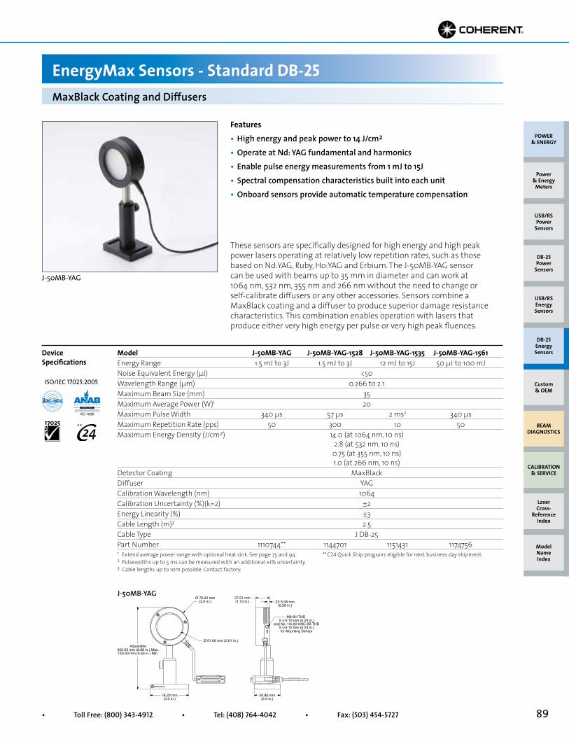
89• Toll Free: (800) 343-4912 • Tel: (408) 764-4042 • Fax: (503) 454-5727
POWER & ENERGY
Custom & OEM
BEAM DIAGNOSTICS
CALIBRATION & SERVICE
Power & Energy
Meters
Laser Cross-
Reference Index
Model Name Index
DB-25Energy Sensors
USB/RSEnergy Sensors
DB-25Power
Sensors
USB/RSPower
Sensors
J-50MB-YAG
Adjustable255.55 mm (8.88 in.) Max.143.00 mm (5.63 in.) Min.
M6-6H THD X 6.10 mm (0.24 in.)
and No. 1/4-20 UNC-2B THDX 6.10 mm (0.24 in.)for Mounting Sensor
Ø 76.20 mm(3.0 in.)
Ø 51.00 mm (2.01 in.)
27.91 mm(1.10 in.)
76.20 mm(3.0 in.)
50.80 mm(2.0 in.)
2X 5.08 mm(0.20 in.)
J-50MB-YAG
MaxBlack Coating and Diffusers
EnergyMax Sensors - Standard DB-25
These sensors are specifically designed for high energy and high peak power lasers operating at relatively low repetition rates, such as those based on Nd:YAG, Ruby, Ho:YAG and Erbium. The J-50MB-YAG sensor can be used with beams up to 35 mm in diameter and can work at 1064 nm, 532 nm, 355 nm and 266 nm without the need to change or self-calibrate diffusers or any other accessories. Sensors combine a MaxBlack coating and a diffuser to produce superior damage resistance characteristics. This combination enables operation with lasers that produce either very high energy per pulse or very high peak fluences.
Features• High energy and peak power to 14 J/cm2
• Operate at Nd: YAG fundamental and harmonics• Enable pulse energy measurements from 1 mJ to 15J• Spectral compensation characteristics built into each unit• Onboard sensors provide automatic temperature compensation
Model J-50MB-YAG J-50MB-YAG-1528 J-50MB-YAG-1535 J-50MB-YAG-1561Energy Range 1.5 mJ to 3J 1.5 mJ to 3J 12 mJ to 15J 50 µJ to 100 mJNoise Equivalent Energy (µJ) <50Wavelength Range (µm) 0.266 to 2.1Maximum Beam Size (mm) 35Maximum Average Power (W)1 20Maximum Pulse Width 340 µs 57 µs 2 ms2 340 µsMaximum Repetition Rate (pps) 50 300 10 50Maximum Energy Density (J/cm2) 14.0 (at 1064 nm, 10 ns) 2.8 (at 532 nm, 10 ns) 0.75 (at 355 nm, 10 ns) 1.0 (at 266 nm, 10 ns)Detector Coating MaxBlackDiffuser YAGCalibration Wavelength (nm) 1064Calibration Uncertainty (%)(k=2) ±2Energy Linearity (%) ±3Cable Length (m)3 2.5Cable Type J DB-25Part Number 1110744** 1144701 1151431 1174756
Device Specifications
1 Extend average power range with optional heat sink. See page 75 and 94.2 Pulsewidths up to 5 ms can be measured with an additional ±1% uncertainty. 3 Cable lengths up to 10m possible. Contact factory.
J-50MB-YAG
** C24 Quick Ship program: eligible for next business day shipment.
ISO/IEC 17025:2005
**
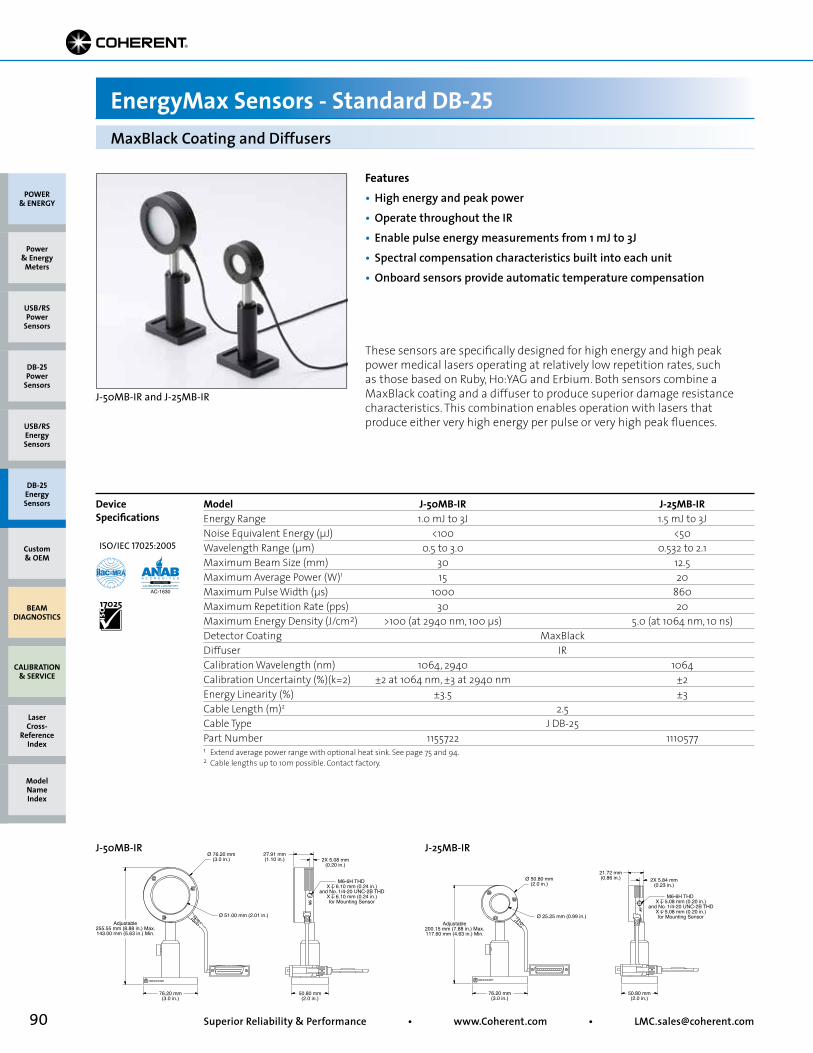
90 Superior Reliability & Performance • www.Coherent.com • [email protected]
J-50MB-YAG
Adjustable255.55 mm (8.88 in.) Max.143.00 mm (5.63 in.) Min.
M6-6H THD X 6.10 mm (0.24 in.)
and No. 1/4-20 UNC-2B THDX 6.10 mm (0.24 in.)for Mounting Sensor
Ø 76.20 mm(3.0 in.)
Ø 51.00 mm (2.01 in.)
27.91 mm(1.10 in.)
76.20 mm(3.0 in.)
50.80 mm(2.0 in.)
2X 5.08 mm(0.20 in.)
J-25MB-IR
Adjustable200.15 mm (7.88 in.) Max.117.60 mm (4.63 in.) Min.
M6-6H THD X 5.08 mm (0.20 in.)
and No. 1/4-20 UNC-2B THDX 5.08 mm (0.20 in.)for Mounting Sensor
Ø 50.80 mm(2.0 in.)
Ø 25.25 mm (0.99 in.)
21.72 mm(0.86 in.)
76.20 mm(3.0 in.)
50.80 mm(2.0 in.)
2X 5.84 mm(0.23 in.)
J-50MB-IR J-25MB-IR
MaxBlack Coating and Diffusers
EnergyMax Sensors - Standard DB-25
These sensors are specifically designed for high energy and high peak power medical lasers operating at relatively low repetition rates, such as those based on Ruby, Ho:YAG and Erbium. Both sensors combine a MaxBlack coating and a diffuser to produce superior damage resistance characteristics. This combination enables operation with lasers that produce either very high energy per pulse or very high peak fluences.
Features• High energy and peak power• Operate throughout the IR• Enable pulse energy measurements from 1 mJ to 3J• Spectral compensation characteristics built into each unit• Onboard sensors provide automatic temperature compensation
Model J-50MB-IR J-25MB-IREnergy Range 1.0 mJ to 3J 1.5 mJ to 3JNoise Equivalent Energy (µJ) <100 <50Wavelength Range (µm) 0.5 to 3.0 0.532 to 2.1Maximum Beam Size (mm) 30 12.5Maximum Average Power (W)1 15 20Maximum Pulse Width (µs) 1000 860Maximum Repetition Rate (pps) 30 20Maximum Energy Density (J/cm2) >100 (at 2940 nm, 100 µs) 5.0 (at 1064 nm, 10 ns)Detector Coating MaxBlack Diffuser IR Calibration Wavelength (nm) 1064, 2940 1064Calibration Uncertainty (%)(k=2) ±2 at 1064 nm, ±3 at 2940 nm ±2Energy Linearity (%) ±3.5 ±3Cable Length (m)2 2.5 Cable Type J DB-25 Part Number 1155722 1110577
Device Specifications
1 Extend average power range with optional heat sink. See page 75 and 94.2 Cable lengths up to 10m possible. Contact factory.
J-50MB-IR and J-25MB-IR
POWER & ENERGY
Custom & OEM
BEAM DIAGNOSTICS
CALIBRATION & SERVICE
Power & Energy
Meters
Laser Cross-
Reference Index
Model Name Index
DB-25Energy Sensors
USB/RSEnergy Sensors
DB-25Power
Sensors
USB/RSPower
Sensors
ISO/IEC 17025:2005
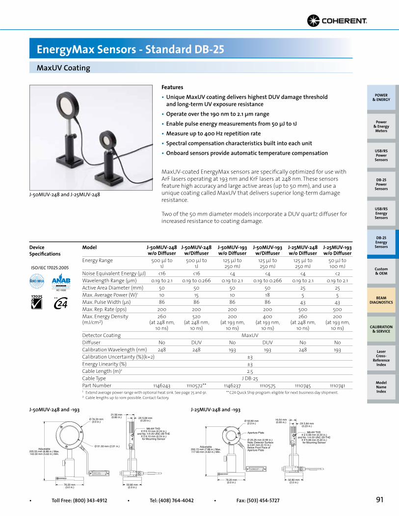
91• Toll Free: (800) 343-4912 • Tel: (408) 764-4042 • Fax: (503) 454-5727
Adjustable225.55 mm (8.88 in.) Max.143.00 mm (5.63 in.) Min.
M6-6H THD X 6.10 mm (0.24 in.)
and No. 1/4-20 UNC-2B THDX 6.10 mm (0.24 in.)for Mounting Sensor
Ø 76.20 mm(3.0 in.)
Ø 51.00 mm (2.01 in.)
21.56 mm(0.85 in.)
76.20 mm(3.0 in.)
50.80 mm(2.0 in.)
2X 5.08 mm(0.20 in.)
Adjustable200.15 mm (7.88 in.) Max.117.60 mm (4.63 in.) Min.
Aperture Plate M6-6H THD X 5.08 mm (0.20 in.)
and No. 1/4-20 UNC-2B THDX 5.08 mm (0.20 in.)for Mounting Sensor
Ø 50.80 mm(2.0 in.)
Ø 25.25 mm (0.99 in.)Note: Detector Surface is 3.81 mm (0.15 in.) Below Front Face of Aperture Plate
16.54 mm(0.65 in.)
76.20 mm(3.0 in.)
50.80 mm(2.0 in.)
2X 5.84 mm(0.23 in.)
MaxUV Coating
EnergyMax Sensors - Standard DB-25
Features• Unique MaxUV coating delivers highest DUV damage threshold and long-term UV exposure resistance• Operate over the 190 nm to 2.1 µm range• Enable pulse energy measurements from 50 µJ to 1J• Measure up to 400 Hz repetition rate• Spectral compensation characteristics built into each unit• Onboard sensors provide automatic temperature compensation
Model J-50MUV-248 J-50MUV-248 J-50MUV-193 J-50MUV-193 J-25MUV-248 J-25MUV-193 w/o Diffuser w/Diffuser w/o Diffuser w/Diffuser w/o Diffuser w/o DiffuserEnergy Range 500 µJ to 500 µJ to 125 µJ to 125 µJ to 125 µJ to 50 µJ to 1J 1J 250 mJ 250 mJ 250 mJ 100 mJNoise Equivalent Energy (µJ) <16 <16 <4 <4 <4 <2Wavelength Range (µm) 0.19 to 2.1 0.19 to 0.266 0.19 to 2.1 0.19 to 0.266 0.19 to 2.1 0.19 to 2.1Active Area Diameter (mm) 50 50 50 50 25 25Max. Average Power (W)1 10 15 10 18 5 5Max. Pulse Width (µs) 86 86 86 86 43 43Max. Rep. Rate (pps) 200 200 200 200 500 500Max. Energy Density 260 520 200 400 260 200(mJ/cm2) (at 248 nm, (at 248 nm, (at 193 nm, (at 193 nm, (at 248 nm, (at 193 nm, 10 ns) 10 ns) 10 ns) 10 ns) 10 ns) 10 ns)Detector Coating MaxUVDiffuser No DUV No DUV No NoCalibration Wavelength (nm) 248 248 193 193 248 193Calibration Uncertainty (%)(k=2) ±3Energy Linearity (%) ±3Cable Length (m)2 2.5Cable Type J DB-25Part Number 1146243 1110572** 1146237 1110575 1110745 1110741
Device Specifications
MaxUV-coated EnergyMax sensors are specifically optimized for use with ArF lasers operating at 193 nm and KrF lasers at 248 nm. These sensors feature high accuracy and large active areas (up to 50 mm), and use a unique coating called MaxUV that delivers superior long-term damage resistance.
Two of the 50 mm diameter models incorporate a DUV quartz diffuser for increased resistance to coating damage.
J-50MUV-248 and -193 J-25MUV-248 and -193
1 Extend average power range with optional heat sink. See page 75 and 91.2 Cable lengths up to 10m possible. Contact factory.
J-50MUV-248 and J-25MUV-248
POWER & ENERGY
Custom & OEM
BEAM DIAGNOSTICS
CALIBRATION & SERVICE
Power & Energy
Meters
Laser Cross-
Reference Index
Model Name Index
DB-25Energy Sensors
USB/RSEnergy Sensors
DB-25Power
Sensors
USB/RSPower
Sensors
** C24 Quick Ship program: eligible for next business day shipment.
ISO/IEC 17025:2005
**
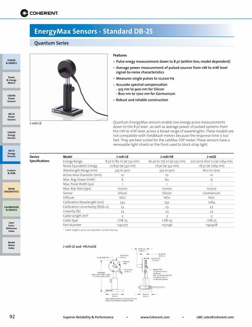
92 Superior Reliability & Performance • www.Coherent.com • [email protected]
Model J-10SI-LE J-10SI-HE J-10GEEnergy Range 8 pJ to 80 nJ (at 532 nm) 60 pJ to 775 nJ (at 532 nm) 200 pJ to 600 nJ (at 1064 nm)Noise Equivalent Energy <0.8 pJ (at 532 nm) <6 pJ (at 532 nm) <8 pJ (at 1064 nm)Wavelength Range (nm) 325 to 900 325 to 900 800 to 1700Active Area Diameter (mm) 10 10 10Max. Avg. Power (mW) 6 60 15Max. Pulse Width (µs) 1 1 1Max. Rep. Rate (pps) 10,000 10,000 10,000Sensor Silicon Silicon GermaniumDiffuser ND2 ND2 ND2Calibration Wavelength (nm) 532 532 1064Calibration Uncertainty (%)(k=2) ±3 ±3 ±3Linearity (%) ±3 ±3 ±3Cable Length (m)1 3 3 3Cable Type J DB-25 J DB-25 J DB-25Part Number 1140727 1150146 1140408
Quantum EnergyMax sensors enable low energy pulse measurements down to the 8 pJ level , as well as average power of pulsed systems from the nW to mW level, across a broad range of wavelengths. These models are not compatible with FieldMaxII meters because the response time is too fast. They are best suited for the LabMax-TOP meter. These sensors have a removable light shield on the front used to block stray light.
Quantum Series
EnergyMax Sensors - Standard DB-25
Device Specifications
Features• Pulse enegy measurement down to 8 pJ (within line; model dependent)• Average power measurement of pulsed sources from nW to mW level signal-to-noise characteristics• Measures single pulses to 10,000 Hz• Accurate spectral compensation - 325 nm to 900 nm for Silicon - 800 nm to 1700 nm for Germanium• Robust and reliable construction
Ø 50.8 mm(2.0 in.)
Note: Diffuser Surface is 3.56 mm (0.14 in.)Below Front Surface of Aperture Plate
42.85 mm(1.69 in.)
20.45 mm(0.81 in.)
76.2 mm(3.0 in.)
50.8 mm(2.0 in.)
2X 4.57 mm(0.18 in.)
Ø 10.0 mm(0.39 in.)
AperturePlate
M6-6H THD 5.08 mm (0.2 in.)[5.08] andNO. 1/4-20 UNC-2B THD 5.08 mm (0.2 in.)for Mounting Sensor
Adjustable200.15 mm (7.88 in.) Max.117.6 mm (4.63 in.) Min.
1/2-28 UNEF-2B
J-10SI-LE and -HE/J10GE
1 Cable lengths up to 10m possible. Contact factory.
J-10SI-LE
POWER & ENERGY
Custom & OEM
BEAM DIAGNOSTICS
CALIBRATION & SERVICE
Power & Energy
Meters
Laser Cross-
Reference Index
Model Name Index
DB-25Energy Sensors
USB/RSEnergy Sensors
DB-25Power
Sensors
USB/RSPower
Sensors
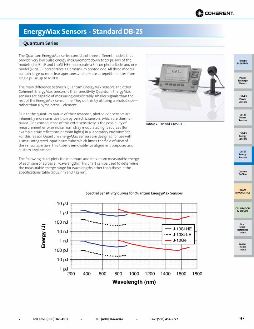
93• Toll Free: (800) 343-4912 • Tel: (408) 764-4042 • Fax: (503) 454-5727
Wavelength (nm)
Ener
gy (J
)
1 pJ200 1800
10 µJ
10 pJ
100 pJ
1 nJ
10 nJ
100 nJ
1 µJ
400 600 800 1000 1200 1400 1600
J-10Si-LEJ-10Si-HE
J-10Ge
Quantum Series
EnergyMax Sensors - Standard DB-25
The Quantum EnergyMax series consists of three different models that provide very low pulse energy measurement down to 20 pJ. Two of the models (J-10SI-LE and J-10SI-HE) incorporate a Silicon photodiode, and one model (J-10GE) incorporates a Germanium photodiode. All three models contain large 10 mm clear apertures and operate at repetition rates from single pulse up to 10 kHz.
The main difference between Quantum EnergyMax sensors and other Coherent EnergyMax sensors is their sensitivity. Quantum EnergyMax sensors are capable of measuring considerably smaller signals than the rest of the EnergyMax sensor line. They do this by utilizing a photodiode—rather than a pyroelectric—element.
Due to the quantum nature of their response, photodiode sensors are inherently more sensitive than pyroelectric sensors, which are thermal-based. One consequence of this extra sensitivity is the possibility of measurement error or noise from stray modulated light sources (for example, stray reflections or room lights) in a laboratory environment. For this reason Quantum EnergyMax sensors are designed for use with a small integrated input beam tube, which limits the field of view of the sensor aperture. This tube is removable for alignment purposes and custom applications.
The following chart plots the minimum and maximum measurable energy of each sensor across all wavelengths. This chart can be used to determine the measurable energy range for wavelengths other than those in the specifications table (1064 nm and 532 nm).
Spectral Sensitivity Curves for Quantum EnergyMax Sensors
LabMax-TOP and J-10SI-LE
POWER & ENERGY
Custom & OEM
BEAM DIAGNOSTICS
CALIBRATION & SERVICE
Power & Energy
Meters
Laser Cross-
Reference Index
Model Name Index
DB-25Energy Sensors
USB/RSEnergy Sensors
DB-25Power
Sensors
USB/RSPower
Sensors

94 Superior Reliability & Performance • www.Coherent.com • [email protected]
Heat Sinks
EnergyMax Accessories
POWER & ENERGY
Custom & OEM
BEAM DIAGNOSTICS
CALIBRATION & SERVICE
Power & Energy
Meters
Laser Cross-
Reference Index
Model Name Index
DB-25Energy Sensors
USB/RSEnergy Sensors
DB-25Power
Sensors
USB/RSPower
Sensors
No. 8-32 UNC-2A THDSOC HD Cap Screw
Ø 50.80 mm(2.0 in.)
50.80 mm(2.0 in.)
3.43 mm(0.14 in.)
Small Heat Sink
No. 8-32 UNC-2A THDSOC HD Cap Screw
Ø 50.80 mm(2.0 in.)
50.80 mm(2.0 in.)
3.43 mm(0.14 in.)
Small Heat Sink
No. 8-32 UNC-2A THDSOC HD Cap Screw
Ø 50.80 mm(2.0 in.)
77.98 mm(3.07 in.)
3.43 mm(0.14 in.)
Medium Heat Sink
No. 8-32 UNC-2A THDSOC HD Cap Screw
Ø 50.80 mm(2.0 in.)
77.98 mm(3.07 in.)
3.43 mm(0.14 in.)
Medium Heat Sink
No. 8-32 UNC-2A THDSOC HD Cap Screw
Ø 76.20 mm(3.0 in.)
73.15 mm(2.88 in.)
4.06 mm(0.16 in.)
Large Heat Sink
No. 8-32 UNC-2A THDSOC HD Cap Screw
Ø 76.20 mm(3.0 in.)
73.15 mm(2.88 in.)
4.06 mm(0.16 in.)
Large Heat SinkSmall Heat Sink Large Heat SinkMedium Heat Sink
Features• Extend EnergyMax average power• Easily attach to EnergyMax sensors in the field• Two heat sinks for 25 mm sensors (small and medium)• One heat sink for 50 mm sensors (large)
These heat sink accessories can be used to extend the energy and repetition rates of EnergyMax sensors by increasing the average power capability. Easily installed, they are simply theaded onto the back of a sensor housing with a cap screw retained within the heat sink.
See Average Power Capability table on page 75 for sensor specifications.
Part Number Description1123430 Small Heat Sink1123431 Medium Heat Sink1123432 Large Heat Sink
EnergyMax Heat Sinks
Part Number Description1136565 2-inch Height Post/Stand Assembly1136566 3-inch Height Post/Stand Assembly (ships with all EnergyMax Sensors)
Post and Stand
2-inch and 3-inch Post/Stand Assembly
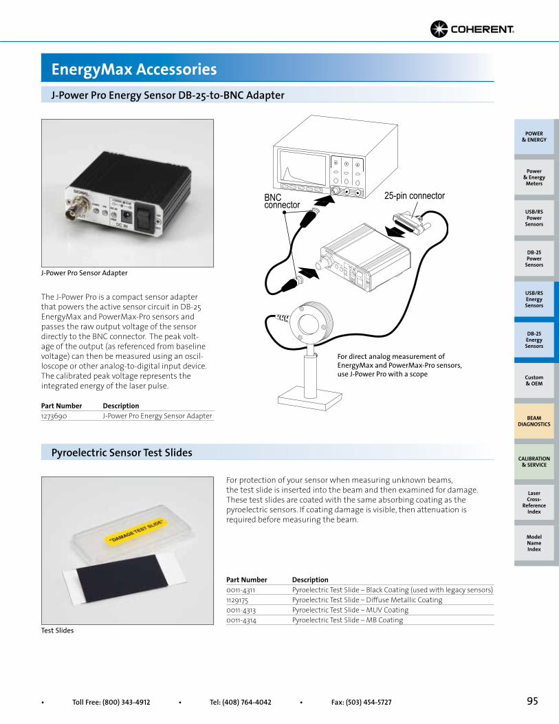
95• Toll Free: (800) 343-4912 • Tel: (408) 764-4042 • Fax: (503) 454-5727
The J-Power Pro is a compact sensor adapter that powers the active sensor circuit in DB-25 EnergyMax and PowerMax-Pro sensors and passes the raw output voltage of the sensor directly to the BNC connector. The peak volt-age of the output (as referenced from baseline voltage) can then be measured using an oscil-loscope or other analog-to-digital input device. The calibrated peak voltage represents the integrated energy of the laser pulse.
. . . . . . . . . . . . . . .
25-pin connector BNC connector
J-Power Pro Energy Sensor DB-25-to-BNC Adapter
EnergyMax Accessories
Part Number Description0011-4311 Pyroelectric Test Slide – Black Coating (used with legacy sensors)1129175 Pyroelectric Test Slide – Diffuse Metallic Coating0011-4313 Pyroelectric Test Slide – MUV Coating0011-4314 Pyroelectric Test Slide – MB Coating
Part Number Description1273690 J-Power Pro Energy Sensor Adapter
Pyroelectric Sensor Test Slides
For protection of your sensor when measuring unknown beams, the test slide is inserted into the beam and then examined for damage. These test slides are coated with the same absorbing coating as the pyroelectric sensors. If coating damage is visible, then attenuation is required before measuring the beam.
J-Power Pro Sensor Adapter
For direct analog measurement of EnergyMax and PowerMax-Pro sensors, use J-Power Pro with a scope
Test Slides
POWER & ENERGY
Custom & OEM
BEAM DIAGNOSTICS
CALIBRATION & SERVICE
Power & Energy
Meters
Laser Cross-
Reference Index
Model Name Index
DB-25Energy Sensors
USB/RSEnergy Sensors
DB-25Power
Sensors
USB/RSPower
Sensors
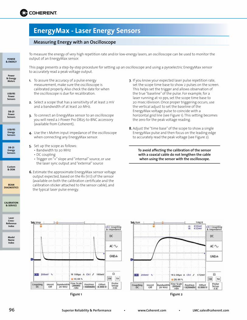
96 Superior Reliability & Performance • www.Coherent.com • [email protected]
To measure the energy of very high repetition rate and/or low-energy lasers, an oscilloscope can be used to monitor the output of an EnergyMax sensor.
This page presents a step-by-step procedure for setting up an oscilloscope and using a pyroelectric EnergyMax sensor to accurately read a peak voltage output.
Figure 1 Figure 2
Measuring Energy with an Oscilloscope
EnergyMax - Laser Energy Sensors
7. If you know your expected laser pulse repetition rate, set the scope time base to show 2 pulses on the screen. This helps set the trigger and allows observation of the true “baseline” of the pulse. For example, for a laser running at 10 pps, set the scope time base to 20 msec/division. Once proper triggering occurs, use the vertical adjust to set the baseline of the EnergyMax voltage pulse to coincide with a horizontal grid line (see Figure 1). This setting becomes the zero for the peak voltage reading.
8. Adjust the “time base” of the scope to show a single EnergyMax pulse and then focus on the leading edge to accurately read the peak voltage (see Figure 2).
To avoid affecting the calibration of the sensor with a coaxial cable do not lengthen the cablewhen using the sensor with the oscilloscope.
1. To assure the accuracy of a pulse energy measurement, make sure the oscilloscope is calibrated properly. Also check the date for when the oscilloscope is due for recalibration.
2. Select a scope that has a sensitivity of at least 2 mV and a bandwidth of at least 20 MHz.
3. To connect an EnergyMax sensor to an oscilloscope you will need a J-Power Pro DB25-to-BNC accessory (available from Coherent).
4. Use the 1 Mohm input impedance of the oscilloscope when connecting any EnergyMax sensor.
5. Set up the scope as follows: • Bandwidth to 20 MHz • DC coupling • Trigger on “+” slope and “internal” source, or use the laser sync output and “external” source
6. Estimate the approximate EnergyMax sensor voltage output expected, based on the Rv (V/J) of the sensor (available on both the calibration certificate and the calibration sticker attached to the sensor cable), and the typical laser pulse energy.
POWER & ENERGY
Custom & OEM
BEAM DIAGNOSTICS
CALIBRATION & SERVICE
Power & Energy
Meters
Laser Cross-
Reference Index
Model Name Index
DB-25Energy Sensors
USB/RSEnergy Sensors
DB-25Power
Sensors
USB/RSPower
Sensors
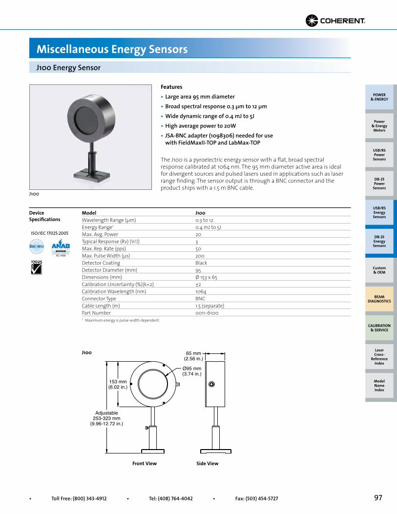
97• Toll Free: (800) 343-4912 • Tel: (408) 764-4042 • Fax: (503) 454-5727
153 mm(6.02 in.)
65 mm(2.56 in.)
Ø95 mm(3.74 in.)
Adjustable253-323 mm
(9.96-12.72 in.)
Front View
Model J100Wavelength Range (µm) 0.3 to 12Energy Range1 0.4 mJ to 5JMax. Avg. Power 20Typical Response (Rv) (V/J) 3Max. Rep. Rate (pps) 50 Max. Pulse Width (µs) 200Detector Coating BlackDetector Diameter (mm) 95Dimensions (mm) Ø 153 x 65Calibration Uncertainty (%)(k=2) ±2Calibration Wavelength (nm) 1064Connector Type BNCCable Length (m) 1.5 (separate)Part Number 0011-6100
Features• Large area 95 mm diameter• Broad spectral response 0.3 µm to 12 µm• Wide dynamic range of 0.4 mJ to 5J• High average power to 20W• JSA-BNC adapter (1098306) needed for use with FieldMaxII-TOP and LabMax-TOP
Miscellaneous Energy Sensors
The J100 is a pyroelectric energy sensor with a flat, broad spectral response calibrated at 1064 nm. The 95 mm diameter active area is ideal for divergent sources and pulsed lasers used in applications such as laser range finding. The sensor output is through a BNC connector and the product ships with a 1.5 m BNC cable.
J100 Energy Sensor
J100
Device Specifications
J100
Side View
1 Maximum energy is pulse-width dependent.
POWER & ENERGY
Custom & OEM
BEAM DIAGNOSTICS
CALIBRATION & SERVICE
Power & Energy
Meters
Laser Cross-
Reference Index
Model Name Index
DB-25Energy Sensors
USB/RSEnergy Sensors
DB-25Power
Sensors
USB/RSPower
Sensors
ISO/IEC 17025:2005
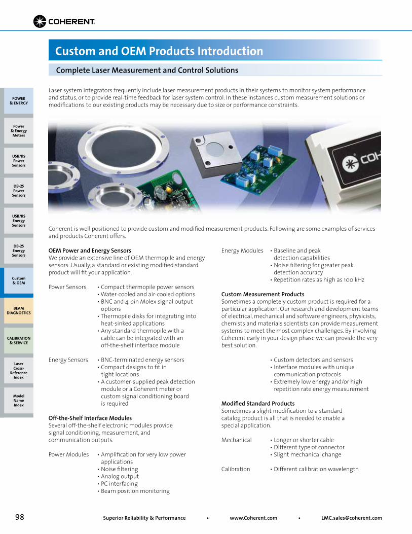
98 Superior Reliability & Performance • www.Coherent.com • [email protected]
Laser system integrators frequently include laser measurement products in their systems to monitor system performance and status, or to provide real-time feedback for laser system control. In these instances custom measurement solutions or modifications to our existing products may be necessary due to size or performance constraints.
Coherent is well positioned to provide custom and modified measurement products. Following are some examples of services and products Coherent offers.
OEM Power and Energy SensorsWe provide an extensive line of OEM thermopile and energy sensors. Usually, a standard or existing modified standard product will fit your application.
Power Sensors • Compact thermopile power sensors • Water-cooled and air-cooled options • BNC and 4-pin Molex signal output options • Thermopile disks for integrating into heat-sinked applications • Any standard thermopile with a cable can be integrated with an off-the-shelf interface module
Energy Sensors • BNC-terminated energy sensors • Compact designs to fit in tight locations • A customer-supplied peak detection module or a Coherent meter or custom signal conditioning board is required
Off-the-Shelf Interface ModulesSeveral off-the-shelf electronic modules provide signal conditioning, measurement, and communication outputs.
Power Modules • Amplification for very low power applications • Noise filtering • Analog output • PC interfacing • Beam position monitoring
Energy Modules • Baseline and peak detection capabilities • Noise filtering for greater peak detection accuracy • Repetition rates as high as 100 kHz
Custom Measurement ProductsSometimes a completely custom product is required for a particular application. Our research and development teams of electrical, mechanical and software engineers, physicists, chemists and materials scientists can provide measurement systems to meet the most complex challenges. By involving Coherent early in your design phase we can provide the very best solution.
• Custom detectors and sensors • Interface modules with unique communication protocols • Extremely low energy and/or high repetition rate energy measurement
Modified Standard ProductsSometimes a slight modification to a standard catalog product is all that is needed to enable a special application.
Mechanical • Longer or shorter cable • Different type of connector • Slight mechanical change
Calibration • Different calibration wavelength
Complete Laser Measurement and Control Solutions
Custom and OEM Products Introduction
POWER & ENERGY
Custom & OEM
BEAM DIAGNOSTICS
CALIBRATION & SERVICE
Power & Energy
Meters
Laser Cross-
Reference Index
Model Name Index
DB-25Energy Sensors
USB/RSEnergy Sensors
DB-25Power
Sensors
USB/RSPower
Sensors
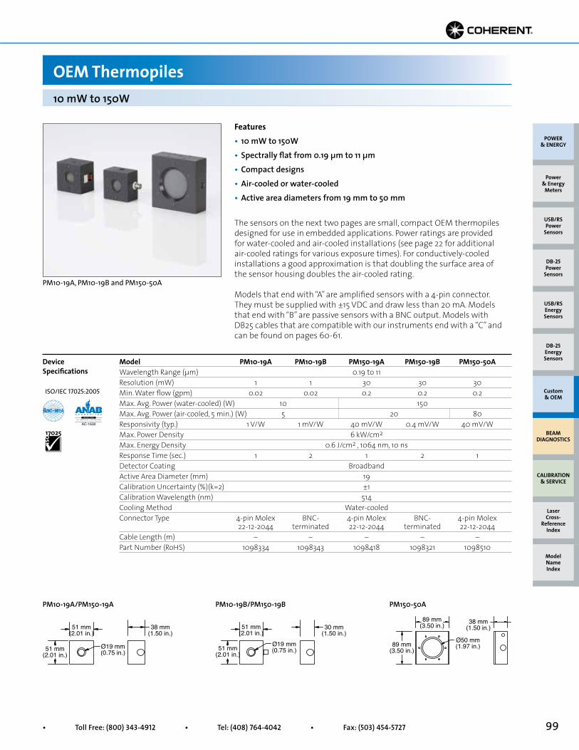
99• Toll Free: (800) 343-4912 • Tel: (408) 764-4042 • Fax: (503) 454-5727
51 mm(2.01 in.)
38 mm(1.50 in.)
51 mm(2.01 in.)
Ø19 mm(0.75 in.)
51 mm(2.01 in.)
30 mm(1.50 in.)
51 mm(2.01 in.)
Ø19 mm(0.75 in.)
89 mm(3.50 in.) 38 mm
(1.50 in.)
89 mm(3.50 in.)
Ø50 mm(1.97 in.)
The sensors on the next two pages are small, compact OEM thermopiles designed for use in embedded applications. Power ratings are provided for water-cooled and air-cooled installations (see page 22 for additional air-cooled ratings for various exposure times). For conductively-cooled installations a good approximation is that doubling the surface area of the sensor housing doubles the air-cooled rating.
Models that end with “A” are amplified sensors with a 4-pin connector. They must be supplied with ±15 VDC and draw less than 20 mA. Models that end with “B” are passive sensors with a BNC output. Models with DB25 cables that are compatible with our instruments end with a “C” and can be found on pages 60-61.
10 mW to 150W
OEM Thermopiles
Features• 10 mW to 150W• Spectrally flat from 0.19 µm to 11 µm• Compact designs• Air-cooled or water-cooled• Active area diameters from 19 mm to 50 mm
PM10-19A, PM10-19B and PM150-50A
Model PM10-19A PM10-19B PM150-19A PM150-19B PM150-50AWavelength Range (µm) 0.19 to 11Resolution (mW) 1 1 30 30 30Min. Water flow (gpm) 0.02 0.02 0.2 0.2 0.2Max. Avg. Power (water-cooled) (W) 10 150Max. Avg. Power (air-cooled, 5 min.) (W) 5 20 80Responsivity (typ.) 1 V/W 1 mV/W 40 mV/W 0.4 mV/W 40 mV/WMax. Power Density 6 kW/cm2
Max. Energy Density 0.6 J/cm2 , 1064 nm, 10 nsResponse Time (sec.) 1 2 1 2 1Detector Coating BroadbandActive Area Diameter (mm) 19Calibration Uncertainty (%)(k=2) ±1Calibration Wavelength (nm) 514Cooling Method Water-cooledConnector Type 4-pin Molex BNC- 4-pin Molex BNC- 4-pin Molex 22-12-2044 terminated 22-12-2044 terminated 22-12-2044Cable Length (m) – – – – –Part Number (RoHS) 1098334 1098343 1098418 1098321 1098510
Device Specifications
PM10-19A/PM150-19A
PM10-19B/PM150-19B
PM150-50A
POWER & ENERGY
Custom & OEM
BEAM DIAGNOSTICS
CALIBRATION & SERVICE
Power & Energy
Meters
Laser Cross-
Reference Index
Model Name Index
DB-25Energy Sensors
USB/RSEnergy Sensors
DB-25Power
Sensors
USB/RSPower
Sensors
ISO/IEC 17025:2005
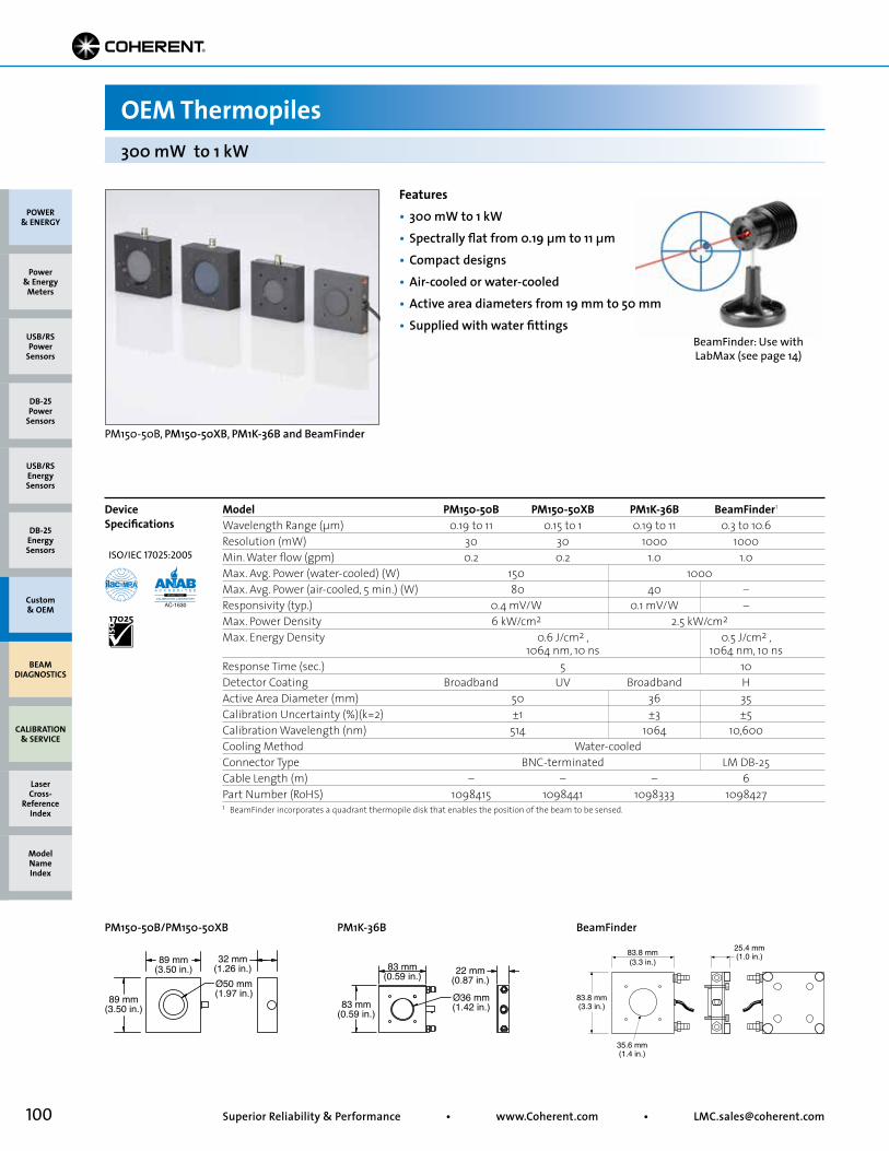
100 Superior Reliability & Performance • www.Coherent.com • [email protected]
83 mm(0.59 in.)
83 mm(0.59 in.)
Ø36 mm(1.42 in.)
22 mm(0.87 in.)
89 mm(3.50 in.)
89 mm(3.50 in.)
Ø50 mm(1.97 in.)
32 mm(1.26 in.)
25.4 mm(1.0 in.)83.8 mm
(3.3 in.)
83.8 mm(3.3 in.)
35.6 mm(1.4 in.)
BeamFinder: Use with LabMax (see page 14)
300 mW to 1 kW
OEM Thermopiles
Features• 300 mW to 1 kW• Spectrally flat from 0.19 µm to 11 µm• Compact designs• Air-cooled or water-cooled• Active area diameters from 19 mm to 50 mm• Supplied with water fittings
PM150-50B, PM150-50XB, PM1K-36B and BeamFinder
PM150-50B/PM150-50XB
PM1K-36B
BeamFinder
POWER & ENERGY
Custom & OEM
BEAM DIAGNOSTICS
CALIBRATION & SERVICE
Power & Energy
Meters
Laser Cross-
Reference Index
Model Name Index
DB-25Energy Sensors
USB/RSEnergy Sensors
DB-25Power
Sensors
USB/RSPower
Sensors
Model PM150-50B PM150-50XB PM1K-36B BeamFinder1
Wavelength Range (µm) 0.19 to 11 0.15 to 1 0.19 to 11 0.3 to 10.6Resolution (mW) 30 30 1000 1000Min. Water flow (gpm) 0.2 0.2 1.0 1.0Max. Avg. Power (water-cooled) (W) 150 1000Max. Avg. Power (air-cooled, 5 min.) (W) 80 40 –Responsivity (typ.) 0.4 mV/W 0.1 mV/W –Max. Power Density 6 kW/cm2 2.5 kW/cm2
Max. Energy Density 0.6 J/cm2 , 0.5 J/cm2 , 1064 nm, 10 ns 1064 nm, 10 nsResponse Time (sec.) 5 10Detector Coating Broadband UV Broadband HActive Area Diameter (mm) 50 36 35Calibration Uncertainty (%)(k=2) ±1 ±3 ±5Calibration Wavelength (nm) 514 1064 10,600Cooling Method Water-cooledConnector Type BNC-terminated LM DB-25Cable Length (m) – – – 6Part Number (RoHS) 1098415 1098441 1098333 1098427
Device Specifications
1 BeamFinder incorporates a quadrant thermopile disk that enables the position of the beam to be sensed.
ISO/IEC 17025:2005
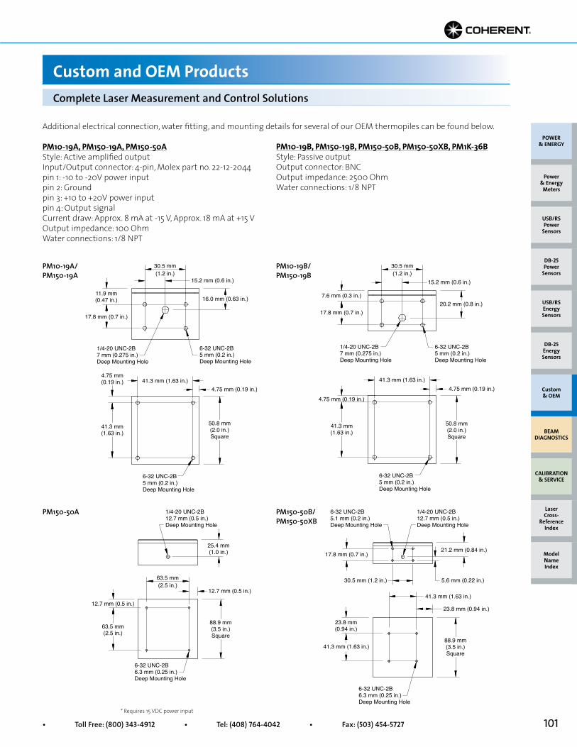
101• Toll Free: (800) 343-4912 • Tel: (408) 764-4042 • Fax: (503) 454-5727
1/4-20 UNC-2B7 mm (0.275 in.)Deep Mounting Hole
6-32 UNC-2B5 mm (0.2 in.)Deep Mounting Hole
6-32 UNC-2B5 mm (0.2 in.)Deep Mounting Hole
50.8 mm(2.0 in.)Square
16.0 mm (0.63 in.)
15.2 mm (0.6 in.)
11.9 mm(0.47 in.)
17.8 mm (0.7 in.)
41.3 mm (1.63 in.)
30.5 mm(1.2 in.)
41.3 mm(1.63 in.)
4.75 mm (0.19 in.)
4.75 mm(0.19 in.)
6-32 UNC-2B5 mm (0.2 in.)Deep Mounting Hole
6-32 UNC-2B5 mm (0.2 in.)Deep Mounting Hole
1/4-20 UNC-2B7 mm (0.275 in.)Deep Mounting Hole
50.8 mm(2.0 in.)Square
20.2 mm (0.8 in.)
15.2 mm (0.6 in.)
17.8 mm (0.7 in.)
7.6 mm (0.3 in.)
30.5 mm(1.2 in.)
41.3 mm(1.63 in.)
41.3 mm (1.63 in.)
4.75 mm (0.19 in.)
4.75 mm (0.19 in.)
1/4-20 UNC-2B12.7 mm (0.5 in.)Deep Mounting Hole
6-32 UNC-2B6.3 mm (0.25 in.)Deep Mounting Hole
25.4 mm(1.0 in.)
63.5 mm(2.5 in.)
88.9 mm(3.5 in.)Square
63.5 mm(2.5 in.)
12.7 mm (0.5 in.)
12.7 mm (0.5 in.)
1/4-20 UNC-2B12.7 mm (0.5 in.)Deep Mounting Hole
6-32 UNC-2B6.3 mm (0.25 in.)Deep Mounting Hole
6-32 UNC-2B5.1 mm (0.2 in.)Deep Mounting Hole
88.9 mm(3.5 in.)Square
21.2 mm (0.84 in.)17.8 mm (0.7 in.)
30.5 mm (1.2 in.) 5.6 mm (0.22 in.)
41.3 mm (1.63 in.)
23.8 mm (0.94 in.)
23.8 mm(0.94 in.)
41.3 mm (1.63 in.)
Additional electrical connection, water fitting, and mounting details for several of our OEM thermopiles can be found below.
PM10-19A, PM150-19A, PM150-50AStyle: Active amplified outputInput/Output connector: 4-pin, Molex part no. 22-12-2044pin 1: -10 to -20V power input pin 2: Groundpin 3: +10 to +20V power inputpin 4: Output signalCurrent draw: Approx. 8 mA at -15 V, Approx. 18 mA at +15 VOutput impedance: 100 OhmWater connections: 1/8 NPT
* Requires 15 VDC power input
PM10-19A/ PM150-19A
PM10-19B/ PM150-19B
PM150-50A PM150-50B/ PM150-50XB
PM10-19B, PM150-19B, PM150-50B, PM150-50XB, PM1K-36BStyle: Passive outputOutput connector: BNC Output impedance: 2500 OhmWater connections: 1/8 NPT
Complete Laser Measurement and Control Solutions
Custom and OEM Products
POWER & ENERGY
Custom & OEM
BEAM DIAGNOSTICS
CALIBRATION & SERVICE
Power & Energy
Meters
Laser Cross-
Reference Index
Model Name Index
DB-25Energy Sensors
USB/RSEnergy Sensors
DB-25Power
Sensors
USB/RSPower
Sensors
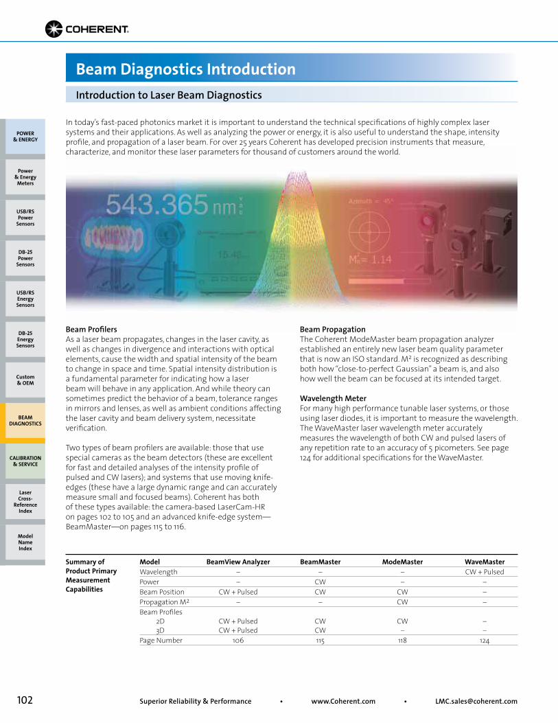
102 Superior Reliability & Performance • www.Coherent.com • [email protected]
In today’s fast-paced photonics market it is important to understand the technical specifications of highly complex laser systems and their applications. As well as analyzing the power or energy, it is also useful to understand the shape, intensity profile, and propagation of a laser beam. For over 25 years Coherent has developed precision instruments that measure, characterize, and monitor these laser parameters for thousand of customers around the world.
Beam ProfilersAs a laser beam propagates, changes in the laser cavity, aswell as changes in divergence and interactions with opticalelements, cause the width and spatial intensity of the beamto change in space and time. Spatial intensity distribution isa fundamental parameter for indicating how a laser beam will behave in any application. And while theory can sometimes predict the behavior of a beam, tolerance ranges in mirrors and lenses, as well as ambient conditions affecting the laser cavity and beam delivery system, necessitate verification.
Two types of beam profilers are available: those that usespecial cameras as the beam detectors (these are excellentfor fast and detailed analyses of the intensity profile ofpulsed and CW lasers); and systems that use moving knife-edges (these have a large dynamic range and can accuratelymeasure small and focused beams). Coherent has bothof these types available: the camera-based LaserCam-HR on pages 102 to 105 and an advanced knife-edge system—BeamMaster—on pages 115 to 116.
Beam PropagationThe Coherent ModeMaster beam propagation analyzerestablished an entirely new laser beam quality parameterthat is now an ISO standard. M2 is recognized as describingboth how “close-to-perfect Gaussian” a beam is, and alsohow well the beam can be focused at its intended target.
Wavelength MeterFor many high performance tunable laser systems, or those using laser diodes, it is important to measure the wavelength. The WaveMaster laser wavelength meter accurately measures the wavelength of both CW and pulsed lasers of any repetition rate to an accuracy of 5 picometers. See page 124 for additional specifications for the WaveMaster.
Introduction to Laser Beam Diagnostics
Beam Diagnostics Introduction
Model BeamView Analyzer BeamMaster ModeMaster WaveMasterWavelength – – – CW + PulsedPower – CW – –Beam Position CW + Pulsed CW CW –Propagation M2 – – CW –Beam Profiles 2D CW + Pulsed CW CW – 3D CW + Pulsed CW – –Page Number 106 115 118 124
Summary of Product Primary Measurement Capabilities
POWER & ENERGY
Custom & OEM
BEAM DIAGNOSTICS
CALIBRATION & SERVICE
Power & Energy
Meters
Laser Cross-
Reference Index
Model Name Index
DB-25Energy Sensors
USB/RSEnergy Sensors
DB-25Power
Sensors
USB/RSPower
Sensors
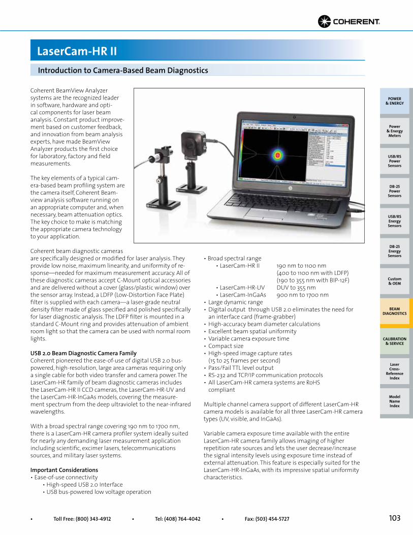
103• Toll Free: (800) 343-4912 • Tel: (408) 764-4042 • Fax: (503) 454-5727
Introduction to Camera-Based Beam Diagnostics
LaserCam-HR II
Coherent BeamView Analyzer systems are the recognized leader in software, hardware and opti-cal components for laser beam analysis. Constant product improve-ment based on customer feedback, and innovation from beam analysis experts, have made BeamView Analyzer products the first choice for laboratory, factory and field measurements.
The key elements of a typical cam-era-based beam profiling system are the camera itself, Coherent Beam-view analysis software running on an appropriate computer and, when necessary, beam attenuation optics. The key choice to make is matching the appropriate camera technology to your application.
Coherent beam diagnostic cameras are specifically designed or modified for laser analysis. They provide low noise, maximum linearity, and uniformity of re-sponse—needed for maximum measurement accuracy. All of these diagnostic cameras accept C-Mount optical accessories and are delivered without a cover (glass/plastic window) over the sensor array. Instead, a LDFP (Low-Distortion Face Plate) filter is supplied with each camera—a laser-grade neutral density filter made of glass specified and polished specifically for laser diagnostic analysis. The LDFP filter is mounted in a standard C-Mount ring and provides attenuation of ambient room light so that the camera can be used with normal room lights.
USB 2.0 Beam Diagnostic Camera Family Coherent pioneered the ease-of-use of digital USB 2.0 bus-powered, high-resolution, large area cameras requiring only a single cable for both video transfer and camera power. The LaserCam-HR family of beam diagnostic cameras includes the LaserCam-HR II CCD cameras, the LaserCam-HR-UV and the LaserCam-HR-InGaAs models, covering the measure-ment spectrum from the deep ultraviolet to the near-infrared wavelengths.
With a broad spectral range covering 190 nm to 1700 nm, there is a LaserCam-HR camera profiler system ideally suited for nearly any demanding laser measurement application including scientific, excimer lasers, telecommunications sources, and military laser systems.
Important Considerations • Ease-of-use connectivity • High-speed USB 2.0 Interface • USB bus-powered low voltage operation
• Broad spectral range • LaserCam-HR II 190 nm to 1100 nm (400 to 1100 nm with LDFP) (190 to 355 nm with BIP-12F) • LaserCam-HR-UV DUV to 355 nm • LaserCam-InGaAs 900 nm to 1700 nm• Large dynamic range• Digital output through USB 2.0 eliminates the need for an interface card (frame-grabber)• High-accuracy beam diameter calculations• Excellent beam spatial uniformity• Variable camera exposure time• Compact size• High-speed image capture rates (15 to 25 frames per second)• Pass/Fail TTL level output• RS-232 and TCP/IP communication protocols• All LaserCam-HR camera systems are RoHS compliant
Multiple channel camera support of different LaserCam-HR camera models is available for all three LaserCam-HR camera types (UV, visible, and InGaAs).
Variable camera exposure time available with the entire LaserCam-HR camera family allows imaging of higher repetition rate sources and lets the user decrease/increase the signal intensity levels using exposure time instead of external attenuation. This feature is especially suited for the LaserCam-HR-InGaAs, with its impressive spatial uniformity characteristics.
POWER & ENERGY
Custom & OEM
BEAM DIAGNOSTICS
CALIBRATION & SERVICE
Power & Energy
Meters
Laser Cross-
Reference Index
Model Name Index
DB-25Energy Sensors
USB/RSEnergy Sensors
DB-25Power
Sensors
USB/RSPower
Sensors
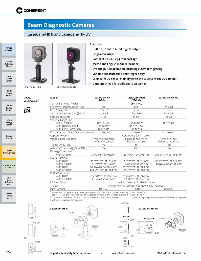
104 Superior Reliability & Performance • www.Coherent.com • [email protected]
Protective Cap
LDFP Adaptor
Rotational Mount(Metric and English
included)
3” Post and StandIncluded
6 mm(0.25 in.)
79 mm(3.12 in.)
68 mm(2.68 in.)
68 mm(2.68 in.)
10 mm(0.40 in.)
1/4-20 UNC
15 mm(0.59 in.)
43 mm(1.70 in.)
28 mm(1.11 in.)
Model LaserCam-HR II LaserCam-HR II LaserCam-HR-UV 1/2-inch 2/3-inchSensor Elements (pixels) 1280 x 1024 Effective Pixel Resolution (µm) n/a n/a 20 x 20Pixel Size (µm) 4.6 x 4.6 6.5 x 6.5 n/aSensor Active Area (mm)(H x V) 5.9 x 4.8 8.3 x 6.6 8.5 x 6.8Camera Bit Depth 12-bit 14-bit 10-bitSpectral Range (nm) without LDFP 190 to 11001 190 to 11001 190 to 355 with LDFP included 400 to 1100 400 to 1100 with BIP-12F accessory 190 to 355 190 to 355Recommended Beam Diameters (mm) 0.15 to 4.02 0.2 to 6.02 0.5 to 6.0Capture Modes Continuous (CW), pulsedVariable Exposure Time 1 msec to 500 msec, 1 msec to 500 msec, 1 msec to 1 sec, default at 5 msec default at 5 msec default at 10 msecTrigger Delay (µs) 75 20 160Maximum Pulse Trigger in Rate3 (Hz) 200 200 100Damage Threshold without LDFP 32 mJ/cm2 at 1064 nm 32 mJ/cm2 at 1064 nm 200 µJ/cm2 at 1064 nm4
CW Saturation with LDFP 13 mW/cm2 at 633 nm 5 mW/cm2 at 633 nm 90 mW/cm2 at 248 nm5
without LDFP 5 µW/cm2 at 633 nm 2 µW/cm2 at 633 nm 90 µW/cm2 at 248 nm4
with LDFP 70 mW/cm2 at 1064 nm 25 mW/cm2 at 1064 nm without LDFP 340 µW/cm2 at 1064 nm 125 µW/cm2 at 1064 nmPulsed Saturation with LDFP 0.4 mJ/cm2 at 1064 nm 0.15 mJ/cm2 at 1064 nm without LDFP 2 µJ/cm2 at 1064 nm 0.7 µJ/cm2 at 1064 nmUSB 2.0 Cable 10 ft. standard A/B cable includedTrigger Connector BNC receptacle (trigger cable included)Part Number 1282868 1282870 1149004
Features• USB 2.0, 10-bit to 14-bit digital output• Large area arrays• Compact 68 x 68 x 34 mm package• Metric and English mounts included• CW and pulsed operation including external triggering• Variable exposure time and trigger delay• Long-term UV sensor stability (with the LaserCam-HR-UV camera)• C-mount thread for additional accessories
LaserCam-HR II LaserCam-HR-UV
Device Specifications
LaserCam-HR II and LaserCam-HR-UV
Beam Diagnostic Cameras
POWER & ENERGY
Custom & OEM
BEAM DIAGNOSTICS
CALIBRATION & SERVICE
Power & Energy
Meters
Laser Cross-
Reference Index
Model Name Index
DB-25Energy Sensors
USB/RSEnergy Sensors
DB-25Power
Sensors
USB/RSPower
Sensors
27.2 mm(1.07 in.)
Image Plane LDFP Adapter
Protective CapRotational Mount
(Metric and Englishincluded)
18.7 mm(0.74 in.)
74.3 mm(2.93 in.)
9.9 mm(0.39 in.)
1/4-20 UNC
41.8 mm(1.65 in.)
68.1 mm(2.68 in.)
Ø11.2 mm(0.44 in.)
68.1 mm(2.68 in.)
79.3 mm(3.12 in.)
LaserCam-HR II LaserCam-HR-UV
1 There is a risk of degradation in the range of 190 nm to 300 nm due to DUV exposure. The optional BIP-12F (page 114) UV-to-visible fluorescence converter can be used to prevent drift.2 It is possible to measure beams <0.2 mm in diameter, but resolution is reduced.3 Without averaging adjacent pulses.
4 Without LDFP-UV. 5 With LDFP-UV.** C24 Quick Ship program: eligible for next business day shipment.
**
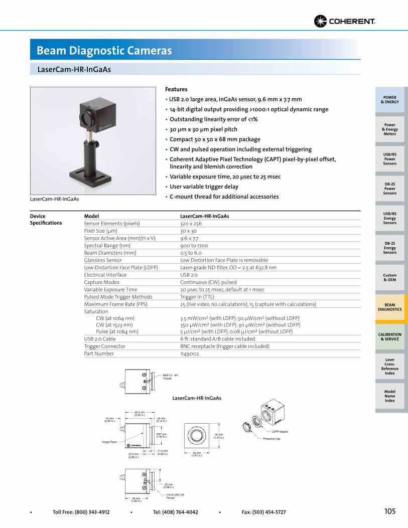
105• Toll Free: (800) 343-4912 • Tel: (408) 764-4042 • Fax: (503) 454-5727
M6X1.0 - 6HThread
Image Plane
1/4-20 UNC-2BThread
LDFP Adapter
Protective Cap
59.3 mm(2.34 in.)
10 mm(0.39 in.)
54 mm(2.14 in.)
25 mm(0.98 in.)
46 mm(1.82 in.)
Ø37 mm(1.44 in.)
17.5 mm(0.69 in.)22.5 mm
(0.88 in.)
50 mm(1.97 in.)
50 mm(1.97 in.)
Features• USB 2.0 large area, InGaAs sensor, 9.6 mm x 7.7 mm• 14-bit digital output providing >1000:1 optical dynamic range• Outstanding linearity error of <1%• 30 µm x 30 µm pixel pitch• Compact 50 x 50 x 68 mm package• CW and pulsed operation including external triggering• Coherent Adaptive Pixel Technology (CAPT) pixel-by-pixel offset, linearity and blemish correction• Variable exposure time, 20 µsec to 25 msec• User variable trigger delay• C-mount thread for additional accessories
Model LaserCam-HR-InGaAsSensor Elements (pixels) 320 x 256Pixel Size (µm) 30 x 30Sensor Active Area (mm)(H x V) 9.6 x 7.7Spectral Range (nm) 900 to 1700Beam Diameters (mm) 0.5 to 6.0Glassless Sensor Low Distortion Face Plate is removableLow-Distortion Face Plate (LDFP) Laser-grade ND filter, OD = 2.5 at 632.8 nmElectrical Interface USB 2.0Capture Modes Continuous (CW), pulsedVariable Exposure Time 20 µsec to 25 msec, default at 1 msecPulsed Mode Trigger Methods Trigger In (TTL)Maximum Frame Rate (FPS) 25 (live video, no calculations), 15 (capture with calculations)Saturation CW (at 1064 nm) 3.5 mW/cm2 (with LDFP), 50 µW/cm2 (without LDFP) CW (at 1523 nm) 350 µW/cm2 (with LDFP), 30 µW/cm2 (without LDFP) Pulse (at 1064 nm) 5 µJ/cm2 (with LDFP), 0.08 µJ/cm2 (without LDFP)USB 2.0 Cable 6 ft. standard A/B cable includedTrigger Connector BNC receptacle (trigger cable included)Part Number 1149002
Device Specifications
LaserCam-HR-InGaAs
Beam Diagnostic Cameras
LaserCam-HR-InGaAs
LaserCam-HR-InGaAs
POWER & ENERGY
Custom & OEM
BEAM DIAGNOSTICS
CALIBRATION & SERVICE
Power & Energy
Meters
Laser Cross-
Reference Index
Model Name Index
DB-25Energy Sensors
USB/RSEnergy Sensors
DB-25Power
Sensors
USB/RSPower
Sensors
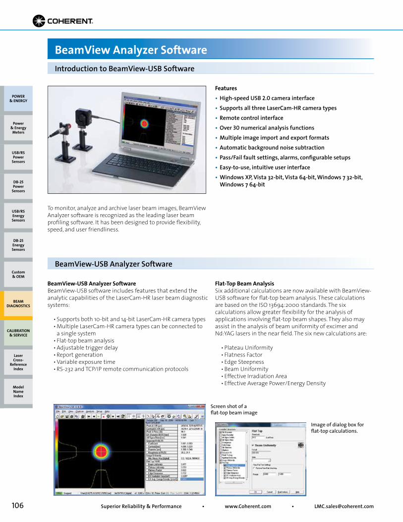
106 Superior Reliability & Performance • www.Coherent.com • [email protected]
Features• High-speed USB 2.0 camera interface• Supports all three LaserCam-HR camera types• Remote control interface• Over 30 numerical analysis functions• Multiple image import and export formats• Automatic background noise subtraction• Pass/Fail fault settings, alarms, configurable setups• Easy-to-use, intuitive user interface • Windows XP, Vista 32-bit, Vista 64-bit, Windows 7 32-bit, Windows 7 64-bit
To monitor, analyze and archive laser beam images, BeamView Analyzer software is recognized as the leading laser beam profiling software. It has been designed to provide flexibility, speed, and user friendliness.
Screen shot of a flat-top beam image
Image of dialog box for flat-top calculations.
Introduction to BeamView-USB Software
BeamView Analyzer Software
BeamView-USB Analyzer Software
BeamView-USB Analyzer SoftwareBeamView-USB software includes features that extend the analytic capabilities of the LaserCam-HR laser beam diagnostic systems:
• Supports both 10-bit and 14-bit LaserCam-HR camera types • Multiple LaserCam-HR camera types can be connected to a single system • Flat-top beam analysis • Adjustable trigger delay • Report generation • Variable exposure time • RS-232 and TCP/IP remote communication protocols
Flat-Top Beam AnalysisSix additional calculations are now available with BeamView-USB software for flat-top beam analysis. These calculations are based on the ISO 13694:2000 standards. The six calculations allow greater flexibility for the analysis of applications involving flat-top beam shapes. They also may assist in the analysis of beam uniformity of excimer and Nd:YAG lasers in the near field. The six new calculations are:
• Plateau Uniformity • Flatness Factor • Edge Steepness • Beam Uniformity • Effective Irradiation Area • Effective Average Power/Energy Density
POWER & ENERGY
Custom & OEM
BEAM DIAGNOSTICS
CALIBRATION & SERVICE
Power & Energy
Meters
Laser Cross-
Reference Index
Model Name Index
DB-25Energy Sensors
USB/RSEnergy Sensors
DB-25Power
Sensors
USB/RSPower
Sensors
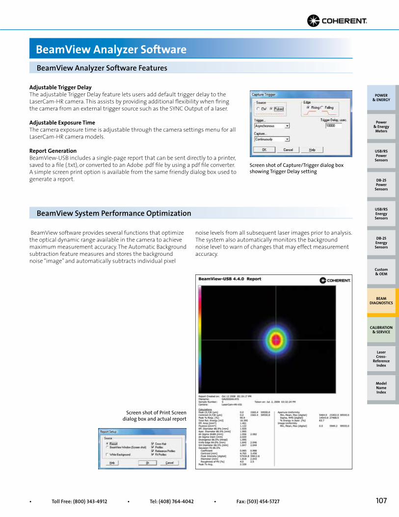
107• Toll Free: (800) 343-4912 • Tel: (408) 764-4042 • Fax: (503) 454-5727
Adjustable Trigger DelayThe adjustable Trigger Delay feature lets users add default trigger delay to the LaserCam-HR camera. This assists by providing additional flexibility when firing the camera from an external trigger source such as the SYNC Output of a laser.
Adjustable Exposure TimeThe camera exposure time is adjustable through the camera settings menu for all LaserCam-HR camera models.
Report GenerationBeamView-USB includes a single-page report that can be sent directly to a printer, saved to a file (.txt), or converted to an Adobe .pdf file by using a pdf file converter. A simple screen print option is available from the same friendly dialog box used to generate a report.
Screen shot of Capture/Trigger dialog box showing Trigger Delay setting
BeamView Analyzer Software Features
BeamView Analyzer Software
BeamView software provides several functions that optimize the optical dynamic range available in the camera to achieve maximum measurement accuracy. The Automatic Background subtraction feature measures and stores the background noise “image” and automatically subtracts individual pixel
Screen shot of Print Screen dialog box and actual report
BeamView System Performance Optimization
noise levels from all subsequent laser images prior to analysis. The system also automatically monitors the background noise level to warn of changes that may effect measurement accuracy.
POWER & ENERGY
Custom & OEM
BEAM DIAGNOSTICS
CALIBRATION & SERVICE
Power & Energy
Meters
Laser Cross-
Reference Index
Model Name Index
DB-25Energy Sensors
USB/RSEnergy Sensors
DB-25Power
Sensors
USB/RSPower
Sensors

108 Superior Reliability & Performance • www.Coherent.com • [email protected]
Real-Time Laser Monitoring and AlignmentThe Live Video mode provides a continuously updated image of the beam (~20 Hz to 25 Hz, depending on the speed of the processor) displayed in shades of gray or pseudo-color. This mode is ideal for monitoring the laser and observing changes in the form and structure of the beam as it is adjusted. It also allows for real-time tuning to achieve optimum beam profile quality and laser-cavity alignment. While operating in this mode, no beam or statistical data are displayed, but if Run is activated, the image is stored and can be analyzed later.
BeamView Analyzer Software Additional Features • More than 25 different numerical analysis functions• Several different profile views• Import and export of results data and profile data• Pass/Fail settings and user-selectable fault actions
The Live Video mode
BeamView Analyzer display with 3D image and ISO-compatible results
2D and 3D Intensity Plots The Run command switches the BeamView Analyzer from the Stop or Live Video mode to continuous operation, which provides capture, analysis and display of beam image data. The view area of the computer monitor provides a choice of 2D or 3D images. The 2D contour maps and the 3D isometric plots display laser beam intensity profiles in a choice of color and gray-scale styles (fixed and autoscaling to a peak) and sizes
(continuous zoom and pan control). The 2D maps can be shown with or without profiles (and Gaussian fit), reference position, variable aperture and rotatable crosshairs (with auto peak and auto centroid location). The 3D isometric plots can be displayed with transparent, hidden or solid wires, and can be rotated and viewed from different tilt angles.
Choice of 3D and 2D images
BeamView Analyzer Software Features
BeamView Analyzer Software
POWER & ENERGY
Custom & OEM
BEAM DIAGNOSTICS
CALIBRATION & SERVICE
Power & Energy
Meters
Laser Cross-
Reference Index
Model Name Index
DB-25Energy Sensors
USB/RSEnergy Sensors
DB-25Power
Sensors
USB/RSPower
Sensors
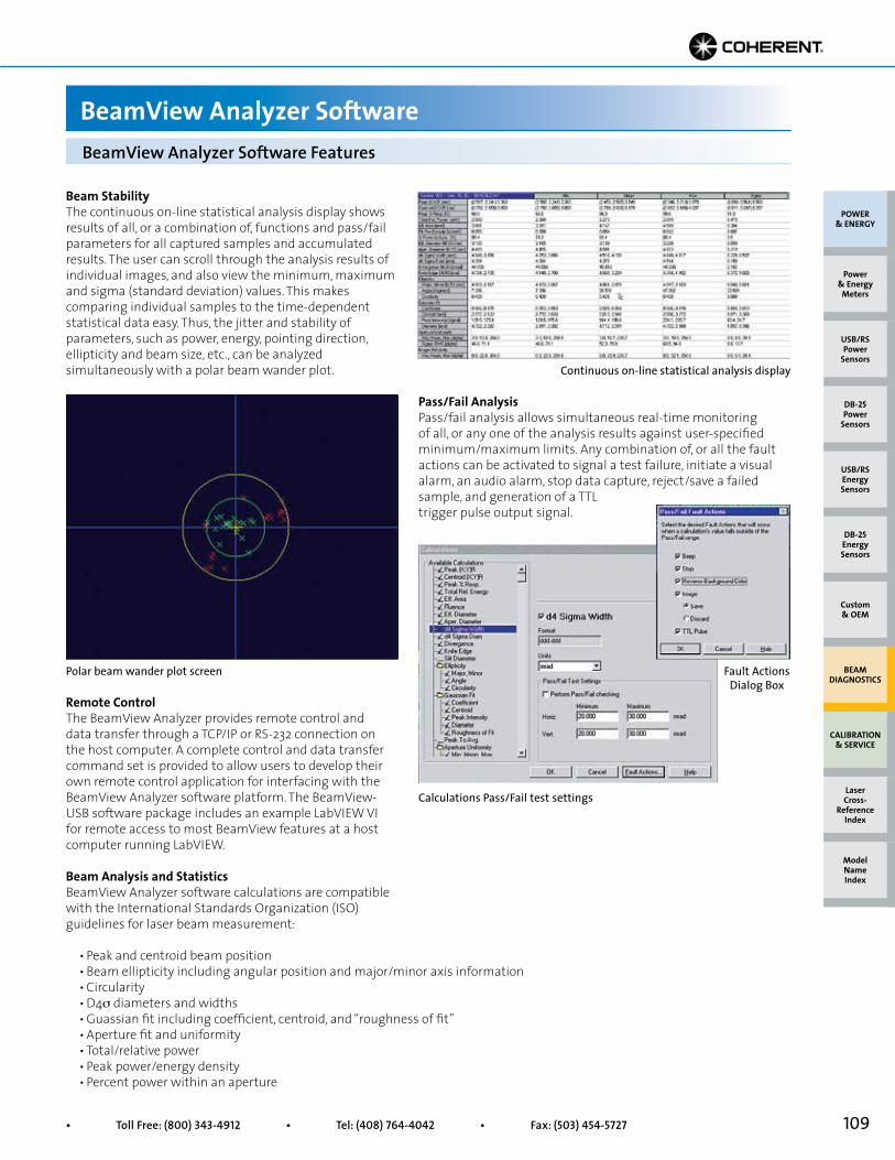
109• Toll Free: (800) 343-4912 • Tel: (408) 764-4042 • Fax: (503) 454-5727
Remote ControlThe BeamView Analyzer provides remote control and data transfer through a TCP/IP or RS-232 connection on the host computer. A complete control and data transfer command set is provided to allow users to develop their own remote control application for interfacing with the BeamView Analyzer software platform. The BeamView- USB software package includes an example LabVIEW VI for remote access to most BeamView features at a host computer running LabVIEW.
Beam Analysis and Statistics BeamView Analyzer software calculations are compatible with the International Standards Organization (ISO) guidelines for laser beam measurement:
• Peak and centroid beam position • Beam ellipticity including angular position and major/minor axis information • Circularity • D4σ diameters and widths • Guassian fit including coefficient, centroid, and “roughness of fit” • Aperture fit and uniformity • Total/relative power • Peak power/energy density • Percent power within an aperture
Continuous on-line statistical analysis display
Calculations Pass/Fail test settings
Polar beam wander plot screen Fault Actions Dialog Box
Beam StabilityThe continuous on-line statistical analysis display showsresults of all, or a combination of, functions and pass/failparameters for all captured samples and accumulatedresults. The user can scroll through the analysis results ofindividual images, and also view the minimum, maximumand sigma (standard deviation) values. This makes comparing individual samples to the time-dependentstatistical data easy. Thus, the jitter and stability of parameters, such as power, energy, pointing direction,ellipticity and beam size, etc., can be analyzed simultaneously with a polar beam wander plot.
Pass/Fail Analysis Pass/fail analysis allows simultaneous real-time monitoring of all, or any one of the analysis results against user-specified minimum/maximum limits. Any combination of, or all the fault actions can be activated to signal a test failure, initiate a visual alarm, an audio alarm, stop data capture, reject/save a failed sample, and generation of a TTL trigger pulse output signal.
BeamView Analyzer Software Features
BeamView Analyzer Software
POWER & ENERGY
Custom & OEM
BEAM DIAGNOSTICS
CALIBRATION & SERVICE
Power & Energy
Meters
Laser Cross-
Reference Index
Model Name Index
DB-25Energy Sensors
USB/RSEnergy Sensors
DB-25Power
Sensors
USB/RSPower
Sensors

110 Superior Reliability & Performance • www.Coherent.com • [email protected]
Analysis, On-Line Pass/Fail Tests • Centroid position/wander • Peak intensity/position • Peak-to-average intensity • Beam diameter/widths (selectable): - Second moment (d4 Sigma) - Knife-edge - Slit - Aperture diameter - Effective diameter • Flat Top analysis (new in BeamView-USB 4.4): - Beam uniformity - Plateau uniformity - Flatness factor - Effective irradiation area - Edge steepness - Effective average power/energy Density • Gaussian fits with: - Correlation coefficient - Diameter - Centroid - Peak intensity - Fit roughness • Ellipticity at intensity slice: - Major and minor axis diameter - Circularity (major/minor) - Axis orientation (rotation) - Auto align profiles to axis • Aperture analysis for circular, square, rectangular and elliptical beams: - % power/energy in aperture - Uniformity in aperture - Aperture/diameter tracking
Interactive Display Functions • On-line help • Report generation: - Report (.pdf) - BeamView window (screen capture) • Stored image paging • Reference profile select • Reference coordinate set • Background subtraction • Run/stop data analysis
• Selectable calculation area • On-line statistical analysis (all results): - Minimum, average, maximum - Sigma (standard deviation) • Pass/Fail test with fault action (all results): - Ratio - Audio/visual alarms - Save/reject images - TTL pulse out - Stop data capture • Image averaging • Peak energy/power density • Relative energy/power • Effective area • Divergence at % energy/power
BeamView Analyzer Software Features Summary
BeamView Analyzer Software
• Control of cursors, profiles, aperture, position, rotation and size • Live video on/off • 7 zoom levels • Image and profile autoscale modes • Auto peak/centroid locate • “Hot” function keys
POWER & ENERGY
Custom & OEM
BEAM DIAGNOSTICS
CALIBRATION & SERVICE
Power & Energy
Meters
Laser Cross-
Reference Index
Model Name Index
DB-25Energy Sensors
USB/RSEnergy Sensors
DB-25Power
Sensors
USB/RSPower
Sensors
111• Toll Free: (800) 343-4912 • Tel: (408) 764-4042 • Fax: (503) 454-5727
Image Capture and Storage • Pulsed or CW (continuous) analysis • Multi-channel (not simultaneous) camera input • Support for multiple camera types • Adjustable camera exposure time • RS-232 and TCP/IP communication protocols • Multiple trigger modes: - External trigger input - Autotrigger to a selected level • 3 resolution modes with the LaserCam-HR and LaserCam-HR-UV cameras: - 1280 x 1024 x 10 - 640 x 512 x 10 - 640 x 512 x 8 • 1 resolution mode with the LaserCam-HR-InGaAs camera: - 320 x 256 x 14 • Various capture modes: - Continuous - Time interval - On command (keypress)
Calibration Functions • Fully automatic background map correction (pixel-by-pixel) with bias offset • Automatic background monitor and warning • Optical scale factor (magnification/reduction) • Far-field optic focal length • Power/energy calibration factor
Standard Graphics Feature • Contour map with profiles/aperture overlay: - 3 plot types (contour/2D, 3D, Polar) - 4 scaling levels (fixed, scale-to-peak, low intensity, high intensity) - 4 style settings (gray, smooth, sharp, shaded bands) • Live video mode • Calculation inclusion area display • Profile/peak/centroid position cursor • Graphic zoom • Auto-scale 2D or profile intensity • Polar beam wander plot
• High-speed sample mode capture • Profile storage • Configuration storage with password protection • Image data file formats in binary (bin), ASCII (img), bmp, jpg, png, tif
BeamView Analyzer SoftwareBeamView Analyzer Software Features Summary
• On/off axis simultaneous display of: - Position cursor - Cross-section profiles - Gaussian fit profiles - Reference profiles - Aperture overlay for: • Beam uniformity • % energy/power • Rotatable color 3D isometric plot - 360°, 90° rotate/tilt - Hidden/transparent wire - Selectable wire density - Solid or single color - Auto-rotate mode
POWER & ENERGY
Custom & OEM
BEAM DIAGNOSTICS
CALIBRATION & SERVICE
Power & Energy
Meters
Laser Cross-
Reference Index
Model Name Index
DB-25Energy Sensors
USB/RSEnergy Sensors
DB-25Power
Sensors
USB/RSPower
Sensors
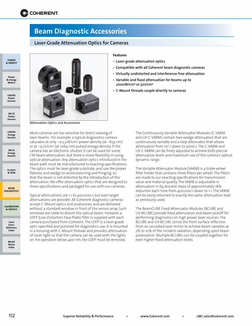
112 Superior Reliability & Performance • www.Coherent.com • [email protected]
Beam Diagnostic Accessories
Features• Laser-grade attenuation optics• Compatible with all Coherent beam diagnostic cameras• Virtually undistorted and interference-free attenuation• Variable and fixed attenuation for beams up to 2000W/cm2 or 50J/cm2
• C-Mount threads couple directly to cameras
Attenuation Optics and Accessories
Most cameras are too sensitive for direct viewing oflaser beams. For example, a typical diagnostics camerasaturates at only ~0.5 µW/cm2 power density (at ~633 nm) or at ~9 nJ/cm2 (at 1064 nm) pulsed energy density. If the camera has an electronic shutter, it can be used for some CW beam attenuation, but there is more flexibility in using optical attenuation. Any attenuation optics introduced in the beam path must be manufactured to exacting specifications. The optics must be laser-grade substrate, and use the proper flatness and wedge to avoid etaloning and fringing, so that the beam is not distorted by the introduction of the attenuation. We offer attenuation optics that are designed to these specifications and packaged for use with our cameras.
Typical attenuations are 1:1 to 400,000:1, but even largerattenuations are possible. All Coherent diagnostic cameras accept C-Mount optics and accessories, and are delivered without a standard window in front of the sensor array. Such windows are liable to distort the optical beam. However, a LDFP (Low-Distortion Face Plate) filter is supplied with each camera purchased from Coherent. The LDFP is a laser-grade optic specified and polished for diagnostics use. It is mounted in a housing with C-Mount threads and provides attenuation of room light so that the camera can be used with the lights on. For operation below 400 nm, the LDFP must be removed.
The Continuously Variable Attenuator Modules (C-VARMand UV C-VARM) contain two wedge attenuators that are continuously variable and a step attenuator that allows attenuation from 107:1 down to 3000:1. The C-VARM and UV C-VARM can be finely adjusted to achieve both precise attenuation levels and maximum use of the camera’s optical dynamic range.
The Variable Attenuator Module (VARM) is a triple-wheelfilter holder that contains three filters per wheel. The filters are made to our exacting specifications for transmission value and material quality. The VARM is adjustable in attenuation in 64 discrete steps of approximately 16% reduction each time from 400,000:1 down to 1:1. The VARM can be easily returned to exactly the same attenuation level as previously used.
The BeamCUBE Fixed-Attenuator Modules (BCUBE andUV-BCUBE) provide fixed attenuation and beam pickoff for performing diagnostics on high power laser sources. The BCUBE and UV-BCUBE utilize the front surface reflection from an uncoated laser mirror to achieve beam samples at 2% to 10% of the incident radiation, depending upon beam polarization. Multiple BCUBEs can be coupled together for even higher fixed attenuation levels.
Laser-Grade Attenuation Optics for Cameras
POWER & ENERGY
Custom & OEM
BEAM DIAGNOSTICS
CALIBRATION & SERVICE
Power & Energy
Meters
Laser Cross-
Reference Index
Model Name Index
DB-25Energy Sensors
USB/RSEnergy Sensors
DB-25Power
Sensors
USB/RSPower
Sensors

113• Toll Free: (800) 343-4912 • Tel: (408) 764-4042 • Fax: (503) 454-5727
VARM, LaserCam-HR-InGaAs, C-VARM, BCUBE, C-Mount Flanges and Barrel
In general, a camera cannot sense less than ~λ/4 total distortion in the beam, so if a series of filters is used, they must be made to very exacting laser-grade specifications. Attenuating optics from Coherent are manufactured to better than a λ/10 surface specification, so at least six optics in series can be used. Calculate the Low-Distortion Face Plate (LDFP) and each BCUBE as one optic, and the VARM or C-VARM as three optics each.
BCUBE, UV-BCUBE, VARM, C-VARM, UV C-VARM and all other Coherent cameras have female C-Mount threading, making them easy to connect with the male C-Mount connection flange provided with each attenuator. Also, all attenuators have 1/4-20 tapped holes for independent post or plate mounting.
The C-Mount flanges (threaded rings) also have a female RMS microscope thread. This allows a microscope objective to be coupled to the attenuators and extension barrels in order to create a flexible close-up imaging system for analysis of small/focused beams, fiber optics, laser diodes or LEDs.
Avoiding Multi-Filter Beam DistortionThe wavefront distortion through a number of optical filters can be calculated by taking the square root of the sum of the squares of the wavefront distortion of the individual components. For example, if the individual optics are made to λ/10 specifications and six are used, a total λ/4 RMS wavefront distortion will be introduced to the beam:
t = Transmission Value
t = 1.00
t = 1.00
t = 1.00
Laser Beamline
C-Mount Thread
50 mm(1.97 in.)
70 mm(2.76 in.)
86 mm(3.39 in.) 40 mm
(1.57 in.)INFIXED ATTENUATION
VARIABLE ATTENUATION
MAX
MINMAX
MIN
OUT
79.4 mm (3.13 in.)63.5 mm (2.5 in.)
58.7 mm (2.3 in.)
57.1 mm(2.25 in.) 44.5 mm
(1.75 in.)
C-MountThread
OU
TIN
5%
40.6 mm(1.6 in.)
61 mm (2.4 in.)
45.7 mm(1.8 in.)
46 mm(1.8 in.)
C-MountThread
VARMC-VARM and UV C-VARM BCUBE and UV-BCUBE
Attenuation Optics for Cameras
Beam Diagnostic Accessories
0.12 + 0.12 + 0.12 + 0.12 + 0.12 + 0.12 = 0.25
Model VARM C-VARM UV C-VARM BCUBE UV-BCUBE BARREL SET (Barrels, 3 C-Mount Flanges)Wavelength Min. (nm) 380 380 190 380 190 – Max. (nm) 2200 2200 1100 2200 2200 –Attenuation From 4 x 10⁵:1 107:1 105:1 50:1 50:1 – To 1:1 3000:1 300:1 10:1 10:1 –Aperture (mm) 19 15 15 19 19 –Max. Power Density (W/cm2) 1* 1* 1* 2.0 x 109 2.0 x 10⁹ –Max. Energy Density (J/cm2) 0.1* 0.1* 0.008 50 50 –Beam Offset (mm) – – – 4.0 4.0 –Part Number 33-3328-000 33-3336-000** 33-6859-000** 1098403** 1098466 1098426
Device Specifications
* The maximum power and energy density listed are the levels at which thermal lensing occurs.** C24 Quick Ship program: eligible for next business day shipment.
Attenuator SelectionAttenuation is selected on the basis of power density in W/cm2 or energy density in J/cm2. The attenuation from the camera’s Low-Distortion Face Plate (LDFP) will allow an average power density of up to 1.2 mW/cm2. There are then only two more steps to attenuation selection:
1) Choose either the VARM or the C-VARM for up to 1W/cm2.2) In addition or alternatively, use a BCUBE beamsplitter module to pick off between 2% and 10% of the beam (depending on polarization and wavelength).
POWER & ENERGY
Custom & OEM
BEAM DIAGNOSTICS
CALIBRATION & SERVICE
Power & Energy
Meters
Laser Cross-
Reference Index
Model Name Index
DB-25Energy Sensors
USB/RSEnergy Sensors
DB-25Power
Sensors
USB/RSPower
Sensors
**
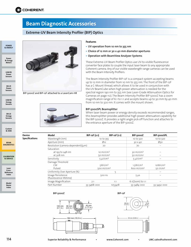
114 Superior Reliability & Performance • www.Coherent.com • [email protected]
Beam Diagnostic Accessories
BIP-5000Z and BIP-12F attached to a LaserCam-HR
BIP-5000Z BIP-12F
Features• UV operation from 10 nm to 355 nm• Choice of 12 mm or 30 x 40 mm diameter apertures• Operation with BeamView Analyzer Systems
These Extreme-UV Beam Profiler Optics use UV-to-visible fluorescence converter face plates to couple the input laser beam to any appropriate Coherent camera. Any of our visible wavelength range cameras can be used with the Beam Intensity Profilers.
The Beam Intensity Profiler BIP-12F is a compact system accepting beams up to 12 mm in diameter from 10 nm to 355 nm. The front of the BIP-12F has a C-Mount thread, which allows it to be used in conjunction with the UV BeamCube when high power attenuation is needed for the spectral region 190 nm to 355 nm (see Laser-Grade Attenuation Optics for Cameras on page 112). The Beam Intensity Profiler BIP-5000Z has a zoom magnification range of 6:1 to 1:1 and accepts beams up to 30 mm by 40 mm from 10 nm to 320 nm. It comes with the mount shown.
BIP-5000SPL BeamsplitterWhen laser beam power or energy density exceeds recommended ranges, this beamsplitter provides additional high power attenuation capability for the BIP-5000Z. It provides a right-angle pick-off function and attaches to the entrance aperture of the BIP-5000Z.
90 mm(3.5 in.)
45 mm(1.77 in.)103 mm
(4.1 in.)
394 mm (15.5 in.)
12 mm(0.47 in.)
38 mm(1.5 in.)
93 mm (3.66 in.)
Extreme-UV Beam Intensity Profiler (BIP) Optics
Model BIP-12F (2:1) BIP-12F (1:1) BIP-5000Z BIP-5000SPL Wavelength (nm) 10 to 355 10 to 320 10 to 320Aperture (mm) Ø12 30 x 40 Ø50Resolution (camera-dependent)(µm) 20 70 –Saturation at 193 to 248 nm 10 mJ/cm2 30 mJ/cm2 – at 308 nm 50 mJ/cm2 50 mJ/cm2 –Sensitivity 5 µJ/cm2 5 µJ/cm2 –Damage Threshold CW 5W/cm2 1.5W/cm2 10W/cm2
Pulsed 500 mJ/cm2 600 mJ/cm2 50 J/cm2
Uniformity Over Aperture (%) 5 –Image Persistence 500 ns 5 µs –(fluorescence lifetime)Image Magnification 2:1 1:1 6:1(Zoom) to 1:1 –Part Number 33-3468-000 1053418 33-3484-000 33-3492-000
Device Specifications
POWER & ENERGY
Custom & OEM
BEAM DIAGNOSTICS
CALIBRATION & SERVICE
Power & Energy
Meters
Laser Cross-
Reference Index
Model Name Index
DB-25Energy Sensors
USB/RSEnergy Sensors
DB-25Power
Sensors
USB/RSPower
Sensors
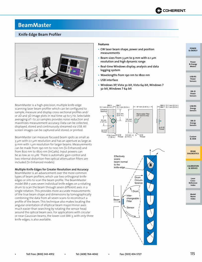
115• Toll Free: (800) 343-4912 • Tel: (408) 764-4042 • Fax: (503) 454-5727
Features• CW laser beam shape, power and position measurements• Beam sizes from 3 µm to 9 mm with 0.1 µm resolution and high dynamic range• Real-time Windows display, analysis and data logging system• Wavelengths from 190 nm to 1800 nm• USB interface• Windows XP, Vista 32-bit, Vista 64-bit, Windows 7 32-bit, Windows 7 64-bit
BeamMaster is a high-precision, multiple knife-edge scanning laser beam profiler which can be configured to sample, measure and display cross-sectional profiles and/or 2D and 3D image plots in real time up to 5 Hz. Selectable averaging of 1 to 20 samples provides noise reduction and maximizes measurement accuracy. Data can be collected, displayed, stored and continuously streamed via USB. All screen images can be captured and stored, or printed.
BeamMaster can measure focused beam spots as small as 3 µm with 0.1 µm resolution and has an aperture as large as 9 mm with 1 µm resolution for larger beams. Measurements can be made from 190 nm to 1100 nm (Si-Enhanced) and from 800 nm to 1800 nm (InGaAs). Input powers can be as low as 10 µW. There is automatic gain control and two internal distortion-free optical attenuation filters are included (Si-Enhanced models)
Multiple Knife-Edges for Greater Resolution and AccuracyBeamMaster is an advancement over the more common types of beam profilers, which use two orthogonal knife-edges or slits to scan the beam profile. The BeamMaster model BM-7 uses seven individual knife-edges on a rotating drum to scan the beam through seven different axes in a single rotation. This provides more accurate measurements of the true beam shape and dimensions by tomographically combining the data from all seven scans to reconstruct a profile of the beam. This technique also makes locating the angular orientation of elliptical beam major/minor axes much easier than searching by rotating the sensor head around the optical beam axis. For applications with circular or near-Gaussian beams, the lower-cost BM-3, with only three knife-edges, is also available.
105 mm(4.13 in.)
3.5 mm(0.14 in.)
50 mm(1.97 in.)
87 mm (3.43 in.)
35.2 mm(1.39 in.)
52.5 mm(2.07 in.)
2x 8-32Thread
8-32Thread
EntranceAperture
Removable Filter(UV and Si only)
BM-7: 15.1 mm (0.6 in.)
BM-3: 13.1 mm (0.5 in.)
BM-3: 13.1 mm (0.5 in.)BM-7: 15.1 mm (0.6 in.)
3x 8-32Thread
8-32Thread
Knife-Edge Beam Profiler
BeamMaster
Effectivelyscansbeam normalto theknife-edge
DrumCircum-ference
Drum
Inter-changeableFilter
Sensor
Beam
POWER & ENERGY
Custom & OEM
BEAM DIAGNOSTICS
CALIBRATION & SERVICE
Power & Energy
Meters
Laser Cross-
Reference Index
Model Name Index
DB-25Energy Sensors
USB/RSEnergy Sensors
DB-25Power
Sensors
USB/RSPower
Sensors
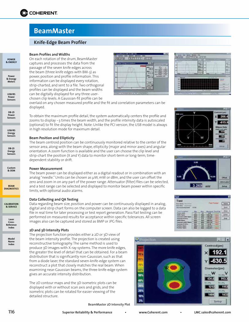
116 Superior Reliability & Performance • www.Coherent.com • [email protected]
BeamMaster
Beam Profiles and WidthsOn each rotation of the drum, BeamMaster captures and processes the data from the passage of the seven knife edges across the beam (three knife edges with BM-3) as power, position and profile information. This information can be displayed every rotation, strip-charted, and sent to a file. Two orthogonal profiles can be displayed and the beam widths can be digitally displayed for any three user-chosen clip levels. A Gaussian-fit profile can be
Knife-Edge Beam Profiler
overlaid on any chosen measured profile and the fit and correlation parameters can be displayed.
To obtain the maximum profile detail, the system automatically centers the profile and zooms to display ~3 times the beam width, and the profile intensity data is autoscaled (optional) to fit the display height. Note: Unlike the PCI version, the USB model is always in high resolution mode for maximum detail.
Beam Position and EllipticityThe beam centroid position can be continuously monitored relative to the center of the sensor area, along with the beam shape, ellipticity (major and minor axes) and angular orientation. A zoom function is available and the user can choose the clip level and strip-chart the position (X and Y) data to monitor short-term or long-term, time-dependent stability or drift.
Power MeasurementThe beam power can be displayed either as a digital readout or in combination with an analog “needle.” Units can be chosen as µW, mW or dBm, and the user can offset the zero and zoom in on any part of the power range. Attenuator (filter) files can be selected, and a test range can be selected and displayed to monitor beam power within specific limits, with optional audio alarms.
Data Collecting and QA TestingData regarding beam size, position and power can be continuously displayed in analog, digital and strip chart forms on the computer screen. Data can also be logged to a data file in real time for later processing or test report generation. Pass/Fail testing can be performed on measured results for acceptance within specific tolerances. All screen images also can be captured and stored as BMP or JPG files.
2D and 3D Intensity PlotsThe projection function provides either a 2D or 3D view of the beam intensity profile. The projection is created using reconstructive tomography. The same method is used to produce 3D images with X-ray systems. The more knife edges, the greater the level of detail that can be obtained. For a beam distribution that is significantly non-Gaussian, such as that from a diode laser, the standard seven-knife-edge system can reconstruct a plot that closely matches the real beam. When examining near-Gaussian beams, the three-knife-edge system gives an accurate intensity distribution.
The 2D contour maps and the 3D isometric plots can be displayed with or without scan axis and grids, and the isometric plots can be rotated for easier viewing of the detailed structure.
BeamMaster 2D Intensity Plot
POWER & ENERGY
Custom & OEM
BEAM DIAGNOSTICS
CALIBRATION & SERVICE
Power & Energy
Meters
Laser Cross-
Reference Index
Model Name Index
DB-25Energy Sensors
USB/RSEnergy Sensors
DB-25Power
Sensors
USB/RSPower
Sensors
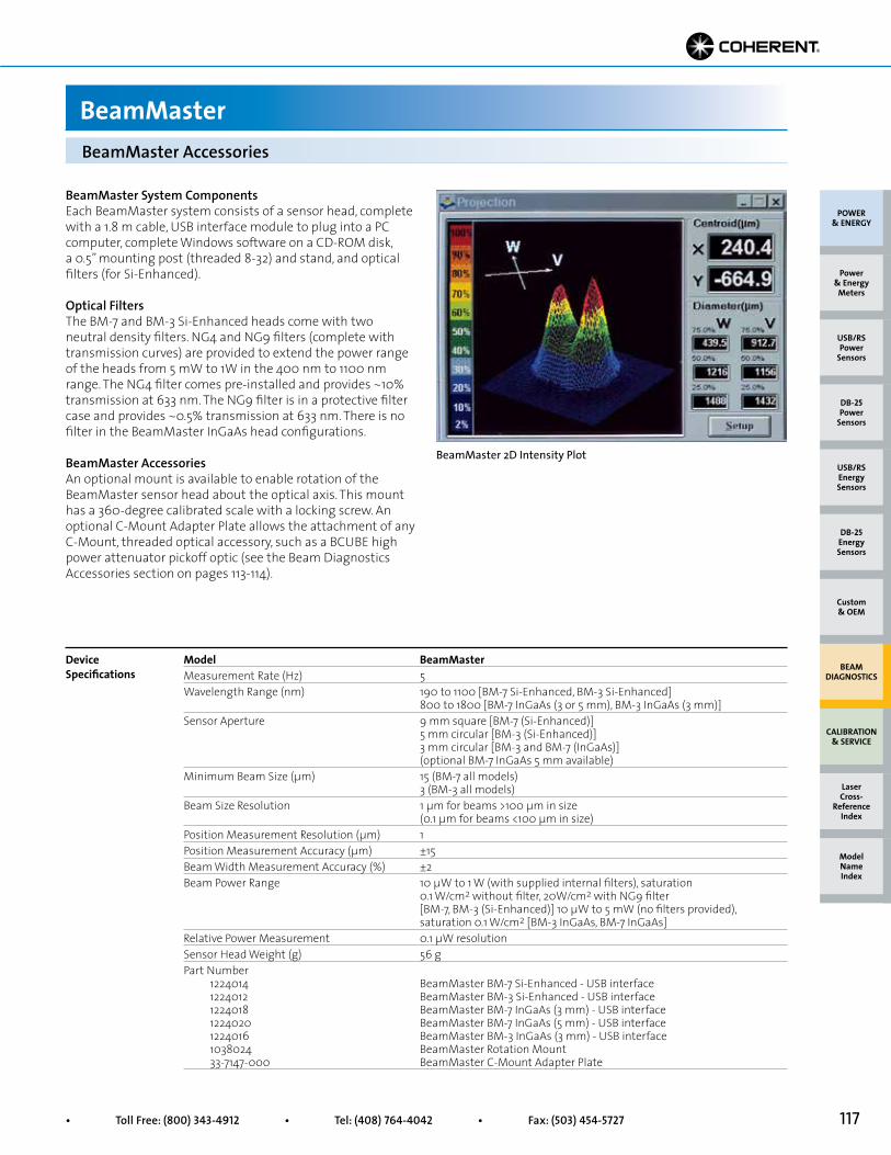
117• Toll Free: (800) 343-4912 • Tel: (408) 764-4042 • Fax: (503) 454-5727
BeamMaster Accessories
BeamMaster
Model BeamMasterMeasurement Rate (Hz) 5Wavelength Range (nm) 190 to 1100 [BM-7 Si-Enhanced, BM-3 Si-Enhanced] 800 to 1800 [BM-7 InGaAs (3 or 5 mm), BM-3 InGaAs (3 mm)]Sensor Aperture 9 mm square [BM-7 (Si-Enhanced)] 5 mm circular [BM-3 (Si-Enhanced)] 3 mm circular [BM-3 and BM-7 (InGaAs)] (optional BM-7 InGaAs 5 mm available)Minimum Beam Size (µm) 15 (BM-7 all models) 3 (BM-3 all models)Beam Size Resolution 1 µm for beams >100 µm in size (0.1 µm for beams <100 µm in size)Position Measurement Resolution (µm) 1Position Measurement Accuracy (µm) ±15Beam Width Measurement Accuracy (%) ±2Beam Power Range 10 µW to 1 W (with supplied internal filters), saturation 0.1 W/cm2 without filter, 20W/cm2 with NG9 filter [BM-7, BM-3 (Si-Enhanced)] 10 µW to 5 mW (no filters provided), saturation 0.1 W/cm2 [BM-3 InGaAs, BM-7 InGaAs]Relative Power Measurement 0.1 µW resolutionSensor Head Weight (g) 56 gPart Number 1224014 BeamMaster BM-7 Si-Enhanced - USB interface 1224012 BeamMaster BM-3 Si-Enhanced - USB interface 1224018 BeamMaster BM-7 InGaAs (3 mm) - USB interface 1224020 BeamMaster BM-7 InGaAs (5 mm) - USB interface 1224016 BeamMaster BM-3 InGaAs (3 mm) - USB interface 1038024 BeamMaster Rotation Mount 33-7147-000 BeamMaster C-Mount Adapter Plate
Device Specifications
BeamMaster System ComponentsEach BeamMaster system consists of a sensor head, complete with a 1.8 m cable, USB interface module to plug into a PC computer, complete Windows software on a CD-ROM disk, a 0.5” mounting post (threaded 8-32) and stand, and optical filters (for Si-Enhanced).
Optical FiltersThe BM-7 and BM-3 Si-Enhanced heads come with two neutral density filters. NG4 and NG9 filters (complete with transmission curves) are provided to extend the power range of the heads from 5 mW to 1W in the 400 nm to 1100 nm range. The NG4 filter comes pre-installed and provides ~10% transmission at 633 nm. The NG9 filter is in a protective filter case and provides ~0.5% transmission at 633 nm. There is no filter in the BeamMaster InGaAs head configurations.
BeamMaster AccessoriesAn optional mount is available to enable rotation of the BeamMaster sensor head about the optical axis. This mount has a 360-degree calibrated scale with a locking screw. An optional C-Mount Adapter Plate allows the attachment of any C-Mount, threaded optical accessory, such as a BCUBE high power attenuator pickoff optic (see the Beam Diagnostics Accessories section on pages 113-114).
BeamMaster 2D Intensity Plot
POWER & ENERGY
Custom & OEM
BEAM DIAGNOSTICS
CALIBRATION & SERVICE
Power & Energy
Meters
Laser Cross-
Reference Index
Model Name Index
DB-25Energy Sensors
USB/RSEnergy Sensors
DB-25Power
Sensors
USB/RSPower
Sensors
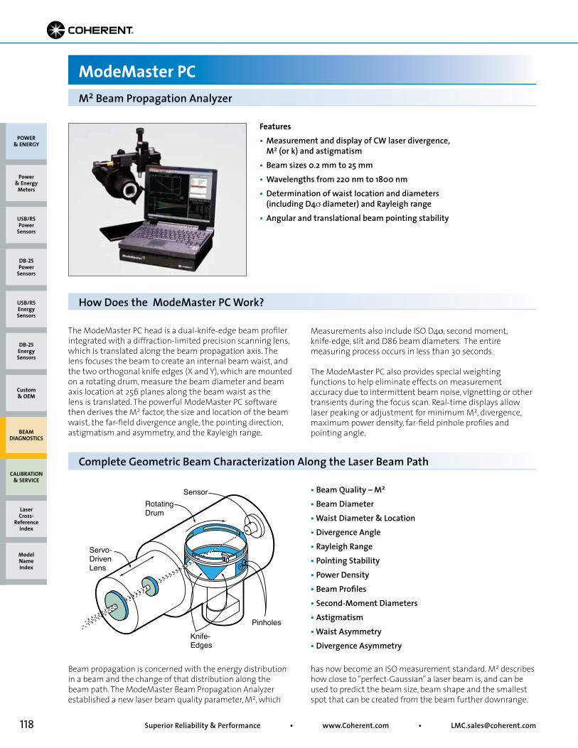
118 Superior Reliability & Performance • www.Coherent.com • [email protected]
Features• Measurement and display of CW laser divergence, M2 (or k) and astigmatism• Beam sizes 0.2 mm to 25 mm• Wavelengths from 220 nm to 1800 nm• Determination of waist location and diameters (including D4σ diameter) and Rayleigh range• Angular and translational beam pointing stability
M2 Beam Propagation Analyzer
ModeMaster PC
The ModeMaster PC head is a dual-knife-edge beam profiler integrated with a diffraction-limited precision scanning lens, which is translated along the beam propagation axis. The lens focuses the beam to create an internal beam waist, and the two orthogonal knife edges (X and Y), which are mounted on a rotating drum, measure the beam diameter and beam axis location at 256 planes along the beam waist as the lens is translated. The powerful ModeMaster PC software then derives the M2 factor, the size and location of the beam waist, the far-field divergence angle, the pointing direction, astigmatism and asymmetry, and the Rayleigh range.
Knife-Edges
Pinholes
SensorRotatingDrum
Servo-DrivenLens
• Beam Quality – M2
• Beam Diameter• Waist Diameter & Location• Divergence Angle• Rayleigh Range• Pointing Stability• Power Density• Beam Profiles• Second-Moment Diameters• Astigmatism• Waist Asymmetry• Divergence Asymmetry
Beam propagation is concerned with the energy distribution in a beam and the change of that distribution along the beam path. The ModeMaster Beam Propagation Analyzer established a new laser beam quality parameter, M2, which
has now become an ISO measurement standard. M2 describes how close to “perfect-Gaussian” a laser beam is, and can be used to predict the beam size, beam shape and the smallest spot that can be created from the beam further downrange.
Measurements also include ISO D4σ, second moment, knife-edge, slit and D86 beam diameters. The entire measuring process occurs in less than 30 seconds.
The ModeMaster PC also provides special weighting functions to help eliminate effects on measurement accuracy due to intermittent beam noise, vignetting or other transients during the focus scan. Real-time displays allow laser peaking or adjustment for minimum M2, divergence, maximum power density, far-field pinhole profiles and pointing angle.
How Does the ModeMaster PC Work?
Complete Geometric Beam Characterization Along the Laser Beam Path
POWER & ENERGY
Custom & OEM
BEAM DIAGNOSTICS
CALIBRATION & SERVICE
Power & Energy
Meters
Laser Cross-
Reference Index
Model Name Index
DB-25Energy Sensors
USB/RSEnergy Sensors
DB-25Power
Sensors
USB/RSPower
Sensors
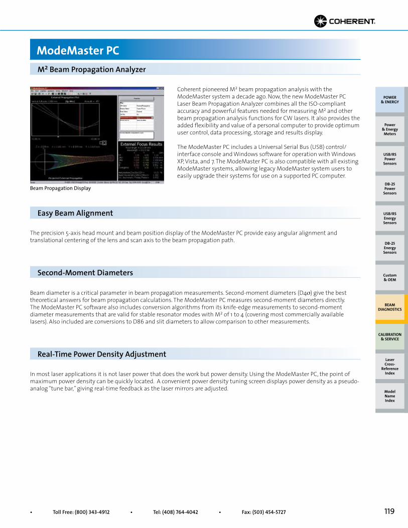
119• Toll Free: (800) 343-4912 • Tel: (408) 764-4042 • Fax: (503) 454-5727
Beam Propagation Display
Coherent pioneered M2 beam propagation analysis with the ModeMaster system a decade ago. Now, the new ModeMaster PC Laser Beam Propagation Analyzer combines all the ISO-compliant accuracy and powerful features needed for measuring M2 and other beam propagation analysis functions for CW lasers. It also provides the added flexibility and value of a personal computer to provide optimum user control, data processing, storage and results display.
The ModeMaster PC includes a Universal Serial Bus (USB) control/interface console and Windows software for operation with Windows XP, Vista, and 7. The ModeMaster PC is also compatible with all existing ModeMaster systems, allowing legacy ModeMaster system users to easily upgrade their systems for use on a supported PC computer.
The precision 5-axis head mount and beam position display of the ModeMaster PC provide easy angular alignment and translational centering of the lens and scan axis to the beam propagation path.
Beam diameter is a critical parameter in beam propagation measurements. Second-moment diameters (D4σ) give the best theoretical answers for beam propagation calculations. The ModeMaster PC measures second-moment diameters directly. The ModeMaster PC software also includes conversion algorithms from its knife-edge measurements to second-moment diameter measurements that are valid for stable resonator modes with M2 of 1 to 4 (covering most commercially available lasers). Also included are conversions to D86 and slit diameters to allow comparison to other measurements.
In most laser applications it is not laser power that does the work but power density. Using the ModeMaster PC, the point of maximum power density can be quickly located. A convenient power density tuning screen displays power density as a pseudo-analog “tune bar,” giving real-time feedback as the laser mirrors are adjusted.
M2 Beam Propagation Analyzer
ModeMaster PC
Easy Beam Alignment
Second-Moment Diameters
Real-Time Power Density Adjustment
POWER & ENERGY
Custom & OEM
BEAM DIAGNOSTICS
CALIBRATION & SERVICE
Power & Energy
Meters
Laser Cross-
Reference Index
Model Name Index
DB-25Energy Sensors
USB/RSEnergy Sensors
DB-25Power
Sensors
USB/RSPower
Sensors

120 Superior Reliability & Performance • www.Coherent.com • [email protected]
Real-Time Display Pointing-Stability Display
Real-Time M2 and Beam ProfilesThe ModeMaster PC provides real-time measurement and display for fine tuning M2 and many other beam propagation parameters, as well as the near-field or far-field pinhole intensity beam profiles.
Beam Pointing and Translational StabilityModeMaster is able to measure and display both translational (parallel to the beam axis) or angular (from a pivot point) beam movement over a period of 2 minutes to 24 hours. The angular pivot point of the beam axis (often a single optical surface) can be located along the beam path. Statistical analysisof the beam axis location and angle are displayed for both the X and Y axes. Three levels of filtering reduce noise and increase the sensitivity of pointing-stability measurements.
Expanded Online HelpThe ModeMaster PC provides complete online help. Help messages also suggest corrective measures when beam parameter limits are exceeded.
Upgrading to the ModeMaster PCAll previous versions of the ModeMaster systems can be upgraded to the ModeMaster PC. The original console unit and the LabMaster display are simply replaced with the ModeMaster PC Control/Interface Module and Software, installed in a user-supplied compatible PC computer. All original ModeMaster scan heads are fully compatible and can be plugged into the ModeMaster PC Control/Interface Module, which can be ordered separately with the software.
Changes in the shape of a propagating beam can be astigmatic, asymmetric or both. The beam shown at the near right has pure astigmatism; the waists (W0) in the horizontal and vertical directions are the same size, but occur at different propagation distances (Z0). In asymmetric beams (far right) the two waists occur together, but are of different diameters. The ModeMaster PC provides complete analysis of these beam characteristics.
Pure AsymmetryZox = Zoy
Wox ≠ Woy
Pure AstigmatismZox ≠ Zoy
Wox = Woy
M2 Beam Propagation Analyzer
ModeMaster PC
Beam Astigmatism and Asymmetry
POWER & ENERGY
Custom & OEM
BEAM DIAGNOSTICS
CALIBRATION & SERVICE
Power & Energy
Meters
Laser Cross-
Reference Index
Model Name Index
DB-25Energy Sensors
USB/RSEnergy Sensors
DB-25Power
Sensors
USB/RSPower
Sensors
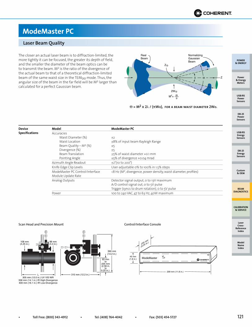
121• Toll Free: (800) 343-4912 • Tel: (408) 764-4042 • Fax: (503) 454-5727
The closer an actual laser beam is to diffraction-limited, the more tightly it can be focused, the greater its depth of field, and the smaller the diameter of the beam optics can be to transmit the beam. M2 is the ratio of the divergence of the actual beam to that of a theoretical diffraction-limited beam of the same waist size in the TEMoo mode. Thus, the angular size of the beam in the far field will be M2 larger than calculated for a perfect Gaussian beam.
NormalizingGaussianBeam
RealBeam
Z°
2W°Θθ
M2=
Zθ Θ
Θ = M2 x 2λ / (πWo), for a beam waist diameter 2Wo.
Laser Beam Quality
ModeMaster PC
108 mm(4.25 in.)
86 mm(3.4 in.)
310 mm (12.2 in.)
360 mm(14.2 in.)
65 mmto
235 mm(2.56 in.
to9.25 in.)
L305 mm (12.0 in.) UV VIS NIR
358 mm (14.1 in.) IR High-Divergence409 mm (16.1 in.) IR Low-Divergence
Scan Head and Precision Mount Control/Interface Console
Model ModeMaster PCAccuracies Waist Diameter (%) ±2 Waist Location ±8% of input beam Rayleigh Range Beam Quality – M2 (%) ±5 Divergence (%) ±5 Beam Translation ±5% of waist diameter +0.1 mm Pointing Angle ±5% of divergence +0.04 mradAzimuth Angle Readout ±2°(10 to 200°)Knife-Edge Clip Levels User-adjustable 0% to 100% in 1.5% stepsModeMaster PC Control/Interface <8 Hz (M2, divergence, power density, waist diameter, profiles)Module Update Rate Analog Outputs Detector signal output, 0 to 13V maximum A/D control signal out, 0 to 5V pulse Trigger (syncs to drum rotation), 0 to 5V pulsePower 100 to 240 VAC, 47 to 63 Hz, 40W maximum
Device Specifications
POWER & ENERGY
Custom & OEM
BEAM DIAGNOSTICS
CALIBRATION & SERVICE
Power & Energy
Meters
Laser Cross-
Reference Index
Model Name Index
DB-25Energy Sensors
USB/RSEnergy Sensors
DB-25Power
Sensors
USB/RSPower
Sensors
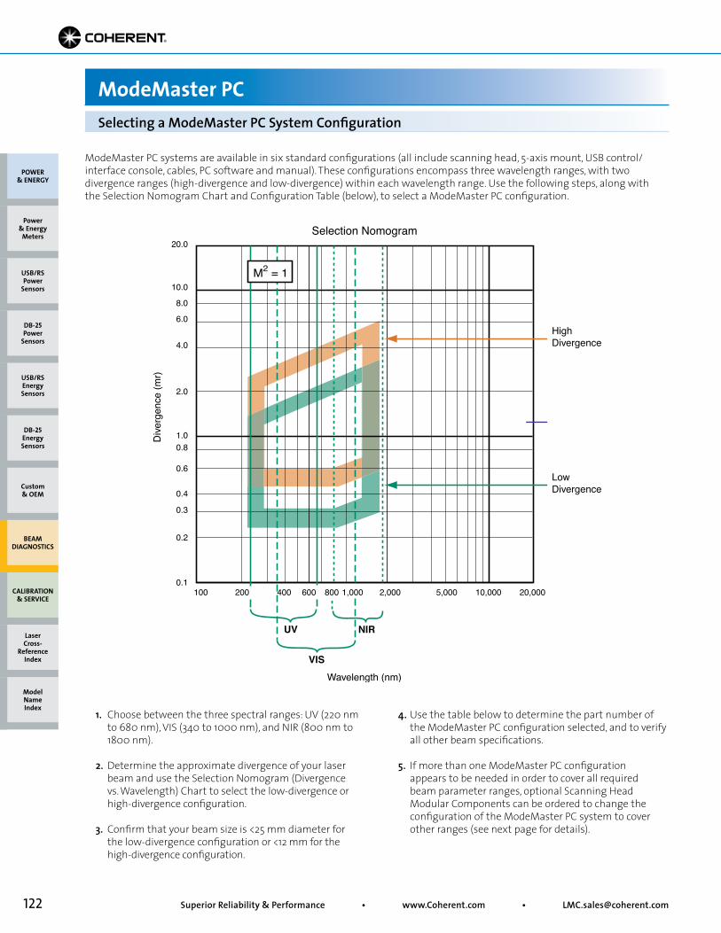
122 Superior Reliability & Performance • www.Coherent.com • [email protected]
ModeMaster PC systems are available in six standard configurations (all include scanning head, 5-axis mount, USB control/interface console, cables, PC software and manual). These configurations encompass three wavelength ranges, with two divergence ranges (high-divergence and low-divergence) within each wavelength range. Use the following steps, along with the Selection Nomogram Chart and Configuration Table (below), to select a ModeMaster PC configuration.
1. Choose between the three spectral ranges: UV (220 nm to 680 nm), VIS (340 to 1000 nm), and NIR (800 nm to 1800 nm). 2. Determine the approximate divergence of your laser beam and use the Selection Nomogram (Divergence vs. Wavelength) Chart to select the low-divergence or high-divergence configuration. 3. Confirm that your beam size is <25 mm diameter for the low-divergence configuration or <12 mm for the high-divergence configuration.
4. Use the table below to determine the part number of the ModeMaster PC configuration selected, and to verify all other beam specifications.
5. If more than one ModeMaster PC configuration appears to be needed in order to cover all required beam parameter ranges, optional Scanning Head Modular Components can be ordered to change the configuration of the ModeMaster PC system to cover other ranges (see next page for details).
100 200 400 600 800 1,000 2,000 5,000 10,000 20,0000.1
0.2
0.3
0.4
0.6
1.0
10.0
20.0
UV
VIS
NIR
0.8
2.0
4.0
6.0
8.0
Selection Nomogram
Wavelength (nm)
Dive
rgen
ce (m
r)
LowDivergence
HighDivergence
M2 = 1
Selecting a ModeMaster PC System Configuration
ModeMaster PC
POWER & ENERGY
Custom & OEM
BEAM DIAGNOSTICS
CALIBRATION & SERVICE
Power & Energy
Meters
Laser Cross-
Reference Index
Model Name Index
DB-25Energy Sensors
USB/RSEnergy Sensors
DB-25Power
Sensors
USB/RSPower
Sensors
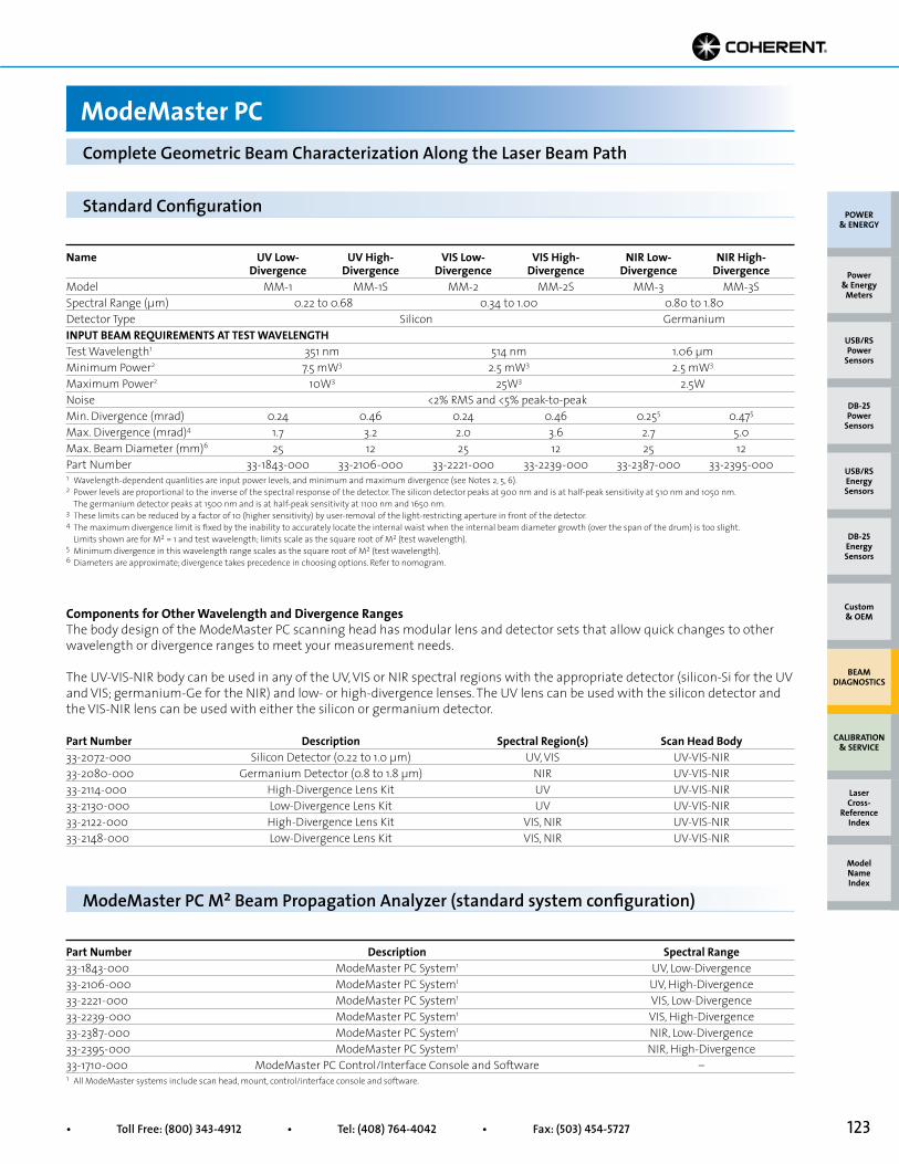
123• Toll Free: (800) 343-4912 • Tel: (408) 764-4042 • Fax: (503) 454-5727
Components for Other Wavelength and Divergence Ranges The body design of the ModeMaster PC scanning head has modular lens and detector sets that allow quick changes to other wavelength or divergence ranges to meet your measurement needs.
The UV-VIS-NIR body can be used in any of the UV, VIS or NIR spectral regions with the appropriate detector (silicon-Si for the UV and VIS; germanium-Ge for the NIR) and low- or high-divergence lenses. The UV lens can be used with the silicon detector and the VIS-NIR lens can be used with either the silicon or germanium detector.
Name UV Low- UV High- VIS Low- VIS High- NIR Low- NIR High- Divergence Divergence Divergence Divergence Divergence DivergenceModel MM-1 MM-1S MM-2 MM-2S MM-3 MM-3SSpectral Range (µm) 0.22 to 0.68 0.34 to 1.00 0.80 to 1.80Detector Type Silicon GermaniumINPUT BEAM REQUIREMENTS AT TEST WAVELENGTHTest Wavelength1 351 nm 514 nm 1.06 µmMinimum Power2 7.5 mW3 2.5 mW3 2.5 mW3
Maximum Power2 10W3 25W3 2.5WNoise <2% RMS and <5% peak-to-peakMin. Divergence (mrad) 0.24 0.46 0.24 0.46 0.255 0.475
Max. Divergence (mrad)4 1.7 3.2 2.0 3.6 2.7 5.0Max. Beam Diameter (mm)6 25 12 25 12 25 12Part Number 33-1843-000 33-2106-000 33-2221-000 33-2239-000 33-2387-000 33-2395-000
Standard Configuration
Complete Geometric Beam Characterization Along the Laser Beam Path
ModeMaster PC
1 Wavelength-dependent quanlities are input power levels, and minimum and maximum divergence (see Notes 2, 5, 6).2 Power levels are proportional to the inverse of the spectral response of the detector. The silicon detector peaks at 900 nm and is at half-peak sensitivity at 510 nm and 1050 nm. The germanium detector peaks at 1500 nm and is at half-peak sensitivity at 1100 nm and 1650 nm.3 These limits can be reduced by a factor of 10 (higher sensitivity) by user-removal of the light-restricting aperture in front of the detector.4 The maximum divergence limit is fixed by the inability to accurately locate the internal waist when the internal beam diameter growth (over the span of the drum) is too slight. Limits shown are for M2 = 1 and test wavelength; limits scale as the square root of M2 (test wavelength).5 Minimum divergence in this wavelength range scales as the square root of M2 (test wavelength).6 Diameters are approximate; divergence takes precedence in choosing options. Refer to nomogram.
Part Number Description Spectral Region(s) Scan Head Body33-2072-000 Silicon Detector (0.22 to 1.0 µm) UV, VIS UV-VIS-NIR33-2080-000 Germanium Detector (0.8 to 1.8 µm) NIR UV-VIS-NIR33-2114-000 High-Divergence Lens Kit UV UV-VIS-NIR33-2130-000 Low-Divergence Lens Kit UV UV-VIS-NIR33-2122-000 High-Divergence Lens Kit VIS, NIR UV-VIS-NIR33-2148-000 Low-Divergence Lens Kit VIS, NIR UV-VIS-NIR
POWER & ENERGY
Custom & OEM
BEAM DIAGNOSTICS
CALIBRATION & SERVICE
Power & Energy
Meters
Laser Cross-
Reference Index
Model Name Index
DB-25Energy Sensors
USB/RSEnergy Sensors
DB-25Power
Sensors
USB/RSPower
Sensors
Part Number Description Spectral Range33-1843-000 ModeMaster PC System1 UV, Low-Divergence33-2106-000 ModeMaster PC System1 UV, High-Divergence33-2221-000 ModeMaster PC System1 VIS, Low-Divergence33-2239-000 ModeMaster PC System1 VIS, High-Divergence33-2387-000 ModeMaster PC System1 NIR, Low-Divergence33-2395-000 ModeMaster PC System1 NIR, High-Divergence33-1710-000 ModeMaster PC Control/Interface Console and Software –
ModeMaster PC M2 Beam Propagation Analyzer (standard system configuration)
1 All ModeMaster systems include scan head, mount, control/interface console and software.
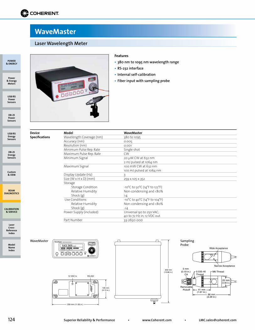
124 Superior Reliability & Performance • www.Coherent.com • [email protected]
Features• 380 nm to 1095 nm wavelength range• RS-232 interface• Internal self-calibration• Fiber input with sampling probe
Model WaveMasterWavelength Coverage (nm) 380 to 1095Accuracy (nm) 0.005Resolution (nm) 0.001Minimum Pulse Rep. Rate Single shotMaximum Pulse Rep. Rate CWMinimum Signal 20 µW CW at 632 nm 2 mJ pulsed at 1064 nmMaximum Signal 100 mW CW at 632 nm 100 mJ pulsed at 1064 nmDisplay Update (Hz) 3Size (W x H x D) (mm) 259 x 105 x 352Storage Storage Condition -10°C to 50°C (14°F to 122°F) Relative Humidity Non-condensing and <80% Shock (g) >4 Use Conditions -10°C to 40°C (14°F to 104°F) Relative Humidity Non-condensing and <80% Shock (g) <4Power Supply (included) Universal 90 to 250 VAC; 40 to 72 Hz in; 12 VDC outPart Number 33-2650-000
Device Specifications
Laser Wavelength Meter
WaveMaster
WaveMaster Sampling Probe
M6 Thread
RemovablePickoff
0.535-40Thread
86 mm(3.39 in.)
41 mm(1.61 in.)
5 mm (0.19 in.)
CA
Wide Acceptance
Narrow Acceptance
25 mm(0.98 in.)
POWER & ENERGY
Custom & OEM
BEAM DIAGNOSTICS
CALIBRATION & SERVICE
Power & Energy
Meters
Laser Cross-
Reference Index
Model Name Index
DB-25Energy Sensors
USB/RSEnergy Sensors
DB-25Power
Sensors
USB/RSPower
Sensors
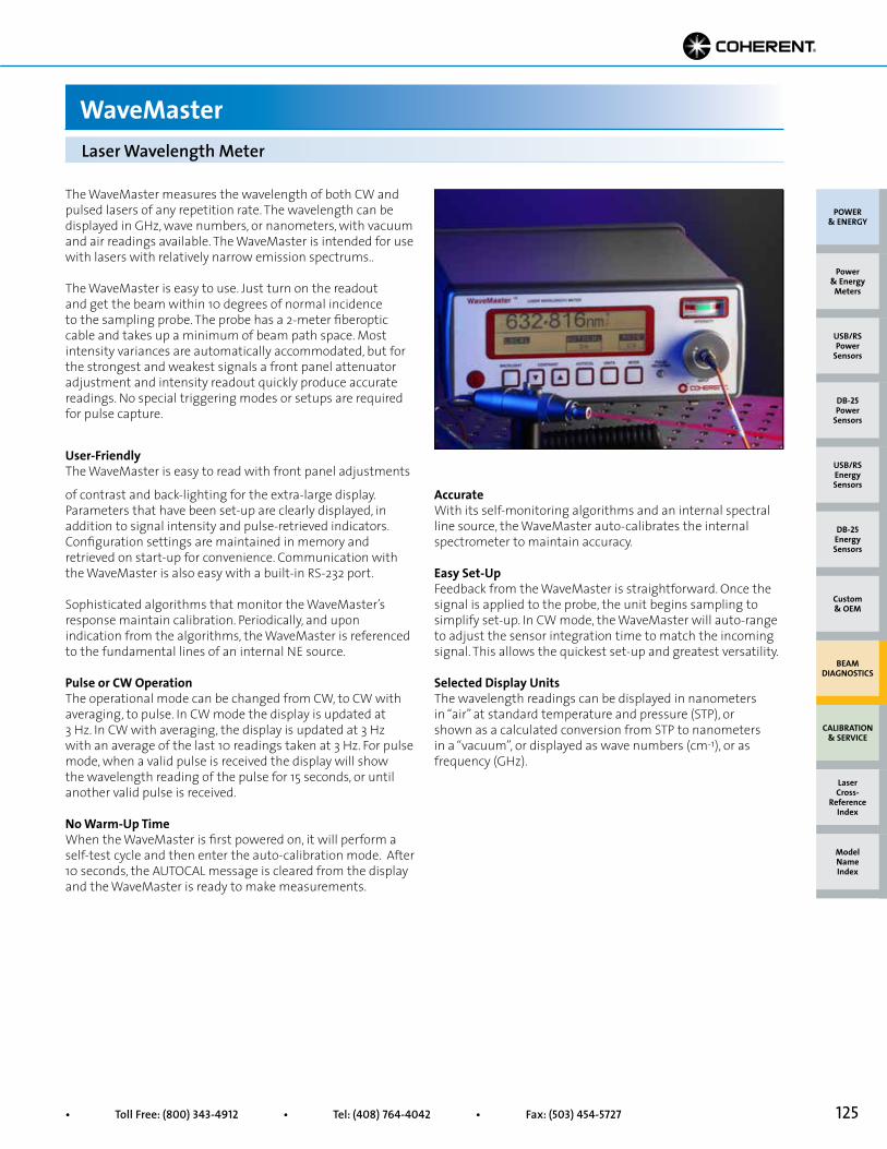
125• Toll Free: (800) 343-4912 • Tel: (408) 764-4042 • Fax: (503) 454-5727
AccurateWith its self-monitoring algorithms and an internal spectral line source, the WaveMaster auto-calibrates the internal spectrometer to maintain accuracy.
Easy Set-UpFeedback from the WaveMaster is straightforward. Once the signal is applied to the probe, the unit begins sampling to simplify set-up. In CW mode, the WaveMaster will auto-range to adjust the sensor integration time to match the incoming signal. This allows the quickest set-up and greatest versatility.
Selected Display UnitsThe wavelength readings can be displayed in nanometers in “air” at standard temperature and pressure (STP), or shown as a calculated conversion from STP to nanometers in a “vacuum”, or displayed as wave numbers (cm-1), or as frequency (GHz).
The WaveMaster measures the wavelength of both CW and pulsed lasers of any repetition rate. The wavelength can be displayed in GHz, wave numbers, or nanometers, with vacuum and air readings available. The WaveMaster is intended for use with lasers with relatively narrow emission spectrums..
The WaveMaster is easy to use. Just turn on the readout and get the beam within 10 degrees of normal incidence to the sampling probe. The probe has a 2-meter fiberoptic cable and takes up a minimum of beam path space. Most intensity variances are automatically accommodated, but for the strongest and weakest signals a front panel attenuator adjustment and intensity readout quickly produce accurate readings. No special triggering modes or setups are required for pulse capture.
User-FriendlyThe WaveMaster is easy to read with front panel adjustments
Laser Wavelength Meter
WaveMaster
of contrast and back-lighting for the extra-large display. Parameters that have been set-up are clearly displayed, in addition to signal intensity and pulse-retrieved indicators. Configuration settings are maintained in memory and retrieved on start-up for convenience. Communication with the WaveMaster is also easy with a built-in RS-232 port.
Sophisticated algorithms that monitor the WaveMaster’s response maintain calibration. Periodically, and upon indication from the algorithms, the WaveMaster is referenced to the fundamental lines of an internal NE source.
Pulse or CW OperationThe operational mode can be changed from CW, to CW with averaging, to pulse. In CW mode the display is updated at 3 Hz. In CW with averaging, the display is updated at 3 Hz with an average of the last 10 readings taken at 3 Hz. For pulse mode, when a valid pulse is received the display will show the wavelength reading of the pulse for 15 seconds, or until another valid pulse is received.
No Warm-Up TimeWhen the WaveMaster is first powered on, it will perform a self-test cycle and then enter the auto-calibration mode. After 10 seconds, the AUTOCAL message is cleared from the display and the WaveMaster is ready to make measurements.
POWER & ENERGY
Custom & OEM
BEAM DIAGNOSTICS
CALIBRATION & SERVICE
Power & Energy
Meters
Laser Cross-
Reference Index
Model Name Index
DB-25Energy Sensors
USB/RSEnergy Sensors
DB-25Power
Sensors
USB/RSPower
Sensors
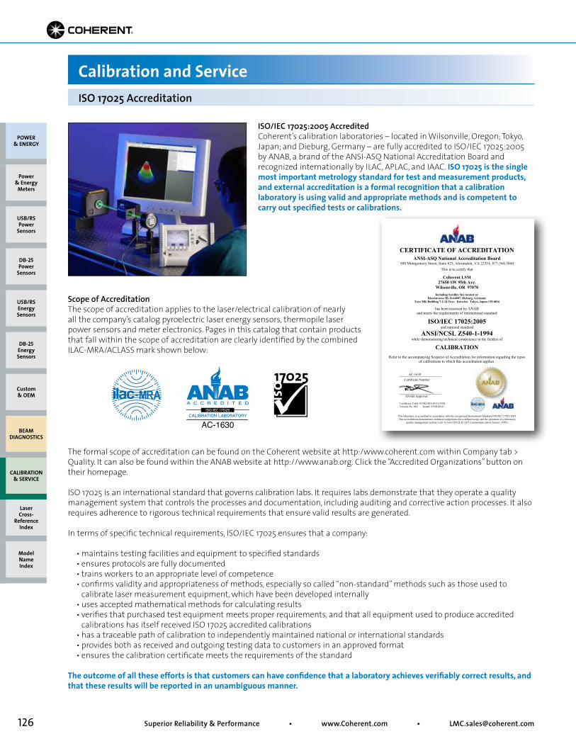
126 Superior Reliability & Performance • www.Coherent.com • [email protected]
ISO/IEC 17025:2005 AccreditedCoherent’s calibration laboratories – located in Wilsonville, Oregon; Tokyo, Japan; and Dieburg, Germany – are fully accredited to ISO/IEC 17025:2005 by ANAB, a brand of the ANSI-ASQ National Accreditation Board and recognized internationally by ILAC, APLAC, and IAAC. ISO 17025 is the single most important metrology standard for test and measurement products, and external accreditation is a formal recognition that a calibration laboratory is using valid and appropriate methods and is competent to carry out specified tests or calibrations.
Scope of AccreditationThe scope of accreditation applies to the laser/electrical calibration of nearly all the company’s catalog pyroelectric laser energy sensors, thermopile laser power sensors and meter electronics. Pages in this catalog that contain products that fall within the scope of accreditation are clearly identified by the combined ILAC-MRA/ACLASS mark shown below:
The formal scope of accreditation can be found on the Coherent website at http:/www.coherent.com within Company tab > Quality. It can also be found within the ANAB website at http://www.anab.org. Click the “Accredited Organizations” button on their homepage.
ISO 17025 is an international standard that governs calibration labs. It requires labs demonstrate that they operate a quality management system that controls the processes and documentation, including auditing and corrective action processes. It also requires adherence to rigorous technical requirements that ensure valid results are generated.
In terms of specific technical requirements, ISO/IEC 17025 ensures that a company:
• maintains testing facilities and equipment to specified standards • ensures protocols are fully documented • trains workers to an appropriate level of competence • confirms validity and appropriateness of methods, especially so called “non-standard” methods such as those used to calibrate laser measurement equipment, which have been developed internally • uses accepted mathematical methods for calculating results • verifies that purchased test equipment meets proper requirements, and that all equipment used to produce accredited calibrations has itself received ISO 17025 accredited calibrations • has a traceable path of calibration to independently maintained national or international standards • provides both as received and outgoing testing data to customers in an approved format • ensures the calibration certificate meets the requirements of the standard
The outcome of all these efforts is that customers can have confidence that a laboratory achieves verifiably correct results, and that these results will be reported in an unambiguous manner.
Calibration and ServiceISO 17025 Accreditation
CERTIFICATE OF ACCREDITATION
ANSI-ASQ National Accreditation Board 500 Montgomery Street, Suite 625, Alexandria, VA 22314, 877-344-3044
This is to certify that
Coherent LSM 27650 SW 95th Ave.
Wilsonville, OR 97070
Including Satellite Site located at: Dieselstrasse 5B, D-64807, Dieburg, Germany
Toyo MK Building 7-2-14 Toyo Koto-ku Tokyo, Japan 135-0016
has been assessed by ANAB and meets the requirements of international standard
ISO/IEC 17025:2005 and national standard
ANSI/NCSL Z540-1-1994 while demonstrating technical competence in the field(s) of
CALIBRATION
Refer to the accompanying Scope(s) of Accreditation for information regarding the types of calibrations to which this accreditation applies.
AC-1630
Certificate Number
ANAB Approval Certificate Valid: 03/08/2016-03/15/2018 Version No. 003 Issued: 03/08/2016
This laboratory is accredited in accordance with the recognized International Standard ISO/IEC 17025:2005. This accreditation demonstrates technical competence for a defined scope and the operation of a laboratory
quality management system (refer to joint ISO-ILAC-IAF Communiqué dated January 2009).
POWER & ENERGY
Custom & OEM
BEAM DIAGNOSTICS
CALIBRATION & SERVICE
Power & Energy
Meters
Laser Cross-
Reference Index
Model Name Index
DB-25Energy Sensors
USB/RSEnergy Sensors
DB-25Power
Sensors
USB/RSPower
Sensors
127• Toll Free: (800) 343-4912 • Tel: (408) 764-4042 • Fax: (503) 454-5727
Limited WarrantyCoherent, Inc., warrants to the original purchaser that its laser power and energy meters and sensors are free from defects in materials and workmanship and comply with all specifications, active at the time of purchase, for a period of twelve (12) months. Coherent, Inc., will, at its option, repair or replace any product or component found to be defective during the warranty period. This warranty applies only to the original purchaser and is not transferable.
Extended WarrantyCoherent, Inc., offers original purchasers of laser power and energy meters and sensors an extended twelve month warranty program, which includes all parts and labor. In order to qualify for this warranty, a Customer must return the Product to the Company for recalibration and recertification. The Company will recertify the Product, provide software upgrades, and perform any needed repairs, and recalibrate the Product, for a fixed service fee. If the Product fails and is returned to the Company within one year following the date of recalibration and recertification service, the Company will, at its option, repair or replace the Product or any component found to be defective.
Contact Coherent or visit www.Coherent.com/LMC for additional details and warranty limitations.
To prepare your instrument, meter or sensor for return to Coherent, attach a tag to the unit that includes the name and address of the owner, the contact individual, the serial number, and the RMA number you received from Customer Service.
Wrap the product with polyethylene sheeting or equivalent material. If the original packing material and carton are not available, obtain a corrugated cardboard shipping carton with inside dimensions that are at least 6 in. (15 cm) taller, wider, and deeper than the product. The shipping carton must be constructed of cardboard with a minimum 375 lbs. (170 kg) test strength. Cushion the instrument unit in the shipping carton, using 3 in. (7.5 cm) of packing material or urethane foam on all sides, top, bottom, and between the carton and the instrument or sensor. Seal the shipping carton with shipping tape or an industrial stapler.
Shipping addresses for our repair and calibration facilities are given below:
USACoherent Laser Measurement and Control Service CenterAttn: (your RMA number)27650 SW 95th AvenueWilsonville, OR 97070USA
Obtaining Warranty ServiceIn order to arrange for warranty service or annual recalibration, first contact your closest Coherent service center to obtain a Return Material Authorization (RMA) number.
USAPhone: 800 343 4912Fax: 503 454 5727E-mail: [email protected]
AsiaPhone: 813 5635 8680Fax: 813 5635 8701E-mail: [email protected]
EuropePhone: 49 6071 9680Fax: 49 6071 968499E-mail: [email protected]
Detailed instructions for preparing and shipping yourinstrument can be found below.
Calibration and ServiceWarranty and RMA Instructions
EuropeCoherent (Deutschland) GmbHDieselstr. 5bD-64807 DieburgGermany
AsiaCoherent JapanToyo MK Building7-2-14 ToyoKoto-Ku, Tokyo135-0016 Japan
Instructions for Returning Equipment for Service and Calibration
POWER & ENERGY
Custom & OEM
BEAM DIAGNOSTICS
CALIBRATION & SERVICE
Power & Energy
Meters
Laser Cross-
Reference Index
Model Name Index
DB-25Energy Sensors
USB/RSEnergy Sensors
DB-25Power
Sensors
USB/RSPower
Sensors
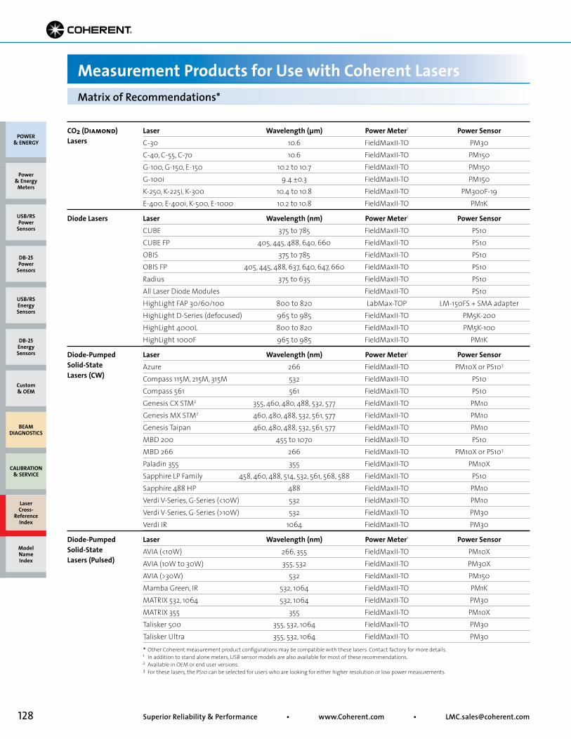
128 Superior Reliability & Performance • www.Coherent.com • [email protected]
Measurement Products for Use with Coherent LasersMatrix of Recommendations*
Laser Wavelength (µm) Power Meter1 Power SensorC-30 10.6 FieldMaxII-TO PM30C-40, C-55, C-70 10.6 FieldMaxII-TO PM150G-100, G-150, E-150 10.2 to 10.7 FieldMaxII-TO PM150G-100i 9.4 ±0.3 FieldMaxII-TO PM150K-250, K-225i, K-300 10.4 to 10.8 FieldMaxII-TO PM300F-19E-400, E-400i, K-500, E-1000 10.2 to 10.8 FieldMaxII-TO PM1K
CO2 (Diamond)Lasers
Laser Wavelength (nm) Power Meter1 Power SensorCUBE 375 to 785 FieldMaxII-TO PS10CUBE FP 405, 445, 488, 640, 660 FieldMaxII-TO PS10OBIS 375 to 785 FieldMaxII-TO PS10OBIS FP 405, 445, 488, 637, 640, 647, 660 FieldMaxII-TO PS10Radius 375 to 635 FieldMaxII-TO PS10All Laser Diode Modules FieldMaxII-TO PS10HighLight FAP 30/60/100 800 to 820 LabMax-TOP LM-150FS + SMA adapterHighLight D-Series (defocused) 965 to 985 FieldMaxII-TO PM5K-200HighLight 4000L 800 to 820 FieldMaxII-TO PM5K-100HighLight 1000F 965 to 985 FieldMaxII-TO PM1K
Diode Lasers
Laser Wavelength (nm) Power Meter1 Power SensorAVIA (<10W) 266, 355 FieldMaxII-TO PM10XAVIA (10W to 30W) 355, 532 FieldMaxII-TO PM30XAVIA (>30W) 532 FieldMaxII-TO PM150Mamba Green, IR 532, 1064 FieldMaxII-TO PM1K MATRIX 532, 1064 532, 1064 FieldMaxII-TO PM30MATRIX 355 355 FieldMaxII-TO PM10XTalisker 500 355, 532, 1064 FieldMaxII-TO PM30Talisker Ultra 355, 532, 1064 FieldMaxII-TO PM30
Laser Wavelength (nm) Power Meter1 Power SensorAzure 266 FieldMaxII-TO PM10X or PS103
Compass 115M, 215M, 315M 532 FieldMaxII-TO PS10Compass 561 561 FieldMaxII-TO PS10Genesis CX STM2 355, 460, 480, 488, 532, 577 FieldMaxII-TO PM10Genesis MX STM2 460, 480, 488, 532, 561, 577 FieldMaxII-TO PM10Genesis Taipan 460, 480, 488, 532, 561, 577 FieldMaxII-TO PM10MBD 200 455 to 1070 FieldMaxII-TO PS10 MBD 266 266 FieldMaxII-TO PM10X or PS103
Paladin 355 355 FieldMaxII-TO PM10XSapphire LP Family 458, 460, 488, 514, 532, 561, 568, 588 FieldMaxII-TO PS10Sapphire 488 HP 488 FieldMaxII-TO PM10Verdi V-Series, G-Series (<10W) 532 FieldMaxII-TO PM10Verdi V-Series, G-Series (>10W) 532 FieldMaxII-TO PM30Verdi IR 1064 FieldMaxII-TO PM30
Diode-Pumped Solid-State Lasers (CW)
Diode-Pumped Solid-State Lasers (Pulsed)
* Other Coherent measurement product configurations may be compatible with these lasers. Contact factory for more details. 1 In addition to stand alone meters, USB sensor models are also available for most of these recommendations.2 Available in OEM or end user versions. 3 For these lasers, the PS10 can be selected for users who are looking for either higher resolution or low power measurements.
POWER & ENERGY
Custom & OEM
BEAM DIAGNOSTICS
CALIBRATION & SERVICE
Power & Energy
Meters
Laser Cross-
Reference Index
Model Name Index
DB-25Energy Sensors
USB/RSEnergy Sensors
DB-25Power
Sensors
USB/RSPower
Sensors
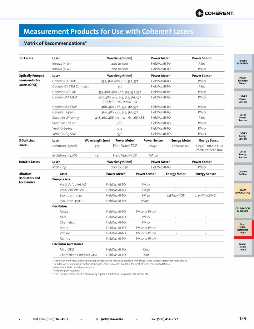
129• Toll Free: (800) 343-4912 • Tel: (408) 764-4042 • Fax: (503) 454-5727
Measurement Products for Use with Coherent LasersMatrix of Recommendations*
Laser Wavelength (nm) Power Meter1 Power SensorGenesis CX STM2 355, 460, 480, 488, 532, 577 FieldMaxII-TO PM10Genesis CX STM Compact 355 FieldMaxII-TO PS10Genesis CX SLM2 355, 460, 480, 488, 514, 532, 577 FieldMaxII-TO PM10Genesis MX MTM2 460, 480, 488, 514, 532, 561, 577 FieldMaxII-TO PM10 607, 639, 920, 1064, 1154Genesis MX STM2 460, 480, 488, 532, 561, 577 FieldMaxII-TO PM10Genesis Taipan 460, 480, 488, 532, 561, 577 FieldMaxII-TO PM10Sapphire LP Family 458, 460, 488, 514, 532, 561, 568, 588 FieldMaxII-TO PS10Sapphire 488 HP 488 FieldMaxII-TO PM10Verdi G-Series 532 FieldMaxII-TO PM10Verdi G2/G5 SLM 532 FieldMaxII-TO PM10
Optically Pumped Semiconductor Lasers (OPSL)
Laser Wavelength (nm) Power Meter1 Power Sensor Energy Meter Energy SensorEvolution (<30W) 527 FieldMaxII-TOP PM30 LabMax-TOP J-25MT-10KHZ plus medium heat sinkEvolution (>30W) 527 FieldMaxII-TOP PM150
Q-Switched Lasers
Laser Power Meter1 Power Sensor Energy Meter Energy SensorPump Lasers Verdi V2, V5, V6, V8 FieldMaxII-TO PM10 - - Verdi V10, V12, V18 FieldMaxII-TO PM30 - - Evolution-15/30 FieldMaxII-TO PM30 LabMax-TOP J-25MT-10KHZ3
Evolution-45/HE FieldMaxII-TO PM150 - - Oscillators Micra FieldMaxII-TO PM10 or PS104 - - Mira FieldMaxII-TO PM10 - - Chameleon FieldMaxII-TO PM10 - - Vitara FieldMaxII-TO PM10 or PS104 - - Vitesse FieldMaxII-TO PM10 or PS104 - - Mantis FieldMaxII-TO PM10 or PS104 - -Oscillator Accessories Mira-OPO FieldMaxII-TO PS10 - - Chameleon Compact OPO FieldMaxII-TO PS10 - -
Ultrafast Oscillators and Accessories
* Other Coherent measurement product configurations may be compatible with these lasers. Contact factory for more details. 1 In addition to stand alone meters, USB sensor models are also available for most of these recommendations. 2 Available in OEM or end user versions. 3 With medium heat sink.4 The PS10 is recommended when making higher resolution or low power measurements.
Laser Wavelength (nm) Power Meter1 Power SensorInnova (<1W) 200 to 1100 FieldMaxII-TO PS10Innova (>1W) 200 to 1100 FieldMaxII-TO PM10
Ion Lasers
Laser Wavelength (nm) Power Meter1 Power SensorMBR Ring 700 to 1030 FieldMaxII-TO PM10
Tunable Lasers
POWER & ENERGY
Custom & OEM
BEAM DIAGNOSTICS
CALIBRATION & SERVICE
Power & Energy
Meters
Laser Cross-
Reference Index
Model Name Index
DB-25Energy Sensors
USB/RSEnergy Sensors
DB-25Power
Sensors
USB/RSPower
Sensors
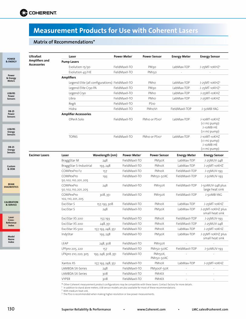
130 Superior Reliability & Performance • www.Coherent.com • [email protected]
Laser Wavelength (nm) Power Meter1 Power Sensor Energy Meter Energy SensorBraggStar M 248 FieldMaxII-TO PM30X LabMax-TOP J-25MUV-248BraggStar S-Industrial 193, 248 FieldMaxII-TO PM10X LabMax-TOP J-25MT-10KHZCOMPexPro F2 157 FieldMaxII-TO PM10X FieldMaxII-TOP J-25MUV-193COMPexPro 193 FieldMaxII-TO PM150-50XC FieldMaxII-TOP J-50MUV-193 50, 102, 110, 201, 205 COMPexPro 248 FieldMaxII-TO PM150X FieldMaxII-TOP J-50MUV-248 plus 50, 102, 110, 201, 205 large heat sinkCOMPexPro 308, 351 FieldMaxII-TO PM150X FieldMaxII-TOP J-50MB-YAG 102, 110, 201, 205ExciStar S 157, 193, 308 FieldMaxII-TO PM10X LabMax-TOP J-25MT-10KHZExciStar S 248 FieldMaxII-TO PM30X LabMax-TOP J-25MT-10KHZ plus small heat sinkExciStar XS 200 157, 193 FieldMaxII-TO PM10X FieldMaxII-TOP J-25MUV-193ExciStar XS 200 248, 351 FieldMaxII-TO PM10X FieldMaxII-TOP J-25MUV-248ExciStar XS 500 157, 193, 248, 351 FieldMaxII-TO PM10X LabMax-TOP J-25MT-10KHZIndyStar 193, 248 FieldMaxII-TO PM30X LabMax-TOP J-25MT-10KHZ plus small heat sinkLEAP 248, 308 FieldMaxII-TO PM150X - -LPFpro 205, 220 157 FieldMaxII-TO PM150-50XC FieldMaxII-TOP J-50MUV-193LPXpro 210, 220, 305 193, 248, 308, 351 FieldMaxII-TO PM150X, - - PM150-50XC Xantos XS 157, 193, 248, 351 FieldMaxII-TO PM10X LabMax-TOP J-25MT-10KHZLAMBDA SX-Series 248 FieldMaxII-TO PM300F-50X - -LAMBDA SX-Series 308 FieldMaxII-TO PM1KX - -VYPER 308 FieldMaxII-TO PM1KX - -
Excimer Lasers
Measurement Products for Use with Coherent LasersMatrix of Recommendations*
Laser Power Meter1 Power Sensor Energy Meter Energy SensorPump Lasers Evolution-15/30 FieldMaxII-TO PM30 LabMax-TOP J-25MT-10KHZ2
Evolution-45/HE FieldMaxII-TO PM150 - - Amplifiers Legend Elite (all configurations) FieldMaxII-TO PM10 LabMax-TOP J-25MT-10KHZ2
Legend Elite Cryo PA FieldMaxII-TO PM30 LabMax-TOP J-25MT-10KHZ2
Legend Cryo FieldMaxII-TO PM10 LabMax-TOP J-25MT-10KHZ Libra FieldMaxII-TO PM10 LabMax-TOP J-25MT-10KHZ RegA FieldMaxII-TO PS10 Hidra FieldMaxII-TO PM10V1 FieldMaxII-TOP J-50MB-YAGAmplifier Accessories OPerA Solo FieldMaxII-TO PM10 or PS103 LabMax-TOP J-10MT-10KHZ (<1 mJ pump) J-10MB-HE (>1 mJ pump) TOPAS FieldMaxII-TO PM10 or PS103 LabMax-TOP J-10MT-10KHZ (<1 mJ pump) J-10MB-HE (>1 mJ pump)
Ultrafast Amplifiers and Accessories
* Other Coherent measurement product configurations may be compatible with these lasers. Contact factory for more details. 1 In addition to stand alone meters, USB sensor models are also available for most of these recommendations.2 With medium heat sink.3 The PS10 is recommended when making higher resolution or low power measurements.
POWER & ENERGY
Custom & OEM
BEAM DIAGNOSTICS
CALIBRATION & SERVICE
Power & Energy
Meters
Laser Cross-
Reference Index
Model Name Index
DB-25Energy Sensors
USB/RSEnergy Sensors
DB-25Power
Sensors
USB/RSPower
Sensors
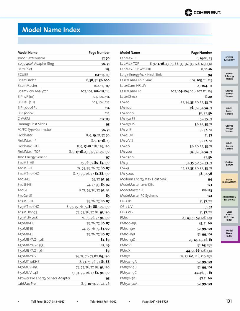
131• Toll Free: (800) 343-4912 • Tel: (408) 764-4042 • Fax: (503) 454-5727
Model Name Page Number1000:1 Attenuator 57, 701.035-40M Adapter Ring 50, 71Barrel Set 113BCUBE 112-113, 117BeamFinder 8, 38, 52, 56, 100BeamMaster 102, 115-117BeamView Analyzer 102, 103, 106-111, 114BIP-12F (1:1) 103, 104, 114BIP-12F (2:1) 103, 104, 114BIP-5000SPL 114BIP-5000Z 114C-VARM 112-113Damage Test Slides 95FC/PC-Type Connector 50, 71FieldMate 8, 9, 19, 21, 57, 70FieldMaxII-P 8, 9, 17-18, 73FieldMaxII-TO 8, 9, 17-18, 128, 129, 130FieldMaxII-TOP 8, 9, 17-18, 23, 73, 97, 129, 130J100 Energy Sensor 97J-10MB-HE 75, 76, 77, 80, 87, 130J-10MB-LE 73, 74, 75, 76, 77, 80, 87J-10MT-10KHZ 8, 73, 75, 76, 77, 81, 88, 130J-10SI-LE 74, 77, 92, 93J-10SI-HE 74, 77, 93, 85, 92J-10GE 8, 73, 74, 76, 77, 92, 93J-10Ge-LE 85J-25MB-HE 75, 76, 77, 80, 87J-25MT-10KHZ 8, 73, 75, 76, 77, 81, 88, 129, 130J-25MUV-193 74, 75, 76, 77, 84, 91, 130J-25MUV-248 74, 75, 76, 77, 91, 130J-50MB-HE 75, 76, 77, 80, 87J-50MB-IR 74, 75, 76, 77, 83, 90J-50MB-LE 75, 76, 77, 80, 87J-50MB-YAG-1528 82, 89J-50MB-YAG-1535 82, 89J-50MB-YAG-1561 89J-50MB-YAG 74, 75, 76, 77, 82, 89, 130J-50MT-10KHZ 8, 73, 75, 76, 77, 81, 88J-50MUV-193 74, 75, 76, 77, 84, 91, 130J-50MUV-248 73, 74, 75, 76, 77, 84, 91, 130J-Power Pro Energy Sensor Adapter 95LabMax-Pro 8, 9, 10-13, 21, 24, 26
Model Name Page NumberLabMax-TO 8, 14-16, 23LabMax-TOP 8, 9, 14-16, 23, 73, 88, 93, 92, 97, 128, 129, 130LabMax-TOP w/GPIB 8, 14-16Large EnergyMax Heat Sink 94LaserCam-HR-InGaAs 103, 105, 111, 113LaserCam-HR-UV 103, 104, 111LaserCam-HR 102, 103-104, 106, 107, 111, 114LaserCheck 8, 20LM-10 32, 34, 35, 50, 52, 53, 71LM-100 36, 50, 52, 54, 71LM-1000 38, 52, 56LM-150 FS 52, 55, 71LM-150 LS 36, 52, 55, 71LM-2 IR 51, 57, 70LM-2 UV 51, 57LM-2 VIS 51, 57, 70LM-20 36, 50, 52, 55, 71LM-200 37, 50, 52, 54, 71LM-2500 52, 56LM-3 32, 35, 50, 52, 53, 71LM-45 14, 32, 35, 50, 52, 53, 71LM-5000 38, 52, 56Medium EnergyMax Heat Sink 94ModeMaster Lens Kits 123ModeMaster PC 118-123ModeMaster PC Systems 122OP-2 IR 51, 57, 70OP-2 UV 51, 57OP-2 VIS 51, 57, 70PM10 23, 43, 51, 59, 128, 129PM100-19C 45, 51, 60PM10-19A 52, 99, 101PM10-19B 52, 99, 101PM10-19C 23, 45, 45, 46, 61PM10V1 52, 65, 130PM10X 44, 51, 66, 128, 130PM150 23, 51, 60, 128, 129, 130PM150-19A 52, 99, 101PM150-19B 52, 99, 101PM150-19C 45, 46, 51, 61PM150-50 47 51, 60PM150-50A 52, 99, 101
Model Name Index
POWER & ENERGY
Custom & OEM
BEAM DIAGNOSTICS
CALIBRATION & SERVICE
Power & Energy
Meters
Laser Cross-
Reference Index
Model Name Index
DB-25Energy Sensors
USB/RSEnergy Sensors
DB-25Power
Sensors
USB/RSPower
Sensors

132 Superior Reliability & Performance • www.Coherent.com • [email protected]
Model Name Index
Model Name Page NumberPM150-50B 52, 100, 101PM150-50C 23, 45, 46, 51, 61PM150-50XB 52, 100, 101PM150-50XC 23, 49, 51, 67, 130PM150X 51, 67, 130PM1K 48, 52, 63, 128PM1K-100 52, 64PM1K-36B 52, 100, 101PM1K-36C 47PM1KX 67, 130PM1KX-100 49, 69PM2 43, 51 59PM200F-19 51, 62PM200F-50 51, 62PM200F-50X 51, 68PM2X 44, 51, 66PM3 40, 51, 58PM30 43, 51, 59, 128, 129, 130PM300 51, 61PM300F-19 51, 62, 128PM300F-50 51, 62PM300F-50X 51, 68, 130PM30V1 52, 65PM30X 44, 51, 66, 128, 130PM3K 48, 52, 63PM3K-100 52, 64PM3Q 40, 51, 58PM5K 48, 52, 63PM5K-100 49, 52, 64, 128PM5K-200 52, 64, 128Posts and Stands 71, 94Power Supplies 21PowerMax-Pro 4, 5, 7, 8, 9, 10, 11, 13, 24-31, 95PS10 23, 39, 40, 50, 51, 58, 71, 128, 129, 130PS10Q 23, 39, 51, 58PS19 23, 39, 40, 51, 58PS19Q 23, 39, 51, 58PS-FC-Type Connector 50, 71PS-SMA-Type Connector 50, 71Rechargeable Batteries 21Small EnergyMax Heat Sink 94SMA-Type Connector 50, 71
Model Name Page NumberSoft Carrying Cases 16, 18, 21Thermal SmartSensor Adapter 8, 70UV-BCUBE 112-113UV/VIS 34, 41, 42, 50UV C-VARM 112-113VARM 112-113WaveMaster 102, 124-125Wand UV/VIS 41Wand UV/VIS Adapters 50
POWER & ENERGY
Custom & OEM
BEAM DIAGNOSTICS
CALIBRATION & SERVICE
Power & Energy
Meters
Laser Cross-
Reference Index
Model Name Index
DB-25Energy Sensors
USB/RSEnergy Sensors
DB-25Power
Sensors
USB/RSPower
Sensors

Notes
133• Toll Free: (800) 343-4912 • Tel: (408) 764-4042 • Fax: (503) 454-5727


OrderingWe are pleased to accept orders online at www.Coherent.com, or by phone, fax, e-mail or mail. When confirming an order that has been placed, please indicate “confirming” on the order.
PricingPrices are FOB Portland, OR, and do not include freight, duty or any applicable taxes.
Please consult your local Sales Office or Distributor for export prices.
Terms of PaymentAcceptable terms of payment for domestic orders include cash with order, major credit card, C.O.D. or Net 30 with prior approval of credit.
Export terms are strictly letter of credit, cash in advance or major credit card.
ShippingShipment means are at the discretion of Coherent, but we will attempt to meet your special requests. We do not take responsibility for any delays or damage caused by the shipper.
ReturnsReturns are accepted only after a return authorization number has been obtained from Coherent, and credit will be allowed for items returned under authorization in good condition.
Order CancellationCancellation of orders will incur a termination charge of not less than 10% of the order value, and Coherent reserves the right to charge for all costs incurred in support of any cancelled order.
WarrantyGoods are warranted to be free from defects and to work in the manner specified for a period of 12 months from date of shipment. See page 127 for further warranty details.
SpecificationsSpecifications are current at the time of publication, but Coherent reserves the right to change these specifications at any time. Refer to www.Coherent.com for the most current product specifications.
Terms and Conditions of SaleTerms and Conditions of Sale are specific to each country in which Coherent operates. They are supplied with all quotations and invoices and can be sent by fax or mail on request. Nothing in the foregoing statements modifies the Terms and Conditions in effect for each country of operation.
RoHS ComplianceThe majority of products in this catalog are RoHS compliant. For more information on specific products, please contact a Coherent Sales Office or Representative.
Doing Business with Coherent
135• Toll Free: (800) 343-4912 • Tel: (408) 764-4042 • Fax: (503) 454-5727
Contact Us by Phone
Coherent, Inc.(800) 343-4912 or (408) 764-4042
Benelux: +31 (30) 280 6060
China: +86 (10) 8215 3600
France: +33 (0)1 8038 1000
Germany/Austria/Switzerland: +49 (6071) 968 333
Italy: +39 (02) 31 03 951
Japan: +81 (3) 5635 8680
Korea: +82 (2) 460 7900
Taiwan: +886 (3) 505 2900
United Kingdom/Ireland: +44 (0) 1353 658833
Contact Us by Email
Laser Products: [email protected]
Laser Measurement: [email protected]
Service: [email protected]
How to Contact Us
All Coherent product names are trademarks of Coherent, Inc.*All products indicated by an asterisk are registered trademarks of their respective companies.136
Visit the Coherent Websitefor more information about how Coherent can
enable your laser measurement application.
Use the Product and Application Finders belowto quickly get more helpful details.
Comprehensive Meter and Sensor Finder
Applications Software and Drivers
Frequently Asked Questions
Enhanced Application Finder
Brochures, Tech Notes, Technical Illustrations, Videos, Data Sheets
www.Coherent.com/LMC
Printed in the U.S.A. MC-002-15-0M0816Copyright © 2016 Coherent, Inc.
Coherent, Inc., Corporate Headquarters5100 Patrick Henry DriveSanta Clara, CA 95054
United States Coherent, Inc., Portland27650 SW 95th AvenueWilsonville, OR 97070United StatesToll Free: 1-800-343-4912Tel: (408) 764-4042Fax: (503) 454-5727www.Coherent.com
ChinaCoherent Inc., BeijingRoom 1006-1009, Raycom Info Park Tower B, No. 2, Kexueyuan South RoadHaidian District Beijing, 100190, ChinaTel: 86-10-8215-3600Hotline Mainland China Only: +86-4006100209www.Coherent.com.cn
FranceCoherent FranceParc Technopolis3, Avenue du CanadaBâtiment Zeta91978 Courtaboeuf cedexFranceTel: +33-1-80-38-10-00Fax: +33-1-80-38-10-01www.Coherent.fr
Germany/Austria/Switzerland/DenmarkCoherent GmbHDieselstraße 5bD-64807 DieburgGermanyTel: +49-6071-968-333Fax: +49-6071-968-499www.Coherent.de
ItalyCoherent ItaliaVia Borgese, 14Milano, 20154ItalyTel: +39-02-31-03-951Fax: +39-02-31-03-95-55www.Coherent.it
JapanCoherent Japan, Inc. Toyo MK Building7-2-14 ToyoKoto-ku, Tokyo 135-0016JapanTel: +81 3-5635-8680Fax: +81 3-5635-8701www.Coherent.co.jp
KoreaNo. 101, Eagle Town278-20, 3 dongSeongsu 2 gaSeongdong-gu, Seoul133-832, South KoreaTel: +82 2 460 7900www.Coherent.com
NetherlandsCoherent B.V.Smart Business Park Kanaalweg 18A3526 KL UtrechtNetherlandsTel: +31-30-280-6060Fax: +31-30-280-6077www.Coherent.nl
TaiwanCoherent Taiwan2F-5, No. 38. Taiyuan St.Zubei City, Hsinchu County 30265TaiwanTel: +886-3-505-2900www.Coherent.com
United Kingdom/IrelandCoherent UK Ltd.St Thomas’ PlaceCambridgeshire Business ParkElyCB7 4EXEnglandTel: +44-1353-658-833Fax: +44-1353-659-110www.Coherent.com