laser micromachining of tin coatings with variable …laser micromachining of tin coatings with...
TRANSCRIPT

Laser micromachining of TiN coatings with variable pulse
durations and shapes in ns regime
Ali Gökhan Demir1*, Krste Pangovski2, William O’Neill2, Barbara Previtali1
1Department of Mechanical Engineering, Politecnico di Milano, Via La Masa 1, 20156 Milan, Italy
2Institute for Manufacturing, University of Cambridge, 17 Charles Babbage Road, Cambridge, CB3
0FS, United Kingdom
*Corresponding author: [email protected]

1
Laser micromachining of TiN coatings with variable pulse durations and shapes in ns regime
Ali Gökhan Demir1*, Krste Pangovski2, William O’Neill2, Barbara Previtali1
1Department of Mechanical Engineering, Politecnico di Milano, Via La Masa 1, 20156 Milan, Italy
2Institute for Manufacturing, University of Cambridge, 17 Charles Babbage Road, Cambridge, CB3
0FS, United Kingdom
*Corresponding author: [email protected]
Abstract
The micro-structuring of thin surface coatings has become increasingly popular following the discovery
of improved performance, especially in terms of the resulting tribological properties. The direct writing
of microstructures via laser ablation offers flexibility, extending the applicability of micro-structuring to
various materials and machined geometries. However, the laser ablation of coatings requires better
comprehension to provide sufficient machining quality with improved productivity to render such
processes more viable for industrial applications. This paper presents the processing conditions for the
ablation of approximately 4-µm-thick coatings of TiN in the ns pulse regime, which is generally
characterised by higher productivity with low machining quality. A range of pulse durations between 12
ns and 200 ns was employed. The effect of pulse duration on ablation threshold fluence and irradiance
was investigated. The pulse shape was decomposed into peak and tail regions to investigate their
respective effects on the ablation process. The opportune regulation of pulse properties allowed for the
maintenance of high productivity and high-quality laser micromachining under delicate processing
conditions, in the case of ceramic TiN surface coatings with limited thickness.
Keywords: TiN; Surface micro-structuring; Laser surface texturing; Laser ablation; Laser percussion
drilling

2
1. Introduction
Ceramic surface coatings are extensively applied for various purposes, encompassing mechanical,
biomedical, and electronic applications. Ceramic surface coatings applied as superficial layers are of
interest for improving the performance of components because of their superior properties in terms of
mechanical, thermal and chemical stability. In particular, TiN coatings are extensively used in industrial
applications, such as cutting tools, dies and moulds, biomedical implants, and components used in food
industries, as well as for decorative purposes [1-3]. Recently, the surface structuring and machining of
these coatings has gained increasing attention. Because the coating layer is limited to a very small
thickness (a few µm), the machining conditions required can be fulfilled by micro-processing techniques.
The high hardness and fragile nature of ceramic coatings should also be considered during process
selection. The traditional chip removal processes are not adaptable to surface structuring of ceramic
coatings. Chemical etching processes are applicable, although the corrosion stability of the material can
limit their feasibility. However, the direct writing of desired patterns with laser micromachining provides
a flexible solution with high machining resolution, flexibility in machined geometries, and reduced lead
times between design and production, because the process does not necessarily require dies or masks.
The laser micromachining applications of TiN coatings include microdrilling for the enhanced fixation
of dental implants [4], surface micromachining of sensors and actuators in MEMS [5], and surface
texturing for the improved tribological performance of mechanical components [6], among others. In
addition to surface patterning, laser micromachining has also been used to remove TiN layers from
cutting tools [7].
The processing quality of the laser micromachining of ceramic coatings, as in the case of all laser ablation
based process, mainly depends on the laser wavelength (λ) and pulse duration (τ). These two factors
combined determine the interaction between the laser and matter. The laser wavelength is the principal

3
parameter in determining the absorption of laser energy by the machined material, although absorption
is a dynamic phenomenon that depends on time-dependant physical parameters, such as temperature.
Thus, absorption is likely to vary even within the duration of a single laser pulse. Moreover, shorter
wavelengths can provide higher machining resolution due to enhanced laser beam focusability. The pulse
duration is generally categorised as long pulses (ms, µs), short pulses (ns), and ultrashort pulses (ps, fs).
Ultrashort pulses provide better machining quality, because the interaction time between the material and
the light is sufficiently short to prevent electron-lattice coupling [8]. The process depends on optical
penetration, and the ablation conditions yield direct removal from solid. With increasing pulse duration,
electron-lattice coupling is fulfilled, and the heat penetrates into the bulk material. Heat diffusion within
the bulk material causes temperature gradients, which lead to the vaporisation or melting of different
material fractions. Common defects in laser micromachining, namely, heat-affected zones, dross and
recast, result from this effect. Although longer pulses are characterised by such defects, laser sources
operating with longer pulses are widely used at the industrial scale with large pulse energies and high
pulse repetition rates, which provide faster machining conditions.
The interactions between laser beams and TiN coatings have been investigated in the literature based on
different combinations of wavelength and pulse duration. The effect of µs pulses generated with a CO2
laser on TiN coatings demonstrated a melt dominant material removal mechanism [9-11], although the
resulting machining quality was far from that required for high-precision micromachining. It was
reported that ns pulses generated with KrCl (λ=222 nm) [10] and XeCl (λ=308 nm) [11] excimer lasers
generated significantly smaller melt fractions generated in comparison to µs pulses. Kononenko et al.
[12] compared the effect of ns and ps pulse durations using combinations of UV (270 nm), visible (539
nm), and IR (1078 nm) wavelengths. The authors reported no significant change in ablation rate as a
function of wavelength used due to the constant optical penetration depth in the wavelengths employed.
The same observation was presented for the pulse durations employed (150 ps – 9 ns); however, the
4
authors reported increased heat affected zones with ns pulses due to increased heat penetration depth. In
another work, the micromachining of TiN with fs pulses was reported to yield melt free, vaporisation
dominant ablation conditions with high machining quality [13].
Although wavelength and pulse duration are the major factors that determine micromachining quality,
other parameters, such as the beam quality factor (M2), transverse electromagnetic mode (TEM), and
pulse-to-pulse energy stability, are of high importance for high-precision and robust micromachining
operations. Pulse shape is one of the less explored parameters with respect to micromachining quality.
For a preliminary distinction, pulse duration is adequate; however, to better comprehend the ablation
phenomenon, pulse duration alone is not satisfactory. The same amount of energy can be delivered with
the same pulse duration when delivered according to different temporal shapes. Because every material-
laser beam couple constitutes different conditions, the usual conventions regarding the pulse duration,
such as full-width at half-maximum (FWHM), or the pulse intensity, such as fluence and irradiance, can
create ambiguities during comparison. The distinctions between the forms are more crucial under
conditions in which the pulse duration is significantly higher than the lattice cooling temperature of the
material (which is on the order of ps), for example, in the case of ns pulses. Changes in the nature of
machining occur when using ns pulses due to fast ascending peaks; more specifically, Si can be machined
with 1064 nm wavelength laser, to which the material is transparent at room temperature [14]. With the
development of new generation of solid state lasers that possess pulse form and duration
programmability, laser micromachining with ns pulses has attained increased flexibility during operation
and a larger margin of quality improvement, which are critically important factors for industrial scale
production.
The present work presents the laser characterisation of micromachining of TiN coatings on AISI M2 tool
steel with a variety of pulse durations and shapes in the ns regime using a master oscillator pulse amplifier

5
(MOPA) fibre laser. The pulse durations and shapes were selected and analysed within the 12 – 200 ns
range. Single- and multiple-pulse ablation conditions were investigated to better comprehend the roles
of the pulse components, including the duration, energy, and peak power. In particular, different ablation
conditions within the ns regime were investigated in single-pulse ablation, where a quantitative analysis
of the influence of pulse duration on ablation fluence and irradiance thresholds was attempted. In a large
pulse duration range using singular intensity parameters, such as the threshold fluence or irradiance was
observed to be inadequate, because inverse behaviour was observed as a function of pulse duration in
these two parameters. Accordingly, the pulse shapes were decomposed to explain the role of the primary
peak and tail. A regression model was fitted to better explain the ablation phenomenon using the
decomposition parameters. Under multiple-pulse conditions, the percussion drilling of the coating was
investigated as a function of the pulse shape and duration, energy and number of pulses emitted. The
effects on hole geometry and quality were discussed. The results were interpreted both from a physical
point of view to explain different machining conditions, as well as to indicate the preferential conditions
for better quality and higher productivity.
2. Materials and methods
The substrate was quenched and tempered 12-mm-thick AISI M2 tool steel with a ground surface finish.
The TiN coating was deposited by cathodic arc physical vapour deposition (Lafer SpA, Piacenza, Italy).
The coating was deposited at 450°C for a total duration of 1 h 45 min. This substrate was matched to the
coating, because the combination suitably represents coated deformation and cutting tools. The measured
coating thickness was estimated as 3.91 ± 0.09 µm, whereas the average coating roughness was Ra= 0.80
± 0.06 μm perpendicular to the grinding direction. The physical properties of the coating and substrate
materials are listed in Table I. An active fibre laser with a master oscillator pulse amplifier (MOPA)
architecture and pulse-tuning capability was employed for the study (SPI G3 20P-HS, Southampton,

6
UK). The laser source was programmable to produce different durations varying between 9 ns – 200 ns,
with a maximum pulse energy of 0.8 mJ available for the longest pulse duration. Beam positioning was
achieved via a scanner head (Nutfield XLR8-15-1064, Hudson, NH, USA), which housed a 125-mm
focal lens. The system specifications are detailed in Table II.
The pulses generated with the present laser source were characterised by fast ascending peaks and tails
that decayed at relatively slower rates. Decreasing the pulse duration did not change the primary peak
but shortened the decay tail. For this study, pulse durations of 12 ns, 30 ns, 65 ns, 100 ns, 150 ns, and
200 ns were chosen. Figure 1 depicts the pulse shapes of the chosen pulse durations with varying pulse
duration and similar peak powers. Bell-shaped symmetry around the peak power value is present only
with shorter pulses of 12 ns and 30 ns. Hence, for a given pulse duration, the pulse energy variation
changes the pulse shape for longer pulses. Between 65-200 ns, the pulse peak shape flattens as the energy
is reduced; in contrast, with 12 ns and 30 ns pulses, the symmetry is maintained.
The experimental work consisted of two phases. In the initial phase, the single-pulse ablation of TiN
coatings was investigated as a function of fluence (F [J/cm2]), irradiance (I [MW/cm2]), and pulse
duration (τ [ns]), with the first two defined as:
F=2Ep/(πws2) Eq. (1)
I=2Ppeak/(πws2) Eq. (2)
where Ep is the pulse energy, Ppeak is the pulse peak power, ws is the laser spot radius at the material
surface. All experiments were carried out with the focal plane on the surface, thus the laser spot radius,
ws, was equal to the radius at the focal plane (ws=w0), calculated as:
w0=λM2f/(πwc) Eq. (3)
7
where λ is the laser wavelength, M2 is the beam quality factor, f is the focal length of the focusing lens,
and wc is the collimated beam radius projected on the focusing lens [16].
The ablated area diameter was measured from optical microscopy images (Olympus BX51, Melville,
NY, USA). SEM (Zeiss EVO-50, Oberkochen, Germany) images were collected in secondary electron
and back scattered emission modes to better define the ablation morphology. Morphological analysis was
carried out on these images to reveal the effect of peak power, energy, and pulse duration on the ablation
mechanisms and quality. The effect of pulse duration was compared between machining conditions,
characterised by similar energy and similar peak power levels.
To quantify the effects of the pulse energy and peak power separately, the threshold fluence and
irradiance values were calculated for different pulse durations. The threshold fluence and irradiance were
calculated according to the model proposed by Liu [20]. The threshold fluence was calculated as:
D2=2w02ln(F/Fth) Eq. (4)
while the threshold irradiance was calculated as:
D2=2w02ln(I/Ith) Eq. (5)
where D is the ablated zone diameter, and Fth and Ith are the ablation threshold fluence and irradiance,
respectively. Thus far, the model proves to be adaptable to shorter ps, and fs pulses, which provide
thermal effect-free ablation conditions, thus free of melt generation. Therefore, the measured area reflects
the effective beam size capable of ablating the material surface. Provided that the ablated region is free
of melt and can be easily defined, the model can also be applied to longer pulse durations. The model
assumes a Gaussian energy distribution of the laser beam. Although the laser sources used in this work
had a beam quality factor of M2≤2, the beam shape was characterised by a single sharp peak at the centre,
suitable for being estimated as a near-Gaussian beam [14]. The ablation threshold fluence and irradiation

8
were calculated using a nonlinear regression method by means of statistical software (Minitab). The
method uses an iterative algorithm (Gauss-Newton) to match the unknowns of the non-linear regression
equation starting from set values and then diverges to the best fit. The known parameters of the non-
linear regression are the measured ablated area diameters, D, and the pulse energy, Ep, in the case of
threshold fluence (Ppeak in the case of threshold irradiance). The unknowns that are estimated through the
algorithm are the beam radius at the focal position, w0, and the ablation threshold fluence, Fth (or
threshold irradiance Ith). It is preferable to set both w0 and Fth (or Ith in the case of threshold irradiance)
as the unknowns of the equation, because slight variations of the spot radius are expected during
experimentation. In this case, the advantage is that the statistical confidence intervals for the mean are
calculated to the equation unknowns, providing a direct value of the error developed during the
calculation of the threshold fluence and irradiation values. The forms of the equations with the two
unknowns as used here are given below:
Eq.
(6)
Eq. (7)
The ablation threshold model has been widely used since its introduction. It is an effective model for
distinguishing the ablation characteristics of different materials for fixed pulse durations. However, over
large ranges in pulse durations, especially when ns pulses are concerned, the model can generate
ambiguities. Due to thermal interaction, the pulse shape becomes critically important, because it
determines the rate of energy deposition to the material. To introduce the various effects of pulse energy
th
p
F
w
E
wD202
02
2
ln2
th
peak
I
w
P
wD2
020
2
2
ln2
9
and peak power into a single model, a pulse decomposition approach was introduced. A statistical
regression model was fitted over the experimental data to quantify the effects of the separate pulse
components.
In the second phase of the experimental work, a multiple-pulse study was performed. The number of
pulse durations used was reduced to three values, namely, 12 ns, 100 ns, and 200 ns. The pulse number
was varied to drill into the coating and then into the substrate, to reveal the effect of changes in material
response when switching from the coating material to the substrate. Optical microscopy and SEM images
were collected to investigate the machining behaviour and measure the diameter of the hole drilled. A
white light interferometer system (Veeco NT3300, Plainview, NY, USA) was used to measure the depth
(h) of each hole, defined as the distance of the lowest point of the realised crater from the material surface.
The hole depth was also taken as an indicator of the layer machined. The parameter sets for the two
experimental phases are summarised in Table III.
3. Results and discussion
3.1. Single-pulse study
Figure 2 presents the ablation conditions of different pulse durations with an average pulse energy of
76.8 µJ. Injecting the same amount of energy in longer pulse durations decreases the size of the ablated
zone. Although the process is dominated by vaporisation, slight melt formation is visible around the
edges for longer pulses of 100 ns, 150 ns, and 200 ns. However, there is no evidence for the formation
of spatter or melt droplets around the ablated zones. Cracks are visible inside the ablated zones, although
the cracks tend to become less prominent with shorter pulses, indicating that the thermal affect decreases
with reduced pulse duration (see the insets in Figure 2). Figure 3 presents the ablation conditions with
different pulse durations and an average pulse peak power of 3 kW. It can be observed that the ablated
area is enlarged with longer pulse durations. However, the previous observations in terms of melt

10
generation and crack size inside the ablated zones also remain valid in this case. In the processing
conditions reported in Figures 2 and 3, the ablation conditions yielded very limited material removal.
The TiN coating was incompletely removed, because the ablation depth was less than 0.5 µm for all
conditions, which was comparable to the surface roughness. Reliable depth measurements were possible
when a significant hole depth was achieved by using multiple-pulse machining.
Because the ablation conditions were found to be free of excessive melt generation, and the ablated zone
diameters were easily definable, the model by Liu can be used to estimate the threshold fluence and
irradiance when operating under ns pulses. The differences observed in the micrographs were reflected
in the calculated ablation threshold fluence and irradiance values, as plotted in Figure 4. It can be
observed that a reverse behaviour is present, i.e., shorter pulses reduce the fluence threshold, but increase
the irradiance threshold. The ablation threshold fluence varied between 2-4 J/cm2, whereas the threshold
irradiance ranged from 27-140 MW/cm2 as a function of the pulse duration. The ablation threshold
fluence tended to increase linearly as a function of pulse duration; however, the decrease in threshold
irradiance relative to pulse duration was best fit by a power function. In other words, the delivery of high
peak power in the initial part of the pulse is sufficiently capable of initiating ablation, whereas any
additional energy will not result in a significant increase after a certain point. However, it should be noted
that when the pulse duration remains the same, the pulses (except for 12 ns duration) change shape non-
symmetrically with decreasing energy. It is also worth noting that the estimated laser spot radius (w0),
based on the non-linear regression technique, was also in close agreement with the theoretical value. In
Figure 4, the values of w0 estimated when calculating the ablation threshold fluence and irradiance for
different pulse durations are also reported. Slight variations of ±1.5 µm compared to the theoretical value
are observed. Instead of imposing such variations manually in the calculation, they are directly included
in the calculation of the ablation threshold values based on the method used in this work.

11
Although fluence and irradiation are conventionally employed as material characteristics in laser
ablation, they result in the aggregation of time-dependant processes into a single parameter. Therefore,
fluence and irradiation are insufficient to differentiate the ablation behaviour with different pulse
durations or shapes. The fluence is a parameter that integrates the time-dependant process into a single
value of energy, while irradiance is a punctual parameter that negates the effect of the power profile on
time. Neither of the two parameters is capable of representing the change in the pulse shape when either
the pulse energy or peak power is decreased, or the pulse duration is changed. Accordingly, a simple
approach based on pulse decomposition that takes the effect of form into account and includes the effects
of peak power, energy and pulse duration can be developed. The comparisons suggest that the peak power
delivered in the initial part of the pulses initiates ablation over a larger region, whereas the energy
delivered in the tail of the pulse is capable of enlarging the ablation zone. Therefore, the pulse shape was
decomposed into different components, namely, the primary peak, the tail, and the added energy in the
tail (ΔE). The analysis was based on comparing the conditions with the same peak power and different
pulse shapes, yielding different the pulse energy and durations. Such conditions were identified in the
previously measured conditions for peak powers at 2.3 kW, 3.1 kW and 4.1 kW. The data points were
extracted in these groups, and their energy contents were compared to the energy content of the shortest
pulse of the group. Because the shortest pulses were always 12 ns in duration, the comparison was
consistent. Moreover, the 12 ns pulses are symmetric around the peak, which is similar to the fast
ascending peak of the other pulse shapes with longer duration. Therefore, it was feasible to decompose
each pulse into its primary peak and slowly descending tail, where the primary peak was expressed by
the shape of the 12 ns pulse (see the inset of Figure 5). For a fixed peak power condition (j), the energy
of the primary peak was expressed by the energy content of the 12-ns pulse with the same peak power (
). For a pulse duration higher than 12 ns (i), the amount of added energy in the tail for the
fixed peak power condition (j) is defined with the following expression:
jpeakPE ,ns12

12
Eq. (8)
with
τi=[12 ns, 30 ns, 65 ns, 100 ns, 200 ns] Eq. (9)
and
=[2.3 kW, 3.1 kW, 4.1 kW] Eq. (10)
To the best of the authors’ knowledge, no theoretical model regarding this decomposition exists; as a
result, a regression model was sought using the extracted data points. Figure 5 shows the extracted data
points and the fitted regression model for the chosen peak power levels. The extracted data points showed
a saturation behaviour as the added energy in the tail (ΔE) increased. The fitted regression model was in
agreement with this observation, clearly depicting the saturation in the ablated zone diameter. The fitted
model was:
D2[µm2]=419.65+7.33ΔE[µJ]+ 177.11Ppeak[kW]- 0.0108 ΔE2[µJ2]-0.3286 ΔE[µJ] Ppeak[kW]
Eq. (11)
The model adequately fits the data points, demonstrated by the high values of R2adj=99.05% and R2
pred =
98.85%. The analysis confirms that the ablation process is dependent on the peak power, as well as the
pulse energy, and cannot be properly defined by a single term. As the regression model shows, the peak
power is more effective in ablating a larger area, whereas the addition of more energy after the initial
peak only contributes to a certain level. The tail of the pulse may be useful for increasing the crater depth,
but the ablation threshold measures the area of material that effectively interacts with the laser beam. The
results show that for precision machining, which requires accurate dimensional control and sustained
material integrity, pulse shape should be controlled both in terms of the initial peak power and the tail of
jpeakjpeakijpeaki PPP EEE ,ns12,,
jpeakP

13
the pulse. Moreover, this gives insight regarding how the pulses should be shaped to favour or facilitate
ablation, which is crucial for materials with thermal and optical properties that render ablation more
difficult.
3.2. Multiple-pulse study
The observations previously made on the extension of the ablated region as a function of the pulse energy
and peak power are reflected in the hole depth, as well in the multiple-pulse study. For fixed energy
conditions, shorter pulses yielded higher peak powers and resulted in holes with larger diameters. These
observations are parallel to those gathered in the single-pulse study. As the number of pulses increased,
significant hole depths could be achieved. When ablation conditions yielded hole depths less than or on
the order of the coating thickness (approximately 4 µm), the hole profiles were characterised by spherical
domes. For longer pules (100 and 200 ns), the edges of the holes showed the significant presence of
molten and solidified coating material, which was absent when machining with 12 ns pulses (see Figure
6). For holes with depths that are significantly higher than the coating thickness, the hole shape depends
highly on the machining condition. A spherical shape is maintained for pulses shorter 12 ns, while the
geometric integrity decreases with longer pulses (100 ns and 200 ns) due to significant amount of recast
substrate layer.
The results suggest that delivering the same amount of energy over a longer pulse duration leads to deeper
holes. This can be attributed to the fact that longer pulses have a larger heat penetration depth (d), as
expressed in the well-known equation:
d=(4ατ)1/2 Eq. (12)
where α is the thermal diffusivity [16]. The heat penetration depth on TiN is 0.5 µm, 1.5 µm, and 2 µm
for pulse durations of 12 ns, 100 ns, and 200 ns, respectively. As the heat penetrates deeper into the

14
material, it is possible to remove larger amounts of material, because the amount of material exposed to
temperatures greater than the vaporisation temperature is increased. Consequently, the molten fraction
increases, and the process of direct vaporisation from the solid form is accompanied by a removal
mechanism that occurs in the form of vaporisation from the molten state. In the case of equal peak
powers, longer peak pulses result in deeper and larger holes, as more energy is delivered in the decaying
tail of the pulse, which further increases the ablated area size and, consequently, increases the machined
depth, as well. With the shortest pulse duration of 12 ns, no significant machining depth was achievable
before 3 pulses. Because these pulses do not possess a decaying tail after the initial peak, no coupling of
more energy within the material occurs, which would otherwise enlarge the hole both laterally and in
terms of depth. This phenomenon is more visible when conditions yielding similar volumes of removed
material are compared (see Figure 6). It can be seen that to remove the same amount of material, pulses
of 200 ns in duration are more efficient, because the total amount of energy used is 824 µJ, which is
approximately half of the 1701 µJ employed with a 12 ns pulse duration. This suggests that energy
transfer changes within the pulse duration. Once energy coupling is achieved and ablation is initiated,
which occur in the initial part of the pulse, the energy within the decaying tail is more effective in material
removal. If the same total amount of energy is applied with short pulses, in which a decaying tail is not
present, the advantage of energy coupling is not exploited. In contrast, the absence of a decaying tail
restricts the material removal mechanism to direct vaporisation, which avoids excessive melt generation
and sustains better machining quality.
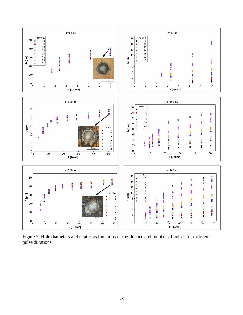
Figure 7 depicts the measured diameter and depth values of the drilled holes, as functions of the pulse
duration, fluence, and number of pulses. It can be observed that for pulse durations of 100 ns and 200 ns,
the number of pulses has little influence on the hole diameter but is highly effective towards increasing
the depth, which is a consequence of larger thermal penetration in the material. A decrease in the
measured diameters is visible for the two pulse durations with higher numbers of pulses (after the 10th

15
pulse for τ=100 ns, and the 7th pulse for τ=200 ns), as a consequence of the deposition of spattered
substrate material around the hole entrance. In both cases, this phenomenon is observed as a decrease in
the rate at which the drilling depth increases. In comparison to the TiN coating, the substrate material,
AISI M2 possesses a similar thermal penetration depth (α) but only half the reflectivity at the laser
wavelength (R) and half the melting temperature (Tm) (see Table I). The change in machining behaviour
from coating to substrate material serves as a critical point in multiple-pulse ablation. Although not
measured directly, a comparison of the physical properties shows that AISI M2 would reach melting and
boiling points easier with the applied laser energy. Accordingly, the substrate should possess an ablation
threshold that is significantly lower than that of the TiN coating. It should be considered that due to
differences in the physical properties of the coating and substrate, the material removal mechanism
changes between these layers. Furthermore, higher amounts of molten AISI M2 are expected, due to the
lower melting temperature and increased absorptivity of this material. At this point, material removal can
be achieved via either direct vaporisation, vaporisation from the molten phase or melt expulsion. The
way in which material is removed in the presence of high amounts of the molten phase is critical, because
this fact determines the machining quality. Melt ejection can occur due to the recoil pressure of the
vaporising material, causing the material to splash in the radial direction. With increasing fluence, the
molten material breaks into vapour and droplets as a result of explosive boiling [21]. The fraction of melt
generated depends on the pulse length and shape, as well as the fluence and number of pulses. As
previously mentioned, the heat penetration depth increases significantly as the pulse duration moves from
12 ns to 200 ns. In the case of 100 ns and 200 ns pulses, the mechanism of material removal from the
coating is observed to be direct vaporisation; in contrast, the mechanism for the AISI M2 substrate is
melt ejection, due to the recoil pressure of the vapour phase. The recast layer around the deep holes is
characterised by the deposition of large and intact substrate pieces on the coating, rather than the
micrometre- and submicrometre-sized droplets observed during explosive boiling (see insets of Figure
16
7). During melt ejection, some of the expelled material is re-deposited around the entrance and walls of
the hole, causing hole narrowing. Consequently, shadowing effects develop, reducing the amount of laser
energy that reaches the bottom of the drilled hole [22]. Moreover, as the hole depth increases, the ejection
of molten material becomes more difficult, leading to condensation inside the hole. The build-up of
material inside the hole and around its entrance causes a decrease in the ablation rate. With 100 ns and
200 ns pulses, the hole depth increases asymptotically for depths greater than 8 µm. In this size region,
the hole depth is significantly larger than the coating thickness, thus the reduction in ablation depth is
associated with the melt formation of the steel substrate and the resulting effects. In the case of the 12 ns
pulse duration, such a drop in the rate of increase of the diameter or depth of a hole is not visible with
increasing pulse number. The pulse duration is sufficiently short that it is able to prevent an excessive
quantity of the molten phase from developing on the substrate material. Even when the hole depth is
greater than the coating thickness, the ablation process is still dominated by vaporisation, and melt
ejection is avoided. This avoids hole narrowing and reduction in the material removal rate. Accordingly,
similar material removal rates exist for the substrate and coating materials for the pulse duration of 12
ns. As a result, no asymptotic behaviour is observed for the hole depth.
Another important phenomenon observed with the shorter 12 ns pulse duration is damage accumulation
phenomenon. The hole diameter visibly increases when the number of pulses is increased, suggesting the
presence of damage accumulation. The phenomenon was first reported by Jee et al. [23], followed by
extensive application to the ablation of various materials, including TiN [24-26], using ultrashort ps – fs
pulses. The incubation effect is expressed as a reduction in the threshold fluence as:
Fth(N)=Fth(1)NS-1 Eq. (13)
where Fth(N) and Fth(1) are the ablation threshold fluence of N pulses and a single-pulse, respectively,
and S is the incubation coefficient. Lower numbers of S correspond to higher degrees of damage

17
incubation, thus causing the ablation threshold to be lowered. To calculate the ablation thresholds for
different numbers of pulses at 12 ns of pulse duration, conditions between 3 and 36 pulses were extracted,
because these conditions do not correspond to holes deeper than the thickness of the coating material.
Figure 8 shows the calculated threshold fluences with the fitted model, as expressed in Eq. (13). The
experimentally observed decrease in the threshold occurs from Fth(1)=2.15 J/cm2 for a single-pulse to
Fth(36)=1.04 J/cm2 for 36 pulses. The calculated incubation coefficient was S=0.8 ± 0.02. In the literature,
the reported incubation coefficient of TiN is S=0.87 with a pulse duration of 130 fs at a pulse repetition
rate of 2 Hz and laser wavelength of 800 nm [24]. Compared to the literature, the coefficient calculated
in this study depicts higher damage incubation. This can be attributed to the longer pulse duration and
higher pulse repetition rate (20 kHz). On metals, the incubation effect has been attributed both to stress-
strain energy storage induced on the material during laser ablation and to changes in the surface
topography that lead to changes in the absorption characteristics, according to Jee et al. (τ=10 ns, λ=1064
nm PRR=10 Hz). The incubation observed on the processing of polymeric materials (PMMA) with UV
light was attributed to the photoinduced formation of defect centres, which enhanced the absorption of
UV light (τ=20 ns, λ=248 nm PRR=2 Hz) [25]. More recently, damage incubation during the laser
micromachining of ITO semiconductors was attributed to the accumulation of plastic deformation (τ=10
ps, λ=1064 nm PRR=200-1000 kHz) [26]. In this study, the incubation observed on TiN fits better with
the increase in absorption due to changes in surface topography, as can be observed from the SEM
images. Typically observed in fs and ps pulsed machining, the damage accumulation factor also indicates
that with 12 ns pulses, the thermal interaction of the beam on the material is limited. The short duration
of the pulse allows melt-free machining on the TiN coating, which yields an increase of the hole diameter
due to local changes in the optical properties rather than thermal propagation in the radial direction. The
incubation effect also has practical implications regarding the productivity of micromachining.
Essentially, low energy, short pulses can be used when machining materials with high ablation
18
thresholds. Under such conditions, it is not necessary to increase the pulse duration or energy, thereby
avoiding the degrading effects related to melt generation. Productivity can be compensated by increasing
the pulse repetition rate, that is, by applying smaller energy packages at higher frequency. However, the
limit to the highest applicable pulse repetition rate should also be investigated to avoid heat build-up in
the material or the generation of excessive amounts of plasma, which can attenuate the laser beam
intensity by scattering or absorption. The present study did not consider the effect of pulse repetition rate;
however, it is expected that the productivity of TiN microdrilling with a pulse duration of 12 ns can be
matched to that of 200 ns by increasing the pulse repetition rate to approximately 200 kHz. However, to
extrapolate the results to such a degree would require experimental verification, especially to investigate
the mentioned degrading effects.
4. Conclusions
Single- and multiple-pulse laser ablation of TiN coatings was studied using a MOPA fibre laser, with
programmable pulse shapes and durations between 12 ns - 200 ns. The laser pulses employed in this
study were characterised by fast ascending peaks and a decaying tail, which generated a non-symmetric
behaviour compared to Gaussian–like pulse shapes. It was experimentally observed that the pulse
duration changed the ablation threshold conditions. Shorter pulses required less energy but higher peak
power to initiate ablation. Because the pulse shape changed in a non-symmetric manner with the change
of pulse energy for a given pulse duration, the pulse shape was decomposed into its initial peak and
decaying tail. The decomposition was also expressed mathematically, and a regression model was fitted
to the extracted data. The model effectively demonstrated that the energy added in the tail in fixed peak
power conditions resulted in the saturation of the ablated region. Although this approach is based on
statistical methods, it satisfactorily quantifies the observed phenomenon and the effects of the pulse
components, representing a novel attempt to tackle this problem.

19
In the multiple-pulse study, the effect of pulse duration on hole depth evolution was further investigated.
Compared to the shortest pulse duration (12 ns), longer pulses (100 ns, 200 ns) were more efficient in
the removal of material from the TiN coating. In comparison, the shortest pulses required higher amounts
of total energy to drill the same amount of volume. This effect was attributed to the larger thermal
penetration obtained with longer pulses, which caused increased material removal. Drilling beyond the
coating thickness while using pulse durations of 100 and 200 ns decreased the hole quality by spattering
the substrate material. Due to the lower melting temperature and increased absorption of the laser
wavelength, a larger amount of molten layer was generated on the substrate. Thus, the substrate material
was ejected in melt form from the realised hole and then condensed around the hole entrance and walls.
Such conditions did not occur with 12 ns pulses, due to the small extent of confinement of the melt
fraction during the process. The number of pulses did not significantly influence the diameter when pulse
durations of 100 ns and 200 ns were employed. However, with 12 ns pulses, the number of pulses
noticeably influenced the hole diameter. This phenomenon was expressed by the effects of damage
incubation due to changes in material topography, causing higher absorption.
In terms of engineering applications, the results show that there is a larger margin of operation for the
micromachining of TiN coatings within the so-called short pulse regime of ns pulses. High-quality
machining was demonstrated to be possible, without compromising productivity. Moreover, the fibre
lasers presented advantages of robust architecture, simple operation, low capital and operation costs,
rendering the applicability of the micromachining of thin surface coatings industrially viable based on
this process. In the case of TiN, it was demonstrated that for percussion drilling operations, significant
control of hole diameter and depth was achievable. In particular, spatter-free machining conditions were
demonstrated, even when drilling beyond the coating into the substrate. For potential laser surface
texturing applications, such conditions could be a good solution for increasing the dimple depth without
damaging the TiN coating, when machining on substrate materials that are more fragile and strip of easily
20
during operation [27]. Moreover, the addition of pulse duration as a processing parameter extended the
operational space. It was possible to realise hole diameters smaller than the laser beam size, as small as
15 µm on one end and up to 50 µm on the other. The hole depth was effectively controlled within the
limited thickness of the coating (approximately 4 µm). Such flexibility in terms of hole geometry
manipulation should allow the design of patterns and shapes with better precision.

21
References
[1] H.E. Rebenne, D.G. Bhat, Review of CVD TiN coatings for wear-resistant applications: deposition processes,
properties and performance. Surface and Coatings Technology 63 (1994) 1-13
[2] S. Hogmark, S. Jacobson, M. Larsson, Design and evaluation of tribological coatings, Wear 246 (2000) 20–
33
[3] A. Shenhar, I. Gotman, S. Radin, P. Ducheyne, E.Y. Gutmanas, Titanium nitride coatings on surgical
titanium alloys produced by a powder immersion reaction assisted coating method: residual stresses and fretting
behaviour. Surface and Coatings Technology 126 (2000) 210-218
[4] H.C. Man, Q.Wang, X.Guo, Laser surface microdrilling of Ti and laser gas nitride Ti for enhancing fixation
of dental implants, Optics and Lasers in Engineering 48 (2010) 583–588
[5] A.J. Dowling, M.K. Ghantasala, J.P. Hayes, E.C. Harvey, E.D. Doyle, Excimer laser micromachining of TiN
films from chromium and copper sacrificial layers, Smart Mater. Struct. 11 (2002) 715–721
[6] L. Vandoni, A.G. Demir, B. Previtali, N. Lecis, D. Ugues, Wear Behavior of Fiber Laser Textured TiN
Coatings in a Heavy Loaded Sliding Regime, Materials 5, (2012) 2360-2382
[7] S. Marimuthu, A.M.Kamara, D.Whitehead, P.Mativenga, L.Li, Laser removal of TiN coatings from WC micro-
tools and in-process monitoring, Optics & Laser Technology 42, (2010) 1233–1239
[8] B.N. Chichkov, C. Momma, S. Nolte, F. von Alvensleben, A. Tunnerman, Femtosecond, picosecond and
nanosecond laser ablation of solids, Appl. Phys. A 63, (1996) 109-115
[9] B. Gakovic, M. Trtica, T.M. Nenadovic, B.J. Obradovic, TEA CO2 laser-induced damage of low-thickness
TiN coatings, Thin Solid Films 343-344 (1999) 269-272
[10] M.S. Trtica, B.M. Gakovic, L.T. Petkovska, V.F. Tarasenko, A.V. Fedenev, E.I. Lipatov, M.A. Shulepov,
Surface modifications of TiN coating by the pulsed TEA CO2 and KrCl laser, Applied Surface Science 225 (2004)
362–371
[11] M. S. Trtica, V.F. Tarasenko, B.M. Gakovic, A.V. Fedenev, L.T. Petkovska, B.B. Radak, E.I. Lipatov,
M.A. Shulepov, Surface modifications of TiN coating by pulsed TEA CO2 and XeCl lasers, Applied Surface
Science 252 (2005) 474–482
[12] T.V. Kononenko, S.V. Garnov, S.M. Pimenov, V.I. Konov, V. Romano, B. Borsos, H.P. Weber, Laser
ablation and micropatterning of thin TiN coatings, Appl. Phys. A 71 (2000) 627–631
[13] J. Bonse, M.Geuß, S. Baudach, H. Sturm, W.Kautek, The precision of the femtosecond-pulse laser ablation
of TiN films on silicon, Appl. Phys. A 69 [Suppl.] (1999) S399–S402
[14] W. O’Neill, K. Li, High-Quality Micromachining of Silicon at 1064 nm Using a High-Brightness MOPA-
Based 20-W Yb Fiber Laser, IEEE Journal of Selected Topics in Quantum Electronics, 15 (2) (2009) 462 – 470
[15] Fundamentals of Modeling for Metals Processing, in ASM Handbook, Vol 22A, 2009, pp. 599–601, Eds.
D.U. Furrer, S.L. Semiatin, Online Edition, American Society for Metals, Metals Park,
http://products.asminternational.org/hbk/index.jsp, last access: 19 February 2014
[16] W.M. Steen, Laser Material Processing, 3rd Ed., Springer-Verlag, London (2003) pp.79, 198
[17] H.O. Pierson, Handbook of Refractory Carbides and Nitrides, William Andrew, New Jersey (1996) pp. 181–
208

22
[18] A. Schlegel.,P. Wachter, J.J. Nickl., H. Lingg, Optical properties of TiN and ZrN, J. Phys. C: Solid State
Phys.10 (1977) 4889-4896
[19] A. Bendavid, P.J. Martin, R.P. Netterfield, T.J. Kinder, The properties of TiN films deposited by filtered arc
evaporation, Surface and Coatings Technology 70 (1994) 97—106
[20] J.M. Liu, Simple technique for measurements of pulsed Gaussian-beam spot sizes, Optics Letters 7 (5) (1982)
196-198
[21] N.M. Bulgakova, A.V. Bulgakov, Pulsed laser ablation of solids: transition from normal vaporization to phase
explosion. Appl. Phys. A 73, (2001) 199–208
[22] W. Schulz, U. Eppelt, R. Poprawe, Review on laser drilling I. Fundamentals, modeling, and simulation.
Journal of Laser Applications 25(1) (2013) 012006-1- 012006-17
[23] Y. Jee, M.F. Becker, R.M. Walser, Laser-induced damage on single-crystal metal surfaces. J. Opt. Soc. Am.
B/ 5(3) (1988) 648-659
[24] J. Bonse, P. Rudolph, J. Kruger, Baudach, W. Kautek, “Femtosecond pulse laser processing of TiN on
silicon”. Applied Surface Science 154–155 (2000) 659–663
[25] G.B. Blanchet, P. Cotts, C.R. Fincher Jr., Incubation: Subthreshold ablation of poly-(methyl methacrylate)
and the nature of the decomposition pathways. Journal of Applied Physics 88 (5) (2000) 2975-2978
[26] S. Xiao, E.L. Gurevich, A. Ostendorf, Incubation effect and its influence on laser patterning of ITO thin film.
Appl Phys A 107 (2012) 333–338
[27] A.G. Demir, N. Lecis, B. Previtali, D. Ugues, Scratch resistance of fiber laser surface textured TiN coatings,
Surface Engineering 29 (9) (2013) 654-659
23
List of tables
Tables
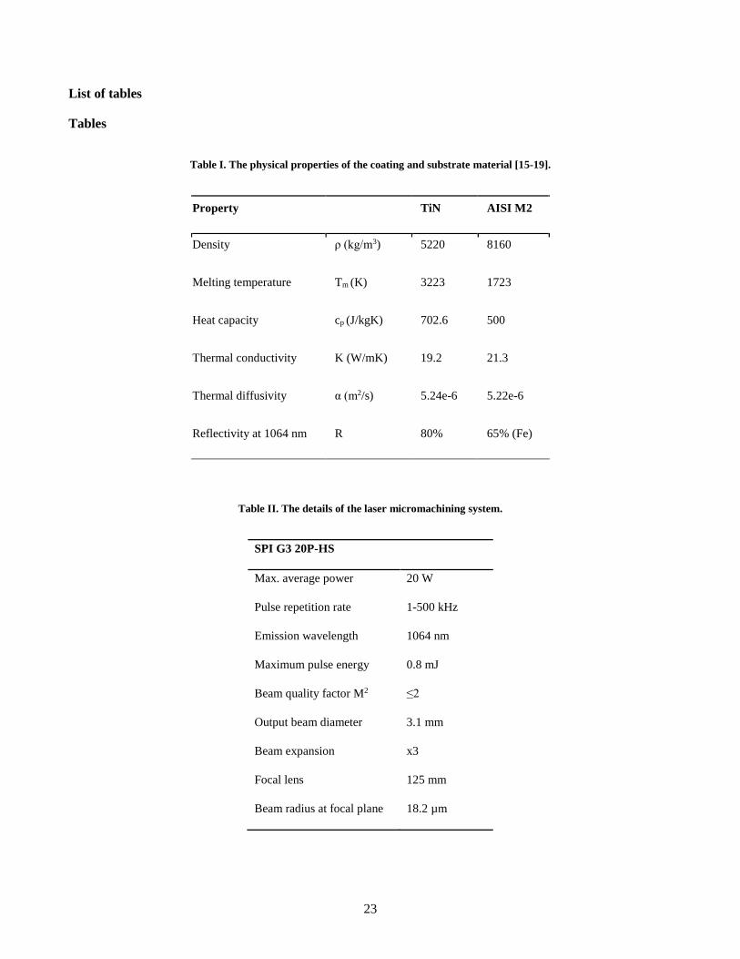
Table I. The physical properties of the coating and substrate material [15-19].
Property TiN AISI M2
Density ρ (kg/m3) 5220 8160
Melting temperature Tm (K) 3223 1723
Heat capacity cp (J/kgK) 702.6 500
Thermal conductivity K (W/mK) 19.2 21.3
Thermal diffusivity α (m2/s) 5.24e-6 5.22e-6
Reflectivity at 1064 nm R 80% 65% (Fe)
Table II. The details of the laser micromachining system.
SPI G3 20P-HS
Max. average power 20 W
Pulse repetition rate 1-500 kHz
Emission wavelength 1064 nm
Maximum pulse energy 0.8 mJ
Beam quality factor M2 ≤2
Output beam diameter 3.1 mm
Beam expansion x3
Focal lens 125 mm
Beam radius at focal plane 18.2 µm

24
Table III. The parameter sets of the single and multiple pulse studies.
Single pulse study
Pulse duration 12 ns 30 ns 65 ns 100 ns 150 ns 200 ns
Pulse energy 5-77 µJ 7-114 µJ 13-193 µJ 19-262 µJ 31-320 µJ 72-356 µJ
Focal position 0 mm
Multiple pulse study
Pulse duration 12 ns 100 ns 200 ns
Pulse energy 9-36 µJ 19-262 µJ 72-356 µJ
Number of pulses 9-81 3-14 3-9
Focal position 0 mm
Pulse repetition rate 20 kHz

25
List of Figures
Figure 1. The shape characteristics of the different pulse durations.
Figure 2. The evolution of ablated zones with similar energy (Ep) levels and different pulse durations.
The small circles in the ablated regions with pulse durations of 200 ns and 12 ns are reported in higher
magnification insets to show the crack dimensions. The diameter of the magnified region is 7.7 µm.

26
Figure 3. The evolution of ablated zones with similar peak power (Ppeak) levels and different pulse
durations. The small circles in the ablated regions with pulse durations of 200 ns and 12 ns are reported
in higher magnification insets to show the crack dimensions. The diameter of the magnified region is
7.7 µm.
Figure 4. The results of the single-pulse ablation study: changes in the fluence and irradiance thresholds
as functions of pulse duration; the theoretical value of the laser beam radius (w0); the estimated values
for the laser beam based on the non-linear regression method and values of threshold fluence (Fth) and
irradiance (Ith) for different pulse durations. The error bars represent the 95% confidence interval for
the mean.

27
Figure 5. The effect of the decomposed pulse components on the radius of the ablated area. The inset
reports the decomposition of the pulse components, depicting the peak, tail and added energy in the tail
(ΔE).
Figure 6. A comparison of holes with similar geometric properties obtained with different pulse
durations, energy levels and number of pulses.
28
Figure 7. Hole diameters and depths as functions of the fluence and number of pulses for different
pulse durations.

29
Figure 8. The fluence threshold as a function of the number of pulses for pulse duration of 12 ns. The
error bars represent the 95% confidence interval for the mean.