latency measurements of v2x communication by
TRANSCRIPT
Latency Measurements of V2X Communication
by
Uday Kumar Bejawada
A thesis submitted in partial fulfillment
of the requirements for the degree of
Master of Science in Engineering
(Automotive Systems Engineering)
in the University of Michigan-Dearborn
2017
Master’s Thesis Committee:
Professor Weidong Xiang, Chair
Associate Professor Jinhua Guo
Associate Professor Hafiz Malik

ii
Acknowledgements
I take immense pleasure to express my profound gratitude and deep regards to my academic
supervisor ‘Prof. Weidong Xiang’ for his exemplary guidance, monitoring and constant
encouragement throughout the course of this thesis. I would also like to thank him for offering me
thesis in my field of interest and equipping with all basic needs, which helped my work to be
interesting and productive.
I would also like to thank ‘Prof. Jiabo Zhang’ for giving me an opportunity to take his guidance. I
am obliged to colleagues of “laboratory” for their friendly sense of humour, creating energetic and
enthusiastic working environment.
Additional thanks to the “University of Michigan Dearborn” who have identified ways to help
students succeed.
I am grateful for the cooperation of ‘Dr. Pankaj Mallick’ and ‘Ms. Sherry Boyd’ for their
encouragement and in departmental aspects during the period of my thesis.
Finally, yet importantly, I would like to express my heartfelt thanks to my beloved parents and
brother for their blessings and support, my friends for their help and wishes for the successful
completion of this project.
iii
Table of Contents
Acknowledgements ......................................................................................................................... ii
List of Tables .................................................................................................................................. v
List of Figures ................................................................................................................................ vi
List of Abbreviations .................................................................................................................... vii
Abstract ........................................................................................................................................ viii
CHAPTER 1: INTRODUCTION .................................................................................................. 1
1.1 DESCRIPTION ................................................................................................................ 2
1.2 SECURITY AND SAFETY IN V2X COMMUNICATION ........................................... 2
1.3 MINIMUM REQUIREMENTS FOR V2X COMMUNICATION ................................. 3
1.3.1 CHANNEL REQUIREMENTS................................................................................ 3
1.3.2 Transmit Power Accuracy......................................................................................... 3
1.3.3 PATH HISTORY REFERENCE DESIGN .............................................................. 3
CHAPTER 2: DATA INTERPRETATION .................................................................................. 5
2.1 NMEA FROM GARMIN GLOBAL POSITIONING SYSTEM SENSOR .................... 5
2.2 DESIRED INFORMATION OF NMEA (National Marine Electronics Association) .... 6
2.3 ALGORITHM TO INTERPRET THE NMEA DATA ................................................... 8
2.3.1 SYNCHRONOUS INPUT/ OUTPUT ...................................................................... 8
2.3.2 ASYNCHRONOUS INPUT/ OUTPUT ................................................................... 8
2.4 VEHICLE CAN DATA VIA OBD DONGLE .............................................................. 14
2.5 ALGORITHM TO INTERPRET THE CAN PACKETS .............................................. 15
CHAPTER 3: NETWORK CONFIGURATION ........................................................................ 17
iv
3.1 LOCAL NETWORK...................................................................................................... 17
3.2 REMOTE NETWORK .................................................................................................. 19
3.3 ALGORITHM FOR NETWORK INTERFACE ........................................................... 20
CHAPTER 4: LATENCY MEASUREMENTS .......................................................................... 32
4.1 SCENARIOS IMPLEMENTED .................................................................................... 32
4.2 SCENARIOS OVERVIEW ........................................................................................... 32
4.3 Conclusion ...................................................................................................................... 33
REFERENCES ............................................................................................................................. 34
v
List of Tables
TABLE 1: GARMIN 10X TECHNICAL SPECIFICATIONS ............................................................ 5
TABLE 2: GGPGA DEFINED BY NMEA 0183 ...................................................................... 6
vi
List of Figures
FIGURE 1: RESEARCH WORK APPROACH ............................................................................... 1
FIGURE 2: WAAS SYSTEM [5] ............................................................................................. 6
FIGURE 3: NMEA SENTENCES ............................................................................................. 7
FIGURE 4: VEHICLE CAN BUS INFORMATION ..................................................................... 14
FIGURE 5: DESIRED INFORMATION WITH TIME STAMP ........................................................ 16
FIGURE 6: LOCAL NETWORK CONFIGURATION ................................................................... 17
FIGURE 7: ALGORITHM FLOWCHART ................................................................................. 18
FIGURE 8: REMOTE NETWORK CONFIGURATION ................................................................. 19
vii
List of Abbreviations
B
BSM (Basic Safety Message) ..................... 2
C
CAN (Controller Area Network) ............ 7, 1
D
D2D (Device to Device) ............................. 7
DSRC (Dedicated Short Range
Communications) .................................... 7
G
GNSS (Global Navigation Satellite System)
................................................................. 2
GPS (Global Positioning System) ............... 7
H
Host Vehicle (HV) ...................................... 3
L
Long Term Evolution) ............................ 7, 1
P
Path History (PH) ........................................ 3
Path Prediction (PP) .................................... 3
S
SA (selective availability) ........................... 5
SAE (Society of Automotive Engineers)
J2735 ....................................................... 2
T
TCP (Transmission Control Protocol) ........ 1
Time of Flight (TOF) .................................. 1
U
UDP (User Datagram Protocol) .................. 1
viii
Abstract
V2X communication plays one of the important roles for future autonomous vehicle. Current V2X
communication is more directed towards DSRC (Dedicated Short Range Communications). What if
the DSRC law is not enforced and some other technology such as D2D (Device to Device) based on
LTE (Long Term Evolution) will provide good results and become possible alternative.
The scope of this project is to have a sniffer that has the capability to process transmit and receive
the data and could able to interface all of the following devices DSRC, LTE and D2D (LTE based
communication without involvement of Base Station) and any other possible medium of
communication for V2X communication. And also, to have a database that has the capability to help
in the future of autonomous vehicles. This thesis explains the research study, done for one of the
performance evaluation of V2X communication. It can be further continued to develop a device and
a server with more functionalities for V2X communication.
In V2V communication network, performance evaluation is one of the key factors that need to be
considered. To address the evaluation criteria, I have analyzed the elapsed time in reading the GPS
(Global Positioning System) sensor and CAN (Controller Area Network) bus information from the
vehicle before transmitting the data to the Network (IEEE802.11p or LTE) and also after the
transmission. I have developed a c code, which can read the data from the GPS sensor and the CAN
bus, and add a time stamp to the real time data to analyze the elapsed time.
1
CHAPTER 1: INTRODUCTION
In V2X communication networks, the elapsed time in receiving the CAN bus information
from the CAN network of the vehicle should be taken into consideration, prior to the transmission of
data to the other vehicle. Once the data is transmitted either by IEEE802.11p or LTE, Time of Flight
(TOF) comes into picture. To estimate the overall performance of V2X communication network
these two time factors need to be considered. A mobile service can be used to provide the live
updates of the traffic situation on the road to the users 1. To get the live updates, the users need to
transmit and receive the data from the remote server when they are driving on the road. The
objective of this thesis is to determine the performance of IEEE802.11p and LTE as vehicular
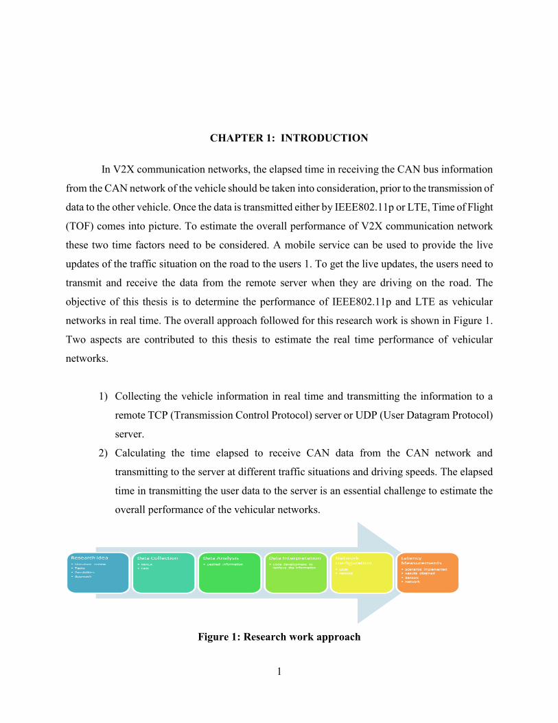
networks in real time. The overall approach followed for this research work is shown in Figure 1.
Two aspects are contributed to this thesis to estimate the real time performance of vehicular
networks.
1) Collecting the vehicle information in real time and transmitting the information to a
remote TCP (Transmission Control Protocol) server or UDP (User Datagram Protocol)
server.
2) Calculating the time elapsed to receive CAN data from the CAN network and
transmitting to the server at different traffic situations and driving speeds. The elapsed
time in transmitting the user data to the server is an essential challenge to estimate the
overall performance of the vehicular networks.
Figure 1: Research work approach
2
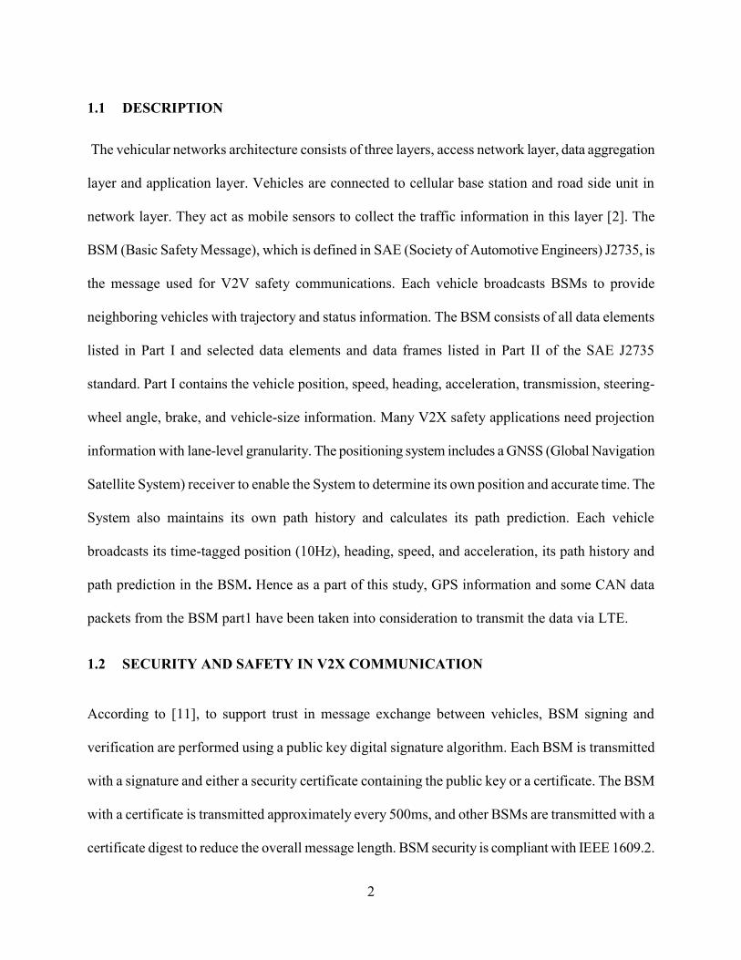
1.1 DESCRIPTION
The vehicular networks architecture consists of three layers, access network layer, data aggregation
layer and application layer. Vehicles are connected to cellular base station and road side unit in
network layer. They act as mobile sensors to collect the traffic information in this layer [2]. The
BSM (Basic Safety Message), which is defined in SAE (Society of Automotive Engineers) J2735, is
the message used for V2V safety communications. Each vehicle broadcasts BSMs to provide
neighboring vehicles with trajectory and status information. The BSM consists of all data elements
listed in Part I and selected data elements and data frames listed in Part II of the SAE J2735
standard. Part I contains the vehicle position, speed, heading, acceleration, transmission, steering-
wheel angle, brake, and vehicle-size information. Many V2X safety applications need projection
information with lane-level granularity. The positioning system includes a GNSS (Global Navigation
Satellite System) receiver to enable the System to determine its own position and accurate time. The
System also maintains its own path history and calculates its path prediction. Each vehicle
broadcasts its time-tagged position (10Hz), heading, speed, and acceleration, its path history and
path prediction in the BSM. Hence as a part of this study, GPS information and some CAN data
packets from the BSM part1 have been taken into consideration to transmit the data via LTE.
1.2 SECURITY AND SAFETY IN V2X COMMUNICATION
According to [11], to support trust in message exchange between vehicles, BSM signing and
verification are performed using a public key digital signature algorithm. Each BSM is transmitted
with a signature and either a security certificate containing the public key or a certificate. The BSM
with a certificate is transmitted approximately every 500ms, and other BSMs are transmitted with a
certificate digest to reduce the overall message length. BSM security is compliant with IEEE 1609.2.

3
LTE security is compliant with 3GPP [12]. However, this thesis work doesn’t discuss the security
and focuses only on latency.
1.3 MINIMUM REQUIREMENTS FOR V2X COMMUNICATION
V2X communication should meet the requirements mentioned in [11]. Some of the minimum
requirements that need to be met by the V2X communication system are outlined in this section.
1.3.1 CHANNEL REQUIREMENTS
The System shall transmit BSMs on channel with 10 MHz channel spacing.
The System shall transmit BSMs using an 802.11 data rate of 6 Mbps.
After the first BSM generated after System device startup, the System shall generate each
subsequent BSM within tolerance rate of (-10msec) to (+10msec) of its scheduled generation
time.
1.3.2 Transmit Power Accuracy
The DSRC Radio Subsystem shall meet the 802.11 transmitter requirements for 10 MHz channel
spacing with QPSK and ½ rate coding.
1.3.3 PATH HISTORY REFERENCE DESIGN
The Path History (PH) module for the V2V communications System uses a history of the past GNSS
locations traversed by the Host Vehicle (HV) and computes an adaptable, concise PH representation
of recent vehicle movement over a certain distance (200-300 meters). The PH communicated by a
vehicle provides other vehicles with information needed for predicting the roadway geometry.

4
PH plays an important role in target vehicle classification, relative to the HV, regarding the roadway.
There are different methods for design and implementation of the PH module. Three different design
methods are described here, each with a slightly different approach.
Path Prediction (PP) for the V2V safety communications System utilizes dynamics information
provided by the vehicle to estimate the driver’s intended future path. The estimate is provided
without dependence on future road geometry information obtained from outside sources (e.g., map
databases, vehicle probes). In order to determine if the LTE can meet the minimum V2X
communication requirement, the first step that has been considered to determine the latency is
outlined in this thesis work.
PP carries out the following basic operations:
Gathers vehicle dynamics information.
Computes path radius using dynamics information to represent the driver’s intended future
path:
Radius = 1/curvature (ρ).
Computes confidence of the predicted path based upon the ra``te of change of the vehicle
dynamics to infer transient conditions (i.e., non-steady-state conditions).
5
CHAPTER 2: DATA INTERPRETATION
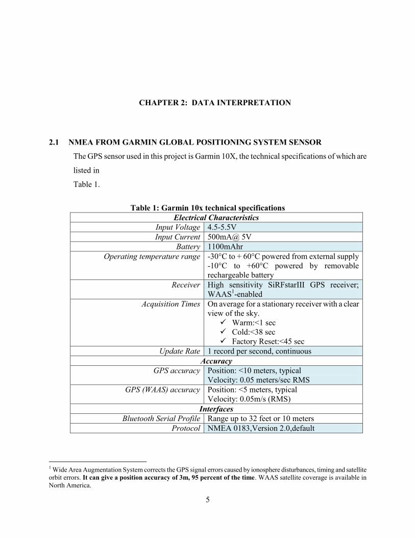
2.1 NMEA FROM GARMIN GLOBAL POSITIONING SYSTEM SENSOR
The GPS sensor used in this project is Garmin 10X, the technical specifications of which are
listed in
Table 1.
Table 1: Garmin 10x technical specifications
Electrical Characteristics
Input Voltage 4.5-5.5V
Input Current 500mA@ 5V
Battery 1100mAhr
Operating temperature range -30°C to + 60°C powered from external supply
-10°C to +60°C powered by removable
rechargeable battery
Receiver High sensitivity SiRFstarIII GPS receiver;
WAAS1-enabled
Acquisition Times On average for a stationary receiver with a clear
view of the sky.
Warm:<1 sec
Cold:<38 sec
Factory Reset:<45 sec
Update Rate 1 record per second, continuous
Accuracy
GPS accuracy Position: <10 meters, typical
Velocity: 0.05 meters/sec RMS
GPS (WAAS) accuracy Position: <5 meters, typical
Velocity: 0.05m/s (RMS)
Interfaces
Bluetooth Serial Profile Range up to 32 feet or 10 meters
Protocol NMEA 0183,Version 2.0,default
1 Wide Area Augmentation System corrects the GPS signal errors caused by ionosphere disturbances, timing and satellite
orbit errors. It can give a position accuracy of 3m, 95 percent of the time. WAAS satellite coverage is available in
North America.

6
As shown in Figure 2 the accuracy of GPS system subjects to degradation with SA (selective
availability) on and improves with SA off and WAAS.
15m: typical GPS position accuracy without SA.
3-5m: typical differential GPS (DGPS) position accuracy.
<3m: typical WAAS position accuracy.
Figure 2: WAAS system [5]
2.2 DESIRED INFORMATION OF NMEA (National Marine Electronics Association)
As shown in Figure 3, NMEA 0183 consists of various sentences. The GGPGA consists the global
positioning system fix data, which is described in Table 2.
Table 2: GGPGA Defined by NMEA 0183
Name Example
Data
Description
Sentence Identifier $GPGGA Global Positioning System Fix Data
Time 170834 17:08:34 Z
Latitude 4219.2152,
N
42d 19.2152' N or 42d 19' 12.912" N
Longitude 08314.0246,
W
83d 14.0246' W or 83d 14' 1.4760" W
Fix Quality:
0=Invalid
1=GPS fix
2=DGPS fix
1 Data is from a GPS fix
Number of Satellites 06 6 Satellites are in view
Horizontal Dilution of
Precision (HDOP)
1.5 Relative accuracy of horizontal
position
Altitude 249.7, M 280.2 meters above mean sea level
Height of geoid above WGS84
ellipsoid
-34.0, M -34.0 meters

7
Time since last DGPS update blank No last update
DGPS reference station id blank No station id
Checksum *69 Used by program to check for
transmission errors
Figure 3: NMEA sentences
A C program is developed to interpret the latitude and longitude data from GPGGA received. The
GPGGA has the following format.
$GPGGA,hhmmss.ss,llll.ll,a,yyyyy.yy,a,x,xx,x.x,x.x,M,x.x,M,x.x,xxxx*hh
The program is to,
1) Read the complete NMEA sentences sent from the GARMIN GPS 10X sensor via Bluetooth.
2) Capture GPGGA string and write to a data buffer.
3) Extract desired information including timestamp and latitude and longitude.
4) Loop for next data.
8
2.3 ALGORITHM TO INTERPRET THE NMEA DATA
For the serial communication between the GPS module and the windows PC, the Bluetooth interface
is established. In windows reading from and writing to communication ports is like the file input and
output. Functions for serial I/O uses the same functions as file I/O. Reading and writing to
communication ports in windows can be done either synchronously or asynchronously.
2.3.1 SYNCHRONOUS INPUT/ OUTPUT
In synchronous I/O, the calling thread is blocked when an operation is taking place. Once the
operation is complete, the function will return and the thread can continue with the next operation.
This is useful in multithreaded applications, because when one thread is blocked on an I/O operation,
other threads can still perform work. However, the application should serialize the ports correctly.
The drawback in this operation is that if one thread is blocked waiting for the I/O operation, all other
threads that call a communications API will be blocked until the original operation completes.
2.3.2 ASYNCHRONOUS INPUT/ OUTPUT
In Asynchronous I/O, a port open for overlapped operations allows multiple threads to perform the
I/O operations at the same time, thus allowing to do other work while the operations are incomplete.
The overlapped operations allow a single thread to issue multiple requests of different type and do
work in the background while the operations are incomplete, thus allowing more flexibility and
efficiency.
Asynchronous operation is not a good for portability in comparison with synchronous operation,
because it is not supported by most of the operating systems. Multithreading is supported by most of
the operating systems, therefore synchronous operation might be the best choice for portability.
Between issuing requests and processing the results, some synchronization must take place, in both
single-threaded and multithreaded applications. One thread should be blocked until the result of an
operation is available. Asynchronous I/O allows a thread to do some work between the time of the
request and its completion, thus providing the advantage for better responsiveness.
According to [13] for opening and closing a communications resource handle and for performing
read and write operations, “CreateFile, closehandle, readfile, and writefile” will provide the basic
interface. As the first step to open a handle to a communication resource the process uses the create

9
file function. For example, specifying COM1 opens a handle to a serial port. The handle returned by
’createfile’ to identify the resource in any of the functions that access the resource can be used by
any thread of the process. The following attributes need to be specified while calling a create file
function, type of read/ write access, whether the handle can be inherited by child process and
whether the handle can be used in asynchronous I/O operations. More information about ‘createfile’
function to open or create an I/O device can be found at [14].
The code developed for reading the GPS NMEA sentences works as follows:
Step1:
// Scans for an available COM port in a specified maximum and minimum range
// The maximum and minimum range must be defined by the user
for (n = scan_max ; n >= scan_min ; --n)
{
// Once the COM port is identified, the COM should be opened to read or write the data
hSerial = CreateFile(device_name, GENERIC_READ|GENERIC_WRITE, 0, 0,
OPEN_EXISTING, FILE_ATTRIBUTE_NORMAL, 0);
if (hSerial!=INVALID_HANDLE_VALUE)
{
// Assign the device number and stop scanning the ports
dev_number = n;
break; // stop scanning COM ports
}
// if it results in invalid handle value display the error code
}
Step2:
// Once the serial port is successfully opened, set the device parameters
// Baudrate (default 9600), 1 start bit, 1 stop bit, no parity
dcbSerialParams.DCBlength = sizeof(dcbSerialParams);
if (GetCommState(hSerial, &dcbSerialParams) == 0)
exit_message("Error getting device state", 1);
dcbSerialParams.BaudRate = baudrate;
10
dcbSerialParams.ByteSize = 8;
dcbSerialParams.StopBits = ONESTOPBIT;
dcbSerialParams.Parity = NOPARITY;
if(SetCommState(hSerial, &dcbSerialParams) == 0)
exit_message("Error setting device parameters", 1);
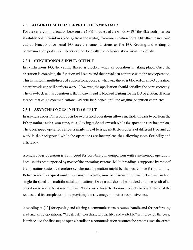
Step3:
Read the incoming data as characters, to avoid running into infinite loop when no data is received set
COM port timeout settings.
timeouts.ReadIntervalTimeout = 50;
timeouts.ReadTotalTimeoutConstant = 50;
timeouts.ReadTotalTimeoutMultiplier = 10;
timeouts.WriteTotalTimeoutConstant = 50;
timeouts.WriteTotalTimeoutMultiplier = 10;
if(SetCommTimeouts(hSerial, &timeouts) == 0)
exit_message("Error setting timeouts", 1);
Step4:
Read the data to a specified buffer of defined length
char message_buffer[MESSAGE_LENGTH];
DWORD bytes_read;
Step5:
Read the messages in the correct format, by identifying the delimiters that are used to separate the
NMEA sentences.
while(1)
{
// Read next character
ReadFile(hSerial, &c, 1, &bytes_read, NULL);
if (bytes_read != 1) continue;
if (state == 1)
{
// State 1: Waiting for '<' character to start message
n = 0;
11
strcpy(message_buffer, "");
if (c == '<') state = 2;
}
else if (state == 2)
{
// State 2: Reading id one digit at a time
if (c >= '0' && c <= '9') n = 10*n + (c-48);
else if (c == '@') state = 3;
else state = 1;
}
else if (state == 3)
{
// Got a '@' character, so now reading actual message
if (n != id) state = 1;
else if (c != '>') strncat(message_buffer, &c, 1);
else if (c == '>') state = 4;
if (strlen(message_buffer) >= MESSAGE_LENGTH-1) state = 4;
}
else if (state == 4)
{
// State 4: Display complete message
fprintf(stdout, "%s\n", message_buffer);
state = 1;
}
else state = 1;
}
}
return 0;
}
Step6:
12
Close the serial port in case of error or when the user presses a specific key defined in the code to
terminate program.
Step7:
To interpret a specific NMEA sentence out of the buffer data, a string comparison function is
required. For this a structure containing the GPS NMEA string info can be created.
struct {
int timeZone;
// flag to be used, when a valid sentence begins
bool flagRead;
// valid GPS fix and data available
bool flagDataReady;
// hold parsed words for one given NMEA sentence
char words[20][15];
// hold the received checksum for one given NMEA sentence
char szChecksum[15];
// will be set to true for characters between $ and * only
bool flagComputedCks;
// used to compute checksum and indicate valid checksum interval (between $ and * in a given
sentence)
// compute numeric checksum for a given sentence
int checksum;
// after getting * start cuttings the received checksum
bool flagReceivedCks;
// Parse the received checksum
int index_received_checksum;
// Indexing the word
int wordIdx;
int prevIdx;
int nowIdx ;
// globals to store parser results
bool positionFixIndicator; //GPGGA
13
bool dataValid; //GPRMC
float longitude; // GPRMC and GPGGA
float latitude; // GPRMC and GPGGA
unsigned char UTCHour, UTCMin, UTCSec, // GPRMC and GPGGA
UTCDay, UTCMonth, UTCYear; // GPRMC
int satellitesUsed;// GPGGA
float speed; // GPRMC
}gps;
Step8:
Comparing the string in the buffer to read the data as words in the GPGGA sentence by parsing the
delimiters.
if (strcmp(gps.words[0], "$GPGGA") == 0) {
/*
// Check GPS Fix: 0=no fix, 1=GPS fix, 2=Dif. GPS fix
if (gps.words[6][0] == '0') {
gps.positionFixIndicator = false;
// clear data
// gps.res_fLatitude = 0;
// gps.res_fLongitude = 0;
gps.flagDataReady = false;
Reading the time information from the GPS
gps.UTCHour = charToInt(gps.words[1][0]) * 10 + charToInt(gps.words[1][1]);
gps.UTCHour = gps.UTCHour-4; // Michigan time zone
gps.UTCMin = charToInt(gps.words[1][2]) * 10 + charToInt(gps.words[1][3]);
gps.UTCSec = charToInt(gps.words[1][4]) * 10 + charToInt(gps.words[1][5]);
Reading the latitude and longitude information
gps.latitude = strtof(gps.words[2], NULL);
gps.longitude = strtof(gps.words[4], NULL);
Reading the number of satellites
14
gps.satellitesUsed = (int)strtof(gps.words[7], NULL);
Step9:
Create a data file and write the data to the file. Continue the loop till the user terminates the program
or if an error is encountered, and close the file.
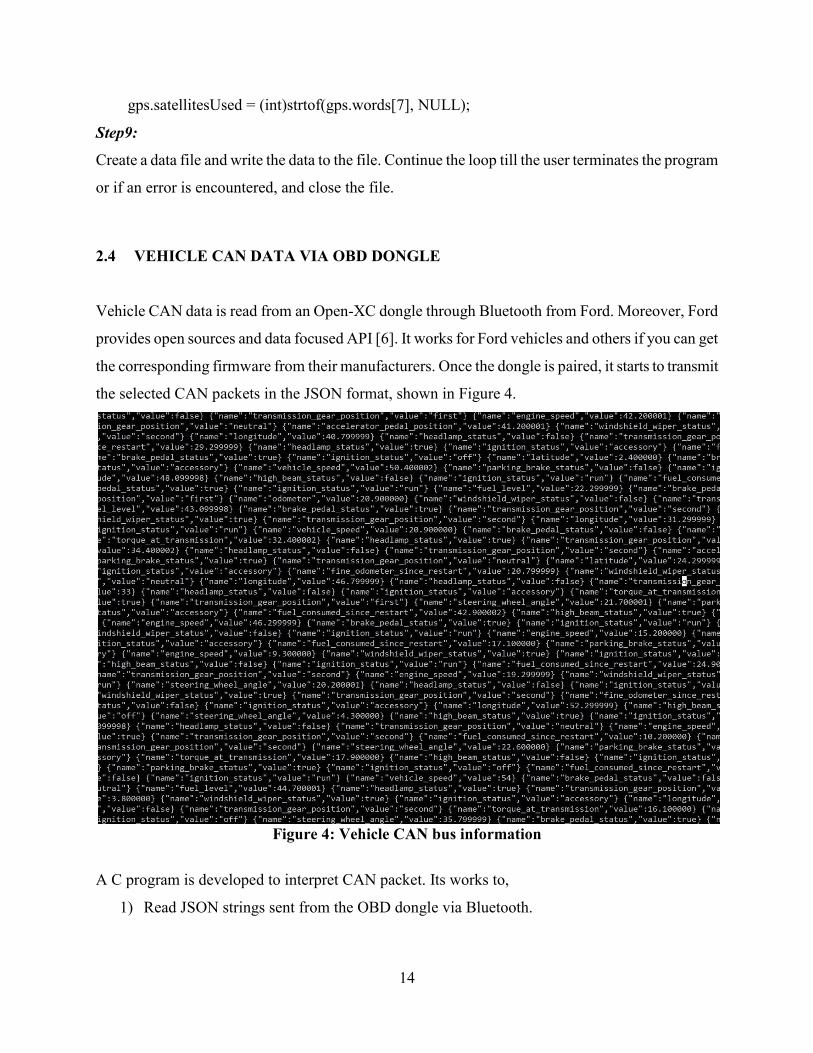
2.4 VEHICLE CAN DATA VIA OBD DONGLE
Vehicle CAN data is read from an Open-XC dongle through Bluetooth from Ford. Moreover, Ford
provides open sources and data focused API [6]. It works for Ford vehicles and others if you can get
the corresponding firmware from their manufacturers. Once the dongle is paired, it starts to transmit
the selected CAN packets in the JSON format, shown in Figure 4.
Figure 4: Vehicle CAN bus information
A C program is developed to interpret CAN packet. Its works to,
1) Read JSON strings sent from the OBD dongle via Bluetooth.
15
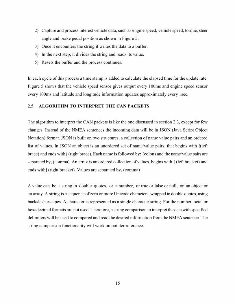
2) Capture and process interest vehicle data, such as engine speed, vehicle speed, torque, steer
angle and brake pedal position as shown in Figure 5.
3) Once it encounters the string it writes the data to a buffer.
4) In the next step, it divides the string and reads its value.
5) Resets the buffer and the process continues.
In each cycle of this process a time stamp is added to calculate the elapsed time for the update rate.
Figure 5 shows that the vehicle speed sensor gives output every 100ms and engine speed sensor
every 100ms and latitude and longitude information updates approximately every 1sec.
2.5 ALGORITHM TO INTERPRET THE CAN PACKETS
The algorithm to interpret the CAN packets is like the one discussed in section 2.3, except for few
changes. Instead of the NMEA sentences the incoming data will be in JSON (Java Script Object
Notation) format. JSON is built on two structures, a collection of name value pairs and an ordered
list of values. In JSON an object is an unordered set of name/value pairs, that begins with {(left
brace) and ends with} (right brace). Each name is followed by: (colon) and the name/value pairs are
separated by, (comma). An array is an ordered collection of values, begins with [ (left bracket) and
ends with] (right bracket). Values are separated by, (comma)
.
A value can be a string in double quotes, or a number, or true or false or null, or an object or
an array. A string is a sequence of zero or more Unicode characters, wrapped in double quotes, using
backslash escapes. A character is represented as a single character string. For the number, octal or
hexadecimal formats are not used. Therefore, a string comparison to interpret the data with specified
delimiters will be used to compared and read the desired information from the NMEA sentence. The
string comparison functionality will work on pointer reference.
16
Figure 5: Desired information with time stamp
17
CHAPTER 3: NETWORK CONFIGURATION
In order investigate the latency for the LTE, I have categorized the network configuration into two
types, local and the remote network. I have done the socket programming to create server and client
configuration for both TCP (Transmission Control Protocol) and UDP (User Datagram Protocol).
3.1 LOCAL NETWORK
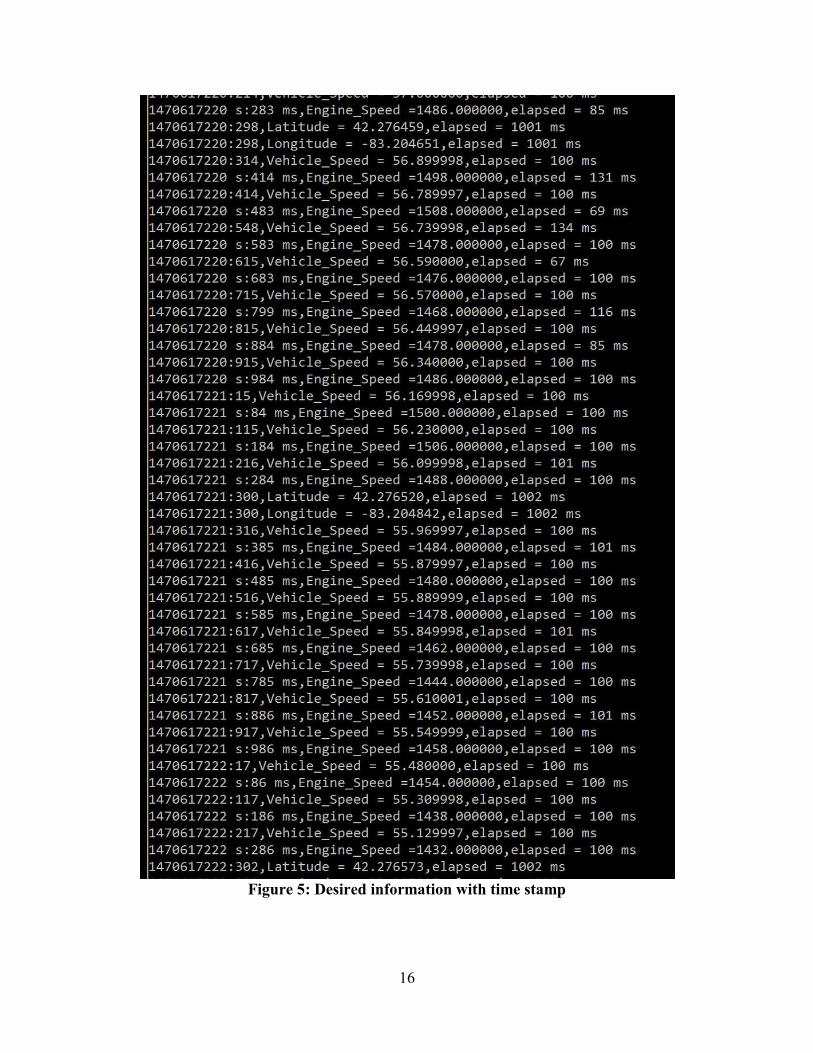
The local network configuration is as shown in Figure 6. The client is considered to be a car
transmitting the CAN packets and GPS information to the server. Once the server receives the
information, it will store the data. The client and the server are connected to the local network of
University of Michigan Dearborn.
Figure 6: Local network configuration
18
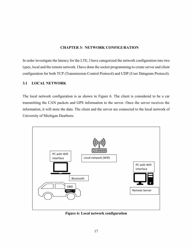
A code has been developed for the local network configuration as shown in Figure 7. The code
functionality and the evaluation is as follows:
Step 1:
The server is configured with a standard receiving buffer size and IP network listening to a
port.
The client is configured to transmit the data to the server IP address on to the specific port
that the server is configured to listen.
Dummy packets are transmitted to test the established communication between the server
and the client.
Step 2:
Client is now connected to the OBD dongle to interface the CAN network.
Once the client establishes the connection with the server it will start receiving the CAN
packets from the OBD dongle.
The received packets will be transmitted to the server and the client will not wait for the
acknowledgement from the server.
The server stores the data sent from the client. It listens to the client until the client closes the
connection.
Figure 7: Algorithm Flowchart
19
The above two steps are tested by connecting the client and server to the local network (Same Wi-Fi
network). No data has been lost when the network interface is local. The TCP network connection is
like the UDP with one difference that the client transmits the information to the server after
receiving the acknowledgement from the server. The TCP network is tested in both local network
and through internet.
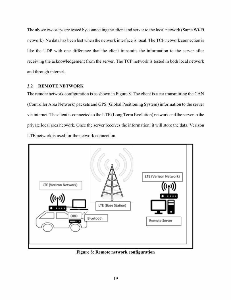
3.2 REMOTE NETWORK
The remote network configuration is as shown in Figure 8. The client is a car transmitting the CAN
(Controller Area Network) packets and GPS (Global Positioning System) information to the server
via internet. The client is connected to the LTE (Long Term Evolution) network and the server to the
private local area network. Once the server receives the information, it will store the data. Verizon
LTE network is used for the network connection.
Figure 8: Remote network configuration
20
For local and the remote network configurations a time stamp is added on the server side and also on
the client side to determine the latency. Latency observed for the local network is within the range of
0 to 16ms. Latency measured at different scenarios for the remote network configuration are
discussed in chapter 4.
3.3 ALGORITHM FOR NETWORK INTERFACE
Network specific software that communicates with the network specific device driver and the IP
layer to provide the IP layer with consistent interface can be considered as the network interface.
Each network interface has a network address. Based on the destination address of the packet to be
transmitted the IP layer selects the appropriate network interface. A socket will be an endpoint in a
two-way communication link between two programs running on the network. It is bounded to a port
number so that the TCP layer can identify the application to where data need to be sent. A TCP
connection can be uniquely identified by its endpoints. Each endpoint is a combination of an IP
address and the port number. Thus, providing the access of having multiple connections between
clients and server.
The basic TCP client server connection involves three steps, the client sends a synchronous
message, the server sends an acknowledge with the clients synchronous message and contains the
servers synchronous message, then the client sends an acknowledge for the servers synchronous
message. Synchronous message indicates that the segment is being used to initialize a connection.,
and acknowledge indicates that the device sending the segment is conveying the acknowledgement
for a message it has received. The algorithm works as follows:
Step1:
21
The server opens a passive connection, creating a transmission control block for the connection and
prepares for the recipient connection from (Synchronous message) from the client. The client cannot
connect to server until the server opens a passive connection.
Step2:
The client creates a transmission control block for the connection and sends a synchronous message
to the server. The server listens to the client.
Step3:
The server receives the synchronous message from the client. It sends a synchronous message and
acknowledgement message back to the client that contains an acknowledgment form clients and
server synchronization. The client waits to receive an acknowledgement to the synchronous message
it has sent, and also for the server synchronous message.
Step4:
The client receives the synchronous and acknowledge message from the server and sends an
acknowledgement for the server synchronization. The client ready to establish connection. Server
waits for the acknowledgement from the client for the synchronous message it has send previously.
Step5:
The clients will wait for the server to establish connection. The server receives the acknowledgement
to its synchronization and establishes the connection.
Step6:
The client and server will be ready for the data transfer.
The client code below will explain the functions performed by the client.
// Attributes to initialize the socket
WSADATA wsaData;
SOCKET ConnectSocket = INVALID_SOCKET;
struct addrinfo *result = NULL,
*ptr = NULL,
hints;
char *sendbuf = "this is a test";
char recvbuf[DEFAULT_BUFLEN];
int iResult;
22
int recvbuflen = DEFAULT_BUFLEN;
// Validate the parameters
if (argc != 2) {
printf("usage: %s server-name\n", argv[0]);
return 1;
}
// Initialize Winsock
iResult = WSAStartup(MAKEWORD(2,2), &wsaData);
if (iResult != 0) {
printf("WSAStartup failed with error: %d\n", iResult);
return 1;
}
ZeroMemory( &hints, sizeof(hints) );
hints.ai_family = AF_UNSPEC;
hints.ai_socktype = SOCK_STREAM;
hints.ai_protocol = IPPROTO_TCP;
// Resolve the server address and port
iResult = getaddrinfo(argv[1], DEFAULT_PORT, &hints, &result);
if ( iResult != 0 ) {
printf("getaddrinfo failed with error: %d\n", iResult);
WSACleanup();
return 1;
}
// Attempt to connect to an address until one succeeds
for(ptr=result; ptr != NULL ;ptr=ptr->ai_next) {
// Create a SOCKET for connecting to server
ConnectSocket = socket(ptr->ai_family, ptr->ai_socktype,
ptr->ai_protocol);
if (ConnectSocket == INVALID_SOCKET) {
printf("socket failed with error: %d\n", WSAGetLastError());

23
WSACleanup();
return 1;
}
// Connect to server.
iResult = connect( ConnectSocket, ptr->ai_addr, (int)ptr->ai_addrlen);
if (iResult == SOCKET_ERROR) {
closesocket(ConnectSocket);
ConnectSocket = INVALID_SOCKET;
continue;
}
break;
}
freeaddrinfo(result);
if (ConnectSocket == INVALID_SOCKET) {
printf("Unable to connect to server!\n");
WSACleanup();
return 1;
}
// Send an initial buffer
iResult = send( ConnectSocket, sendbuf, (int)strlen(sendbuf), 0 );
if (iResult == SOCKET_ERROR) {
printf("send failed with error: %d\n", WSAGetLastError());
closesocket(ConnectSocket);
WSACleanup();
return 1;
}
// shutdown the connection since no more data will be sent
iResult = shutdown(ConnectSocket, SD_SEND);
if (iResult == SOCKET_ERROR) {
printf("shutdown failed with error: %d\n", WSAGetLastError());
closesocket(ConnectSocket);
24
WSACleanup();
return 1;
}
// Receive until the peer closes the connection
do {
iResult = recv(ConnectSocket, recvbuf, recvbuflen, 0);
if ( iResult > 0 )
printf("Bytes received: %d\n", iResult);
else if ( iResult == 0 )
printf("Connection closed\n");
else
printf("recv failed with error: %d\n", WSAGetLastError());
} while( iResult > 0 );
// cleanup
closesocket(ConnectSocket);
WSACleanup();
The server code below explains the basic functions implemented
WSADATA wsaData;
int iResult;
SOCKET ListenSocket = INVALID_SOCKET;
SOCKET ClientSocket = INVALID_SOCKET;
struct addrinfo *result = NULL;
struct addrinfo hints;
int iSendResult;
char recvbuf[DEFAULT_BUFLEN];
int recvbuflen = DEFAULT_BUFLEN;
// Initialize Winsock
iResult = WSAStartup(MAKEWORD(2,2), &wsaData);
25
if (iResult != 0) {
printf("WSAStartup failed with error: %d\n", iResult);
return 1;
}
ZeroMemory(&hints, sizeof(hints));
hints.ai_family = AF_INET;
hints.ai_socktype = SOCK_STREAM;
hints.ai_protocol = IPPROTO_TCP;
hints.ai_flags = AI_PASSIVE;
// Resolve the server address and port
iResult = getaddrinfo(NULL, DEFAULT_PORT, &hints, &result);
if ( iResult != 0 ) {
printf("getaddrinfo failed with error: %d\n", iResult);
WSACleanup();
return 1;
}
// Create a SOCKET for connecting to server
ListenSocket = socket(result->ai_family, result->ai_socktype, result->ai_protocol);
if (ListenSocket == INVALID_SOCKET) {
printf("socket failed with error: %ld\n", WSAGetLastError());
freeaddrinfo(result);
WSACleanup();
return 1;
}
// Setup the TCP listening socket
iResult = bind( ListenSocket, result->ai_addr, (int)result->ai_addrlen);
if (iResult == SOCKET_ERROR) {
printf("bind failed with error: %d\n", WSAGetLastError());
freeaddrinfo(result);
26
closesocket(ListenSocket);
WSACleanup();
return 1;
}
freeaddrinfo(result);
iResult = listen(ListenSocket, SOMAXCONN);
if (iResult == SOCKET_ERROR) {
printf("listen failed with error: %d\n", WSAGetLastError());
closesocket(ListenSocket);
WSACleanup();
return 1;
}
// Accept a client socket
ClientSocket = accept(ListenSocket, NULL, NULL);
if (ClientSocket == INVALID_SOCKET) {
printf("accept failed with error: %d\n", WSAGetLastError());
closesocket(ListenSocket);
WSACleanup();
return 1;
}
// No longer need server socket
closesocket(ListenSocket);
// Receive until the peer shuts down the connection
do {
iResult = recv(ClientSocket, recvbuf, recvbuflen, 0);
if (iResult > 0) {
27
printf("Bytes received: %d\n", iResult);
// Echo the buffer back to the sender
iSendResult = send( ClientSocket, recvbuf, iResult, 0 );
if (iSendResult == SOCKET_ERROR) {
printf("send failed with error: %d\n", WSAGetLastError());
closesocket(ClientSocket);
WSACleanup();
return 1;
}
printf("Bytes sent: %d\n", iSendResult);
}
else if (iResult == 0)
printf("Connection closing...\n");
else {
printf("recv failed with error: %d\n", WSAGetLastError());
closesocket(ClientSocket);
WSACleanup();
return 1;
}
} while (iResult > 0);
// shutdown the connection since we're done
iResult = shutdown(ClientSocket, SD_SEND);
if (iResult == SOCKET_ERROR) {
printf("shutdown failed with error: %d\n", WSAGetLastError());
closesocket(ClientSocket);
WSACleanup();
return 1;
}
28
// cleanup
closesocket(ClientSocket);
WSACleanup();
Now the message buffer filled with either vehicle data or GPS data or both can be transferred to
server from the car (Client). However, the above code is the basic functionality that works for only
one server and client configuration. To accept multiple clients few more functionalities are
developed to establish asynchronous communication (refer to section 2.3). For the local network, the
performance is similar to the single server client configuration. However, the performance
evaluation is still need to be tested on remote network configuration.
The code works as follows:
// Waits for the incoming connections
// Reads the set of socket descriptors
//clear the socket fd set
FD_ZERO(&readfds);
//add master socket to fd set
FD_SET(master, &readfds);
//add child sockets to fd set
for ( i = 0 ; i < max_clients ; i++)
{
s = client_socket[i];
if(s > 0)
{
FD_SET( s , &readfds);
}
}
//wait for an activity on any of the sockets, timeout is NULL , so wait indefinitely
activity = select( 0 , &readfds , NULL , NULL , NULL);
if ( activity == SOCKET_ERROR )
{
29
printf("select call failed with error code : %d" , WSAGetLastError());
exit(EXIT_FAILURE);
}
//If something happened on the master socket , then its an incoming connection
if (FD_ISSET(master , &readfds))
{
if ((new_socket = accept(master , (struct sockaddr *)&address, (int *)&addrlen))<0)
{
perror("accept");
exit(EXIT_FAILURE); }
//add new socket to array of sockets
for (i = 0; i < max_clients; i++)
{
if (client_socket[i] == 0)
{
client_socket[i] = new_socket;
printf("Adding to list of client sockets at index %d \n" , i);
break;
}
}
s = client_socket[i];
//if client present in read sockets
if (FD_ISSET( s , &readfds))
{
//get details of the client
getpeername(s , (struct sockaddr*)&address , (int*)&addrlen);
//Check if it was for closing , and also read the incoming message
valread = recv( s , buffer, recv_buflen, 0);
if( valread == SOCKET_ERROR)
{
int error_code = WSAGetLastError();
30
if(error_code == WSAECONNRESET)
{
//Somebody disconnected , get his details and close the connection
//Close the socket and mark as 0 in list for reuse
closesocket( s );
client_socket[i] = 0;
}
else
{
printf("recv failed with error code : %d" , error_code);
}
}
if ( valread == 0)
{
//Somebody disconnected, get his details and close
//Close the socket and mark as 0 in list for reuse
closesocket( s );
client_socket[i] = 0;
}
//Echo back the message that came in
else
{
//add null character, if you want to use with printf/puts or other string handling functions
buffer[valread] = '\0';
printf("%s:%d - %s \n" , inet_ntoa(address.sin_addr) , ntohs(address.sin_port), buffer);
send( s , buffer , valread , 0 );
}
}
}
closesocket(s);
WSACleanup();

31
The server code developed is a standalone application, waiting for incoming connections, if the user
terminates it. Each car connecting as a client will be assigned a unit port address within the
application. Whenever the client closes the connection, the port address within the application
assigned for that car will be deleted in the array, and will be assigned to new car that connects to the
server. Thus, establishing multiple stable connections.

32
CHAPTER 4: LATENCY MEASUREMENTS
4.1 SCENARIOS IMPLEMENTED
The scenarios that are considered for the simulation are as follows:
1) Scenario 1: Vehicle speed data received from the CAN bus is every 100 to 140ms. Projection
information received from the GPS sensor is every 1sec. TOF calculated when the car is located in
the parking slot within a range of 10miles radius from the server is 0 to 30ms.
2) Scenario 2: Vehicle speed data received from the CAN bus is every 100 to 140ms. Projection
information received from the GPS sensor is every 1sec. TOF calculated when the car is driving at
70mph around 450miles radius from the server in the dense forest area of Pennsylvania with average
signal connectivity is 300 to 400ms.
3) Scenario 3: Vehicle speed data received from the CAN bus is every 100 to 140ms. Projection
information received from the GPS sensor is every 1sec. TOF calculated when the car is driving at
40mph around 650miles radius from the server in the heavy traffic of New York city is 150 to
250ms.
4.2 SCENARIOS OVERVIEW
If we consider a worst case scenario that the traffic is moving at 70mph, then for each millisecond
each vehicle covers a distance of 0.032 meters or 0.105 foot. If we assume a time latency of 100ms
for the traffic update. Then each vehicle could able to transmit or receive a traffic update for every
3.2 meters or 10.5 foot approximately. If we assume that the vehicle speed sensor of vehicle
transmits information every 100ms. It adds up to the to a time latency of 100ms resulting to a time
lapse of 200ms. Therefore, it takes around 6.4meters or 21foot approximate distance to transmit the
information to the server
33
Similarly, if a GPS sensor could able to update every 100ms and if we assume a time latency of
100ms to transmit to the server. Every 3.2meters or 10.5foot the server gets the projection
information of vehicle and it adds to a time latency of network of 100ms in addition to reach the data
to the server resulting in 200ms time lapse. Therefore, reduction in the time latency and time lapse
plays an essential role in vehicular networks, in receiving the accurate and the reliable information of
the traffic update.
4.3 Conclusion
Many possible scenarios such as using IEEE802.11p and cellular networks at different ranges from
the server, and the speeds of multiple vehicles connected to the server can still be considered to
evaluate the time latency in the vehicular networks. However, the simulations that are outlined in
this paper with one vehicle connected to the server at different ranges and speeds, shows how
essential it is to determine the time latency to evaluate the overall performance of the vehicular
networks.
The simulations have shown that the traffic updates that can be sent to the server or received from
the server by the vehicles are affected by factors such as vehicle speed, range of server from the
vehicle and the signal connectivity of the network used.
34
REFERENCES
1. Ahmed S. Kaseb, Youngsol Koh, Everett Berry, Kyle McNulty, Yung-Hsiang Lu and Edward J.
Delp, "Multimedia content creation using global network cameras: The making of CAM2",
Signal and Information Processing (GlobalSIP) 2015 IEEE Global Conference on, pp. 15-18,
2015.
2. Yunshu Liu, Xuanyu Chen, Cailian Chen, and Xingping Guan,” Traffic Big Data Analysis
Supporting Vehicular Network Access Recommendation” Communications (ICC), 2016 IEEE
International Conference on,pp. 14 July 2016.
3. IEEE Trial-Use Standard for Wireless Access in Vehicular environments (WAVE) Resource
manager
4. Dedicated short range communications (DSRC) message set dictionary SAE J2735_201603
5. http://www8.garmin.com/aboutGPS/waas.html.
6. http://openxcplatform.com/
7. http://www.nmea.org/content/nmea_standards/nmea_0183_v_410.asp.
8. https://www.garmin.com/support/pdf/NMEA_0183.pdf
9. http://www.plaisance-pratique.com/IMG/pdf/NMEA0183-2.pdf
10. https://en.wikipedia.org/wiki/World_Geodetic_System
11. http://standards.sae.org/wip/j2945/
12. http://www.3gpp.org/DynaReport/33-series.htm
13. https://msdn.microsoft.com/en-us/library
14. https://msdn.microsoft.com/en-us/library/windows/desktop/aa363858(v=vs.85).aspx