lateral collapse of short-length sandwich tubes compressed...
TRANSCRIPT

Lateral collapse of short-length sandwich tubes compressed by
different indenters and exposed to external constraints
Ahmad Baroutaji a,*, Abdul-Alghani Olabi
b
(a) School of Mechanical and Manufacturing Engineering, Dublin City University, Glasnevin, Dublin 9, Ireland.
(b) University of the West of Scotland, School of Engineering, High Street, Paisley, PA1 2BE, UK.
Abstract:
In this paper, sandwich tube components which consist of thin-walled circular tubes
with aluminium foam core are proposed as energy absorption systems. The sandwich
tubes were laterally crushed under quasi-static loading conditions. The sandwich
tubes were crushed under two types of indenters and exposed to three different types
of external constraints. The collapsing behaviour and the energy absorption
responses of these systems were investigated by nonlinear finite element analysis
through ANSYS-LS-DYNA. Various indicators which describe the effectiveness of
energy absorbing systems were used as a marker to compare the various systems. It
was found that the sandwich tube systems compressed by cylindrical indenters
particularly the unconstrained system (STCIU) and the system with inclined
constraints (STCIIC) offered a very desirable force-deflection in which the force is
almost constant in the post collapse stage. The employing of external constraints was
noticed as a feasible method of increasing the SEA particularly when cylindrical
indenter is used.
Keywords: Sandwich tube, Energy absorbing systems, Lateral collapse, ANSYS-
LSDYNA, Aluminium foam.

Nomenclature
Symbol Definition Units
SEA Specific Energy Absorbed
Capacity J/kg
Weff Weight Effectiveness J/kg
eg Crush Efficiency -
eE Energy Efficiency -
Abbreviations
Acronym Definition
STFIU Sandwich tube flat plate indenter
unconstrained
STFIIC Sandwich tube flat plate indenter
inclined constraints
STFISC Sandwich tube flat plate indenter side
wall constraints
STFICC Sandwich tube flat plate indenter
combined constraints
STCIU Sandwich tube cylindrical indenter
unconstrained
STCIIC Sandwich tube cylindrical indenter
inclined constraints
STCISC Sandwich tube cylindrical indenter side
constraints
STCICC Sandwich tube cylindrical indenter
combined constraints

1 Introduction:
Of interest for thin-walled components used in crashworthiness application is to
enhance their energy absorption performance by using filler materials. Light material
such as honeycomb, cork, wood, foam and rubber are proposed to use as a filler
material in thin-walled components. Using of filler material along with thin-walled
component has enhanced the energy absorption of the whole structure. Structural and
weight efficiencies of these structures made these types of structures practical for
engineering applications. Using of foams as filler material in thin-walled tubes
provide several potential benefits for energy absorption. Numerous of researches
have been performed to investigate crush and energy absorption response of foam-
filled thin-walled tubes under axial loading. Examples include foam-filled circular
tubes (Borvik et al. [1]; Kavi et al. [2]; Toksoy and Guden [3]; Yan et al. [4]), foam-
filled square tubes (Hanssen et al. [5]; Santosa et al. [6]; Seitzberger et al. [7]; Zarei
and Kroger [8]), foam-filled conical tubes (Gupta and Velmurugan [9], Ahmad [10]),
foam-filled tapered rectangular tubes (Mirfendereski et al. [13]; Reid et al. [14]), and
foam-filled hat sections (Chen [15]; Song et al. [16]).
Overall, studies on the collapse behaviour and energy absorption response of foam-
filled tubes (either rectangular or circular cross-section) under lateral loading have
been less reported in the literature. Considering the importance of such structures, a
few numbers of studies have been performed to investigate the collapse behaviour
and energy absorption response of foam-filled tubes under lateral loading.
Fan et al. [17] have carried out a set of experiments to investigate the lateral
collapsing behavior of sandwich tubes. Variation of sandwich tubes with different
diameter to thickness ratios were employed in this study. Two types of bonding have
been used to assemble the foam core with solid tubes. In addition to experimental

work, numerical investigations through ABAQUS/Explicit have been performed to
validate the experimental results. It was found that three types of collapse patterns
are observed in lateral collapse of sandwich tubes termed as simultaneous collapse
pattern, simultaneous collapse pattern with facture of the foam core and sequential
collapse pattern. The experimental and numerical results showed that using of
sandwich tubes as energy absorber enhance the crush strength and energy absorption.
In a companion paper, Fan et al. [18] have experimentally and numerically examined
the dynamic response of sandwich tubes under lateral loading. It was reported that
the same collapse patterns in the quasi-static tests have also been observed in the
dynamic crushing experiments on the sandwich tubes. Non-symmetric deformation
pattern about the horizontal plane has been observed in the case of high impact
velocity. This behaviour is due to fact that plastic deformation starts at the section
near the impact region. In addition, critical velocity has been identified for mode
change and was related to t/D by means of dimensional analysis.
Increasing the energy absorption capacity of the tubular system by means of external
constraints was applied by many researchers such as Reddy and Reid [20], Reid [21]
and Morris et al. [22]. In general, it was reported that an externally constrained
system is a viable method to increase its energy absorbing capacity.
In the present paper, numerical investigations into the quasi-static lateral collapse of
sandwich tube systems have been performed. The FE model has been developed and
validated against existing experimental results in the literature. The sandwich tubes
have been compressed under flat and cylindrical indenters. Due to the strain
localization around the plastic hinges, external constraints have been employed to
increase the number of plastic hinges and then increase the volume of material

reaching plasticity. The aim of this work is to study the energy absorption
characteristics of sandwich tube systems.
2 Numerical Simulations
2.1 Material Properties:
As reported by Fan et al.[17], the sandwich tubes are prepared by cutting the outer,
inner and foam core separately and then assemble these three components together.
The material of outer and inner layers is the aluminium alloy AA6060T5. The foam
core was prepared by using ALPORAS®
aluminium foam. In order to obtain the
mechanical properties of the foam core, uniaxial compression tests of cylindrical
foam specimen were performed by Fan et al. [17] as shown in Fig. 1. The mechanical
properties of both AA6060T5 and ALPORAS® are the same as reported by Shen et
al.[19]. The three components of sandwich tubes were adhered together by using
thixotropic epoxy liquid glue (FORTIS AD825).
Table 1. Component material properties of the sandwich tubes [19].
Density (kg/m3)
Young’s
modulus (GPa)
Poisson’s ratio
Yield strength
Rp0.2 (MPa)
Hardening
modulus
AA6060T5 2760 69 0.3 150 345
ALPORAS® 230 ± 20 1.1 ± 0.1 0.33 1.5 ± 0.1 --

Fig. 1. Material properties of ALPORAS® foam [17].
2.2 Finite Element Model
The commercial explicit FE code ANSYS-LSDYNA was used for all finite element
modelling of sandwich tubes. Fig. 2 shows the FE model of a sandwich tube. A 3D-
structural solid element (solid 164) which has eight nodes with large strain, large
deflection and plasticity capabilities was used to model the foam core. Crushable
foam model was used to define the material of the ALPORAS® aluminium foam.
The Flat and cylindrical indenter were modelled as rigid body and constrained to
move vertically along the vertical y-axis. The base and external constraints were also
modelled as a rigid entity with all rotations and translations being fixed. Outer and
inner aluminium tubes were modelled by using shell element (SHELL163) with
Belytschko-Tsay element formulation. A bilinear kinematic hardening material
model was employed to define the material behaviour of the outer and inner
aluminium tubes. The mechanical properties of foam and aluminium tubes are as

listed in Table 1. Automatic ‘Surface to surface’ contact type was used to define the
contact between the outer tube and all rigid bodies. The perfect bonding between the
three components of the sandwich system was modelled by using Tied ‘node to
surface’ contact type between the foam core and both of the outer and inner tubes.
All models were subjected to symmetry boundary conditions in order to reduce the
simulation solve times. In general, explicit codes are mostly used to simulate the
impact events with high velocities. The quasi-static problems can also be simulated
by explicit codes with reasonable computing time and accuracy as addressed by [10].
Fig. 2. FE model of sandwich tube compressed by flat plate indenter.
The quasi-static loading was simulated by defining the motion of the moving rigid
body through applying a prescribed velocity on it. The velocity was increased within
ramping time tR=12.5 (ms) (this value provide an acceptable results) and then
followed by a constant velocity of 2 m/sec throughout the total time of loading tT as
shown in Fig. 3.
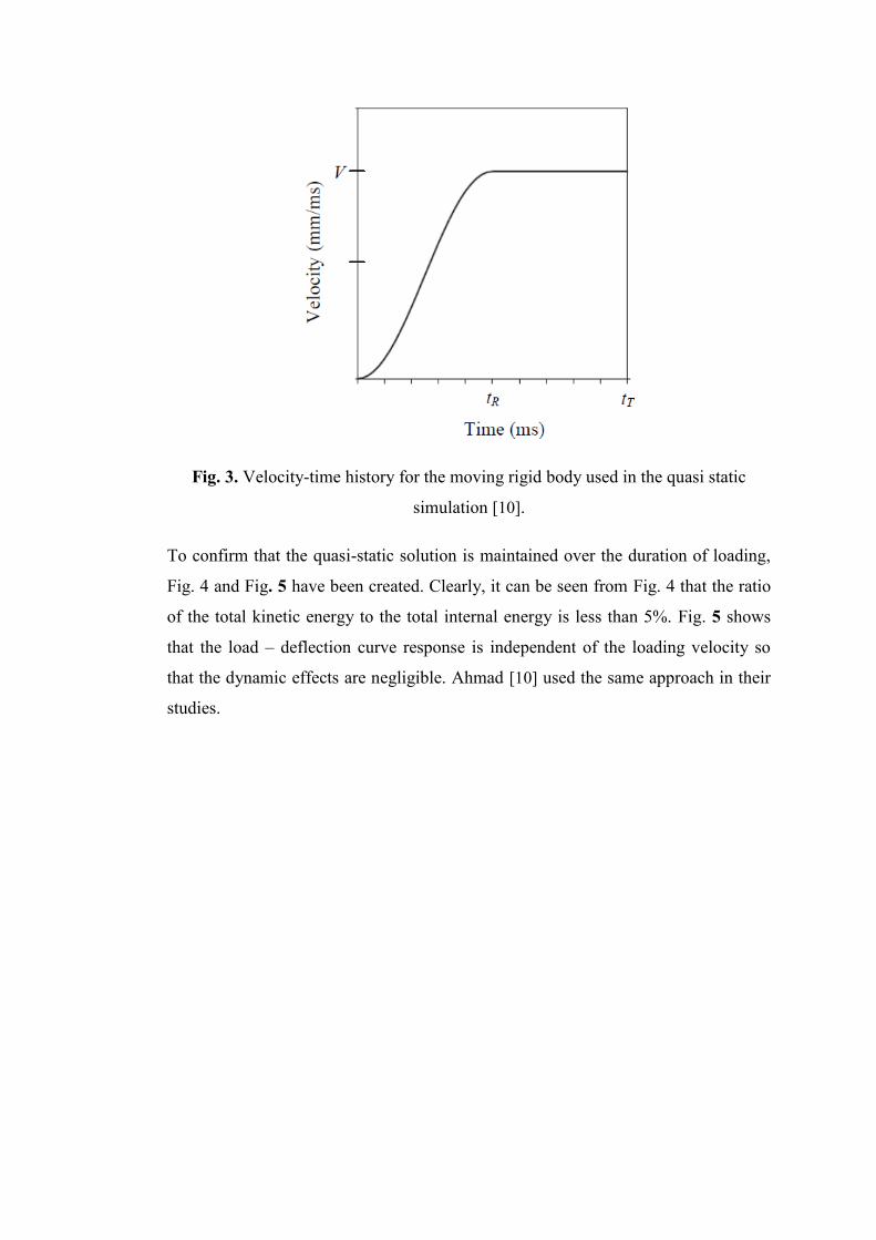
Fig. 3. Velocity-time history for the moving rigid body used in the quasi static
simulation [10].
To confirm that the quasi-static solution is maintained over the duration of loading,
Fig. 4 and Fig. 5 have been created. Clearly, it can be seen from Fig. 4 that the ratio
of the total kinetic energy to the total internal energy is less than 5%. Fig. 5 shows
that the load – deflection curve response is independent of the loading velocity so
that the dynamic effects are negligible. Ahmad [10] used the same approach in their
studies.

Fig. 4. Comparison of kinetic and internal energy for the FE model of sandwich
tube.
Fig. 5. Load –deflection response at three different velocities.
2.3 Validation of the Finite Element Model
To validate the FE model of sandwich tubes, the numerical results were compared
against existing experimental results presented by Fan et al. [17]. The experimental
data were obtained from analysis carried out by Fan et al. [17] on a sandwich tube
0
50
100
150
200
250
300
0 20 40 60 80 100
En
erg
y (J
)
Displacement (mm)
Internal Energy
Kinetic Enegy
0
1
2
3
4
5
0 20 40 60 80 100
Fo
rce
(kN
)
Displacement (mm)
v=2 m/sec v= 1 m/sec v=0.5 m/sec

with a geometry shape and dimension as displayed in Table 2. Fig. 6 shows the
quasi-static load-deflection curves for a sandwich tube compressed with flat plate
indenter. The results show a reasonable agreement between the existing experimental
results and present FE predictions. A slight under-prediction was offered by the FE
results in the post collapse stages. This under-estimation is due to tangential slippage
existed in the lower region of the sandwich tube which increases the contact area of
the outer tube during the experiment [17].
Table 2. Geometry and dimensions of the sandwich tube used for validation of the
present FE model.
Geometry Dimension
D1=150.2 [mm]-t1=3.28 [mm]
D2=127.1 [mm]-t2=2.69 [mm]
W=50 [mm]
Fig. 6. Comparison of FE and experimental results for the sandwich tube system
under quasi-static loading.

The collapse stages of the sandwich tube under lateral loading are presented in Fig.
7. It can be seen that the outer layer, inner layer and foam core were deformed
simultaneously. The same phenomena were also reported by Fan et al. [17].
Overall, the FE results showed an excellent agreement with experimental results for
lateral collapsing of sandwich tubes under quasi-static loading conditions.
Fig. 7. Collapse stages of sandwich tube as predicted by FE simulation.
3 Results and Discussion
3.1 Analysis of STFIU System
Fig. 8 shows the force-deflection response of the STFIU system. The STFIU has
been compressed up to 87 mm in order to avoid overloading and self-inner layer
contact. It can be seen that at the early stages of deformation the crush force is
increased linearly with the displacement. This stage is called as an elastic phase.
After the elastic phase the force starts to increase gradually as displacement
increases. This behavior is due to strain hardening characteristic of the aluminium
tubes, geometric change of the system and the hardening or densification of the foam
core during crushing. Fig. 9 plots the energy absorbed by each component of the
STFIU system. It can be seen that the greater contribution in energy dissipated by the
system were introduced by the foam core. The foam has dissipated around 44% of

whole energy at a displacement of 87 mm. The ratios of dissipated energy by outer
and inner tubes were respectively 31.7% and 24.4%. Fig. 10 shows the deformation
history of the STFIU system, it can be seen how the three components deform
simultaneously. The foam core did not deform severely with no tangential slippage
noticed at any stage. A symmetric collapse mode about both vertical and horizontal
planes was reported.
Fig. 8. Force and energy responses of the STFIU system.
Fig. 9. Energy absorbed by each component of the STFIU.

Fig. 10. Collapse sequence of the STFIU under quasi-static loading.
3.2 Analysis of STFIIC
External inclined constraints of angle 15 degree have been used to create STFIIC as
shown in Fig. 13. The force and energy responses of the STFIIC system are
presented in Fig. 11. It can be seen that similar responses to the unconstrained
system were obtained but with an increase in the resulting force being observed in
the post collapse stages. This increase is due to the presence of the constraints which
subject more volume of material to deformation as reported by Reid [21]. A
significant increase in the load value has been observed at a displacement of 70 mm.
This behaviour is due to the fact that outer tube starts to conform the shape of the
inclined constraints as shown in Fig. 12.
The contribution of each component in the energy dissipation is demonstrated in Fig.
12. An increase in dissipated energy by outer layer could be noticed in this system

due to use the inclined constraints. A ratio of 34% of the energy is recorded as a
contribution of outer layer in the STFIIC system.
The collapse modes at different stages of the STFIIC are plotted in Fig. 13. Using of
inclined constraints converts the collapse mode from being symmetric around two
axes into symmetric around the y-axis only. At displacement of 45mm the foam
experiences a significant plastic deformation at the lower region without any
tangential slippage.
Fig. 11. Force and energy responses of the STFIIC system.
Fig. 12. Energy absorbed by each component of the STFIIC.

Fig. 13. Collapse sequence of the STFIIC under quasi-static loading.
3.3 Analysis of STFISC
Fig. 14 shows the force-deflection response of the STFISC system. Presence of the
side constraints would prevent the horizontal diameter of the sandwich specimen
from moving laterally and thus exposing more material to plastic deformation. A
rapid increase in the force response can be noticed at almost 36 mm of deflection.
This behaviour is due to stiffening of the outer tube due to conforming to the shape
of side constraints. No more displacement is possible after the outer layer conforms
to the shape of side constraints as any further displacement might cause a structural
collapse to the outer layer. The outer tube has the larger contribution in the energy
absorbed by this system as shown in Fig. 12. At a displacement of 57 mm the outer
tube dissipated around 54% of energy while both of inner tube and foam core
dissipated an equal value of 23%. The stages of collapse modes of the STFISC are
presented in Fig. 16. It is clear that collapsing of this system is involved in the 6

hinges mechanism. Fig. 16 shows a non-symmetric collapse mode about the
horizontal axis at the early stages of the deformation ( . This is due to
presence of side constraints which create two additional plastic hinges in the halfway
between the side constraint and the moving rigid body. It can be seen that at
the plastic deformation took place at the upper part of the sandwich
tube while the bottom part hast not affected too much. As the deflection proceeds,
the additional plastic hinges move and merge with the basic plastic hinges so the
symmetric collapse mode can be noticed again at the late stages of the deformation
as shown in Fig. 16. It can be seen that the foam core undergoes a significant plastic
deformation particularly at the corner created between the sandwich tube and both of
indenter and side wall constraints.
Fig. 14. Force and energy responses of the STFISC system.

Fig. 15. Energy absorbed by each component of the STFISC.
Fig. 16. Collapse sequence of the STFISC under quasi-static loading.

3.4 Analysis of STFICC
The responses of the sandwich tube subjected to both combined constraints and
compressed by a flat indenter (STFICC) is presented in Fig. 17. Similarly to the
STFISC response, an increase in the force was observed near to 25 mm of the
displacement due to presence of external constraints. The outer tube has absorbed
more than the inner tube and foam core as shown in Fig. 18. This is because the
outer tube experiences a significant plastic deformation due to additional plastic
hinges created. The foam core also in this system has deformed extensively at the
final stages of the collapse and starts to slip out causing a reduction in the thickness
of the foam particularly at the corner of the specimen. Non-symmetric collapse mode
was noticed at all stages of the deformation, see Fig. 19. A value of 44 mm was
selected as a maximum displacement stroke for this system as any further
displacement might cause an overloading of the system and structural failure may
also take place.
Fig. 17. Force and energy responses of the STFICC system.

Fig. 18. Energy absorbed by each component of the STFICC.
Fig. 19. Collapse sequence of the STFICC under quasi-static loading.

3.5 Analysis of STCIU
The load-deflection response of the STCIU is displayed in Fig. 20. It can be seen that
at approximately 20 mm of the deflection, the system continues deforming with a
constant crush force. This type of response is termed as perfectly plastic response as
there is neither strain hardening nor strain softening. This perfectly plastic response
might be because of the opposed effect of the geometrical strain softening caused by
the cylindrical indenter and material strain hardening of both aluminium tube and
foam core. The foam core has dissipated more than the outer and inner tube as shown
in Fig. 21. The collapse mode was symmetric about both of x- and y-axis at the early
stages of deformation but then it was converted into non-symmetric mode about x-
axis as shown in Fig. 22. This unsymmetrical mode noticed at the late stages of
deformation is due to slight warping of the outer tube around the cylindrical indenter
to conform the shape of this indenter. The foam core has deformed more at the top
part of the system due to concentration of load caused by the cylindrical shape of the
indenter. A tangential slippage of the foam core might occur at this location.
Fig. 20. Force and energy responses of the STCIU system.

Fig. 21. Energy absorbed by each component of the STCIU.
Fig. 22. Collapse sequence of the STCIU under quasi-static loading.

3.6 Analysis of STCIIC
Fig. 23 shows the force-deflection response of the STCIIC. A slight increase in the
resulting force has been reported in the post collapse stages due to the presence of
inclined constraints. Similarly to the STCIU, an almost constant crushing force is
achievable in the STCIIC system which is a desirable feature in energy absorbing
systems. Both of outer tube and foam core have dissipated almost the same amount
of energy as shown in Fig. 24. The increase noticed in the energy absorbed by the
outer tube is due to presence of inclined constraints which make the plastic
deformation of the outer tube greater. Non-symmetric collapse mode about x-axis
can be noticed at all stages of the deformation (Fig. 25). A large plastic deformation
has been occurred to the foam core at the top and bottom region.
Fig. 23. Force and energy responses of the STCIIC system.

Fig. 24. Energy absorbed by each component of the STCIIC.
Fig. 25. Collapse sequence of the STCIIC under quasi-static loading.

3.7 Analysis of STCISC
Fig. 26 shows the force-deflection response of the STCISC. An increase in the
collapse load can be noticed in this system due to the introduction of side constraints.
At approximately 43 mm of the deflection, the reactive force increases gradually.
This behaviour is due to the fact that the upper part of the outer tube warps around
the cylindrical indenter in order to conform to its profile and at the same time the
side regions of the specimen partially conform to the shape of side constraints. The
outer tube of the system has dissipated more energy than both of inner and foam core
as shown in Fig. 27. This is due to the introduction of sidewalls which prevent the
horizontal diameter of the outer tube from displacing outward and expose more
volume of the outer tube material to plastic deformation. The stages of deformation
are shown in Fig. 28. It can be seen that the severe deformation of tubes was
localized at the upper portion of the structure while a slight deformation was noticed
at the lower portion of sandwich. As noticed in the previous systems (STCIU-
STCIIC), the foam core also in this system (STCISC) has experienced a significant
deformation at the top part of the specimen.

Fig. 26. Force and energy responses of the STCISC system.
Fig. 27. Energy absorbed by each component of the STCISC.

Fig. 28. Collapse sequence of the STCISC under quasi-static loading.
3.8 Analysis of STCICC
Fig. 29 depicts the numerical force-displacement response of a STCICC system. At
approximately the same deflection of 43mm as in the STCISC, the system began to
strain-harden. The energy responses and the collapse modes of the STCICC are
presented in Fig. 30 and Fig. 31, respectively. It can be seen that the responses and
collapse mode of the STCICC are very similar to the STCISC with no effect to
inclined constraints introduced in the STCICC system.

Fig. 29. Force and energy responses of the STCICC system.
Fig. 30. Energy absorbed by each component of the STCICC.
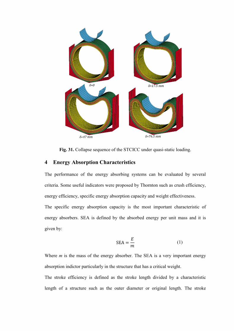
Fig. 31. Collapse sequence of the STCICC under quasi-static loading.
4 Energy Absorption Characteristics
The performance of the energy absorbing systems can be evaluated by several
criteria. Some useful indicators were proposed by Thornton such as crush efficiency,
energy efficiency, specific energy absorption capacity and weight effectiveness.
The specific energy absorption capacity is the most important characteristic of
energy absorbers. SEA is defined by the absorbed energy per unit mass and it is
given by:
(1)
Where m is the mass of the energy absorber. The SEA is a very important energy
absorption indictor particularly in the structure that has a critical weight.
The stroke efficiency is defined as the stroke length divided by a characteristic
length of a structure such as the outer diameter or original length. The stroke

efficiency for the lateral collapse of a circular tube can be defined by the following
equation
(2)
Where D is the outer diameter of the tube eg is considered as a good indicator for
describing the amount of material that can be used during collapse. This indictor is
very useful in the applications which have restrictions on the energy absorber space.
The energy efficiency indictor is given by
(3)
Where Fmax is the maximum load observed in the force-displacement response, Lo is
the original length of the absorber. It is recommended to maximize the energy
efficiency of the energy absorber. Ideally, to achieve the maximum value of eE, the
force-displacement response of the energy absorber should be a rectangle response.
The work effectiveness is a combination of the specific energy absorption capacity
with the crush efficiency indictor and it is defined as follows
(4)
This indictor is very useful for a structure which has restrictions on both weight and
space.
Fig. 32 presents the various energy absorbing indicators for various sandwich tube
systems analysed in this chapter. It can be seen that the systems compressed by
cylindrical indenter offer higher energy efficiencies particularly the STCIU-STCIIC
systems. This is due to their load-displacement responses which exhibit rectangular
or constant crushing force throughout their loading phase. The crush efficiency of
most systems is around 60%. Increasing of this value is possible particularly in the
systems compressed by a cylindrical indenter but this might cause an overloading for

the whole system and structural failure might take place particularly in the outer
component of the sandwich tube. In addition to structural failure, increasing of crush
efficiency might also cause a significant tangential slippage of the foam core
particularly at locations where the foam experience larger plastic deformation
(corners of STFISC and upper region of systems compressed by cylindrical
indenters). This might reduce the thickness of the foam core at these locations and
the contact of two layers might take place leading to absorbing energy in ineffective
manner. The STCISC and STCICC systems offer the higher work effectiveness
magnitude due to combination of great plastic deformation occurred in these systems
and maximum crush efficiency obtained.
Fig. 32. Comparison of effectiveness indicators for all systems analysed.

5 Conclusion
Based on existing experimental study, a finite element model has been developed to
investigate the energy absorption through sandwich circular tubes. Two types of
indenters have been used to compress the models. Concept of external constraints
has been used to increase the specific energy absorbed by the samples.
The main points concluded from this study are summarized below:
The sandwich circular tube presents an almost ideal response when a
cylindrical indenter is used particularly as shown in systems STCIU and
STCIIC.
Exposing the sandwich tube to external constraints allowed more volume of
the specimen to be deformed and increased the specific energy absorbed by
the tube. However, the presence of external constraints creates a limitation in
terms of increasing the crush efficiency as in systems (STFISC, STFICC).
The undesirable behavior of tangential slippage or failure of the foam core
can be avoided by decreasing the stroke length. This can be considered as a
disadvantage of the sandwich tube system as the crush efficiency offered by
them is lower than the empty circular tube.
According to energy absorption characteristics, the highest energy efficiency
is offered by (STCIU, STCIIC) systems and the highest magnitude of weight
effectiveness is introduced by (STCISC, STCICC) systems. It is
recommended to use a cylindrical indenter as alternative to flat plate indenter
in the sandwich tube systems.

6 References
[1] T. Børvik,O. Hopperstad,A. Reyes,M. Langseth,G. Solomos,T. Dyngeland
,International journal of crashworthiness .2003,8, 481.
[2] H. Kavi,A. K. Toksoy,M. Guden ,Mater Des .2006,27, 263.
[3] A. Toksoy,M. Güden ,Thin-walled structures .2005,43, 333.
[4] W. Yan,E. Durif,Y. Yamada,C. Wen ,Materials transactions .2007,48, 1901.
[5] A. G. Hanssen,M. Langseth,O. S. Hopperstad ,Int. J. Impact Eng. .2000,24, 347.
[6] S. P. Santosa,T. Wierzbicki,A. G. Hanssen,M. Langseth ,Int. J. Impact Eng.
.2000,24, 509.
[7] M. Seitzberger,F. G. Rammerstorfer,R. Gradinger,H. Degischer,M. Blaimschein,C.
Walch ,Int. J. Solids Structures .2000,37, 4125.
[8] H. Zarei,M. Kröger ,Thin-Walled Structures .2008,46, 214.
[9] N. Gupta,R. Velmurugan ,J. Composite Mater. .1999,33, 567.
[10] Z. Ahmad,D. Thambiratnam , Mater Des .2009,30, 2393.
[11] Z. Ahmad,D. P. Thambiratnam ,Comput. Struct. .2009,87, 186.
[12] Z. Ahmad,D. Thambiratnam,A. Tan ,Int. J. Impact Eng. .2010,37, 475.
[13] L. Mirfendereski,M. Salimi,S. Ziaei-Rad ,Int. J. Mech. Sci. .2008,50, 1042.
[14] S. Reid,T. Reddy ,Int. J. Mech. Sci. .1986,28, 623.
[15] W. Chen ,Int. J. Solids Structures .2001,38, 7919.
[16] H. Song,Z. Fan,G. Yu,Q. Wang,A. Tobota ,Int. J. Solids Structures .2005,42, 2575.
[17] Z. Fan,J. Shen,G. Lu ,Procedia Engineering .2011,14, 442.
[18] Z. Fan,J. Shen,G. Lu,D. Ruan ,Int. J. Impact Eng. .2012.
[19] J. Shen,G. Lu,L. Zhao,Q. Zhang ,Eng. Struct. .2012.
[20] T. Yella Reddy,S. Reid ,Int. J. Mech. Sci. .1979,21, 187.
[21] S. Reid ,Structural crashworthiness .1983,3.
[22] E. Morris,A. Olabi,M. Hashmi ,Thin-Walled Structures .2006,44, 872