lateral support - saice - geotechnical division support.pdf · geotechnical parameters design for...
TRANSCRIPT
2016/11/15
1
Back to Basics
Lateral Support

2016/11/15
2
Back to Basics
Lateral Support
Back to Basics
The ease or the fascination of carrying outcalculations leads many to believe that realistic results will emerge even if vital
subsurface characteristics are undetected, ignored or over simplified.
Ralph B Peck
2016/11/15
3
Back to Basics
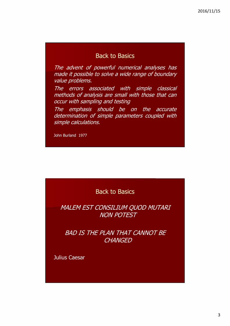
The advent of powerful numerical analyses hasmade it possible to solve a wide range of boundaryvalue problems.The errors associated with simple classicalmethods of analysis are small with those that canoccur with sampling and testingThe emphasis should be on the accuratedetermination of simple parameters coupled withsimple calculations.
John Burland 1977
Back to Basics
MALEM EST CONSILIUM QUOD MUTARI NON POTEST
BAD IS THE PLAN THAT CANNOT BE CHANGED
Julius Caesar
2016/11/15
4
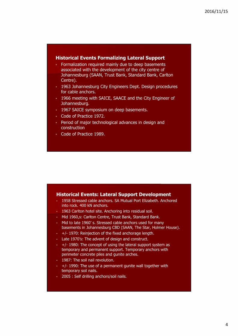
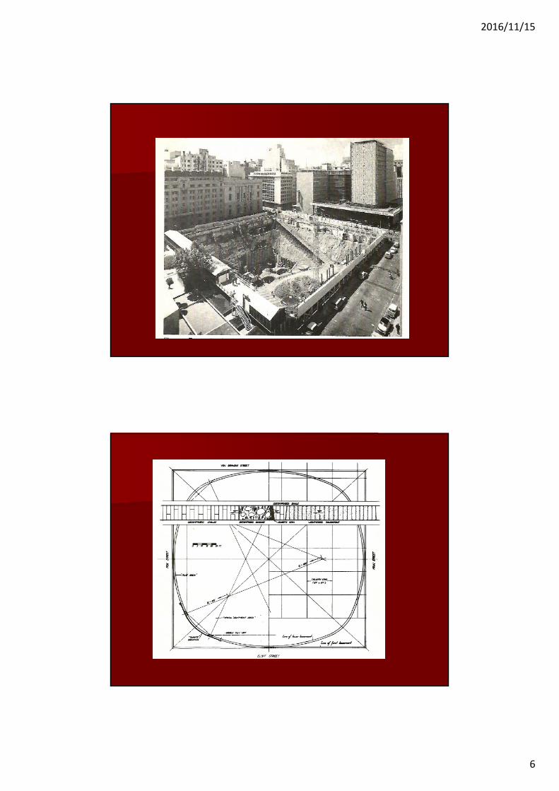
Historical Events Formalizing Lateral Support• Formalization required mainly due to deep basements
associated with the development of the city centre of Johannesburg (SAAN, Trust Bank, Standard Bank, Carlton Centre).
• 1963 Johannesburg City Engineers Dept. Design procedures for cable anchors.
• 1966 meeting with SAICE, SAACE and the City Engineer of Johannesburg.
• 1967 SAICE symposium on deep basements. • Code of Practice 1972.• Period of major technological advances in design and
construction• Code of Practice 1989.
Historical Events: Lateral Support Development• 1958 Stressed cable anchors. SA Mutual Port Elizabeth. Anchored
into rock. 400 kN anchors.• 1963 Carlton hotel site. Anchoring into residual soil. • Mid 1960,s: Carlton Centre, Trust Bank, Standard Bank.• Mid to late 1960’ s. Stressed cable anchors used for many
basements in Johannesburg CBD (SAAN, The Star, Holmer House).• +/- 1970: Reinjection of the fixed anchorage length.• Late 1970’s: The advent of design and construct.• +/- 1980: The concept of using the lateral support system as
temporary and permanent support. Temporary anchors with perimeter concrete piles and gunite arches.
• 1987: The soil nail revolution.• +/- 1990: The use of a permanent gunite wall together with
temporary soil nails.• 2005 : Self drilling anchors/soil nails.
2016/11/15
5
2016/11/15
6
2016/11/15
7
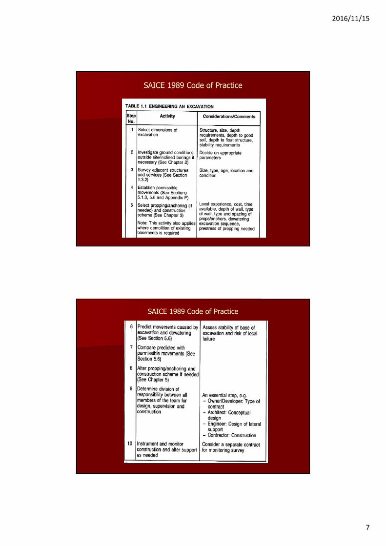
SAICE 1989 Code of Practice
SAICE 1989 Code of Practice
2016/11/15
8
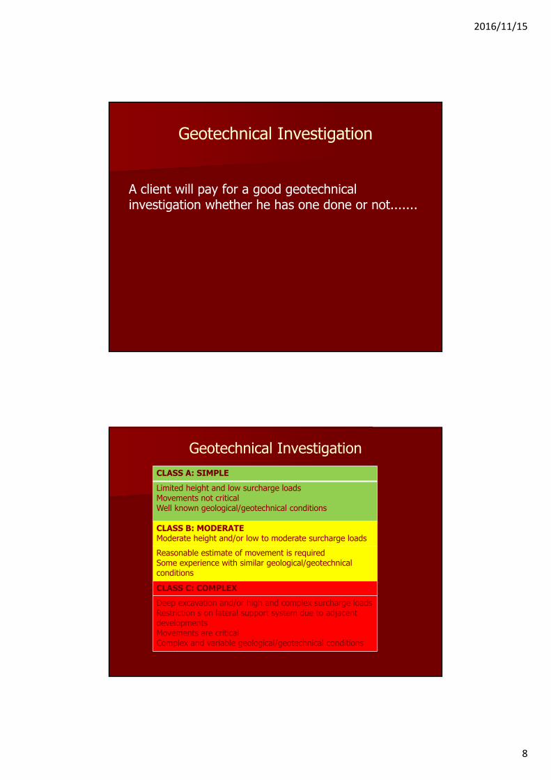
Geotechnical Investigation
A client will pay for a good geotechnical investigation whether he has one done or not.......
Geotechnical InvestigationCLASS A: SIMPLELimited height and low surcharge loadsMovements not criticalWell known geological/geotechnical conditions
CLASS B: MODERATEModerate height and/or low to moderate surcharge loadsReasonable estimate of movement is requiredSome experience with similar geological/geotechnical conditions
CLASS C: COMPLEXDeep excavation and/or high and complex surcharge loadsRestriction s on lateral support system due to adjacent developmentsMovements are criticalComplex and variable geological/geotechnical conditions

2016/11/15
9
Geotechnical Investigation
Class ASimple
Class BModerate
Class CComplex
Good description of the soil profile for full depthTrial holes/test pits to the full depth of excavation.Basic laboratory tests
Good description of the soil profile for full depthTrial holes and boreholes.Strength tests.
Trial holes and boreholes with in situ tests.Good description of the geological conditions and the soil and rock profile.Assessment of geological/geotechnical conditions outside the site boundaries.Strength and/or compressibility tests.Special in situ tests.
Geotechnical Parameters
Design for Stability
• Effective strength parameters • Peak or Residual. Structure of residual
soil. Relic joints slickensides.• The cohesion conundrum

2016/11/15
10
Geotechnical Parameters
Laboratory Testing for Shear Strength Parameters
• Triaxial • Shear Box• The effects of testing procedures
2016/11/15
11
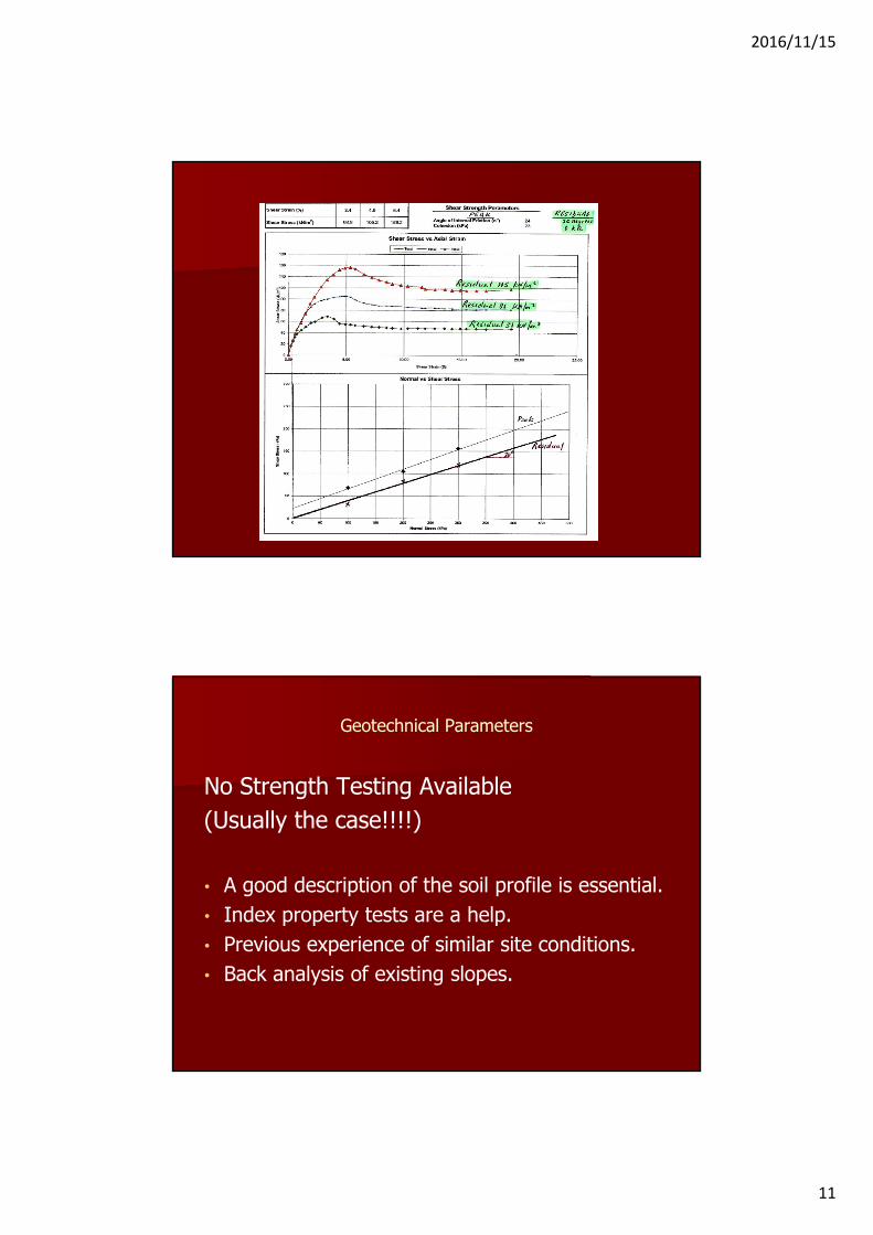
Geotechnical Parameters
No Strength Testing Available(Usually the case!!!!)
• A good description of the soil profile is essential.• Index property tests are a help.• Previous experience of similar site conditions.• Back analysis of existing slopes.
2016/11/15
12
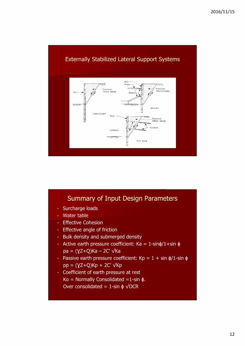
Externally Stabilized Lateral Support Systems
Summary of Input Design Parameters• Surcharge loads• Water table• Effective Cohesion• Effective angle of friction • Bulk density and submerged density• Active earth pressure coefficient: Ka = 1-sinϕ/1+sin ϕ
pa = (ƔZ+Q)Ka – 2C’ √Ka• Passive earth pressure coefficient: Kp = 1 + sin ϕ/1-sin ϕ
pp = (ƔZ+Q)Kp + 2C’ √Kp• Coefficient of earth pressure at rest
Ko = Normally Consolidated =1-sin ϕ. Over consolidated = 1-sin ϕ √OCR
2016/11/15
13
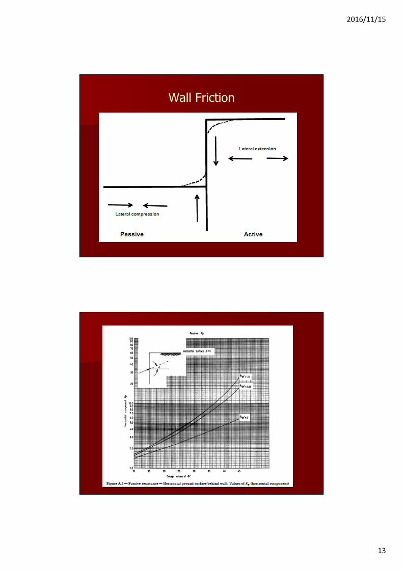
Wall Friction
2016/11/15
14
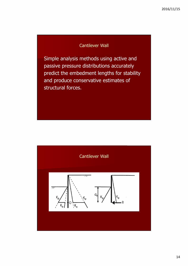
Cantilever Wall
Simple analysis methods using active andpassive pressure distributions accuratelypredict the embedment lengths for stabilityand produce conservative estimates ofstructural forces.
Cantilever Wall
2016/11/15
15
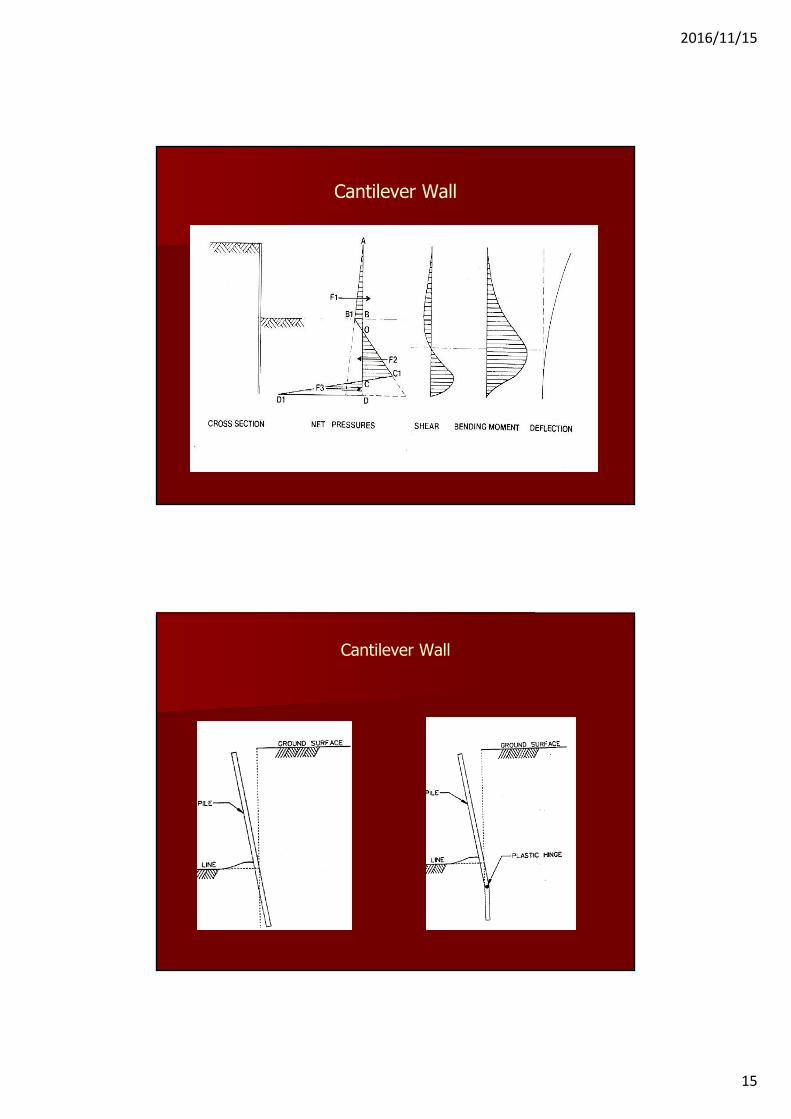
Cantilever Wall
Cantilever Wall

2016/11/15
16
Cantilever Wall
Wall Stability. Moments about the Toe
1. Factor of safety on passive resistance 2. Factor of safety on net passive resistance3. Methods 1 and 2 with a factor of safety
on strength4. The use of a multiplying factor
Cantilever Wall. Stability
2016/11/15
17
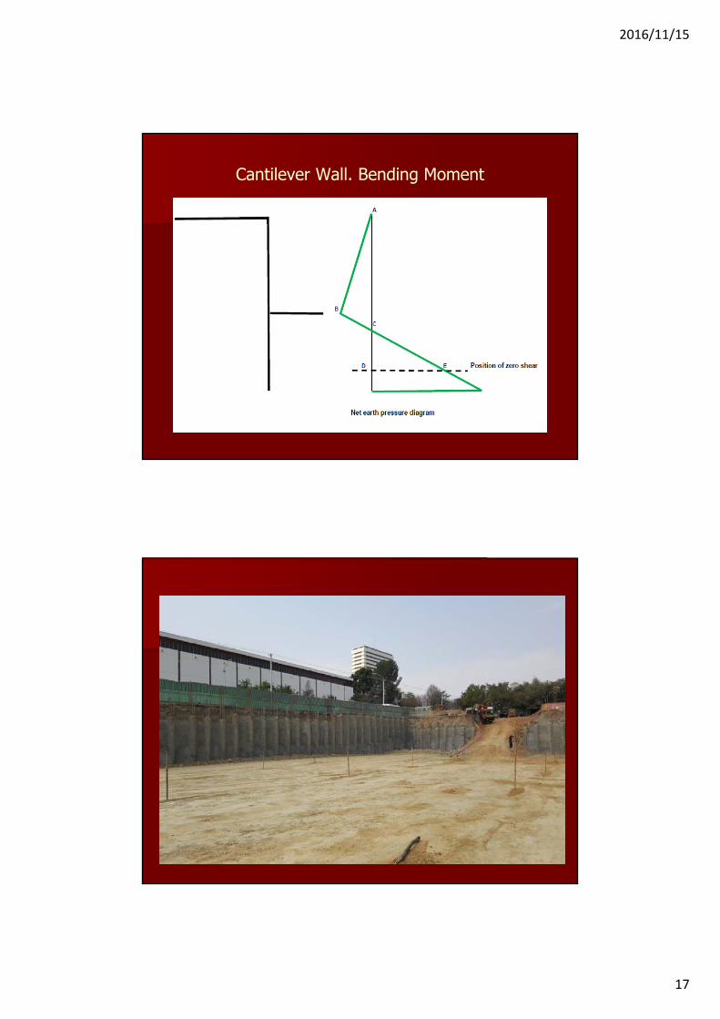
Cantilever Wall. Bending Moment
2016/11/15
18
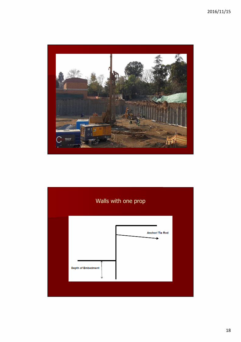
Walls with one prop
2016/11/15
19
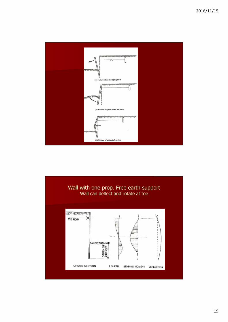
Wall with one prop. Free earth supportWall can deflect and rotate at toe

2016/11/15
20
Wall with One Prop. Free Earth Support
STABILITYSimple limit equilibrium methods of analysisusing Ka and Kp give an acceptable depth of embedment.
Moments of earth pressure about the anchor/prop
Active and passive pressure Net active and passive pressure
2016/11/15
21
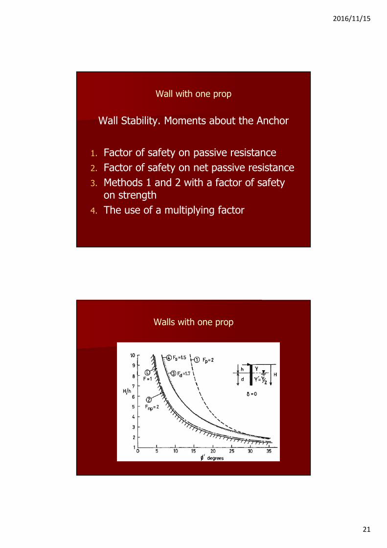
Wall with one prop
Wall Stability. Moments about the Anchor
1. Factor of safety on passive resistance 2. Factor of safety on net passive resistance3. Methods 1 and 2 with a factor of safety
on strength4. The use of a multiplying factor
Walls with one prop

2016/11/15
22
Anchor force
ANCHOR FREE LENGTH

2016/11/15
23
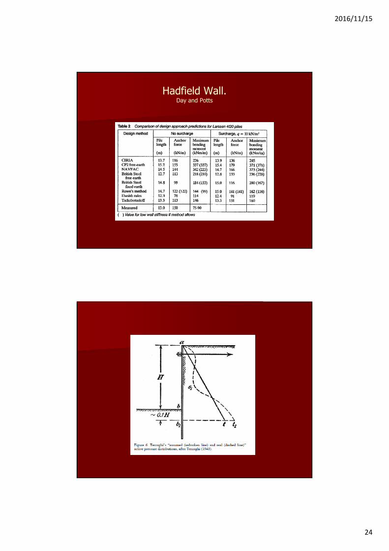
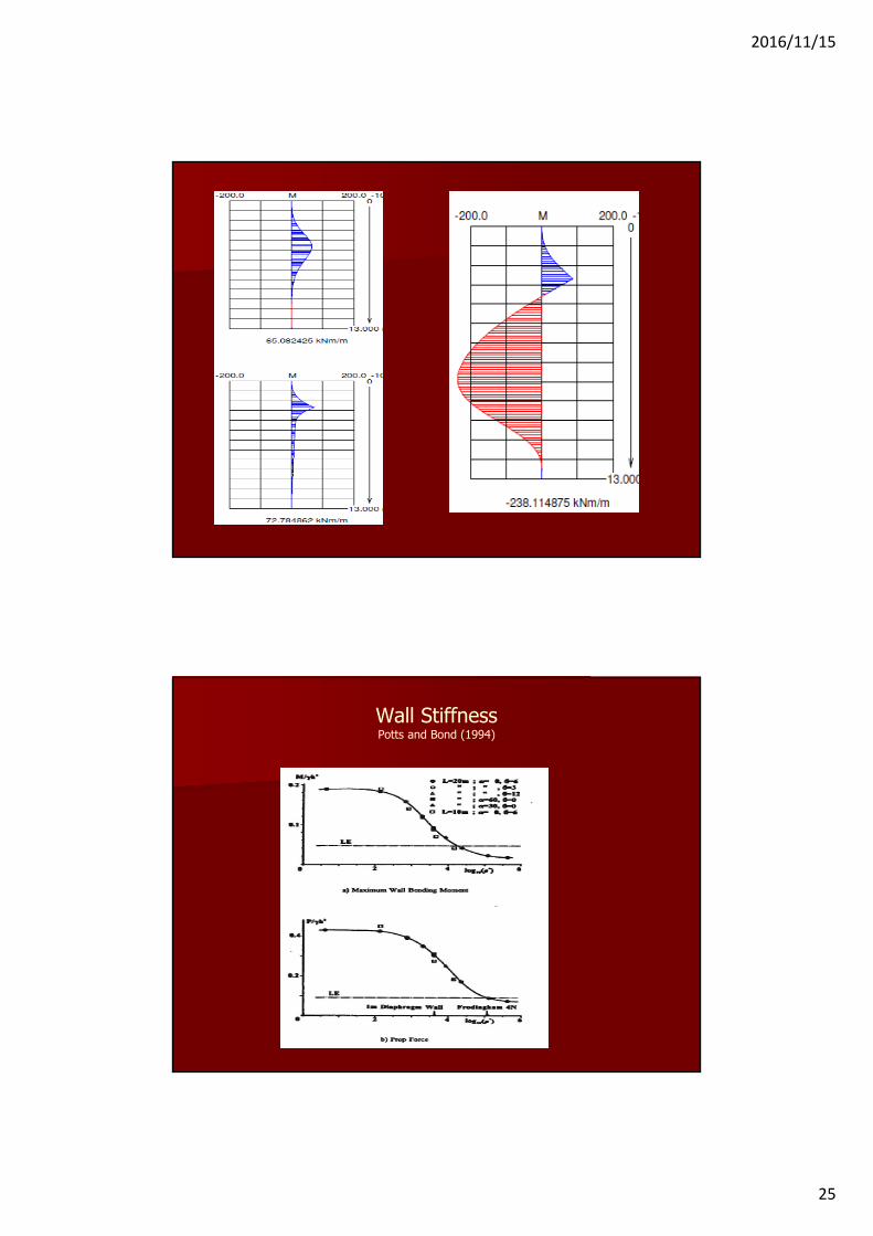
Bending MomentsEarth pressure at working conditions difficult to predictCalculated for earth pressure at limiting equilibriumWall stiffness an important parameter. Likely to be an over prediction for walls of low stiffness.
Hadfield Wall.Day and Potts
2016/11/15
24
Hadfield Wall.Day and Potts
2016/11/15
25
Wall StiffnessPotts and Bond (1994)
2016/11/15
26
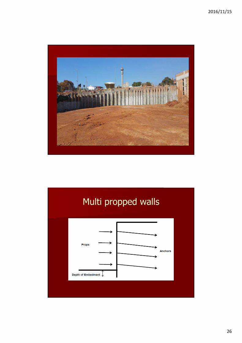
Multi propped walls

2016/11/15
27
Multi propped wallsMain Calculations• Anchor/prop loads required for stability• Magnitude and distribution of bending moments
Complex soil structure interaction problem. Dependant mainly on:• Type of soil (strength and stiffness)• Type and sequence of construction• Stiffness of the structure
Simple/limit equilibrium methods of analysis are based on certain theoretical considerations together with empirical procedures. In many cases the accuracy of these methods needs to be treated with caution.
Analyses must be carried out for all stages of construction to determine the maximum anchor forces/prop loads and bending moments
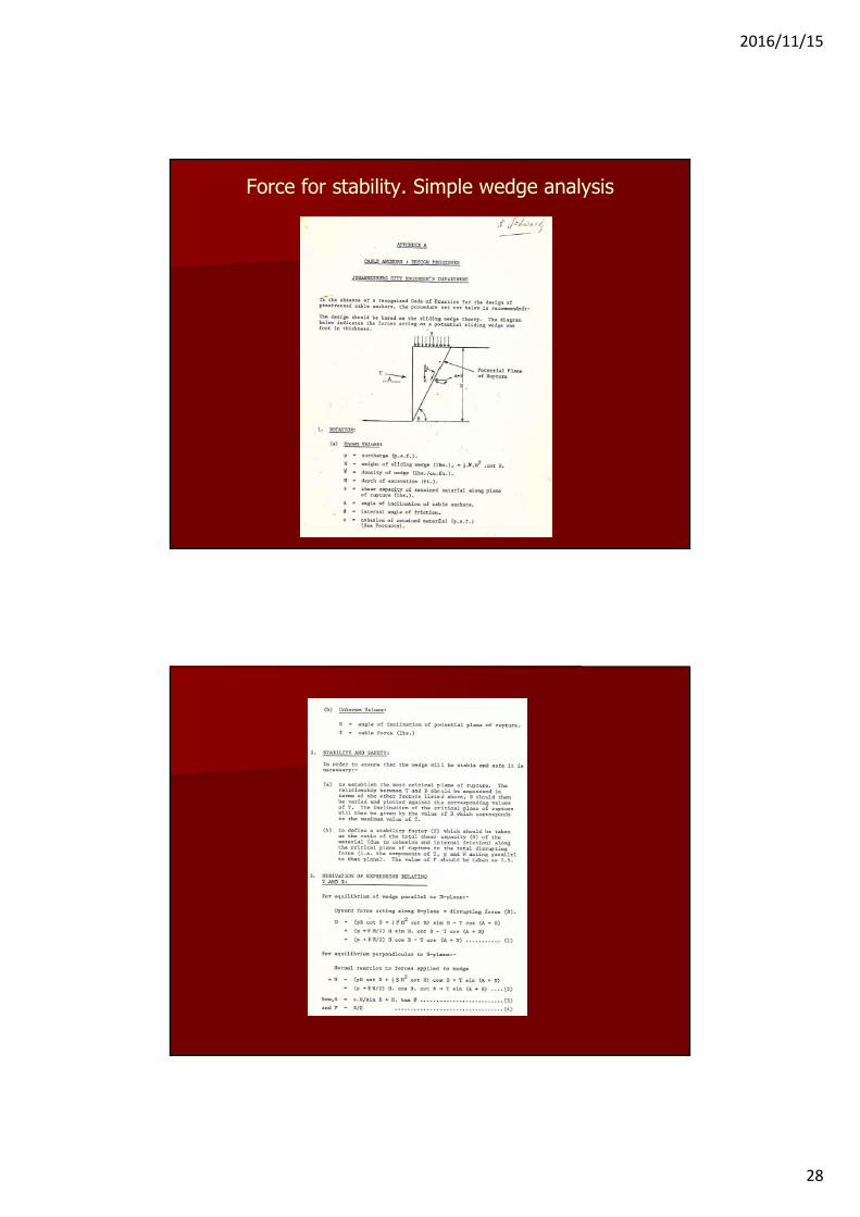
Force for stability• Pecks diagrams.• Assume an earth pressure distribution.
Ka to Ko depending on an assessment of wall stiffness and wall movement. Kp if applicable.
• Slope stability analyses (single wedge, multi wedge, log spiral, compound failure surfaces).
2016/11/15
28
Force for stability. Simple wedge analysis

2016/11/15
29

2016/11/15
30
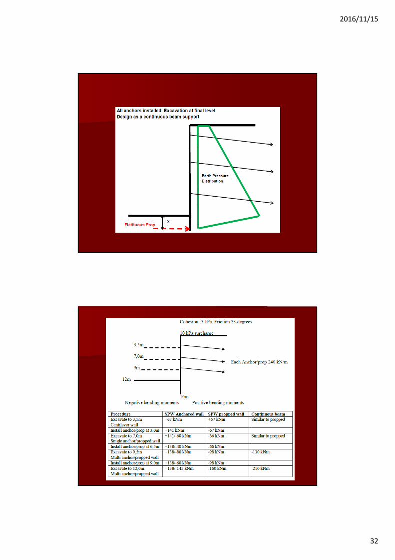
Bending moments simple limit equilibrium
2016/11/15
31
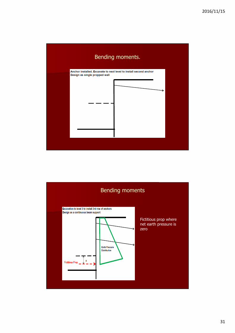
Bending moments.
Bending moments
Fictitious prop where net earth pressure is zero
2016/11/15
32

2016/11/15
33
Anchor free length
JHB CED Design ProcedureThe anchors should extend deeply enough so as to ensure that no surface which passes behind the points of anchorage has a factor of safety of less than 1,5 calculated on the strength of the retained material
Anchor free length
2016/11/15
34
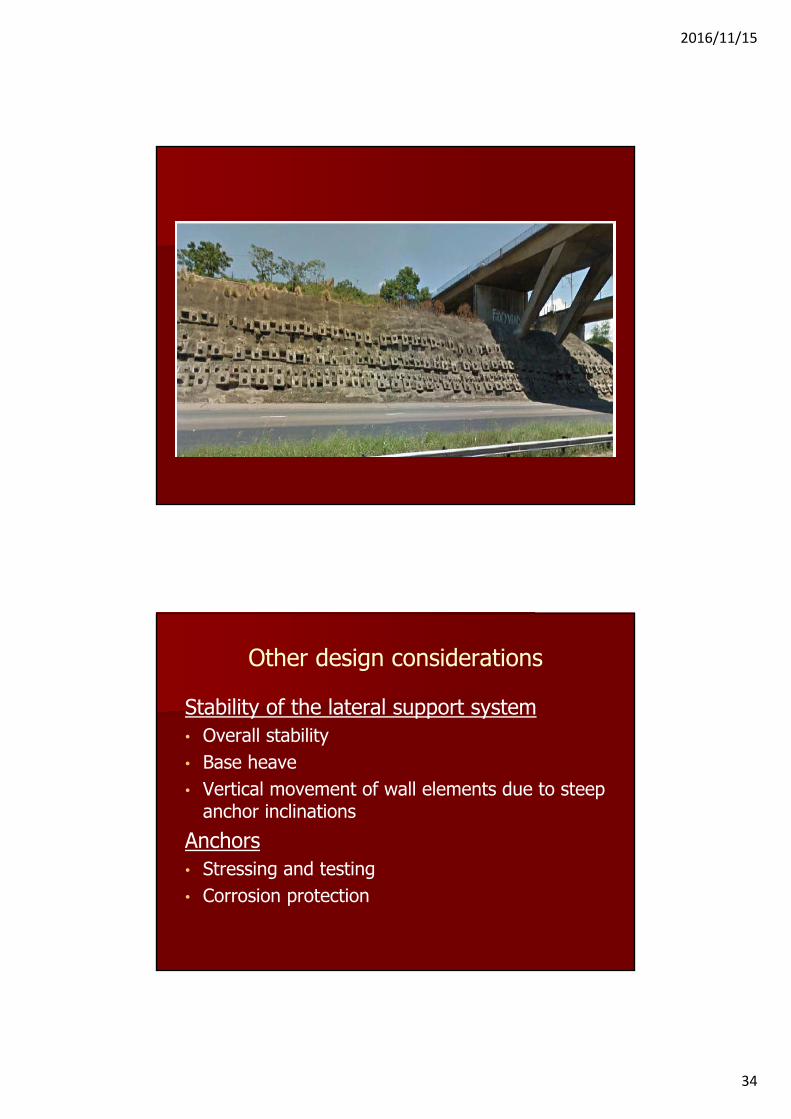
Other design considerations
Stability of the lateral support system• Overall stability• Base heave• Vertical movement of wall elements due to steep
anchor inclinationsAnchors• Stressing and testing• Corrosion protection

2016/11/15
35
Anchors
AnchorsWorking capacity controlled by COP requirements for stressing.Temporary: 80% of yield at 125% of working loadPermanent: 80% of yield at 150% of working load
Strand: 265 kN. Temporary: 170 kN/strandPermanent: 140 kN/strand
Threaded bars: 550 MPa to 1050 MPaSelf drilling systems: Yield 180 kN to 1600 kN

2016/11/15
36

2016/11/15
37
2016/11/15
38
2016/11/15
39
2016/11/15
40
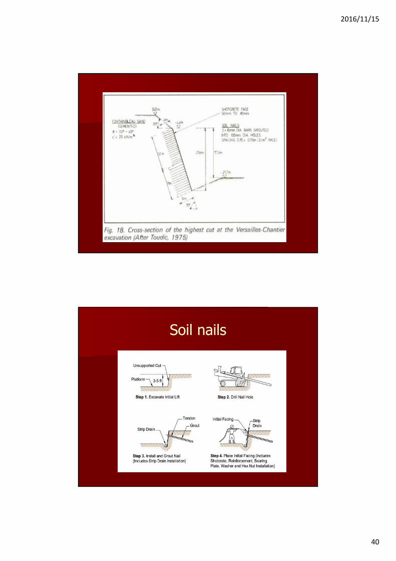
Soil nails
2016/11/15
41
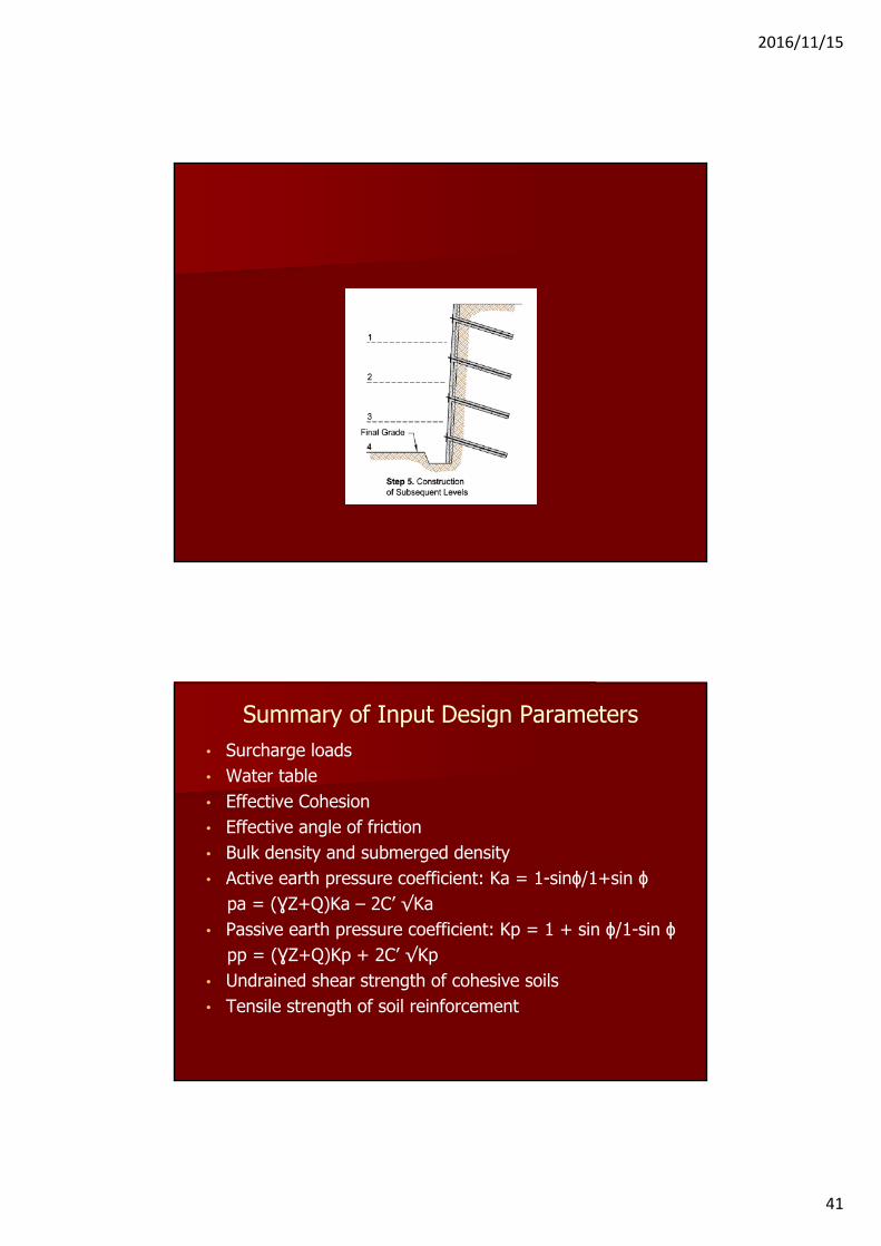
Summary of Input Design Parameters• Surcharge loads• Water table• Effective Cohesion• Effective angle of friction • Bulk density and submerged density• Active earth pressure coefficient: Ka = 1-sinϕ/1+sin ϕ
pa = (ƔZ+Q)Ka – 2C’ √Ka• Passive earth pressure coefficient: Kp = 1 + sin ϕ/1-sin ϕ
pp = (ƔZ+Q)Kp + 2C’ √Kp• Undrained shear strength of cohesive soils• Tensile strength of soil reinforcement

2016/11/15
42
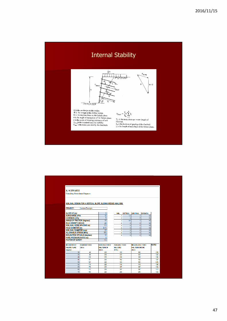
Internal Stability
2016/11/15
43
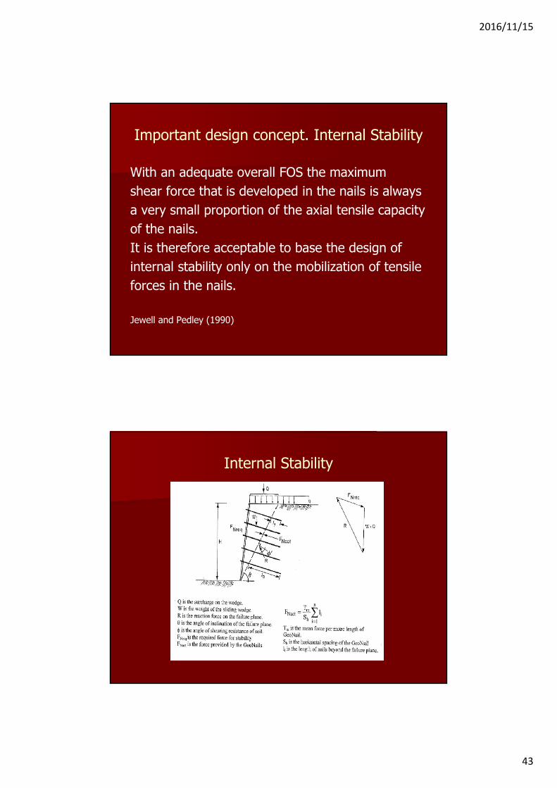
Important design concept. Internal Stability
With an adequate overall FOS the maximumshear force that is developed in the nails is alwaysa very small proportion of the axial tensile capacityof the nails.It is therefore acceptable to base the design ofinternal stability only on the mobilization of tensileforces in the nails.
Jewell and Pedley (1990)
Internal Stability

2016/11/15
44
Soil nails
Grout/soil bond
Classic conceptT = c’ + δ’r tanφ’δ'r = K δ’v
Implies that there is a linear increase in bond with depth

2016/11/15
45
Grout/soil bond
Grout/soil bond
2016/11/15
46
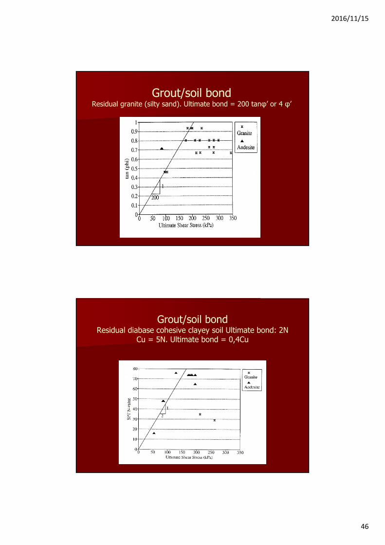
Grout/soil bondResidual granite (silty sand). Ultimate bond = 200 tanφ’ or 4 φ’
Grout/soil bondResidual diabase cohesive clayey soil Ultimate bond: 2N
Cu = 5N. Ultimate bond = 0,4Cu
2016/11/15
47
Internal Stability
2016/11/15
48
Soil Nail Applications• Lateral support for excavations of limited height and
where moderate movements can be tolerated.• Stabilization of road and railway cuts.• Stabilization of cuts for road widening.• Stabilization of abutment fills for road widening.• Repair and reconstruction of existing retaining walls.• Hybrid walls for road widening together with other soil
reinforcement systems.
2016/11/15
49
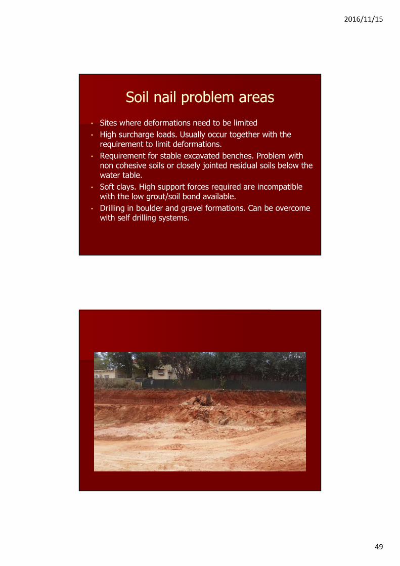
Soil nail problem areas• Sites where deformations need to be limited• High surcharge loads. Usually occur together with the
requirement to limit deformations.• Requirement for stable excavated benches. Problem with
non cohesive soils or closely jointed residual soils below the water table.
• Soft clays. High support forces required are incompatible with the low grout/soil bond available.
• Drilling in boulder and gravel formations. Can be overcome with self drilling systems.

2016/11/15
50
2016/11/15
51
2016/11/15
52
2016/11/15
53

2016/11/15
54

2016/11/15
55
2016/11/15
56

2016/11/15
57
2016/11/15
58
Additional Essential Design Processes
ENGINEERING JUDGEMENT
The application of sound “Judgement” is the Heart of good geotechnical engineering.
Gut feel based on the analysis of data is a valid part of good geotechnical engineering practice.
Engineering judgement involvesassembling all the data you can, doing allthe calculations you can and then on thebasis of a good bottle of brandy and agood nights sleep , making your decision.J. E. Jennings
2016/11/15
59
Engineering Judgement
Sub- surface engineering has developed largely on the basis of case histories tempered with scientific knowledge. If we ever reach the situation in which we believe that engineering science can replace experience and judgement based on such experience, disaster is not far away.
John Burland 1975
Additional Essential Design ProcessesThe Observational Method of Design
Continuous managed and integrated process of construction control, monitoring and review to enable modifications to be incorporated during construction if necessary.
The objective is to apply the most appropriate design and construction procedures without compromising safety.
The construction phase essentially becomes an extension of the design phase
2016/11/15
60
Failures Near Failures and Movements
No excavation can be made without causing some movement of the surrounding ground1989 Lateral Support COP
Stress is an abstract concept.Strain is the physical realityJohn Burland
Failures Near Failures and Movements
Correctly applied limit equilibrium analyses are acceptable in terms of the analysis of overall stability of a retaining system.
Failures defined as the overall collapse of the lateral support system are rare.

2016/11/15
61
Failures Near Failures and MovementsWith limit equilibrium analysis procedures it is not possible to predict movements.
Predictions are based on experience of excavations in similar conditions and general rules of thumb.
Failures Near Failures and Movements
Rules of thumbActive support: 0,1% to 0,2% of the heightPassive support: 0,15% to 0,3% of the height
Unfortunately mother nature does not always play by the rules
The role of advanced numerical analyses
2016/11/15
62
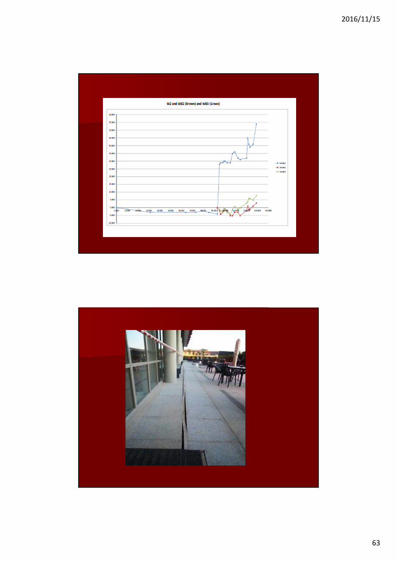
2016/11/15
63
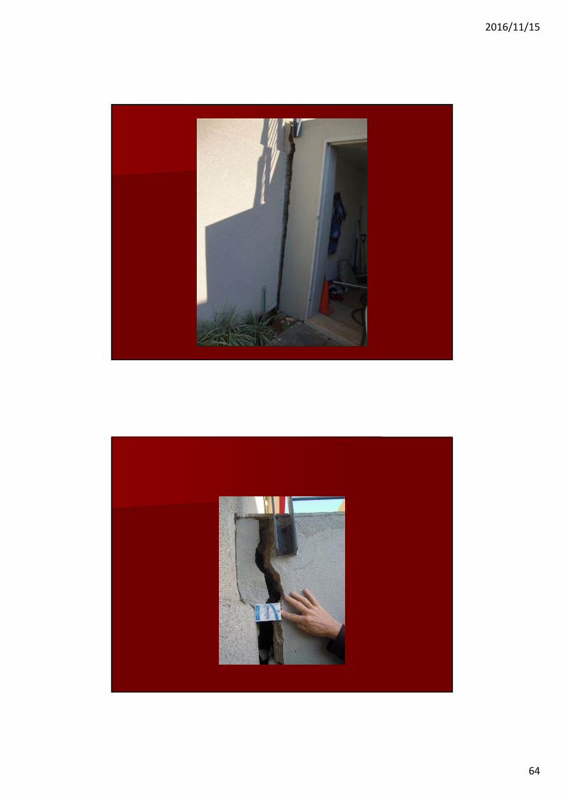
2016/11/15
64

2016/11/15
65
2016/11/15
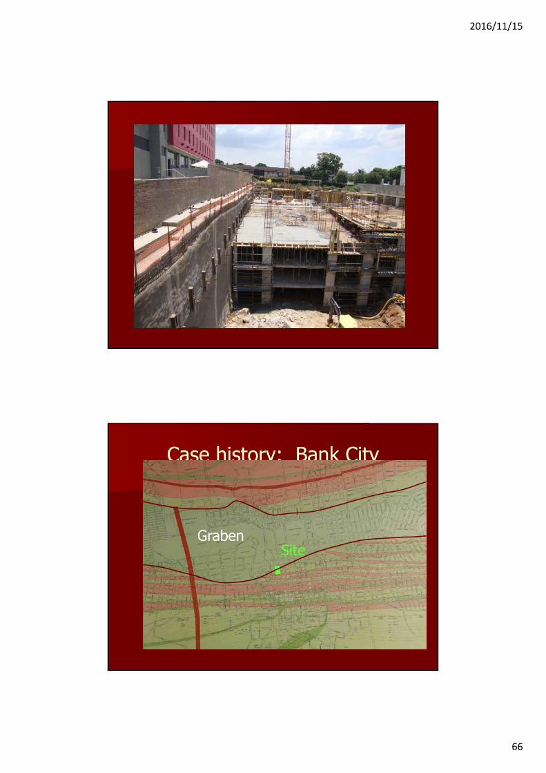
66
Case history: Bank City
GrabenSite
2016/11/15
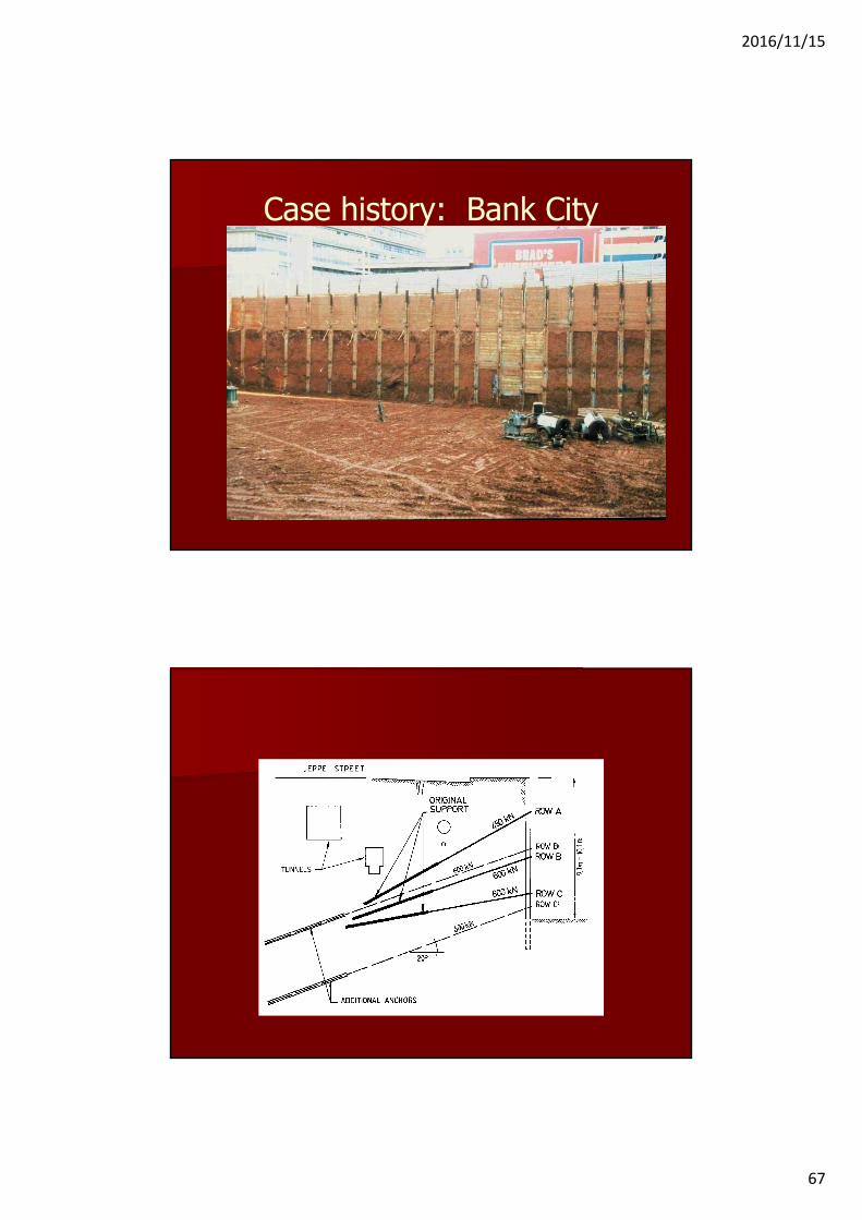
67
Case history: Bank City

2016/11/15
68
Case history: Bank CityM
ovem
ent
(mm
)
Maximum
Average
Case history: Bank City

2016/11/15
69
Case history: Bank CityM
ovem
ent
(mm
)
Str
ess
B’
Str
ess
C’
Case history: Bank City

2016/11/15
70
Case history: Bank City
Case history: Bank City
Mov
emen
t (m
m)
Str
ess
B’
Str
ess
C’
2016/11/15
71
Failures Near Failures and MovementsMain Contributing Factors (Never a single Factor):• Inadequate geotechnical investigation leading to unforeseen
conditions.• Inadequate definition of surrounding site conditions.• Incorrect/optimistic design concept or design procedures.• Poor lateral support construction practice .• Localized small failures or fall outs during excavation.• Unauthorized over excavation by the earthworks contractor.• Vibrations due to uncontrolled blasting. • Not adopting or the incorrect application of the observational
method of design.• Unreasonable pressure from the client and/or the project
manager.
If you can keep your head when all about youare losing theirs and blaming it on you,If you can trust yourself when all men doubt you,but make allowance for their doubting too;
If.......
If you can meet with Triumph and DisasterAnd treat those two imposters just the same
If....
And which is more you will be a Man, my Son
Rudyard Kipling
2016/11/15
72
Lateral Support Back to BasicsWhere to now???Experience has shown that our engineers have the capability to design lateral support for deep and complex excavations.
Explore the benefits of numerical analyses.
Improve the information provided for design.• Geotechnical investigation• Structural and layout details
Full scale monitoring of excavations.