launch pack group i gland - rst · differences between new group i gland and existing ham existing...
TRANSCRIPT

Launch Pack Group I Gland

Key Message
The new Group 1 gland is an addition to the already successful HAM conduit glands. It is of a higher specification and has been designed to meet the requirements not already covered by the existing HAM gland.
The new range includes
Group 1 Exd conduit gland Group 1 Exd universal gland Group 1 Exd conduit elbows
In this launch document you will find the following
Features and benefits Comparison tables between the new and the existing range Examples of possible applications Pricing information Technical datasheets Certifications Instruction sheets


ComparisonCharts
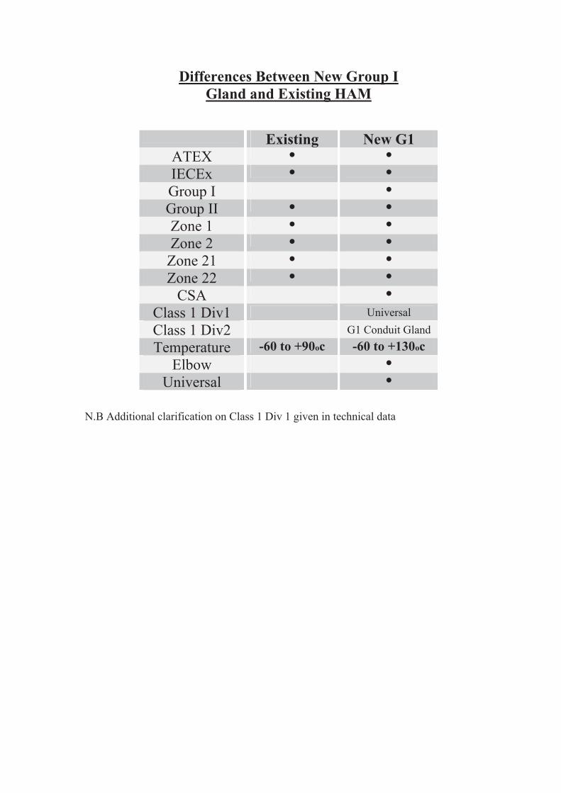
Differences Between New Group IGland and Existing HAM
Existing New G1ATEX ● ●
IECEx ● ●
Group I ●
Group II ● ●
Zone 1 ● ●
Zone 2 ● ●
Zone 21 ● ●
Zone 22 ● ●
CSA ●
Class 1 Div1 Universal
Class 1 Div2 G1 Conduit Gland
Temperature -60 to +90oc -60 to +130oc
Elbow ●
Universal ●
N.B Additional clarification on Class 1 Div 1 given in technical data

Data Comparison Sheet for New G1 Gland v Existing HAM
Working
Length (mm)
Amount of
CoresIncrease
Diameter over
cores (mm)Increase Weight (g)
HAM0304 58 6 8.9 218
HAM0304G1 50.0 9 50% 10.5 18.0% 188.0
HAM0404 58.0 10 11.0 213.0
HAM0404G1 50.0 15 50% 13.0 18.2% 183.0
HAM0505 62.0 21 16.2 259.0
HAM0505G1 50.0 28 33% 17.9 10.5% 236.0
HAM0606 67.0 42 21.9 468.0
HAM0606G1 50.0 50 19% 24.0 9.6% 323.0
HAM0707 73.0 60 26.3 854.0
HAM0707G1 57.0 75 25% 32.0 21.7% 491.0
HAM0808 84.0 80 37.1 1016.0
HAM0808G1 58.0 80 0% 37.5 1.1% 674.0
HAM0909 92.0 100 47.8 1590.0
HAM0909G1 70.0 100 0% 46.5 -2.7% 1067.0
Comparison Weights
0
200
400
600
800
1000
1200
1400
1600
1800
Size
We
igh
t (g
)
Existing HA
New G1
Existing HA 218 213.0 259 468.0 854.0 1016.0 1590.0
New G1 188 183.0 236 323.0 491.0 674.0 1067.0
M16 M20 M25 M32 M40 M50 M63

PossibleApplications

Applications
ng
Lifts
Conveyors
rocessontrol Mining
Trains
ControlPanels

TechnicalDatasheets

NEW HA GLAND AND CSA
Variations of flameproof gland
HA****G1 HA****U
HA****G1 is an equivalent gland to the existing Hawke HA gland but with added benefits.
It can only be used with flexible liquidtight conduits. Flexible liquidtight conduits cannot be used in Class I Div 1 installations. As such this gland is certified for Class l Div 2 installations only.
HA****U universal gland has a female thread and as such can be used with any conduit.
Thread variations are metric and NPT. As such rigid conduit can be screwed into the back of the gland. Rigid conduit is the only conduit allowed in Class l Div 1 installations. We will mark the female nut with the Class l Div 1 approval markings as required
All glands will be, by default marked with Class l Div 2. We will only supply nuts with Class l Div 1 when specifically requested.
Technical Data Sheet
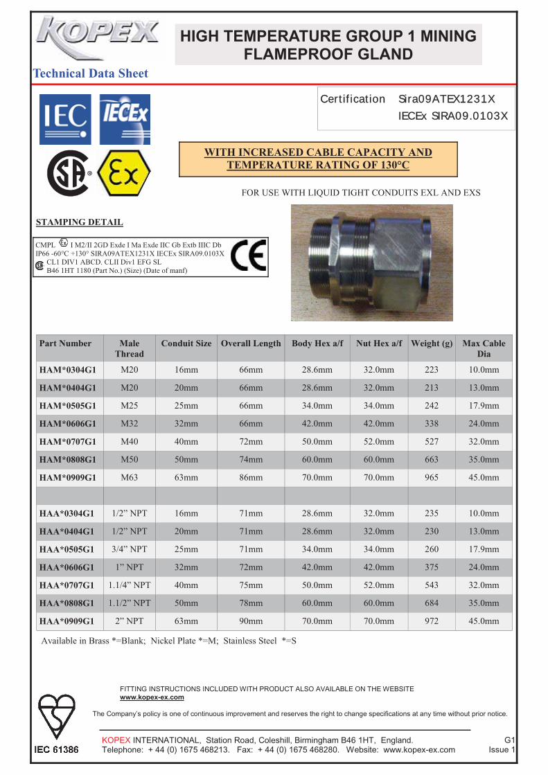
HIGH TEMPERATURE GROUP 1 MINING
FLAMEPROOF GLAND
KOPEX INTERNATIONAL, Station Road, Coleshill, Birmingham B46 1HT, England. Telephone: + 44 (0) 1675 468213. Fax: + 44 (0) 1675 468280. Website: www.kopex-ex.com
G1Issue 1
The Company’s policy is one of continuous improvement and reserves the right to change specifications at any time without prior notice.
FITTING INSTRUCTIONS INCLUDED WITH PRODUCT ALSO AVAILABLE ON THE WEBSITE www.kopex-ex.com
Certification Sira09ATEX1231X IECEx SIRA09.0103X
STAMPING DETAIL
Part Number Male Thread
Conduit Size Overall Length Body Hex a/f Nut Hex a/f Weight (g) Max Cable Dia
HAM*0304G1 M20 16mm 66mm 28.6mm 32.0mm 223 10.0mm
HAM*0404G1 M20 20mm 66mm 28.6mm 32.0mm 213 13.0mm
HAM*0505G1 M25 25mm 66mm 34.0mm 34.0mm 242 17.9mm
HAM*0606G1 M32 32mm 66mm 42.0mm 42.0mm 338 24.0mm
HAM*0707G1 M40 40mm 72mm 50.0mm 52.0mm 527 32.0mm
HAM*0808G1 M50 50mm 74mm 60.0mm 60.0mm 663 35.0mm
HAM*0909G1 M63 63mm 86mm 70.0mm 70.0mm 965 45.0mm
HAA*0304G1 1/2” NPT 16mm 71mm 28.6mm 32.0mm 235 10.0mm
HAA*0404G1 1/2” NPT 20mm 71mm 28.6mm 32.0mm 230 13.0mm
HAA*0505G1 3/4” NPT 25mm 71mm 34.0mm 34.0mm 260 17.9mm
HAA*0606G1 1” NPT 32mm 72mm 42.0mm 42.0mm 375 24.0mm
HAA*0707G1 1.1/4” NPT 40mm 75mm 50.0mm 52.0mm 543 32.0mm
HAA*0808G1 1.1/2” NPT 50mm 78mm 60.0mm 60.0mm 684 35.0mm
HAA*0909G1 2” NPT 63mm 90mm 70.0mm 70.0mm 972 45.0mm
Available in Brass *=Blank; Nickel Plate *=M; Stainless Steel *=S
FOR USE WITH LIQUID TIGHT CONDUITS EXL AND EXS
CMPL I M2/II 2GD Exde I Ma Exde IIC Gb Extb IIIC Db IP66 -60°C +130° SIRA09ATEX1231X IECEx SIRA09.0103X
CL1 DIV1 ABCD. CLII Div1 EFG SL B46 1HT 1180 (Part No.) (Size) (Date of manf)
WITH INCREASED CABLE CAPACITY AND TEMPERATURE RATING OF 130°C

Technical Data Sheet
HIGH TEMPERATURE GROUP 1 MINING
UNIVERSAL GLAND
KOPEX INTERNATIONAL, Station Road, Coleshill, Birmingham B46 1HT, England. Telephone: + 44 (0) 1675 468213. Fax: + 44 (0) 1675 468280. Website: www.kopex-ex.com
G1Issue 1
The Company’s policy is one of continuous improvement and reserves the right to change specifications at any time without prior notice.
FITTING INSTRUCTIONS INCLUDED WITH PRODUCT ALSO AVAILABLE ON THE WEBSITE www.kopex-ex.com
Certification Sira09ATEX1231X IECEx SIRA09.0103X
STAMPING DETAIL
Part Number Male Thread ‘A’
Female Thread ‘B’
Overall Length Body Hex a/f Nut Hex a/f Weight (g) Max Cable Dia
HAM*0403U M20 M16 72mm 28.6mm 32.0mm 319 10.0mm
HAM*0404U M20 M20 72mm 28.6mm 32.0mm 279 13.0mm
HAM*0505U M25 M25 72mm 34.0mm 34.0mm 357 17.9mm
HAM*0606U M32 M32 72mm 42.0mm 42.0mm 481 24.0mm
HAM*0707U M40 M40 75mm 50.0mm 52.0mm 643 32.0mm
HAM*0808U M50 M50 79mm 60.0mm 60.0mm 929 35.0mm
HAM*0909U M63 M63 90mm 70.0mm 70.0mm 1.466 45.0mm
HAA*0304U 1/2”NPT M16 77mm 28.6mm 32.0mm 10.0mm
HAA*0404U 1/2” NPT M20 77mm 28.6mm 32.0mm 13.0mm
HAA*0505U 3/4” NPT M25 77mm 34.0mm 34.0mm 17.9mm
HAA*0606U 1” NPT M32 77mm 42.0mm 42.0mm 24.0mm
HAA*0707U 1.1/4” NPT M40 80mm 50.0mm 52.0mm 32.0mm
HAA*0808U 1.1/2” NPT M50 84mm 60.0mm 60.0mm 35.0mm
HAA*0909U 2” NPT M63 95mm 70.0mm 70.0mm 45.0mm
Available in Brass *=Blank; Nickel Plate *=M; Stainless Steel *=S
FOR USE WITH LIQUID TIGHT CONDUITS EXL AND EXS
CMPL I M2/II 2GD Exde I Ma Exde IIC Gb Extb IIIC Db IP66 -60°C +130° SIRA09ATEX1231X IECEx SIRA09.0103X
CL1 DIV1 ABCD. CLII Div1 EFG SL B46 1HT 1180 (Part No.) (Size) (Date of manf)
WITH INCREASED CABLE CAPACITY AND TEMPERATURE RATING OF 130°C
Mal
e T
hrea
d ‘A
’
Fem
ale
Thr
ead
‘B’
Approved for Groups I&II Exd I&IIC Exe I&II Extb IIIC

KOPEX INTERNATIONAL , Station Road, Coleshill, Birmingham B46 1HT, England. Telephone: + 44 (0) 1675 468213. Fax: + 44 (0) 1675 468280. Website: www.kopex-ex.com
Page 1
90° Flameproof Gland
Exd I&IIC Exe I&II Extb IIIC CSA Class I Div 1 ABCD; Class II Div 1 EFG Approved for Gas and Dust
FLEXIBLE CONDUIT GLAND SELECTION TABLE
Size Ref (conduit size)
Kopex Ref Gland Body 90° Elbow Male Thread Metric NPT
Max Dia. Over Cores
Max Dia. Over
Single Core
Max No. Of Cores
Overall Length
AcrossFlats
AcrossCorners
AcrossFlats Conduit Size
16 / 3/8“ HAM*0304E
28.6 31.0 32.0 16 mmM20
10.5 10.0 9 90.0 HAA*0304E 1/2”
20 / 1/2“ HAM*0404E
28.6 31.0 32.0 20mm M20
13.0 13.0 15 90.0 HAA*0404E 1/2"
25 / 3/4“ HAM*0505E
34.0 37.0 34.0
34.9 SS 25mm
M25 17.9 17.9 28 104.0
HAA*0505E 3/4"
32 / 1“ HAM*0606E
42.0 45.0 42.0
42.4 SS 32mm
M32 24.0 20.0 50 114.0
HAA*0606E 1"
40 / 1,1/4“ HAM*0707E
50.0 54.0 52.0 40mm M40
32.0 32.0 75 130.0 HAA*0707E 1,1/4"
50 / 1,1/2“ HAM*0808E
60.0 64.0 60.0 50mm M50
35.0 35.0 80 146.0 HAA*0808E 1,1/2"
63 / 2“ HAM*0909E
70.0 76.0 70.0
69.8 SS 63mm
M63 45.0 45.0 100 169.0
HAA*0909E 2"
Manufactured in Brass, Nickel Plated Brass and Stainless Steel 316 HAM Brass HAMM Nickel Plated HAMS Stainless Steel
For use in Groups I, II & III Zones 1, 2, 21 & 22
Properties IP Rating IP66 Operating Temperature -60° to +130°C Approvals Carries full Sira Certification to the requirements of the Standards: IEC60097-0:2007 Ed 5 IEC60079-1:2007 Ed 6 IEC60079-7:2007 Ed 4 IEC60079-31:2008 Ed 1 EN60079-0:2009 EN60079-1:2007 EN60079-7:2007 EN60079-31:2008 Certification Sira09ATEX1231X IECEx SIRA09.0103X
Gland comes complete with two part epoxy putty, gloves and fitting instructions. Putty can be obtained separately if required in 50g and 75g sizes. Part codes EXEP/50 & EXEP/75
Overall Length

MFC �SEALING �TECHNOLOGY �CO.,Ltd. PHYSICAL �PROPERTY �TEST �DATA
ISSUING �DATE:09/03/17 =============================================================================================== REPORT �NO. �:A-MFC-S7009 COMPOUND �NO. �:S7009 MATERIAL �:SIL HARDNESS �:70 COLOR �:RED SPECIFICATION �:ASTM �D2000 �M7GE �705 �A19 �B37 �EA14 �EO16 �EO36 �F19 REMARK �:
=============================================================================================== ----------------------------------------------- ---------------------- --------- --------
CHARACTERISTICS� REQUIREMENTS� RESULT� DECISION ----------------------------------------------- ---------------------- --------- ---- -- 705 �PHYSICAL �PROPERTIES,23
--------------------------- HARDNESS, �ASTM �D2240, �TYPE A � 70.00 �+/- 5.00 72.00 �PTS� OK HARDNESS, �ASTM �D2240, �TYPE M � 70.00 �+/- 5.00 74.00 �MPA� OK TENSILE �STRENGTH, �ASTM �D412, �MIN� 5.00 �MIN� 7.12 �MPA� OK ULTIMATE �ELONGATION, �ASTM �D412, �MIN� 150.00 �MIN� 263.00 % � OK SPECIFIC �GRAVITY, �ASTM �D297� 1.30 �---- OK
----------------------------------------------- ---------------------- --------------- -- A19 �HEAT �RESISTANCE, �ASTM �D573, �70H,225
---------------------------------------- CHANGE �IN �HARDNESS� 10.00 �MAX� 3.10 �PTS� OK CHANGE �IN �TENSILE �STRENGTH� -25.00 �MIN� 9.20 % � OK CHANGE �IN �ULTIMATE �ELONGATION� -30.00 �MIN� -27.00 % � OK
----------------------------------------------- ---------------------- --------------- -- B37 �COMPRESSION �SET, �ASTM �D395, �22H, M �
METHOD �B, �PLIED,175 ----------------------------------------- COMPRESSION �SET� 30.00 �MAX� 11.00 % � OK
----------------------------------------------- ---------------------- --------------- -- EA14 �WATER �RESISTANCE, �ASTM �D471, �70H�
,100 ----------------------------------------- CHANGE �IN �HARDNESS� 0.00 �+/- 5.00 0.10 �PTS� OK CHANGE �IN �TENSILE �STRENGTH� 5.00 % � OK CHANGE �IN �ULTIMATE �ELONGATION� -17.00 % � OK CHANGE �IN �VOLUME� 0.00 �+/- 5.00 0.50 % � OK
----------------------------------------------- ---------------------- --------------- -- EO16 �OIL �RESISTANCE, �ASTM �D471, �ASTM �OI�
IL �NO.1, �70H,150 ----------------------------------------- CHANGE �IN �HARDNESS� -5.00 �+/- 5.00 -4.30 �PTS� OK CHANGE �IN �TENSILE �STRENGTH� -20.00 �MIN� 13.00 % � OK CHANGE �IN �ULTIMATE �ELONGATION� -20.00 �MIN� -11.00 % � OK CHANGE �IN �VOLUME� 7.50 �+/- 7.50 5.40 % � OK
----------------------------------------------- ---------------------- --------------- -- EO36 �OIL �RESISTANCE, �ASTM �D471, �ASTM �OI�
IL �IRM �903, �70H,150 ----------------------------------------- CHANGE �IN �HARDNESS� -40.00 �MIN� -16.00 �PTS� OK CHANGE �IN �TENSILE �STRENGTH� -23.00 % � OK CHANGE �IN �ULTIMATE �ELONGATION� -5.80 % � OK CHANGE �IN �VOLUME� 60.00 �MAX� 36.00 % � OK
----------------------------------------------- ---------------------- --------------- -- F19 �LOW-TEMP. �RESISTANCE, �ASTM �D2137,�

METHOD �A, 3 �MIN,-60 ----------------------------------------- NONBRITTLE �AFTER 3 �MIN� PASS� OK
MFC �SEALING �TECHNOLOGY �CO.,Ltd. PHYSICAL �PROPERTY �TEST �DATA
ISSUING �DATE:09/03/17 =============================================================================================== REPORT �NO. �:A-MFC-S7009�COMPOUND �NO. �:S7009�MATERIAL �:SIL�HARDNESS �:70�COLOR �:RED�SPECIFICATION �:ASTM �D2000 �M7GE �705 �A19 �B37 �EA14 �EO16 �EO36 �F19�REMARK �:�
=============================================================================================== ----------------------------------------------- ---------------------- --------- --------
CHARACTERISTICS� REQUIREMENTS� RESULT� DECISION ----------------------------------------------- ---------------------- --------- ---- -- ----------------------------------------------- ---------------------- --------------- --
=============================================================================================== Note:1.The �MFC �data �are �obtained �by �testing �slab/button �and �are �for �reference �only.
2.Our �compound �can �meet �above �ASTM �D2000 �required.
APPROVED:ALVIN �CHAN �PRODUCE:Kelly VERSION: �1.70 �DATE:09/03/16

TechnicalDatasheets
Epoxy Putty

Kopex International, Station Road, Coleshill, Birmingham B46 1HT Telephone +44 (0) 1675 458213 Fax +44 (0) 1675 468280 Website www.kopex-ex.com
EXEP Epoxy Putty Technical Data Sheet
Supply
EXEP Epoxy putty is supplied in either 50g or 75 packs. Part codes are EXEP/50 and EXEP/75
Description
EXEP Epoxy Putty is a high quality structural adhesive filler based on epoxide resins, and was developed as a fast curing grade. This product has a wide temperature range and has considerable advantages in respect of low temperature applications and reduced inspection.
Appearance
The resin component is burgundy in colour and the hardener component is toffee in colour.
Processing
Supplied as a two part system, equal parts of the resin and hardener components are mixed by kneading in the hands until an even colour is achieved. This can be best achieved by rolling and folding.
Handling Precautions
EXEP is intended to be mixed by hand, however all putties of this type are manufactured from reactive chemicals which can cause skin irritation especially to those people with a history of chemical allergy. Whilst these products have been used safely in industry for over 25 years we would recommend the use of gloves or a barrier cream. Usable Life
This will depend upon the bulk mass and temperature. Approximate figures are;
10 to 50 gms wt: 20 to 30 mins @ 20 to 30 Deg.C. 50 to 500 gms wt: 15 to 20 mins @ 20 to 30 Deg.C.
Cure
This will depend on the size of the mass. Approximate figures are;
To hard mass: 3 to 4 hours @ 20 to 30 Deg.C. For optimum properties: 12 to 24 hours @ 20 to 30 Deg.C.

Kopex International, Station Road, Coleshill, Birmingham B46 1HT Telephone +44 (0) 1675 458213 Fax +44 (0) 1675 468280 Website www.kopex-ex.com
EXEP Epoxy Putty Technical Data Sheet
Mechanical Properties of Cured Mix
Tensile strength BS 2782/301A: Min. 25 Npa Compressive strength BS 2782/303A: Min. 65 Npa Hardness: 85 shore D Specific Gravity @ 20 Deg.C.: 1.70 to 1.85
Electrical Properties of Cured Mix
Dielectric strength: 400 V/mil Insulation resistance: 500 V
Resistance Properties of Cured Mix
Water absorption BS 2782/502S: 0.001% Temperature: -60 to 150 Deg.C.
This information is intended only for general guidance in the application of the product. It has been obtained by careful investigation and represents the present state of our knowledge and experience. Because of the wide number of possible methods of application and processing we are not able to assume responsibility in any one particular case for either the technical results or patent rights situation applicable to the country under consideration.

SafetyDatasheets
Epoxy Putty

Putty Usage Explanation
New HA***** G1 Existing HA****
Important Note
Putty for the existing HA gland cannot be used in the new G1 gland and visa versa. This is because each gland has been tested with its own specific putty, so the use of the incorrect putty will nullify the certification and could potentially cause a failure.
To avoid this problem the following safeguards have been made : New Gland has been designed to look different with identification grooves on the nut.Putty for new gland is packed in bags with the Kopex-Ex logo and comes in 2 sizes EXEP/50 (50g) and EXEP/75 (75g). Putty for the existing gland is Hawke branded and comes in 4 sizes EX35PUTTY, EX55PUTTY, EX90PUTTY and EX135PUTTY.

SAFETY DATA SHEETEPOXY PUTTY 2122 HARDENER Page 1
Issued: 30/10/07
Revision No: 3
1. IDENTIFICATION OF THE SUBSTANCE / PREPARATION AND OF THE COMPANY / UNDERTAKING
Product name: EPOXY PUTTY 2122 HARDENER
Product code: 301144
Use of substance / preparation: To be used in conjunction with Resin Pack
Company name: Cedesa Ltd
Chater Lea Buildings
Icknield Way
Letchworth
Hertfordshire
SG6 1WT
UK
Tel: +44 (0) 1462 480764
Fax: +44 (0) 1462 679324
2. HAZARDS IDENTIFICATION
Main hazards: Irritating to eyes. Harmful to aquatic organisms, may cause long-term
adverse effects in the aquatic environment. Possible risk of impaired fertility.
Possible risk of harm to the unborn child.
3. COMPOSITION / INFORMATION ON INGREDIENTS
Hazardous ingredients: 2,4,6-TRIS(DIMETHYLAMINOMETHYL)PHENOL <5%
EINECS: 202-013-9 CAS: 90-72-2
[Xn] R22; [Xi] R36/38
• 4-TERT BUTYLPHENOL 5-10%
EINECS: 999-168-00-0 CAS: 98-54-4
[Xn] R62; [Xn] R63; [Xi] R37/38; [Xi] R41; [N] R51/53
4. FIRST AID MEASURES (SYMPTOMS)
Skin contact: There may be irritation and redness at the site of contact.
Eye contact: There may be pain and redness. The eyes may water profusely. There may
be severe pain. The vision may become blurred.
Ingestion: There may be soreness and redness of the mouth and throat. Nausea and
stomach pain may occur.
Inhalation: There may be irritation of the throat with a feeling of tightness in the chest.
4. FIRST AID MEASURES (ACTION)
Skin contact: Remove all contaminated clothes and footwear immediately unless stuck to
skin. Wash immediately with plenty of soap and water.
Eye contact: Bathe the eye with running water for 15 minutes. Transfer to hospital for
specialist examination.
[cont...]

SAFETY DATA SHEETEPOXY PUTTY 2122 HARDENER Page 2
Issued: 30/10/07
Ingestion: Wash out mouth with water. Do not induce vomiting. If conscious, give half a
litre of water to drink immediately. Transfer to hospital as soon as possible.
Inhalation: Remove casualty from exposure ensuring one's own safety whilst doing so.
Consult a doctor.
5. FIRE-FIGHTING MEASURES
Extinguishing media: Suitable extinguishing media for the surrounding fire should be used. Use
water spray to cool containers.
Exposure hazards: In combustion emits toxic fumes.
Protection of fire-fighters: Wear self-contained breathing apparatus. Wear protective clothing to
prevent contact with skin and eyes.
6. ACCIDENTAL RELEASE MEASURES
Personal precautions: Mark out the contaminated area with signs and prevent access to
unauthorised personnel. Do not attempt to take action without suitable
protective clothing - see section 8 of SDS. Do not create dust.
Environmental precautions: Do not discharge into drains or rivers. Contain the spillage using bunding.
Clean-up procedures: Absorb into dry earth or sand. Transfer to a closable, labelled salvage
container for disposal by an appropriate method.
7. HANDLING AND STORAGE
Handling requirements: Avoid direct contact with the substance. Ensure there is sufficient ventilation
of the area.
Storage conditions: Store in cool, well ventilated area. Keep container tightly closed.
Suitable packaging: Must only be kept in original packaging.
8. EXPOSURE CONTROLS / PERSONAL PROTECTION
Hazardous ingredients: 4-TERT BUTYLPHENOL
WEL (8 hr TWA): 10 mg/m3 WEL (15 min STEL): Not determined
Engineering measures: Ensure there is sufficient ventilation of the area.
Respiratory protection: Self-contained breathing apparatus must be available in case of
emergency.
Hand protection: Protective gloves.
Eye protection: Safety glasses with side-shields. Ensure eye bath is to hand.
Skin protection: Protective clothing.
9. PHYSICAL AND CHEMICAL PROPERTIES
State: Paste
Colour: Orange-brown
Odour: Ammoniacal
[cont...]

SAFETY DATA SHEETEPOXY PUTTY 2122 HARDENER Page 3
Issued: 30/10/07
Solubility in water: Slightly soluble
Flash point°C: > 100
Relative density: 1.82 - 1.88
VOC g/l: < 1.0
10. STABILITY AND REACTIVITY
Stability: Stable under normal conditions.
Conditions to avoid: Heat. Sources of ignition.
Materials to avoid: Strong oxidising agents. Epoxy resins Amines.
Haz. decomp. products: In combustion emits toxic fumes of carbon monoxide. In combustion emits
toxic fumes of sulphur oxides.
11. TOXICOLOGICAL INFORMATION
Hazardous ingredients: 2,4,6-TRIS(DIMETHYLAMINOMETHYL)PHENOL
ORL RAT LD50 1200 mg/kg
SKN RAT LD50 1280 mg/kg
Chronic toxicity: May cause sensitisation by skin contact.
Routes of exposure: Refer to section 4 of SDS for routes of exposure and corresponding
symptoms.
12. ECOLOGICAL INFORMATION
Persistence and degradability: Not readily biodegradable.
Bioaccumulative potential: Bioaccumulation potential.
Other adverse effects: Harmful to aquatic organisms.
13. DISPOSAL CONSIDERATIONS
Disposal operations: Waste disposal number 08 04 09.
Disposal of packaging: Wast Code number 15 01 10
NB: The user's attention is drawn to the possible existence of regional or national
regulations regarding disposal.
14. TRANSPORT INFORMATION
ADR / RID
IMDG / IMO
IATA / ICAO
15. REGULATORY INFORMATION
Hazard symbols: Harmful.
[cont...]

SAFETY DATA SHEETEPOXY PUTTY 2122 HARDENER Page 4
Issued: 30/10/07
Risk phrases: R36: Irritating to eyes.
R52/53: Harmful to aquatic organisms, may cause long-term adverse effects
in the aquatic environment.
R62: Possible risk of impaired fertility.
R63: Possible risk of harm to the unborn child.
Safety phrases: S2: Keep out of the reach of children.
S26: In case of contact with eyes, rinse immediately with plenty of water and
seek medical advice.
S28: After contact with skin, wash immediately with plenty of soap and water.
S29: Do not empty into drains.
S36/37/39: Wear suitable protective clothing, gloves and eye / face
protection.
S46: If swallowed, seek medical advice immediately and show this container
or label.
Haz. ingredients (label): 4-TERT BUTYLPHENOL
Note: The regulatory information given above only indicates the principal
regulations specifically applicable to the product described in the safety
data sheet. The user's attention is drawn to the possible existence of
additional provisions which complete these regulations. Refer to all
applicable national, international and local regulations or provisions.
16. OTHER INFORMATION
Risk phrases used in s.3: R22: Harmful if swallowed.
R36/38: Irritating to eyes and skin.
R62: Possible risk of impaired fertility.
R63: Possible risk of harm to the unborn child.
R37/38: Irritating to respiratory system and skin.
R41: Risk of serious damage to eyes.
R51/53: Toxic to aquatic organisms, may cause long-term adverse effects in
the aquatic environment.
Legal disclaimer: The above information is believed to be correct but does not purport to be
all inclusive and shall be used only as a guide. This company shall not be
held liable for any damage resulting from handling or from contact with the
above product.
[final page]

SAFETY DATA SHEETEPOXY PUTTY 2122 RESIN Page 1
Issued: 03/07/07
Revision No: 2
1. IDENTIFICATION OF THE SUBSTANCE / PREPARATION AND OF THE COMPANY / UNDERTAKING
Product name: EPOXY PUTTY 2122 RESIN
Product code: 301143
Use of substance / preparation: To be used in conjunction with Hardener Pack
Company name: Cedesa Ltd
Chater Lea Buildings
Icknield Way
Letchworth
Hertfordshire
SG6 1WT
UK
Tel: +44 (0) 1462 480764
Fax: +44 (0) 1462 679324
2. HAZARDS IDENTIFICATION
Main hazards: Irritating to eyes and skin. May cause sensitisation by skin contact. Harmful
to aquatic organisms, may cause long-term adverse effects in the aquatic
environment.
3. COMPOSITION / INFORMATION ON INGREDIENTS
Hazardous ingredients: BISPHENOL A-(EPICHLORHYDRIN) {REACTION PRODUCT} 10-30%
EINECS: 500-033-5 CAS: 25068-38-6
[Xi] R36/38; [Sens.] R43; [N] R51/53
• REACTION PRODUCT OF EPICHLOROHYDRIN AND BISPHENOL A
10-30%
CAS: 25085-99-8
[Xi] R36/38; [Sens.] R43; [N] R51/53
4. FIRST AID MEASURES (SYMPTOMS)
Skin contact: There may be irritation and redness at the site of contact.
Eye contact: There may be irritation and redness. The eyes may water profusely.
Ingestion: There may be soreness and redness of the mouth and throat.
Inhalation: There may be irritation of the throat with a feeling of tightness in the chest.
Exposure may cause coughing or wheezing.
4. FIRST AID MEASURES (ACTION)
Skin contact: Remove all contaminated clothes and footwear immediately unless stuck to
skin. Wash immediately with plenty of soap and water.
Eye contact: Bathe the eye with running water for 15 minutes. Consult a doctor.
[cont...]
SAFETY DATA SHEETEPOXY PUTTY 2122 RESIN Page 2
Issued: 03/07/07
Ingestion: Wash out mouth with water. Do not induce vomiting. Consult a doctor.
Inhalation: Remove casualty from exposure ensuring one's own safety whilst doing so.
Consult a doctor.
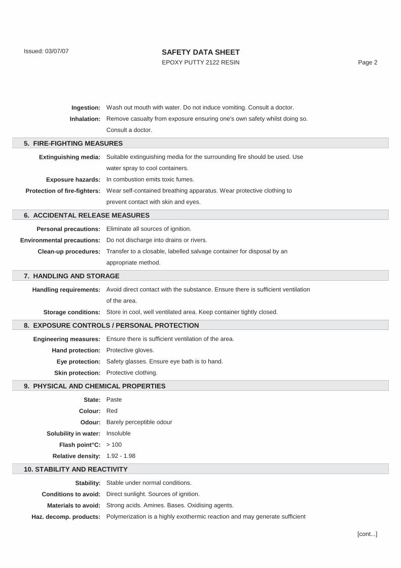
5. FIRE-FIGHTING MEASURES
Extinguishing media: Suitable extinguishing media for the surrounding fire should be used. Use
water spray to cool containers.
Exposure hazards: In combustion emits toxic fumes.
Protection of fire-fighters: Wear self-contained breathing apparatus. Wear protective clothing to
prevent contact with skin and eyes.
6. ACCIDENTAL RELEASE MEASURES
Personal precautions: Eliminate all sources of ignition.
Environmental precautions: Do not discharge into drains or rivers.
Clean-up procedures: Transfer to a closable, labelled salvage container for disposal by an
appropriate method.
7. HANDLING AND STORAGE
Handling requirements: Avoid direct contact with the substance. Ensure there is sufficient ventilation
of the area.
Storage conditions: Store in cool, well ventilated area. Keep container tightly closed.
8. EXPOSURE CONTROLS / PERSONAL PROTECTION
Engineering measures: Ensure there is sufficient ventilation of the area.
Hand protection: Protective gloves.
Eye protection: Safety glasses. Ensure eye bath is to hand.
Skin protection: Protective clothing.
9. PHYSICAL AND CHEMICAL PROPERTIES
State: Paste
Colour: Red
Odour: Barely perceptible odour
Solubility in water: Insoluble
Flash point°C: > 100
Relative density: 1.92 - 1.98
10. STABILITY AND REACTIVITY
Stability: Stable under normal conditions.
Conditions to avoid: Direct sunlight. Sources of ignition.
Materials to avoid: Strong acids. Amines. Bases. Oxidising agents.
Haz. decomp. products: Polymerization is a highly exothermic reaction and may generate sufficient
[cont...]

SAFETY DATA SHEETEPOXY PUTTY 2122 RESIN Page 3
Issued: 03/07/07
heat to cause thermal decomposition and/or rupture containers. In
combustion emits toxic fumes of carbon dioxide / carbon monoxide.
11. TOXICOLOGICAL INFORMATION
Hazardous ingredients: BISPHENOL A-(EPICHLORHYDRIN) {REACTION PRODUCT}
ORL MUS LD50 15600 mg/kg
ORL RAT LD50 11400 mg/kg
SKN RBT LD50 >20 ml/kg
Chronic toxicity: May cause sensitisation by skin contact.
Routes of exposure: Refer to section 4 of SDS for routes of exposure and corresponding
symptoms.
12. ECOLOGICAL INFORMATION
Other adverse effects: Harmful to aquatic organisms.
13. DISPOSAL CONSIDERATIONS
Disposal operations: D10 Incineration on land.
Waste code number: 08 04 09
Disposal of packaging: Dispose of in a regulated landfill site or other method for hazardous or toxic
wastes. Wast Code number 15 01 10
NB: The user's attention is drawn to the possible existence of regional or national
regulations regarding disposal.
14. TRANSPORT INFORMATION
ADR / RID
UN no: 3077 ADR Class: 9
Packing group: III Classification code: M7
Shipping name: ENVIRONMENTALLY HAZARDOUS SUBSTANCE, SOLID, N.O.S.
(BISPHENOL A-(EPICHLORHYDRIN) {REACTION PRODUCT};
REACTION PRODUCT OF EPICHLOROHYDRIN AND BISPHENOL A)
Labelling: 9 Hazard ID no: 90
IMDG / IMO
UN no: 3077 Class: 9
Packing group: III EmS: F-A,S-F
Marine pollutant: .
[cont...]
SAFETY DATA SHEETEPOXY PUTTY 2122 RESIN Page 4
Issued: 03/07/07
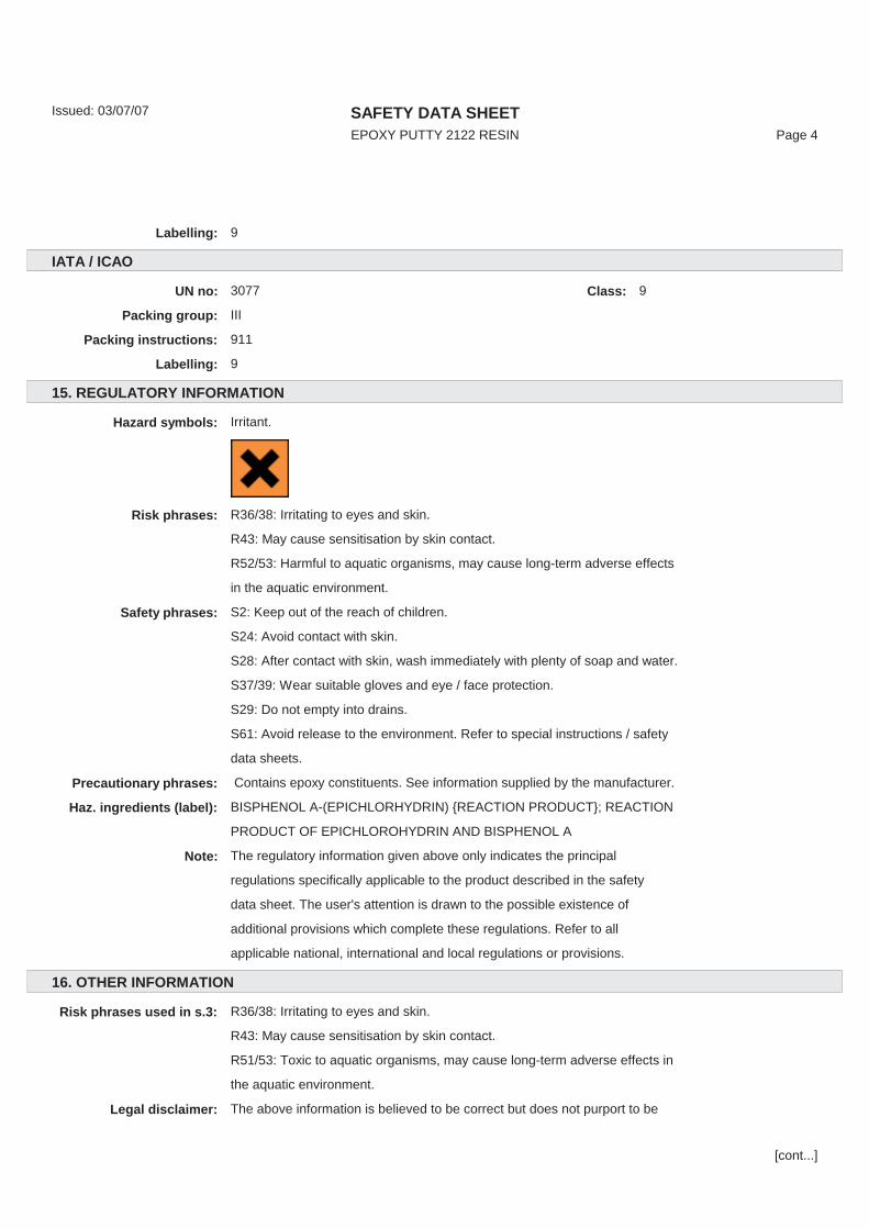
Labelling: 9
IATA / ICAO
UN no: 3077 Class: 9
Packing group: III
Packing instructions: 911
Labelling: 9
15. REGULATORY INFORMATION
Hazard symbols: Irritant.
Risk phrases: R36/38: Irritating to eyes and skin.
R43: May cause sensitisation by skin contact.
R52/53: Harmful to aquatic organisms, may cause long-term adverse effects
in the aquatic environment.
Safety phrases: S2: Keep out of the reach of children.
S24: Avoid contact with skin.
S28: After contact with skin, wash immediately with plenty of soap and water.
S37/39: Wear suitable gloves and eye / face protection.
S29: Do not empty into drains.
S61: Avoid release to the environment. Refer to special instructions / safety
data sheets.
Precautionary phrases: Contains epoxy constituents. See information supplied by the manufacturer.
Haz. ingredients (label): BISPHENOL A-(EPICHLORHYDRIN) {REACTION PRODUCT}; REACTION
PRODUCT OF EPICHLOROHYDRIN AND BISPHENOL A
Note: The regulatory information given above only indicates the principal
regulations specifically applicable to the product described in the safety
data sheet. The user's attention is drawn to the possible existence of
additional provisions which complete these regulations. Refer to all
applicable national, international and local regulations or provisions.
16. OTHER INFORMATION
Risk phrases used in s.3: R36/38: Irritating to eyes and skin.
R43: May cause sensitisation by skin contact.
R51/53: Toxic to aquatic organisms, may cause long-term adverse effects in
the aquatic environment.
Legal disclaimer: The above information is believed to be correct but does not purport to be
[cont...]

SAFETY DATA SHEETEPOXY PUTTY 2122 RESIN Page 5
Issued: 03/07/07
all inclusive and shall be used only as a guide. This company shall not be
held liable for any damage resulting from handling or from contact with the
above product.
[final page]

Certifications
IECEx Certificateof Conformity
INTERNATIONAL ELECTROTECHNICAL COMMISSIONIEC Certification Scheme for Explosive Atmospheres
for rules and details of the IECEx Scheme visit www.iecex.com
Certificate No.: IECEx SIR 09.0082X issue No.:0
Status: Draft Date of Issue: 2009-07-08 Page 1 of 3
Applicant:
Electrical Apparatus: EXHA* compound conduit stopping boxesOptional accessory:
Type of Protection: Flameproof, Increased Safety and Dust
Marking: Ex d e IEx d e IIC GbEx tb IIIC IP66 DbTa = -60°C to +130°C
Approved for issue on behalf of the IECEx Certification Body:
D R Stubbings BA MIET
Position: Certification Manager
Signature: (for printed version)
Date:
1. This certificate and schedule may only be reproduced in full. 2. This certificate is not transferable and remains the property of the issuing body. 3. The Status and authenticity of this certificate may be verified by visiting the Official IECEx Website.
Certificate issued by:SIRA Certification Service
Rake LaneEcclestonChesterCH4 9JN
United Kingdom
Certificate history:
Cable Management Products Limited Station Road Coleshill Birmingham B46 1HT United Kingdom
+130 C
ECE D R
nd Du

IECEx Certificateof Conformity
Certificate No.: IECEx SIR 09.0082X Date of Issue: 2009-07-08 Issue No.: 0
Page 2 of 3
Manufacturer:
Manufacturing location(s): This certificate is issued as verification that a sample(s), representative of production, was assessed and tested and found to comply with the IEC Standard list below and that the manufacturer's quality system, relating to the Ex products covered by this certificate, was assessed and found to comply with the IECEx Quality system requirements. This certificate is granted subject to the conditions as set out in IECEx Scheme Rules, IECEx 02 and Operational Documents as amended. STANDARDS: The electrical apparatus and any acceptable variations to it specified in the schedule of this certificate and the identified documents, was found to comply with the following standards: IEC 60079-0 : 2007-10 Edition: 5
Explosive atmospheres - Part 0:Equipment - General requirements
IEC 60079-1 : 2007-04 Edition: 6
Explosive atmospheres - Part 1: Equipment protection by flameproof enclosures "d"
IEC 60079-30-1 : 2007-01 Edition: 1
Explosive atmospheres - Part 30-1: Electrical resistance trace heating - General and testing requirements
IEC 60079-7 : 2006-07 Edition: 4
Explosive atmospheres - Part 7: Equipment protection by increased safety "e"
This Certificate does not indicate compliance with electrical safety and performance requirements other than those
expressly included in the Standards listed above.
TEST & ASSESSMENT REPORTS: A sample(s) of the equipment listed has successfully met the examination and test requirements as recorded in
Test Report: GB/SIR/ExTR10.0128/00 Quality Assessment Report: GB/BAS/QAR06.0024/02
Cable Management Products Limited Station Road Coleshill Birmingham B46 1HT United Kingdom
uirem
sive here
lil ancei
eress
P
Pa t 1: Eq
art 0-1
s:
0:Equ
pme
ci
ent - G

Annexe: IECEx SIR 09.0082X Issue 0 Annexe.pdf
IECEx Certificateof Conformity
Certificate No.: IECEx SIR 09.0082X Date of Issue: 2009-07-08 Issue No.: 0
Page 3 of 3
Schedule
EQUIPMENT:Equipment and systems covered by this certificate are as follows:
EXHA* Range of Conduit Stopping boxes The EXHA* Range of Conduit Stopping boxes are cylindrical metallic assemblies and are intended for use with conduit. They allow the entry of the cable or conductors through conduit into flameproof enclosures without compromising the explosion protection provided by the enclosure, in accordance with relevant codes of practice. The range comprises three arrangements: HA****G1, conduit stopping box for use with flexible, liquid tight conduit. HA****U, conduit stopping box for use with rigid metal conduit and other threaded fittings HA****E, conduit stopping box for use with rigid metal conduit and other threaded fittings with 90° fitting For the description of parts refer to the Annexe
CONDITIONS OF CERTIFICATION: YES as shown below:
1. The stopping box shall not be used in enclosures where the temperature, at the point of entry/mounting, is outside of the range -60°C to +130°C.
2. The interface seals comply with the requirements of the standards listed in this certificate when the cable glands are fitted to a representative enclosure having a smooth flat mounting surface. In practice the interface between the male thread of the glands and their associated enclosure cannot be defined, therefore it is the users’ responsibility to ensure that the appropriate ingress protection level is maintained at these interfaces.
3. Where the stopping box without sealing ring is installed in protection by enclosure (Ex t) equipment for use in explosive dust atmospheres, it shall only be fitted into enclosures offering a minimum of 5 full threads, with a minimum tolerance of medium or fine according to ISO 965-1 and ISO 965-3 in accordance with IEC 60079-31:2008 clause 5.1.1.
YES wn
used ncl30°C.
r
low
eq

Draf
tfttftftafafafafDDrDrrDDD
Sira Certification ServiceRake Lane, Eccleston, Chester, CH4 9JN, England
Tel: +44 (0) 1244 670900Fax: +44 (0) 1244 681330Email: [email protected]: www.siracertification.com
C E R T I F I C A T I O N
Annexe to: IECEx SIR 09.0082X
Applicant: Cable Management Products Limited
Apparatus: EXHA* compound conduit stopping boxes
Date: 01 June 2010 Page 1 of 3
Form 9530 Issue 1
Description of parts
The HA range, when installed in accordance with the manufacturer’s instructions, are capable ofproviding, with an enclosure on which they are fixed, an ingress protection rating of IP 66.
The range is suitable for use with conduit and to pass circular, unarmoured wires or cables. Allversions of the HA range has the following common parts:
Entry body, front end of gland with male thread for securing into an associated enclosure. Thebase of the front thread is fitted with a sealing washer. The front and rear have male threads.Silicone O-ring, which fits at the front of the ferrule to provide an ingress seal to the unthreadedflamepath between the entry body and compound pot.Compound pot, fits into the entry body, the compound pot body is one part of a two part chamberwhere a two-part epoxy putty setting compound is applied to provide an inner seal around theconductors. The external face when fitted into the entry body makes an unthreaded cylindricalflamepath.Silicone O-ring, which fits over the rear of the compound pot to provide an ingress seal to theunthreaded flamepath between the entry body and ferrule.
The differences between the arrangements are as shown below:
The HA****G1 is fitted with the following additional parts on the rear of the assembly:Insert, second part of a two part compound chamber, inserted in rear of compound pot. Forflexible liquid tight conduit the insert has helical form on rear for threading on to conduitOlive, for clamping of conduit to gland bodyNut which compresses above parts into entry body
The HA****U is fitted with the following additional parts on the rear of the assembly:
Insert, second part of a two part compound chamber, inserted in rear of compound potNut which compresses above parts into entry body. The nut has a female thread on the front andrear, the front female thread attaches to the entry body, the rear thread is for the attachment ofrigid metal conduit or other threaded fitting.
The HA****E is fitted with the following additional parts on the rear of the assembly:
Insert, second part of a two part compound chamber, inserted in rear of compound pot90° Nut which compresses above parts into entry body. The nut has a female thread on the frontand rear which is 90° from each other, the front female thread attaches to the entry body, therear thread is for the attachment of rigid metal conduit or other threaded fitting.
coparts into
ad a s tohrea tti
ng a
Dratio
o DDDrDDDtrDDyhe
raftftb ftftoftftdyfttafafafafpafafarts on
hamb
chaform
smber
on re
dd

Draf
tftDr
aaDDDr
Sira Certification ServiceRake Lane, Eccleston, Chester, CH4 9JN, England
Tel: +44 (0) 1244 670900Fax: +44 (0) 1244 681330Email: [email protected]: www.siracertification.com
C E R T I F I C A T I O N
Annexe to: IECEx SIR 09.0082X
Applicant: Cable Management Products Limited
Apparatus: EXHA* compound conduit stopping boxes
Date: 01 June 2010 Page 2 of 3
Form 9530 Issue 1
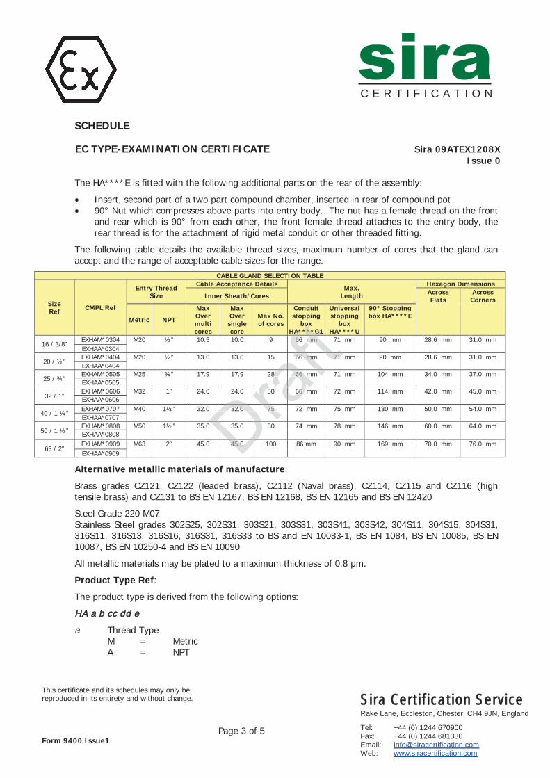
The following table details the available thread sizes, maximum number of cores that the gland canaccept and the range of acceptable cable sizes for the range.
CABLE GLAND SELECTION TABLE
SizeRef CMPL Ref
Entry ThreadSize
Cable Acceptance DetailsMax.
Length
Hexagon Dimensions
Inner Sheath/Cores AcrossFlats
AcrossCorners
Metric NPT
MaxOvermulticores
MaxOver
singlecore
Max No.of cores
Conduitstopping
boxHA****G1
Universalstopping
boxHA****U
90° Stoppingbox HA****E
16 / 3/8”EXHAM*0304 M20 ½” 10.5 10.0 9 66 mm 71 mm 90 mm 28.6 mm 31.0 mmEXHAA*0304
20 / ½”EXHAM*0404 M20 ½” 13.0 13.0 15 66 mm 71 mm 90 mm 28.6 mm 31.0 mmEXHAA*0404
25 / ¾”EXHAM*0505 M25 ¾” 17.9 17.9 28 66 mm 71 mm 104 mm 34.0 mm 37.0 mmEXHAA*0505
32 / 1”EXHAM*0606 M32 1” 24.0 24.0 50 66 mm 72 mm 114 mm 42.0 mm 45.0 mmEXHAA*0606
40 / 1 ¼”EXHAM*0707 M40 1¼” 32.0 32.0 75 72 mm 75 mm 130 mm 50.0 mm 54.0 mmEXHAA*0707
50 / 1 ½”EXHAM*0808 M50 1½” 35.0 35.0 80 74 mm 78 mm 146 mm 60.0 mm 64.0 mmEXHAA*0808
63 / 2”EXHAM*0909 M63 2” 45.0 45.0 100 86 mm 90 mm 169 mm 70.0 mm 76.0 mmEXHAA*0909
Alternative metallic materials of manufacture:
Brass grades CZ121, CZ122 (leaded brass), CZ112 (Naval brass), CZ114, CZ115 and CZ116 (hightensile brass) and CZ131 to BS EN 12167, BS EN 12168, BS EN 12165 and BS EN 12420
Steel Grade 220 M07Stainless Steel grades 302S25, 302S31, 303S21, 303S31, 303S41, 303S42, 304S11, 304S15, 304S31,316S11, 316S13, 316S16, 316S31, 316S33 to BS and EN 10083-1, BS EN 1084, BS EN 10085, BS EN10087, BS EN 10250-4 and BS EN 10090
All metallic materials may be plated to a maximum thickness of 0.8 m.
Product Type Ref:
The product type is derived from the following options:
Thread TypeM = MetricA = NPT
b Material of manufactureB = BrassS = Stainless steel
Rear thread size03 = M16 / 3/8” NPT04 = M20 / ½” NPT05 = M25 / ¾” NPT06 = M32 / 1” NPT07 = M40 / 1 ¼” NPT08 = M50 / 1 ½” NPT09 = M63 / 2” NPT
316S3100
ed to xi
Dra03S
DrDrt DDDDDDraf
t2 ftft1ftft68
30aa S3nd
(NaBS E
bras
m

Draf
t
Sira Certification ServiceRake Lane, Eccleston, Chester, CH4 9JN, England
Tel: +44 (0) 1244 670900Fax: +44 (0) 1244 681330Email: [email protected]: www.siracertification.com
C E R T I F I C A T I O N
Annexe to: IECEx SIR 09.0082X
Applicant: Cable Management Products Limited
Apparatus: EXHA* compound conduit stopping boxes
Date: 01 June 2010 Page 3 of 3
Form 9530 Issue 1
Front thread size04 = M20 / ½” NPT05 = M25 / ¾” NPT06 = M32 / 1” NPT07 = M40 / 1 ¼” NPT08 = M50 / 1 ½” NPT09 = M63 / 2” NPT
Rear section type
G1 = Conduit stopping box for connection to flexible liquid tight conduitU = Universal stopping box for connection to rigid conduit and fittingsE = 90° Universal stopping box for connection to rigid conduit and fittings
Draraft

SSira Certification Service Rake Lane, Eccleston, Chester, CH4 9JN, England Tel: +44 (0) 1244 670900 Fax: +44 (0) 1244 681330 Email: [email protected] Web: www.siracertification.com
C E R T I F I C A T I O N
Project Number 20513 D R Stubbings BA MIETC. Index 04 Certification Manager
This certificate and its schedules may only bereproduced in its entirety and without change.
Page 1 of 5Form 9400 Issue 1
1 EC TYPE-EXAMINATION CERTIFICATE2 Equipment intended for use in Potentially Explosive Atmospheres Directive 94/9/EC
3 Certificate Number: Sira 09ATEX1208X Issue: 0
4 Equipment: EXHA* compound conduit stopping boxes
5 Applicant: Cable Management Products Limited
6 Address: Station RoadColeshillBirminghamB46 1HTUK
7 This equipment and any acceptable variation thereto is specified in the schedule to this certificate andthe documents therein referred to.
8 Sira Certification Service, notified body number 0518 in accordance with Article 9 of Directive 94/9/ECof 23 March 1994, certifies that this equipment has been found to comply with the Essential Health andSafety Requirements relating to the design and construction of equipment intended for use inpotentially explosive atmospheres given in Annex II to the Directive.
The examination and test results are recorded in the confidential reports listed in Section 14.2.
9 Compliance with the Essential Health and Safety Requirements, with the exception of those listed in theschedule to this certificate, has been assured by compliance with the following documents:
EN 60079-0:2009 EN 60079-1:2007 EN 60079-7:2007 IEC 60079-31:2008
10 If the sign ‘X’ is placed after the certificate number, it indicates that the equipment is subject to specialconditions for safe use specified in the schedule to this certificate.
11 This EC type-examination certificate relates only to the design and construction of the specifiedequipment. If applicable, further requirements of this Directive apply to the manufacture and supply ofthis equipment.
12 The marking of the equipment shall include the following:
I M2 or II 2GDEx d e I
Ex d e IIC GbEx tb IIIC IP66 Db
Ta = -60°C to +130°C Ta = -60°C to +130°C
9-1:2007
cert nuthe du
rel
by
e
e
R quiremc mplianc
E
coto the
nfide
n
nstrue Dire
ial
at

SSira Certification Service Rake Lane, Eccleston, Chester, CH4 9JN, England Tel: +44 (0) 1244 670900 Fax: +44 (0) 1244 681330 Email: [email protected] Web: www.siracertification.com
C E R T I F I C A T I O N
SCHEDULE
EC TYPE-EXAMINATION CERTIFICATE Sira 09ATEX1208XIssue 0
This certificate and its schedules may only bereproduced in its entirety and without change.
Page 2 of 5Form 9400 Issue1
13 DESCRIPTION OF EQUIPMENT
EXHA* Range of Conduit Stopping boxes
The EXHA* Range of Conduit Stopping boxes are cylindrical metallic assemblies and are intended foruse with conduit. They allow the entry of the cable or conductors through conduit into flameproofenclosures without compromising the explosion protection provided by the enclosure, in accordancewith relevant codes of practice.
The range comprises three arrangements: HA****G1, conduit stopping box for use with flexible, liquid tight conduit HA****U, conduit stopping box for use with rigid metal conduit and other threaded fittings HA****E, conduit stopping box for use with rigid metal conduit and other threaded fittings with
90° fitting
Description of parts
The HA range, when installed in accordance with the manufacturer’s instructions, are capable ofproviding, with an enclosure on which they are fixed, an ingress protection rating of IP 66.
The range is suitable for use with conduit and to pass circular, unarmoured wires or cables. Allversions of the HA range has the following common parts:
Entry body, front end of gland with male thread for securing into an associated enclosure. Thebase of the front thread is fitted with a sealing washer. The front and rear have male threads.
Silicone O-ring, which fits at the front of the ferrule to provide an ingress seal to the unthreadedflamepath between the entry body and compound pot.
Compound pot, fits into the entry body, the compound pot body is one part of a two part chamberwhere a two-part epoxy putty setting compound is applied to provide an inner seal around theconductors. The external face when fitted into the entry body makes an unthreaded cylindricalflamepath.
Silicone O-ring, which fits over the rear of the compound pot to provide an ingress seal to theunthreaded flamepath between the entry body and ferrule.
The differences between the arrangements are as shown below:
The HA****G1 is fitted with the following additional parts on the rear of the assembly: Insert, second part of a two part compound chamber, inserted in rear of compound pot. For
flexible liquid tight conduit the insert has helical form on rear for threading on to conduit Olive, for clamping of conduit to gland body Nut which compresses above parts into entry body
The HA****U is fitted with the following additional parts on the rear of the assembly:
Insert, second part of a two part compound chamber, inserted in rear of compound pot Nut which compresses above parts into entry body. The nut has a female thread on the front and
rear, the front female thread attaches to the entry body, the rear thread is for the attachment ofrigid metal conduit or other threaded fitting.
withed with a s
t th ofbody co
y bodyti
mm
alealing
e
d to pamon parts:
ead f
h thean ing
ci
e maess p
n
SSira Certification Service Rake Lane, Eccleston, Chester, CH4 9JN, England Tel: +44 (0) 1244 670900 Fax: +44 (0) 1244 681330 Email: [email protected] Web: www.siracertification.com
C E R T I F I C A T I O N
SCHEDULE
EC TYPE-EXAMINATION CERTIFICATE Sira 09ATEX1208XIssue 0
This certificate and its schedules may only bereproduced in its entirety and without change.
Page 3 of 5Form 9400 Issue1
The HA****E is fitted with the following additional parts on the rear of the assembly:
Insert, second part of a two part compound chamber, inserted in rear of compound pot 90° Nut which compresses above parts into entry body. The nut has a female thread on the front
and rear which is 90° from each other, the front female thread attaches to the entry body, therear thread is for the attachment of rigid metal conduit or other threaded fitting.
The following table details the available thread sizes, maximum number of cores that the gland canaccept and the range of acceptable cable sizes for the range.
CABLE GLAND SELECTION TABLE
SizeRef CMPL Ref
Entry ThreadSize
Cable Acceptance DetailsMax.
Length
Hexagon Dimensions
Inner Sheath/Cores AcrossFlats
AcrossCorners
Metric NPT
MaxOvermulticores
MaxOver
singlecore
Max No.of cores
Conduitstopping
boxHA****G1
Universalstopping
boxHA****U
90° Stoppingbox HA****E
16 / 3/8”EXHAM*0304 M20 ½” 10.5 10.0 9 66 mm 71 mm 90 mm 28.6 mm 31.0 mmEXHAA*0304
20 / ½”EXHAM*0404 M20 ½” 13.0 13.0 15 66 mm 71 mm 90 mm 28.6 mm 31.0 mmEXHAA*0404
25 / ¾”EXHAM*0505 M25 ¾” 17.9 17.9 28 66 mm 71 mm 104 mm 34.0 mm 37.0 mmEXHAA*0505
32 / 1”EXHAM*0606 M32 1” 24.0 24.0 50 66 mm 72 mm 114 mm 42.0 mm 45.0 mmEXHAA*0606
40 / 1 ¼”EXHAM*0707 M40 1¼” 32.0 32.0 75 72 mm 75 mm 130 mm 50.0 mm 54.0 mmEXHAA*0707
50 / 1 ½”EXHAM*0808 M50 1½” 35.0 35.0 80 74 mm 78 mm 146 mm 60.0 mm 64.0 mmEXHAA*0808
63 / 2”EXHAM*0909 M63 2” 45.0 45.0 100 86 mm 90 mm 169 mm 70.0 mm 76.0 mmEXHAA*0909
Alternative metallic materials of manufacture:
Brass grades CZ121, CZ122 (leaded brass), CZ112 (Naval brass), CZ114, CZ115 and CZ116 (hightensile brass) and CZ131 to BS EN 12167, BS EN 12168, BS EN 12165 and BS EN 12420
Steel Grade 220 M07Stainless Steel grades 302S25, 302S31, 303S21, 303S31, 303S41, 303S42, 304S11, 304S15, 304S31,316S11, 316S13, 316S16, 316S31, 316S33 to BS and EN 10083-1, BS EN 1084, BS EN 10085, BS EN10087, BS EN 10250-4 and BS EN 10090
All metallic materials may be plated to a maximum thickness of 0.8 μm.
Product Type Ref:
The product type is derived from the following options:
HA a b cc dd e
a Thread TypeM = MetricA = NPT
32.0
35.0
45.0
75
8 66
66
A6
66 mm
o***G1
mm
71

SSira Certification Service Rake Lane, Eccleston, Chester, CH4 9JN, England Tel: +44 (0) 1244 670900 Fax: +44 (0) 1244 681330 Email: [email protected] Web: www.siracertification.com
C E R T I F I C A T I O N
SCHEDULE
EC TYPE-EXAMINATION CERTIFICATE Sira 09ATEX1208XIssue 0
This certificate and its schedules may only bereproduced in its entirety and without change.
Page 4 of 5Form 9400 Issue1
b Material of manufactureB = BrassS = Stainless steel
cc Rear thread size03 = M16 / 3/8” NPT
04 = M20 / ½” NPT 05 = M25 / ¾” NPT 06 = M32 / 1” NPT 07 = M40 / 1 ¼” NPT 08 = M50 / 1 ½” NPT 09 = M63 / 2” NPT
dd Front thread size04 = M20 / ½” NPT
05 = M25 / ¾” NPT 06 = M32 / 1” NPT 07 = M40 / 1 ¼” NPT 08 = M50 / 1 ½” NPT 09 = M63 / 2” NPT
e Rear section type
G1 = Conduit stopping box for connection to flexible liquid tight conduitU = Universal stopping box for connection to rigid conduit and fittingsE = 90° Universal stopping box for connection to rigid conduit and fittings
14 DESCRIPTIVE DOCUMENTS
14.1 Drawings
Refer to Certificate Annexe.
14.2 Associated Sira Reports and Certificate History
Issue Date Report number Comment0 01 June 2010 R20513A/00 The release of the prime certificate.
stopp box stop box
l s
r co
toppin

SSira Certification Service Rake Lane, Eccleston, Chester, CH4 9JN, England Tel: +44 (0) 1244 670900 Fax: +44 (0) 1244 681330 Email: [email protected] Web: www.siracertification.com
C E R T I F I C A T I O N
SCHEDULE
EC TYPE-EXAMINATION CERTIFICATE Sira 09ATEX1208XIssue 0
This certificate and its schedules may only bereproduced in its entirety and without change.
Page 5 of 5Form 9400 Issue1
15 SPECIAL CONDITIONS FOR SAFE USE (denoted by X after the certificate number)
15.1 The stopping box shall not be used in enclosures where the temperature, at the point ofentry/mounting, is outside of the range -60°C to +130°C.
15.2 The interface seals comply with the requirements of the standards listed in this certificate when thecable glands are fitted to a representative enclosure having a smooth flat mounting surface. Inpractice the interface between the male thread of the glands and their associated enclosure cannot bedefined, therefore it is the users’ responsibility to ensure that the appropriate ingress protection level ismaintained at these interfaces.
15.3 Where the stopping box without sealing ring is installed in protection by enclosure (Ex t) equipment foruse in explosive dust atmospheres, it shall only be fitted into enclosures offering a minimum of 5 fullthreads, with a minimum tolerance of medium or fine according to ISO 965-1 and ISO 965-3 inaccordance with IEC 60079-31:2008 clause 5.1.1.
16 ESSENTIAL HEALTH AND SAFETY REQUIREMENTS OF ANNEX II (EHSRs)
The relevant EHSRs that are not addressed by the standards listed in this certificate have beenidentified and individually assessed in the reports listed in Section 14.2.
17 CONDITIONS OF CERTIFICATION
17.1 The use of this certificate is subject to the Regulations Applicable to Holders of Sira Certificates.
17.2 Holders of EC type-examination certificates are required to comply with the production controlrequirements defined in Article 8 of directive 94/9/EC.
o the
n c atesof dif
Regu
are
listed
ons A
NTS
he staSec
OF
dards
9

SSira Certification Service Rake Lane, Eccleston, Chester, CH4 9JN, England Tel: +44 (0) 1244 670900 Fax: +44 (0) 1244 681330 Email: [email protected] Web: www.siracertification.com
C E R T I F I C A T I O N
Certificate Annexe
Certificate Number: Sira 09ATEX1208X
Equipment: EXHA* compound conduit stopping boxes
Applicant: Cable Management Products Limited
This certificate and its schedules may only bereproduced in its entirety and without change.
Page 1 of 2Form 9400 Issue 1
Issue 0
Drawing No. Sheets Rev. Date (Sira stamp) Title7000 1 of 1 1 10 May 10 Stopping box main drawing7001 1 of 1 2 10 May 10 EXHA03 body7001A 1 of 1 2 10 May 10 EXHA04 body7002 1 of 1 3 10 May 10 EXHA04 pot7003 1 of 1 2 10 May 10 EXHA04 insert7004 1 of 1 2 10 May 10 EXHA04 nut7005 1 of 1 2 10 May 10 EXHA04 olive7007 1 of 1 1 10 May 10 ½” NPT body for size M16 conduit7007A 1 of 1 1 10 May 10 ½” NPT body for size M20 conduit7008 1 of 1 1 10 May 10 EXHA03 insert7009 1 of 1 1 10 May 10 EXHA03 nut7010 1 of 1 1 10 May 10 EXHA03 olive7013 1 of 1 2 10 May 10 M25 body7014 1 of 1 2 10 May 10 ¾” NPT body7015 1 of 1 2 10 May 10 EXHA05 compound pot7016 1 of 1 1 10 May 10 EXHA05 insert7017 1 of 1 2 10 May 10 EXHA05 nut7018 1 of 1 1 10 May 10 EXHA05 olive7020 1 of 1 1 10 May 10 M32 body7021 1 of 1 1 10 May 10 1” NPT body7022 1 of 1 1 10 May 10 EXHA06 compound pot7023 1 of 1 1 10 May 10 EXHA06 insert7024 1 of 1 2 10 May 10 EXHA06 nut7025 1 of 1 2 10 May 10 EXHA06 olive7027 1 of 1 1 10 May 10 M40 body7028 1 of 1 1 10 May 10 1 ¼”NPT body7029 1 of 1 1 10 May 10 EXHA07 compound pot7030 1 of 1 1 10 May 10 EXHA07 insert7031 1 of 1 2 10 May 10 EXHA07 nut7032 1 of 1 2 10 May 10 EXHA07 olive7034 1 of 1 1 10 May 10 M50 body7035 1 of 1 1 10 May 10 1 ½” NPT body7036 1 of 1 2 10 May 10 EXHA08 compound pot7037 1 of 1 1 10 May 10 EXHA08 insert7038 1 of 1 2 10 May 10 EXHA08 nut7039 1 of 1 2 10 May 10 EXHA08 olive7041 1 of 1 1 10 May 10 M63 body7042 1 of 1 1 10 May 10 2” NPT body7043 1 of 1 2 10 May 10 EXHA09 compound pot7044 1 of 1 1 10 May 10 EXHA09 insert7045 1 of 1 2 10 May 10 EXHA09 nut7046 1 of 1 1 10 May 10 EXHA09 olive7058 1 of 1 1 10 May 10 EXHA03 nut for HA**0304U7060 1 of 1 1 10 May 10 EXHA04 nut for HA**0404U7061 1 of 1 1 10 May 10 EXHA05 nut for HA**0505U7062 1 of 1 1 10 May 10 EXHA06 nut for HA**0606U
0y 10
0
EXEEXH
H
bodNPT bodT
XHA06 comA06 in
5 u5 oliv
nsertut

SSira Certification Service Rake Lane, Eccleston, Chester, CH4 9JN, England Tel: +44 (0) 1244 670900 Fax: +44 (0) 1244 681330 Email: [email protected] Web: www.siracertification.com
C E R T I F I C A T I O N
Certificate Annexe
Certificate Number: Sira 09ATEX1208X
Equipment: EXHA* compound conduit stopping boxes
Applicant: Cable Management Products Limited
This certificate and its schedules may only bereproduced in its entirety and without change.
Page 2 of 2Form 9400 Issue 1
Drawing No. Sheets Rev. Date (Sira stamp) Title7063 1 of 1 1 10 May 10 EXHA07 nut for HA**0707U7064 1 of 1 1 10 May 10 EXHA08 nut for HA**0808U7065 1 of 1 1 10 May 10 EXHA09 nut for HA**0909U7072 1 of 1 1 10 May 10 EXHA04 insert for HA**0*04U7073 1 of 1 1 10 May 10 EXHA05 insert for HA**0505U7074 1 of 1 1 10 May 10 EXHA06 insert for HA**0606U7075 1 of 1 1 10 May 10 EXHA07 insert for HA**0707U7076 1 of 1 1 10 May 10 EXHA08 insert for HA**0808U7077 1 of 1 1 10 May 10 EXHA09 insert for HA**0909U7059 1 of 1 1 10 May 10 3/8” nut for N/A**0304U7105 1 of 1 1 10 May 10 ½" nut for N/A**0404U7106 1 of 1 1 10 May 10 ¾" nut for N/A**0505U7107 1 of 1 1 10 May 10 1” nut for N/A**0606U7108 1 of 1 1 10 May 10 1 ¼”nut for N/A**0707U7109 1 of 1 1 10 May 10 1 ½” nut for N/A**0808U7110 1 of 1 1 10 May 10 2” nut for N/A**0909U7118 1 of 1 1 10 May 10 90° body for G1fof

InstructionSheets

54
3
61
2
Assembly Instructions for HA Group 1 Flameproof Gland
1. Backnut
2. Olive
3. Insert
4. Pot
5. Body
6. Conduit
Certification DetailsApproved in Exd I&IIC Exe I&II Extb IIICCSA Class I Div 2 ADCD;Class II Div 1 EFG
Sira09ATEX1231X IECEx SIRA09.0103XOperating temperature range:-60ºC to +130ºC
A. Conduit PreparationCut conduit square using a hacksawwith a minimum of 30 teeth per inch.Pull sufficient length ‘L’ of conductors tosuit equipment and twist to form a helix,this gives maximum flexibility.
B. Pass nut (1) and olive (2) over theconduit and conductors. Pass insert (3)
over the conductors and screw into theconduit (6). Remove the pot (4) from thebody (5), pass the body (5) over theconductors, assemble the gland andfully tighten backnut (1) onto body (5)over the conductors, assemble thegland and fully tighten backnut (1) ontobody (5) until the olive (2) is locked ontothe conduit (6), then remove body (5).
C. Spread the conductors out for thecompound packing. Pack thecompound between the conductors asshown. See Notes overleaf and Fig. 7for compound preparation.
IMPORTANT: ENSURE PUTTY FULLYFILLS INSERT GROOVE.
L
Conduit
3
2
1
InsertGroove
CablePreparation
Cable GlandPreparation
Compound
RPM-311
Tel: +44(0)1675 468 213 Email: [email protected] International, Station Road, Coleshill, Birmingham B46 1HT

EPOXY COMPOUND PREPERATIONWhen handling this material, the gloves supplied must be worn. Theepoxy compound is supplied in the form of a two part package.These should be mixed into the ratio of 1:1 until both colours haveblended into one, without any streaks. Rolling and folding is themost satisfactory method of obtaining an even blend. Once mixed,the compound must be used within 30 minutes. After this time it willbegin to stiffen. The compound should be kept at an ambienttemperature of no less than 20°C prior to using. At lowertemperatures it becomes difficult to mix. Should any compoundcome into contact with the skin it should be cleaned off with skincleaner and not allowed to dry on the skin. Only compound forimmediate terminations should be mixed.
D. With all gaps and voids filled, bringthe conductors back together andpack more compound around theoutside of the conductors. Tape theconductors together to preventdisturbance of the compound seal.Pass the pot (4) over the insert (3) andpush until it fully locates over theinsert shoulder. Push excesscompound into the insert and addadditional if required. Remove all
surplus compound from the top of thepot (4) and the joint face as indicated.
NOTE: IT IS IMPORTANT THAT ALLSURPLUS COMPOUND IS REMOVED
E. Pass the conductors through thebody (5), which may have beenpreviously fitted into the equipment.Ensure that compound does not coverend of pot (4)
F. Locate and hand tighten backnut (1)to the body.
G. Allow the compound to cure. (See fig.7 for curing times).
IMPORTANT: THE CONDUCTORSMUST NOT BE MOVED FOR AMINIMUM OF FOUR HOURS.
Assembly Instructions for HA Group 1 Flameproof Gland
35mm
Tape
Compound
4
3
5
1
4
Compound to belevel with top faceof insert
Remove surpluscompound
SPECIAL CONDITIONS FOR SAFE USE :
ACCESSORIES :
Epoxy Compound Cure Time Vs. Temperature
0102030405060708090100
4 8 12 16
Time (Hours)
Shor
e H
ardn
ess
40°C25°C
4°C
Fig. 7
Locate and handtighten backnut to
the body
RPM-311
Tel: +44(0)1675 468 213 Email: [email protected] International, Station Road, Coleshill, Birmingham B46 1HT

FLEXIBLE CONDUIT GLAND SELECTION TABLE ���������
�� �������������������� ���� ��� �� ���� ����� ������������� ���� ��!�
"#���$��������� ��!�"#������%���$����
������!�"��$�����
Across Flats
Across Corners
Across Flats
Across Corners
&'���(�)*�+,�-.(./�&�
0)!'� (&!.� (0!.� (/!.��0.�
&.!1� &.!.� 2� 1.!.�+,,-.(./�&� &�03�
0.���&�0*�+,�-././�&�
0)!'� (&!.� (0!.� (/!.��0.�
&(!.� &(!.� &1� 1.!.�+,,-././�&� &�03�
01���(�/*�+,�-.1.1�&�
(/!.� (4!.� (/!.�(/!2���� (4!.�
�01�&4!2� &4!2� 0)� 1.!.�+,,-.1.1�&� (�/3�
(0���&*�+,�-.'.'�&�
/0!.� /1!.� /0!.�/0!/���� /1!.�
�(0�0/!.� 0/!.� 1.� 1.!.�+,,-.'.'�&� &3�
/.���&5&�/*�+,�-.4.4�&�
1.!.� 1/!.� 10!.� 14!.��/.�
(0!.� (0!.� 41� 1'!.�+,,-.4.4�&� &5&�/3�
1.���&5&�0*�+,�-.).)�&�
'.!.� '/!.� '.!.� '/!.��1.�
(1!.� (1!.� ).� 1)!.�+,,-.).)�&� &5&�03�
'(���0*�+,�-.2.2�&�
4.!.� 4'!.� 4.!.�'2!)���� 4'!.�
�'(�/1!.� /1!.� &..� 4.!.�
+,,-.2.2�&� 03�
"#������6��%�7��
Assembly Instructions for HA Group 1 Flameproof Gland• The compound may be adversely affected by some solvent vapours. If such vapours are likely to be present in
the vicinity of the cable gland in service, suitable precautions may be necessary. • The compound cures at a Shore D hardness of 85, when it can be handled. When used in the HA cable gland,
shown here, the compound when fully cured is suitable for use at a temperature range of –60°C to +130°C.
SPECIAL CONDITIONS FOR USE:1. The Cable Gland has an operating temperature of –60°C to +130°C 2. A seal must be formed between the equipment and the cable gland to maintain the appropriate degree of
protection against ingress of dust, solid objects and water.
ACCESSORIES:Before carrying out the cable gland assembly or stripping of the cable gland assembly, consideration should be givento any cable gland accessories that may be required, such as:-
• Locknut, to secure cable glands into position. • Sealing washer, to offer additional ingress protection of the enclosure at the cable gland entry. • Earthtag, to provide an external armour / braid bonding point. • Serrated washer, to dampen any vibrations that may loosen the locknut or cable gland assembly.
RPM-311
Tel: +44(0)1675 468 213 Email: [email protected] International, Station Road, Coleshill, Birmingham B46 1HT