layer 2 monitoring and host location - liveaction · layer 2 monitoring and host location ......
TRANSCRIPT

www.liveaction.com
Layer 2 Monitoring and Host LocationLayer 2 Monitoring and Host LocationLayer 2 Monitoring and Host LocationLayer 2 Monitoring and Host Location Using LiveAction to monitor and identify inter/intra-switch VLAN configurations, and
locating workstations within the network infrastructure.
May 2014

www.liveaction.com
ContentsContentsContentsContents
Introduction ............................................................................................................................................................. 1
Configuring LiveAction for LAN Support .................................................................................................... 2
LAN Topology View ............................................................................................................................................ 4
LAN Device View .................................................................................................................................................. 5
Host Location and Identification ................................................................................................................... 7
Use Case Scenario: Locating a Device Using Flow and LAN Capabilities ................................... 8
Use Case Scenario: Identifying Misconfigured Trunk Ports .............................................................. 11

www.liveaction.com 1
IntroductionIntroductionIntroductionIntroduction
LiveAction provides the capability to monitor and identify VLAN configurations as they span across the layer
2 topology. By identifying the configured VLANs and the devices which carry them, the network
administrator can quickly visualize the traffic flow of packets within the distribution and access layers of the
network infrastructure. As an added bonus, LiveAction also allows the user to pinpoint the location of
workstations and server machines based on their IP address and MAC address. Leveraging the existing flow
visualization provided by LiveAction greatly helps in tracking down devices – especially in environments
which support BYOD policies. This application note provides instructions on configuring and navigating
through the LiveAction LAN features, as well as various use cases involving VLAN configurations and
locating devices within the enterprise.

www.liveaction.com 2
Configuring LiveAction for LAN SupportConfiguring LiveAction for LAN SupportConfiguring LiveAction for LAN SupportConfiguring LiveAction for LAN Support
There are no extra configuration steps necessary in order to support the monitoring of layer 2 ports. The
additional support for layer 2 enables the network administrator to add various trunking interfaces as they
would add layer 3 ports. With regard to VLANs, please keep in mind that the Select Interfaces section will
only display layer 3 switched virtual interfaces (SVI).
The next section in the device configuration wizard introduces the ability to add, up to 25, layer 2 VLANs
into the topology.
Since it is possible to create Layer 2 Etherchannels, LiveAction also allows the addition of these interface
types into the topology. Regardless if it is a hardware port, or an Etherchannel port, the letter “T” denotes

www.liveaction.com 3
the configured interface as a trunk port. In order to reduce clutter in the topology view, access port
configuration and statistics can only be viewed through the LAN Device View.
This is the result of the Select Interfaces and Select VLANs configuration. The square icon represents pure
layer 2 VLANs on the switch. The values located within the square icons represent the aggregate
bandwidth of the hardware ports within the VLAN. As we move up to the distribution switches, we will see
the same VLANs as circles, which represents the configuration of SVIs – generally with IP addresses.
Hovering over the “Other VLANs” icon will show the remaining VLANs that are not being actively
monitored by LiveAction. Finally, dashed lines are added to identify what VLANs are associated with a
particular trunk interface, while a solid line is used to show the association of hardware ports to a port-
channel interface.
Similar to the layer 3 and trunk interfaces, layer 2 interface icons will change colors to represent various
alerts. In this case, we see that there are some packet drops occurring in the outbound direction of one or
more of VLAN10’s access ports. Alerts can be configured by accessing the ToolsToolsToolsTools > Configure AlertsConfigure AlertsConfigure AlertsConfigure Alerts
dialog.

www.liveaction.com 4
LAN Topology ViewLAN Topology ViewLAN Topology ViewLAN Topology View
The main benefit of using LiveAction for monitoring switches is its ability to simplify the visualization of
VLAN configurations between devices. By simply accessing the LAN tab, we are presented with a
topological representation of our switched infrastructure, on a per VLAN basis.
We see that the blue line represents the configured path of VLAN 10. By cycling through the Selected VLAN
dropdown, we can also select other configured VLANs in the topology to see how they traverse across the
network. It is important to note that the actual traffic path may not utilize some of these lines, since the
Spanning Tree Protocol (STP) port states must be taken into consideration; fortunately, LiveAction also
supports visualization of STP. Refer to the STP Application Note for further details.

www.liveaction.com 5
LAN Device ViewLAN Device ViewLAN Device ViewLAN Device View
Double-clicking the device, or selecting it through the device list opens up the LAN Device View, which
provides a detailed table describing port status, configured VLANs, layer 2 QoS data, and the neighboring
devices. By default, the VLAN dropdown box is set to “All”, but the user can change it to be VLAN specific.
Using the dropdown box will limit the interfaces displayed to only those which are part of the selected
VLAN.
This view is comparable to running the “show interface trunk”, “show vlan”, and “show interface” Cisco IOS
commands, but with the added benefit of including neighbor device details. Active access ports will also list
IP addresses learned from the interface, which can be useful in identifying and troubleshooting IP address
issues on endpoint devices.
Right-click on the device table view to Export Data in CSV format. Use this utility to create an instant
snapshot of the trunk and access ports of the switch along with other details including its connected
devices.

www.liveaction.com 6
Layer 2 QoSLayer 2 QoSLayer 2 QoSLayer 2 QoS
Another benefit of LiveAction is its ability to report packet drops based on the layer 2 hardware queues and
thresholds. This is particularly important when working with upstream ports, where congestion may
overwhelm the various hardware queues. The Layer 2 QoS Statistics window displays pertinent information
regarding the assigned trust value of the interface, total dropped packets, and drop rate. With the larger
supported switches, it is also possible to obtain COS-Map and DSCP range values for each interface.
The Layer 2 QoS Statistics is currently available for the 7600 routers, Catalyst 6500, Catalyst 3750/3560,
Catalyst 2960, Metro 3400, and Metro 2400 series devices; which can be accessed by clicking on the
“Show Layer 2 QoS” button in the LAN Device View.
It is possible to identify the total number of packets dropped on a queue and threshold combination, as
well as the current drop rate in packets per second (pps). When viewing the Layer 2 QoS Statistics table,
please note that any queues that are mapped to COS 5 is assumed to be a priority queue.

www.liveaction.com 7
Host Location and IdentificationHost Location and IdentificationHost Location and IdentificationHost Location and Identification
By selecting the “Find IP/MAC” button in the LAN Topology View, it is possible to locate devices within the
network based on the specified IP or MAC address. Generally, using the IP address tends to be more
accurate as it is a globally unique identifier. In cases where there are duplicate entries for IP or MAC
addresses, multiple devices and interfaces will be displayed. Despite this small drawback, the Find IP/MAC
feature works to limit the range of necessary devices to investigate.
Here we see that the IP address 4.4.4.2 is connected to Gi2/31 on the SCOPE_c4503S7-210. With the MAC
address resolution we get two entries mapped, with another one mapped to the Fa1/31 on the Cisco
6509_140. Given an IP address and MAC address it is possible to locate the physical location of a network
device. This is great for disabling network access for rogue devices.
A few snippets of the CLI output will verify our results:
SCOPE_c4503S7-210#show ip arp | in 4.4.4.2
Internet 4.4.4.2 - aabb.cc00.0002 ARPA
SCOPE_c4503S7-210#show mac address-table dyn int gi 2/31
Unicast Entries
vlan mac address type protocols port
-------+---------------+--------+---------------------+--------------------
Gi2/31 aabb.cc00.0002 dynamic ip,ipx,assigned,other GigabitEthernet2/31

www.liveaction.com 8
Use Case Scenario: LocatUse Case Scenario: LocatUse Case Scenario: LocatUse Case Scenario: Locating a Device Using Flow and LAN ing a Device Using Flow and LAN ing a Device Using Flow and LAN ing a Device Using Flow and LAN
CapabilitiesCapabilitiesCapabilitiesCapabilities
The following topology represents a standard Core-Distribution-Access hierarchical design which will be
used in order to identify the true end-to-end path of the traffic, as well as its actual endpoint devices:
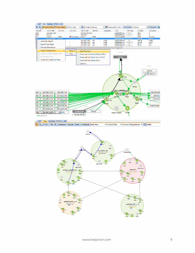
In order to look into the actual flow properties and determine an interesting flow, we select the
Cisco6509_140 device and create a display filter to isolate a single source and destination IP address. This
reduces the clutter and helps with creating a simple line displaying the traversed network path.
www.liveaction.com 9

www.liveaction.com 10
Since the Catalyst 2960 switches do not support NetFlow, we will have to rely on the IP/MAC Locator tool
to identify the rest of the path. A quick search for the source IP address (10.255.0.200) displays the
following information:
For the sake of verification, the CLI will be used to ensure that the correct information is provided to us by
LiveAction.
SCOPE_c4503S7-210#show ip arp 10.255.0.200
Protocol Address Age (min) Hardware Addr Type Interface
Internet 10.255.0.200 16 aaaa.aa00.0011 ARPA Vlan100
SCOPE_c4503S7-210#show mac address-table | in aaaa.aa00.0011
100 aaaa.aa00.0011 dynamic ip,ipx,assigned,other GigabitEthernet2/2
SCOPE_c4503S7-210#show cdp neighbors gi2/2
Capability Codes: R - Router, T - Trans Bridge, B - Source Route Bridge
S - Switch, H - Host, I - IGMP, r - Repeater, P - Phone,
D - Remote, C - CVTA, M - Two-port Mac Relay
Device ID Local Intrfce Holdtme Capability Platform Port ID
cat2960SCOPE_1-14
Gig 2/2 177 S I WS-C2960- Gig 0/2
cat2960SCOPE_1-14#show mac address-table dynamic interface fa0/10
Mac Address Table
-------------------------------------------
Vlan Mac Address Type Ports
---- ----------- -------- -----
100 aabb.ccdd.eeff DYNAMIC Fa0/10
Total Mac Addresses for this criterion: 1
cat2960SCOPE_1-14#
Another method is to use the LAN Device View, which will also display the associated IP address on the
access ports. The network administrator can even export the data into a CSV format for tracking and
auditing known endpoints on a per VLAN, or all VLAN, basis.

www.liveaction.com 11
Use Case Scenario: Identifying Misconfigured Trunk PortsUse Case Scenario: Identifying Misconfigured Trunk PortsUse Case Scenario: Identifying Misconfigured Trunk PortsUse Case Scenario: Identifying Misconfigured Trunk Ports
The following setting displays a VLAN configuration issue identified by LiveAction.
The topology clearly indicates a disconnect between the SCOPE_c4503S7-210’s trunk port (Gi2/2) and the
cat2960SCOPE_1-14’s trunk port (Gi0/2). By looking at the LAN Device View, it is possible to verify the
configured VLANs on each trunk interface. LiveAction’s high visibility allows the administrator to quickly
isolate the problem down to the affected switches, removing the need to manually log in to every switch
in order to verify their configuration.

www.liveaction.com 12
The above diagram shows SCOPE_c4503S7-210’s trunk port configurations, which is allowing VLAN 100 –
102 across the trunk port Gi 2/2.
The same cannot be said about the cat2960SCOPE_1-14, which is only trunking VLAN 101 and 102,
causing the topology disconnect. By adding the appropriate VLAN configuration on the interface, we can
remediate this issue.
cat2960SCOPE_1-14(config)#int gi 0/2
cat2960SCOPE_1-14(config-if)#switchport trunk allow vlan add 100
Copyright © 2014 ActionPacked Networks, Inc. dba LiveAction. All rights reserved. LiveAction, the
LiveAction logo and LiveAction Software are trademarks of ActionPacked Networks, Inc. Other company
and product names are the trademarks of their respective companies.
LiveAction
825 San Antonio Road, Suite 209
Palo Alto, CA 94303 N0003-001A-0414