layered architecture & protocols - · pdf fileprotocols application layer transport layer...
TRANSCRIPT
Layered Architecture & Protocols
Week 7 – Layered Architecture & Protocols
Introduction
The concept of layers is used to describe communication from one computer to another.
Most networks are organized as a series of layers or levels to reduce their design complexity.
Number of layers, the name of each layer, the content of each layer, and the function of each layer differ from network to network
We use the concept of layers in our daily life.
As an example, let us consider two friends who
communicate through postal mail.
The process of sending a letter to a friend would
be complex if there were no services available
from the post office.
Layered tasks
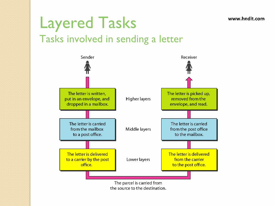
Layered TasksTasks involved in sending a letter
Communication
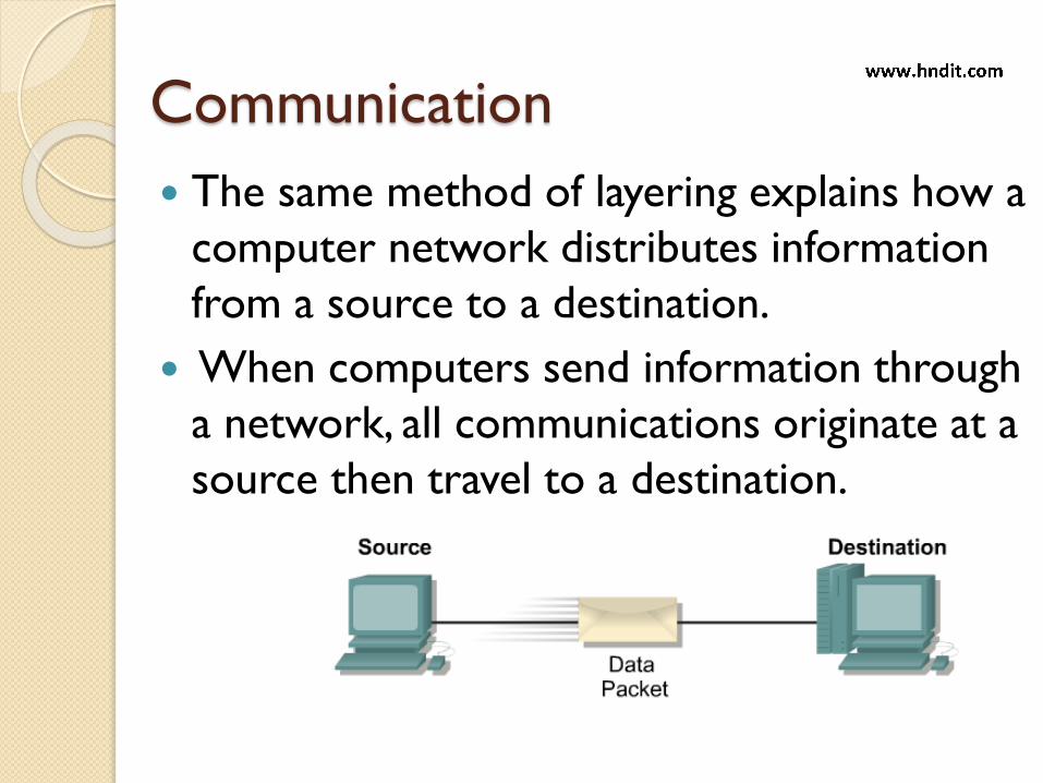
The same method of layering explains how a
computer network distributes information
from a source to a destination.
When computers send information through
a network, all communications originate at a
source then travel to a destination.

Packet or Data
The information that travels on a network is
generally referred to as data or a packet.
A packet is a logically grouped unit of information
that moves between computer systems.
As the data passes between layers, each layer adds
additional information that enables effective
communication with the corresponding layer on
the other computer.

What is a protocol?
Protocol – An agreement about how to do
something
◦ This enables computers and software built by
different people to be able to communicate in the
same language
Examples that we have seen:
◦ Hyper Text Transfer Protocol (HTTP) – Web
Browser
◦ File Transfer Protocol (FTP) – File transfer
◦ Simple Mail Transfer Protocol (SMTP) – Email
◦ Internet Protocol (IP) – Packets across the Internet
discuss more in later…

Contents!
Human Protocols
Sending a letter via the postal service
Shayne Evans
5501 Sennott Sq.
Pittsburgh, PA. 15260
Kim Morrison
123 Somewhere St.
Someplace, PA. 15555
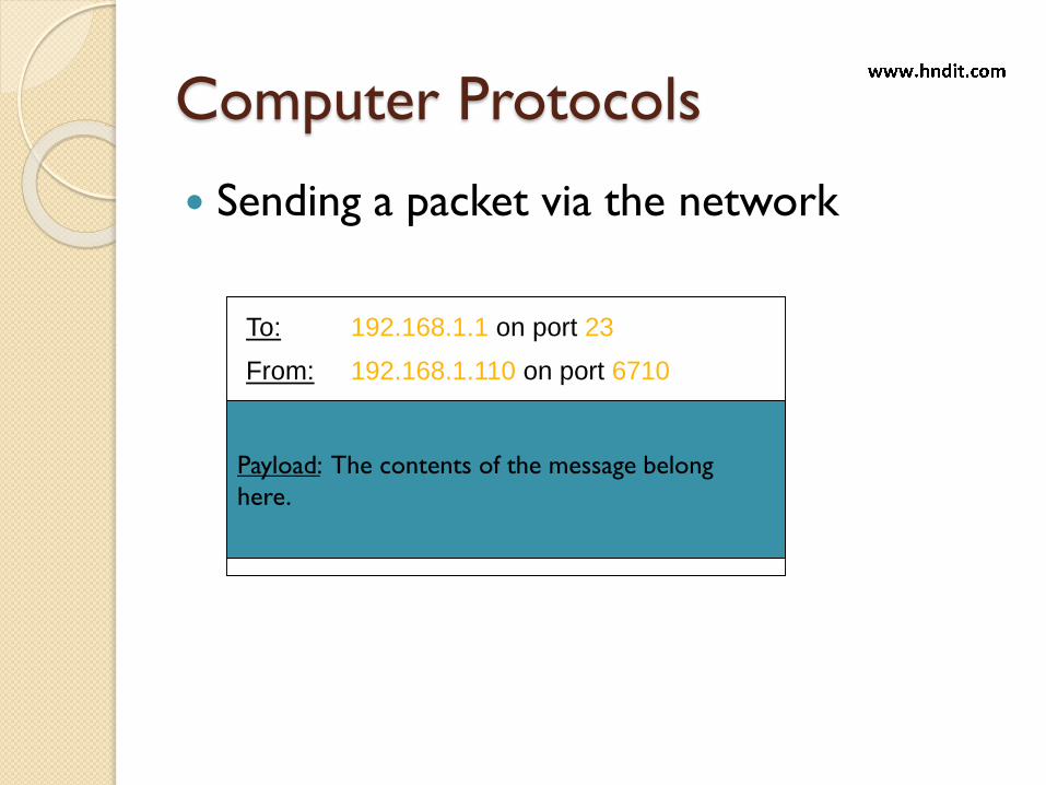
Computer Protocols
Sending a packet via the network
To: 192.168.1.1 on port 23
From: 192.168.1.110 on port 6710
Payload: The contents of the message belong
here.
Contents!!!
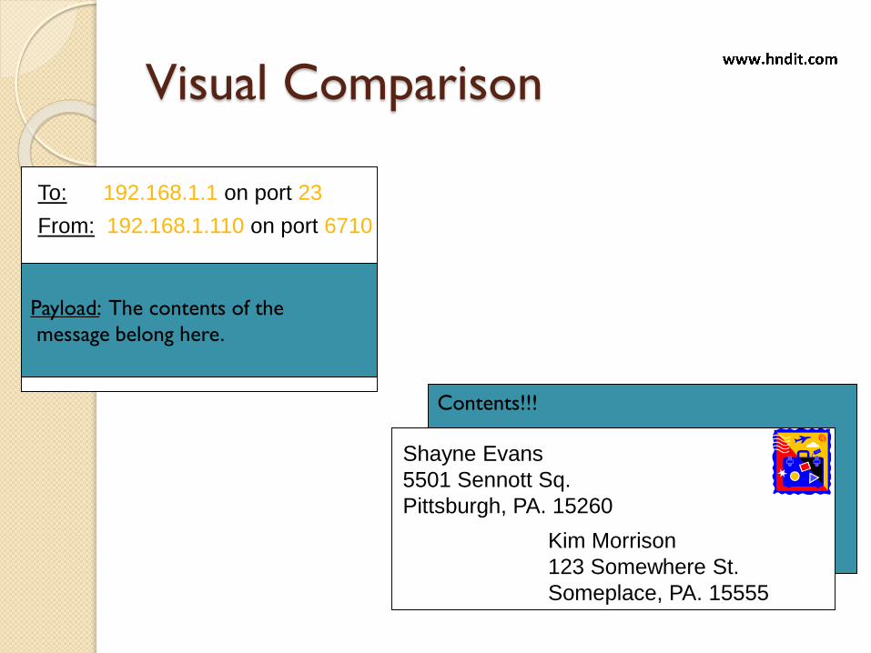
Visual Comparison
To: 192.168.1.1 on port 23
From: 192.168.1.110 on port 6710
Payload: The contents of the
message belong here.
Contents!
Shayne Evans
5501 Sennott Sq.
Pittsburgh, PA. 15260
Kim Morrison
123 Somewhere St.
Someplace, PA. 15555

Textual Comparison
The address of the letter is the
destination of the packet
The return address of the letter is the
source of the packet
The content of the envelope is the
payload of the packet
In both protocols, if you disobey the rules
your message will not be received

Protocol Layers
Protocols can be layered on top of other
protocols to enable new ways of
communicating
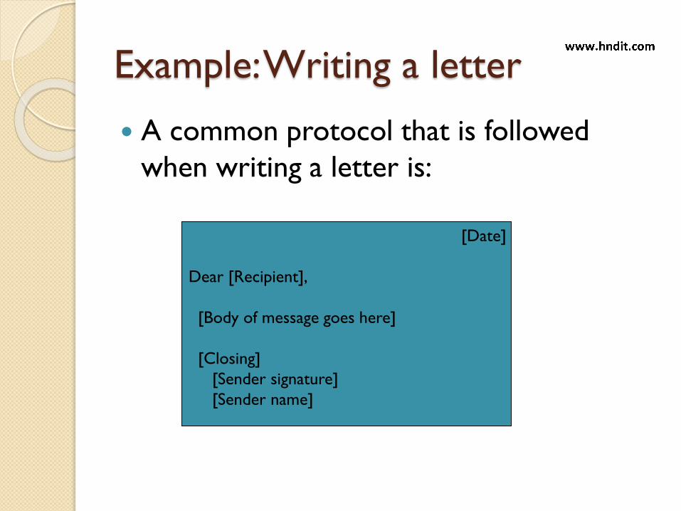
Example: Writing a letter
A common protocol that is followed
when writing a letter is:
[Date]
Dear [Recipient],
[Body of message goes here]
[Closing]
[Sender signature]
[Sender name]

Example: Writing a letter
A common protocol that is followed
when writing a letter is:
04/01/2008
Dear Kim,
Hey there! What’s up? I’m good. Thanks.
Sincerely,
Shayne EvansShayne Evans

04/01/2008
Dear Kim,
Hey there! What’s up? I’m good. Thanks.
Sincerely,
Shayne EvansShayne Evans
Example: Writing a Letter
After following the protocol for writing a
letter, I can use the protocol for sending a
letter via the postal service:
Shayne Evans
5501 Sennott Sq.
Pittsburgh, PA. 15260
Kim Morrison
123 Somewhere St.
Someplace, PA. 15555

Example: Writing a letter
Thus, I have layered two protocols on top
of each other.
The lower protocol provides a service
used by the higher protocols.
Letter Writing Protocol
Sending a Letter via USPS Protocol
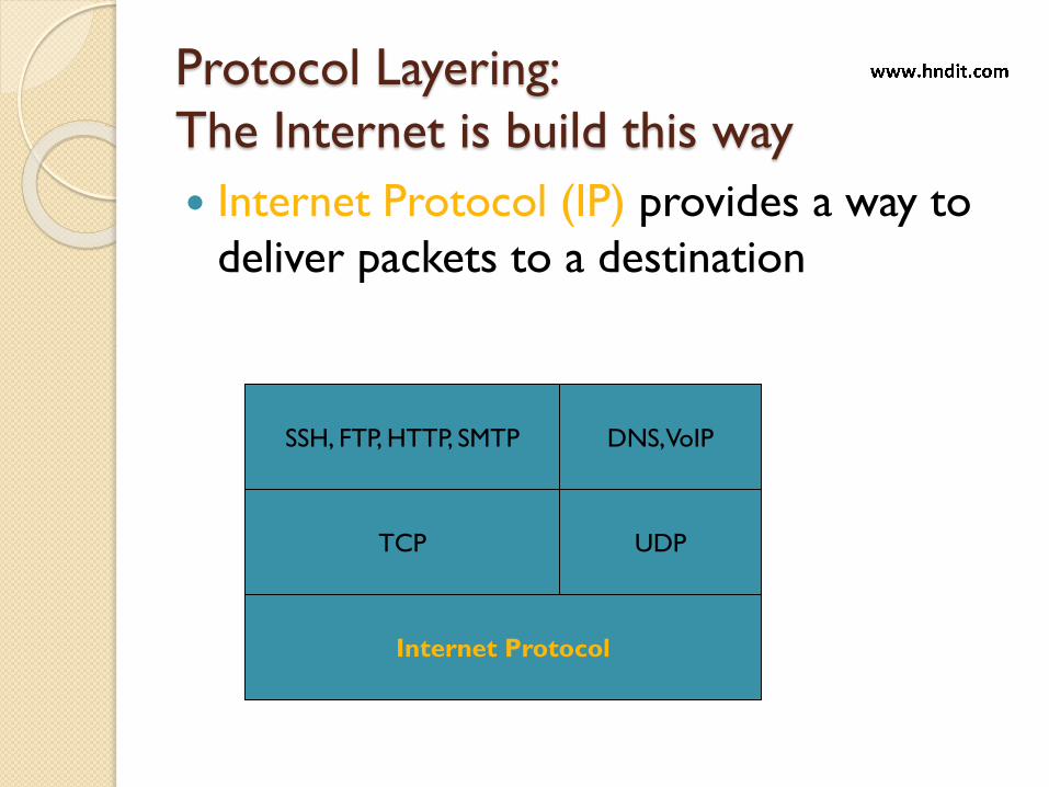
Protocol Layering:
The Internet is build this way
Internet Protocol (IP) provides a way to
deliver packets to a destination
TCP
Internet Protocol
SSH, FTP, HTTP, SMTP
UDP
DNS, VoIP

TCP uses packets to maintain
connections” across a network, and thus
is layered above IP
TCP
Internet Protocol
SSH, FTP, HTTP, SMTP
UDP
DNS, VoIP
Protocol Layering:
The Internet is build this way
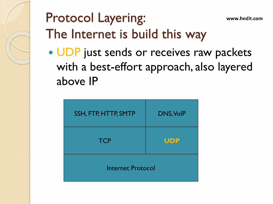
UDP just sends or receives raw packets
with a best-effort approach, also layered
above IP
TCP
Internet Protocol
SSH, FTP, HTTP, SMTP
UDP
DNS, VoIP
Protocol Layering:
The Internet is build this way

SSH, FTP, HTTP, SMTP and many more
applications use TCP connections to
communicate data back and forth
TCP
Internet Protocol
SSH, FTP, HTTP, SMTP
UDP
DNS, VoIP
Protocol Layering:
The Internet is build this way
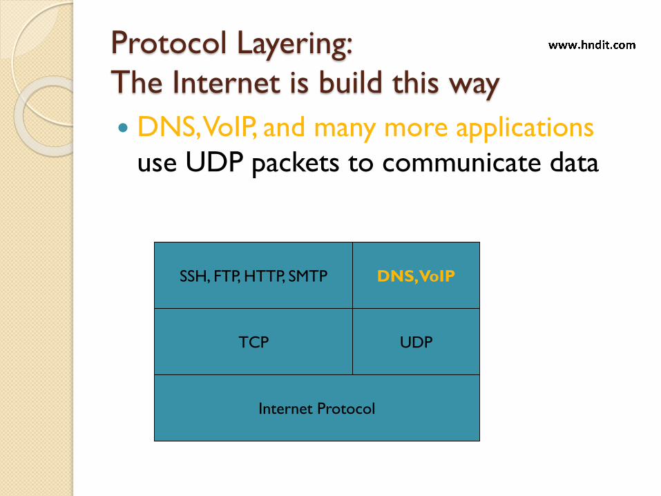
DNS, VoIP, and many more applications
use UDP packets to communicate data
TCP
Internet Protocol
SSH, FTP, HTTP, SMTP
UDP
DNS, VoIP
Protocol Layering:
The Internet is build this way

The Internet is built this way
The Internet Protocol is near the bottom layer
◦ It provides the rules for forming packets and passing them to their destination
Above that are the TCP / UPD protocols
Above that are the HTTP/FTP/SSH/SMTP protocols

Protocol Layers
Thus we have the following protocol
layers:
Postal Service Protocol
Reversing Messages Protocol
Letter Writing Protocol
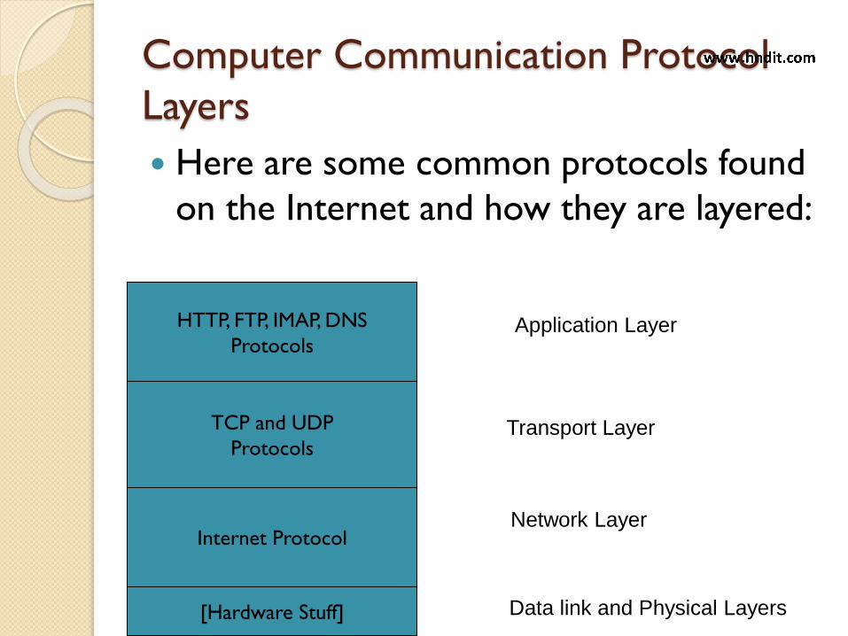
Computer Communication Protocol
Layers
Here are some common protocols found
on the Internet and how they are layered:
Internet Protocol
HTTP, FTP, IMAP, DNS
Protocols
TCP and UDP
Protocols
Application Layer
Transport Layer
Network Layer
[Hardware Stuff] Data link and Physical Layers
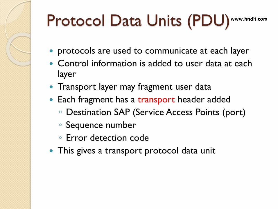
Protocol Data Units (PDU)
protocols are used to communicate at each layer
Control information is added to user data at each layer
Transport layer may fragment user data
Each fragment has a transport header added
◦ Destination SAP (Service Access Points (port)
◦ Sequence number
◦ Error detection code
This gives a transport protocol data unit

PDUs in TCP/IP
26

Example Header Information
Destination port
Sequence number
Checksum

Protocol
A data communications protocol is a set
of rules or an agreement that determines
the format and transmission of data.
◦ That make communication on a network
more efficient.
◦ For example, while flying an airplane, pilots
obey very specific rules for communication
with other airplanes and with air traffic
control.
Protocol
In order for data packets to travel from a
source to a destination on a network, it is
important that all the devices on the
network speak the same language or
protocol
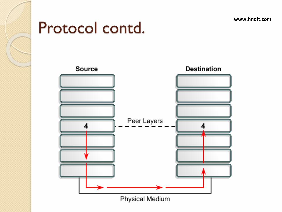
Protocol contd.

Protocol contd.
Layer 4 on the source computer
communicates with Layer 4 on the destination
computer. The rules and conventions used for
this layer are known as Layer 4 protocols.
A protocol in one layer performs a certain set
of operations on data as it prepares the data
to be sent over the network.
The data is then passed to the next layer
where another protocol performs a different
set of operations.

Protocol contd.
Once the packet has been sent to the destination, the protocols undo the construction of the packet that was done on the source side. This is done in reverse order.
The protocols for each layer on the destination return the information to its original form, so the application can properly read the data.
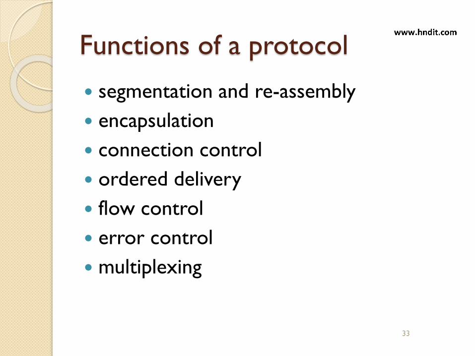
Functions of a protocol
segmentation and re-assembly
encapsulation
connection control
ordered delivery
flow control
error control
multiplexing
33
Protocol Architecture
Layered structure of hardware and
software that supports the exchange of
data between systems as well as a
distributed application (e.g. email or file
transfer
Each protocol provides a set of rules

Need For Protocol Architecture
E.g. File transfer
◦ Source must activate communications Path or inform network of destination
◦ Source must check if destination is prepared to receive
◦ File transfer application on source must check if destination file management system will accept and store sender’s file
◦ May need file format translation
Task broken into subtasks
Implemented separately in layers in stack
Functions needed in both systems
Enable peer layers to communicate

Key Elements of a Protocol
Syntax
◦ Creates a data block format understood by all
Semantics
◦ Control information for coordinating and
error handling
Timing(synchronization)
◦ Synchronizes timing for functions such as
speed matching and sequencing
Goals of Layered Protocols
To provide a logical decomposition of a
complex network into smaller, more
understandable parts(layers)
To provide standard interfaces between
network functions
◦ e.g. standard interfaces between s/w interface
modules
To provide a means to predict and control any
changes made to the network logic

To provide symmetry in functions performed at
each node in the network. Each layer performs the
same function as its counterpart in other nodes of
the network.
To provide standard language to clarify
communication between and among network
designers, managers, vendors and users when
discussing network functions
Goals of Layered Protocols

Communication between layers
A layer is a service provider - may consist of
several service functions
◦ e.g. Code conversions
International Alphabet #5(IA5) to/from EBCDIC
Calendar dates to/from numeric form
A function is a subset of a layer e.g. actual software sub-routines in a program
A layer add value to the services provided by
the layers below it
39

Why Standard ?
• Standard allows products from multiple vendors
to communicate
Users (purchasers) have flexibility in selecting equipment
or software
Standards are essential in creating and
maintaining an open and competitive market for
equipment manufacturers and in guaranteeing
national and international interoperability of
data and telecommunications technology and
processes.
Standards provides guidelines to manufacturers,
vendors, government agencies, and other service
providers to ensure the king of interconnectivity
necessary in today’s marketplace and in
international communications.
Standards

OSI & TCP/IP Architecture
The OSI and TCP/IP models have layers that
explain how data is communicated from one
computer to another.
The models differ in the number and
function of the layers.
Each model can be used to help ,describe and
provide details about the flow of information
from a source to a destination

OSI TCP/IP
OSI model– Open system
InterconnectionProtocol Architecture

Why need OSI model
• To address the problem of networks increasing in size and in number, the ISO (International Organization for Standardization) researched many network schemes.
• Recognized that there was a need to create a network model that would help network builders implement networks that could communicate and work together and released the OSI reference model in 1984.
45
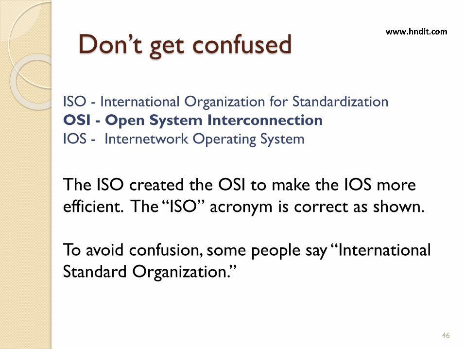
Don’t get confused
46
ISO - International Organization for Standardization
OSI - Open System Interconnection
IOS - Internetwork Operating System
The ISO created the OSI to make the IOS more
efficient. The “ISO” acronym is correct as shown.
To avoid confusion, some people say “International
Standard Organization.”

The OSI Model
Established in 1947, the International Standards
Organization (ISO) is a multinational body
dedicated to worldwide agreement on
international standards.
An ISO standard that covers all aspects of
network communications is the Open Systems
Interconnection (OSI) model. It was first
introduced in the late 1970s.
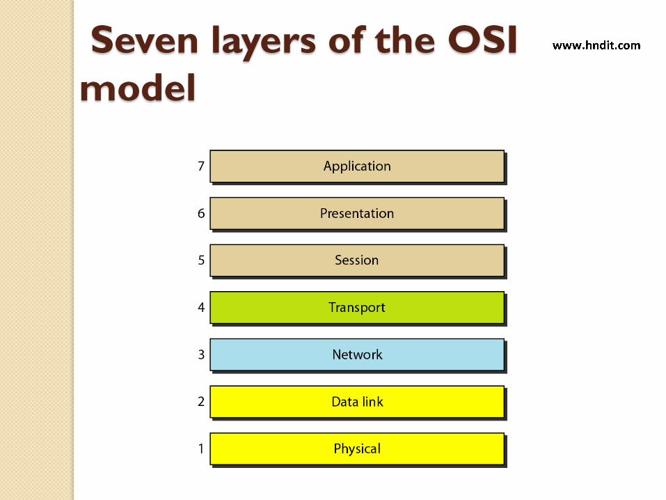
Seven layers of the OSI
model
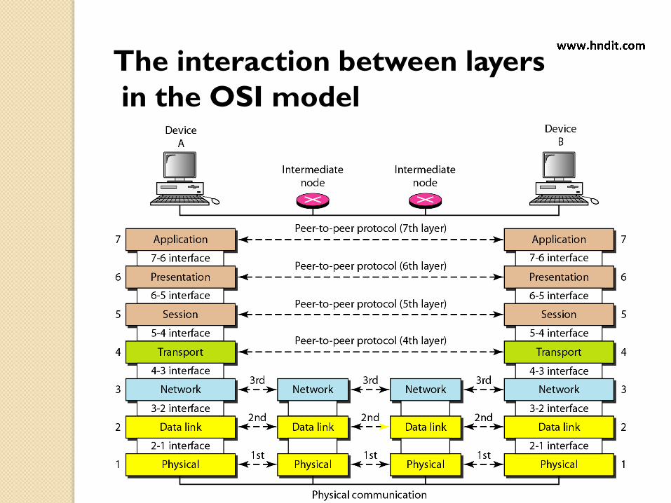
The interaction between layers
in the OSI model

1. Physical Layer
2. Data Link Layer
3. Network Layer
4. Transport Layer
5. Session Layer
6. Presentation Layer
7. Application Layer
1. Physical Layer
2. Data Link Layer
3. Network Layer
4. Transport Layer
5. Session Layer
6. Presentation Layer
7. Application Layer
User A User B
110110011110000 Medium
OSI model
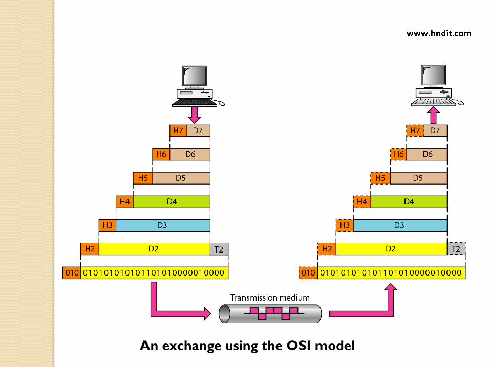
An exchange using the OSI model

Layer 1 - Physical layer
Coordinates the functions required to transmit a stream of
bits over a physical medium.
Deals with electrical and mechanical specifications of the
interface and transmission medium.
Physical Layer specifications define features such as:
o voltage
o timing sequence of voltage changes
o data rate 19.2 kbps
o distance of transmission – 50 ft
o physical connectors. ( DB 9 / DB 25)

Layer 1 - Physical layer
Defines the type of transmission medium
Defines the type of encoding.
Network Devices - Repeaters.
The physical layer is responsible for movements of
individual bits from one hop (node) to the next.
Note

Layer 1 - Physical layer

Bus MAC Addresses Star Ring
Defines physical addressing and network topology
DLL transforms the physical layer function of transmission of
raw bits into a reliable one and is responsible for node to node
delivery.
Concerns with error notification, detection & correction
sequencing of frames and flow control.
Transmits Frames.
Network Devices – Bridges and Switches
Layer 2 – Data link layer
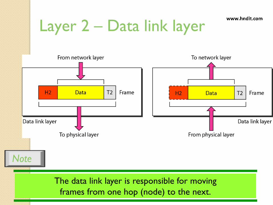
Layer 2 – Data link layer
Note
The data link layer is responsible for moving
frames from one hop (node) to the next.

Hop-to-hop delivery
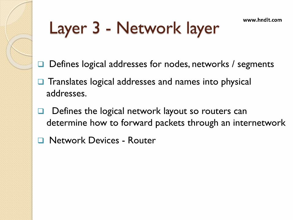
Layer 3 - Network layer
Defines logical addresses for nodes, networks / segments
Translates logical addresses and names into physical
addresses.
Defines the logical network layout so routers can
determine how to forward packets through an internetwork
Network Devices - Router
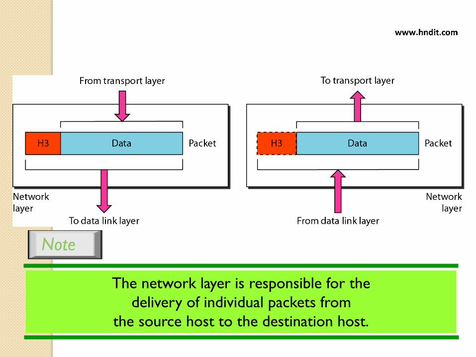
The network layer is responsible for the
delivery of individual packets from
the source host to the destination host.
Note

Source-to-destination delivery
Layer 4 - Transport layer
61
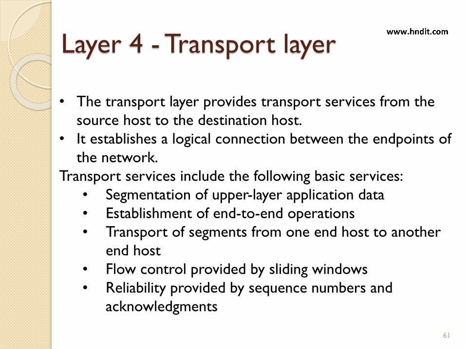
• The transport layer provides transport services from the
source host to the destination host.
• It establishes a logical connection between the endpoints of
the network.
Transport services include the following basic services:
• Segmentation of upper-layer application data
• Establishment of end-to-end operations
• Transport of segments from one end host to another
end host
• Flow control provided by sliding windows
• Reliability provided by sequence numbers and
acknowledgments

Responsible for delivering data, error free and in correct
sequence without any losses and duplications
Protocols
oTCP – connection oriented: reliable and provides
guaranteed delivery
o UDP – connectionless, unreliable, less overhead,
reliability is provides by the Application layer user datagram
Protocol
Establishes, maintains and terminates virtual circuits
Provides error detection and recovery.
Layer 4 - Transport layer
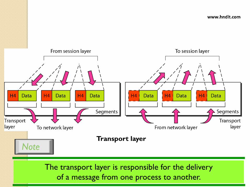
Transport layer
The transport layer is responsible for the delivery
of a message from one process to another.
Note
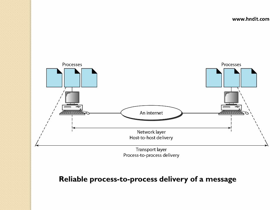
Reliable process-to-process delivery of a message
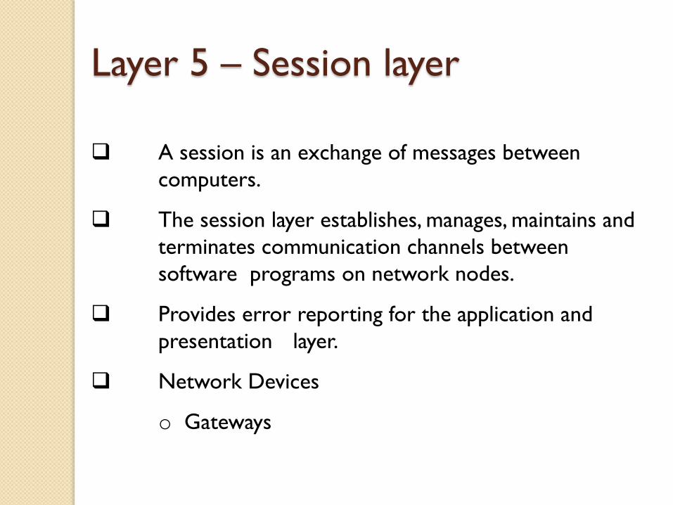
A session is an exchange of messages between
computers.
The session layer establishes, manages, maintains and
terminates communication channels between
software programs on network nodes.
Provides error reporting for the application and
presentation layer.
Network Devices
o Gateways
Layer 5 – Session layer

The session layer is responsible for dialog
control and synchronization.
Note
Session layer
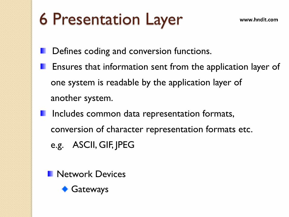
Defines coding and conversion functions.
Ensures that information sent from the application layer of
one system is readable by the application layer of
another system.
Includes common data representation formats,
conversion of character representation formats etc.
e.g. ASCII, GIF, JPEG
6 Presentation Layer
Network Devices
Gateways

Presentation layer
The presentation layer is responsible for translation,
compression, and encryption.
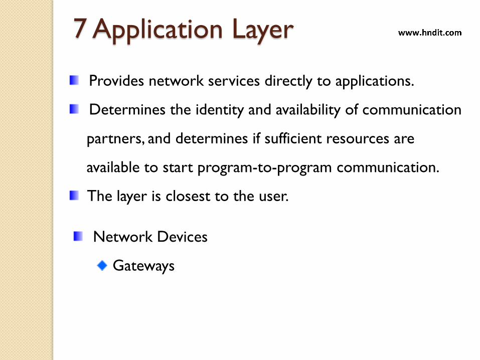
Provides network services directly to applications.
Determines the identity and availability of communication
partners, and determines if sufficient resources are
available to start program-to-program communication.
The layer is closest to the user.
7 Application Layer
Network Devices
Gateways
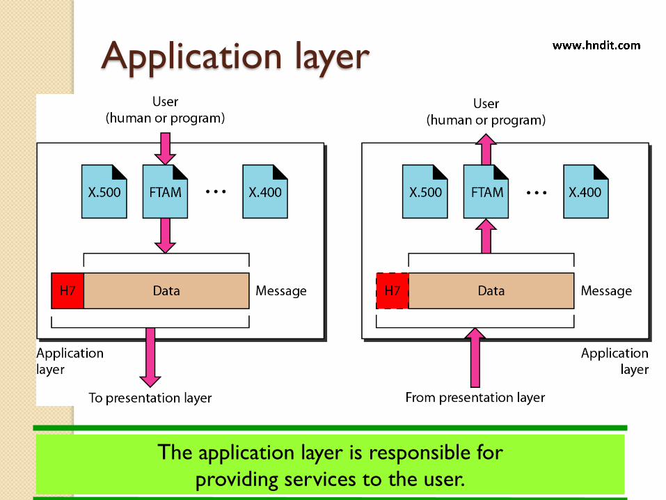
Application layer
The application layer is responsible for
providing services to the user.

The OSI Environment
71

Summary
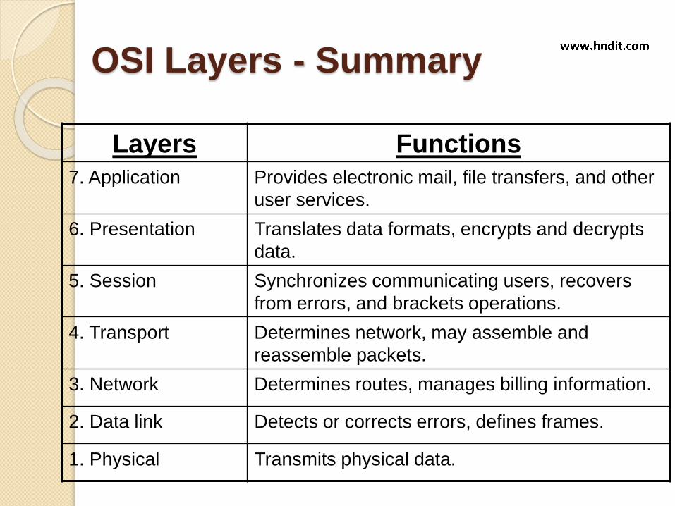
OSI Layers - Summary
Layers Functions
7. Application Provides electronic mail, file transfers, and other
user services.
6. Presentation Translates data formats, encrypts and decrypts
data.
5. Session Synchronizes communicating users, recovers
from errors, and brackets operations.
4. Transport Determines network, may assemble and
reassemble packets.
3. Network Determines routes, manages billing information.
2. Data link Detects or corrects errors, defines frames.
1. Physical Transmits physical data.
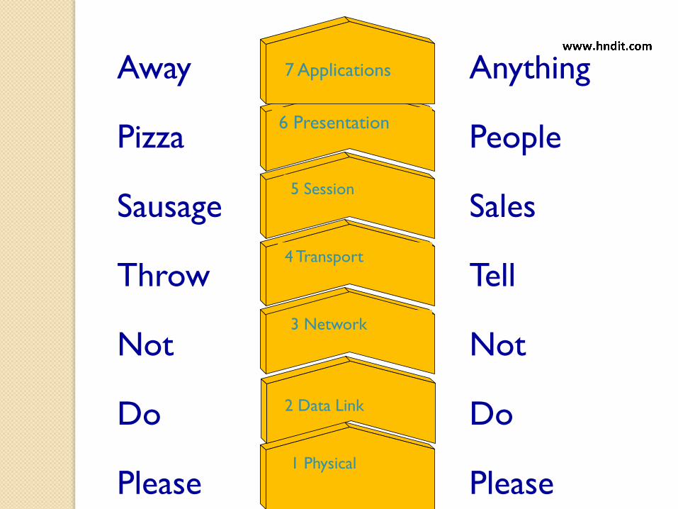
1 Physical
2 Data Link
3 Network
4 Transport
5 Session
6 Presentation
7 ApplicationsAway
Pizza
Sausage
Throw
Not
Do
Please
Anything
People
Sales
Tell
Not
Do
Please

Host layers
7 Application
6 Presentation
5 Session
4 Transport
3 Network
2 Data Link
1 Physical
These layers only
exist in the source
and destination host
computers.
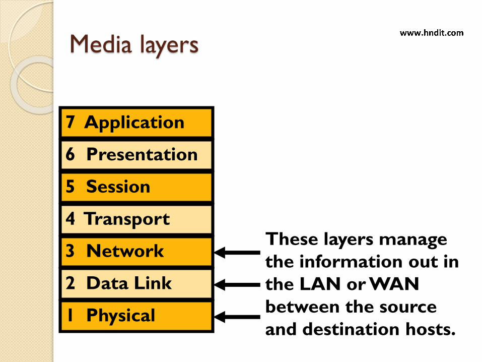
Media layers
7 Application
6 Presentation
5 Session
4 Transport
3 Network
2 Data Link
1 Physical
These layers manage
the information out in
the LAN or WAN
between the source
and destination hosts.
Advantages
Dividing the network into seven layers provides the following advantages:
◦ It breaks network communication into smaller, more manageable parts.
◦ It standardizes network components to allow multiple vendor development and support.
◦ It allows different types of network hardware and software to communicate with each other.
◦ It prevents changes in one layer from affecting other layers.
◦ It divides network communication into smaller parts to make learning it easier to understand.
TCP/IP - Transmission Control
Protocol / Internet ProtocolProtocol Architecture
Why another model ?
79
Although the OSI reference model is universally
recognized, the historical and technical open
standard of the Internet is Transmission Control
Protocol / Internet Protocol (TCP/IP).
The TCP/IP reference model and the TCP/IP
protocol stack make data communication
possible between any two computers, anywhere
in the world, at nearly the speed of light.
Why another model ?
80
The U.S. Department of Defense (DoD) created the
TCP/IP reference model because it wanted a
network that could survive any conditions, even a
nuclear war.

TCP/IP Modal
The historical and technical standard of
the Internet.
The TCP/IP model has the following four
layers:
◦ Application layer
◦ Transport layer
◦ Internet layer
◦ Network access layer
TCP / IP Protocol Suite
The layers in the TCP/IP protocol suite do not exactly match
those in the OSI model. The original TCP/IP protocol suite was
defined as having four layers: host-to-network, internet, transport,
and application. However, when TCP/IP is compared to OSI, we
can say that the TCP/IP protocol suite is made of five layers:
physical, data link, network, transport, and application.
Origin – DARPA (Defense Advanced Research Projects
Agency) implemented on ARPANET (Advanced Research
Project Agency Network) which evolved into the
Internet.

The Application Layer
83
The application
layer of the
TCP/IP model
handles high-
level protocols,
issues of
representation,
encoding, and
dialog control.

The Application Layer application layer that handles issues of
representation, encoding, and dialog
control.
◦ Some of the most commonly used application
layer protocols include the following:
File Transfer Protocol (FTP)
Hypertext Transfer Protocol (HTTP)
Simple Mail Transfer Protocol (SMTP)
Domain Name System (DNS)
Trivial File Transfer Protocol (TFTP)
The Transport Layer
85
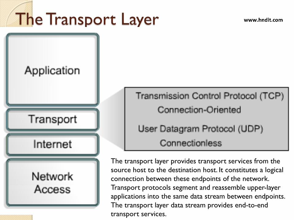
The transport layer provides transport services from the
source host to the destination host. It constitutes a logical
connection between these endpoints of the network.
Transport protocols segment and reassemble upper-layer
applications into the same data stream between endpoints.
The transport layer data stream provides end-to-end
transport services.
The Transport Layer
The transport layer deals with the quality of service issues of reliability, flow control, and error correction. One of its protocols, the transmission control protocol (TCP), provides excellent and flexible ways to create reliable, well-flowing, low-error network communications.
The common transport layer protocols include:
◦ Transport Control Protocol (TCP)
◦ User Datagram Protocol (UDP)
The Internet Layer
87
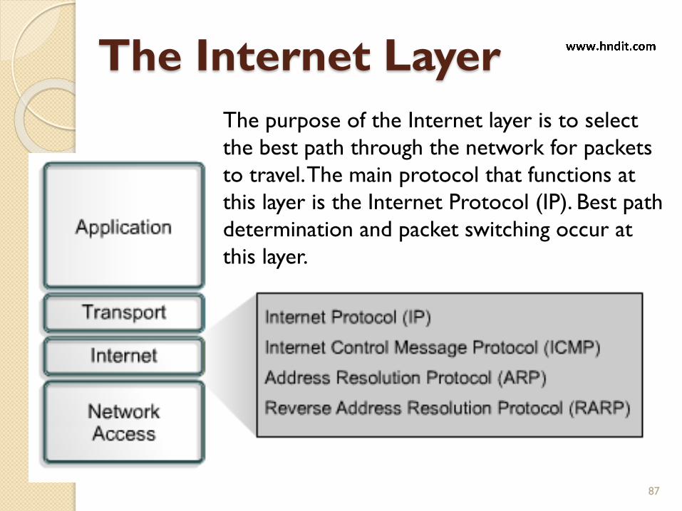
The purpose of the Internet layer is to select
the best path through the network for packets
to travel. The main protocol that functions at
this layer is the Internet Protocol (IP). Best path
determination and packet switching occur at
this layer.
The Internet Layer
The purpose of the Internet layer is to divide TCP
segments into packets and send them from any
network.
The packets arrive at the destination network
independent of the path they took to get there.
The specific protocol that governs this layer is called
the Internet Protocol (IP).
Best path determination and packet switching occur
at this layer.
The Network Access Layer
89
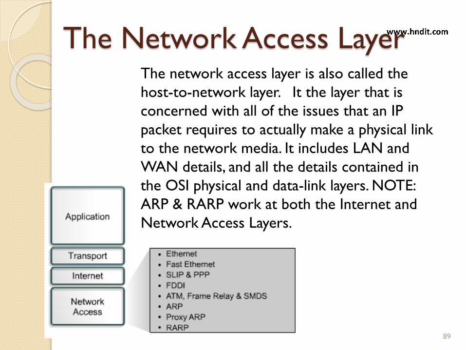
The network access layer is also called the
host-to-network layer. It the layer that is
concerned with all of the issues that an IP
packet requires to actually make a physical link
to the network media. It includes LAN and
WAN details, and all the details contained in
the OSI physical and data-link layers. NOTE:
ARP & RARP work at both the Internet and
Network Access Layers.
The Network Access Layer
The name of the network access layer is very
broad and somewhat confusing. It is also known
as the host-to-network layer.
This layer is concerned with all of the
components, both physical and logical, that are
required to make a physical link.
It includes the networking technology details,
including all the details in the OSI physical and
data link layers.
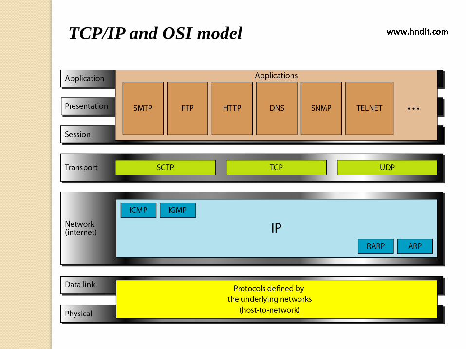
TCP/IP and OSI model

Comparing TCP/IP & OSI Models
92
NOTE: TCP/IP transport layer using UDP does not always guarantee
reliable delivery of packets as the transport layer in the OSI model
does.
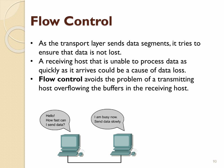
Flow Control
93
• As the transport layer sends data segments, it tries to
ensure that data is not lost.
• A receiving host that is unable to process data as
quickly as it arrives could be a cause of data loss.
• Flow control avoids the problem of a transmitting
host overflowing the buffers in the receiving host.
TCP Transmission Control Protocol (TCP) is a connection-oriented
transport layer protocol that provides reliable full-duplex data
transmission.
TCP is part of the TCP/IP protocol stack. In a connection-oriented
environment, a connection is established between both ends before the
transfer of information can begin.
TCP is responsible for breaking messages into segments, reassembling
them at the destination station, resending anything that is not received,
and reassembling messages from the segments. TCP supplies a virtual
circuit between end-user applications.
The protocols that use TCP include:
FTP (File Transfer Protocol)
HTTP (Hypertext Transfer Protocol)
SMTP (Simple Mail Transfer Protocol)
Telnet 94

TCP Segment Format
95
UDP
User Datagram Protocol (UDP) is the connectionless transport protocol
in the TCP/IP protocol stack.
UDP is a simple protocol that exchanges datagrams, without
acknowledgments or guaranteed delivery. Error processing and
retransmission must be handled by higher layer protocols.
UDP uses no windowing or acknowledgments so reliability, if needed, is
provided by application layer protocols. UDP is designed for applications
that do not need to put sequences of segments together.
The protocols that use UDP include:
TFTP (Trivial File Transfer Protocol)
SNMP (Simple Network Management Protocol)
DHCP (Dynamic Host Control Protocol)
DNS (Domain Name System)
96

UDP Segment Format
97
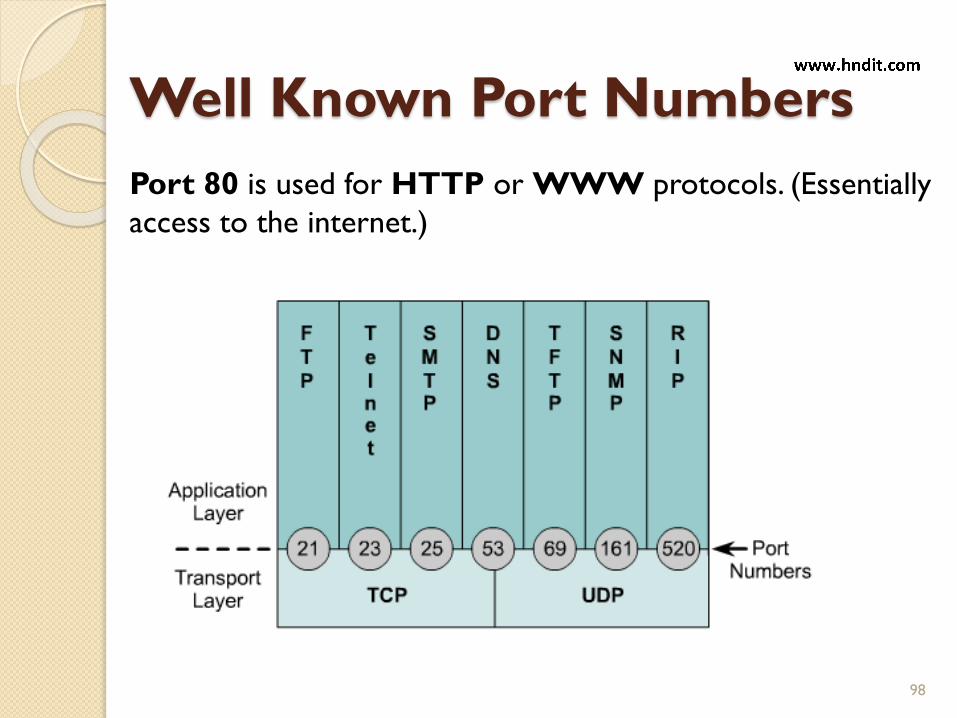
Well Known Port Numbers
98
Port 80 is used for HTTP or WWW protocols. (Essentially
access to the internet.)

END