lcos-based mode shaper for few-mode fiber · lcos-based mode shaper for few-mode fiber ... gb/s...
TRANSCRIPT

LCoS-based mode shaper for few-mode fiber Johannes von Hoyningen-Huene,1,2,* Roland Ryf,1 and Peter Winzer1
1Bell Laboratories, Alcatel-Lucent, 791 Holmdel-Keyport Rd, Holmdel, NJ, 07733, USA 2Chair for Communications, University of Kiel, Kaiserstr. 2, 24143 Kiel, Germany
Abstract: Spatial light modulation can be used to address specific fiber modes, as required in mode-division multiplexed systems. We theoretically compare phase-only spatial light modulation to a combination of amplitude and phase spatial light modulation in terms of insertion loss and crosstalk for a fiber supporting 11 LP modes. We experimentally demonstrate selective mode excitation using a Liquid Crystal on Silicon (LCoS) spatial light modulator configured to as phase and amplitude modulator.
©2013 Optical Society of America
OCIS codes: (060.0060) Fiber optics and optical communications; (060.4230) Multiplexing; (060.2340) Fiber optics components.
References and links 1. P. J. Winzer, “Optical networking beyond WDM,” IEEE Photon. J. 4(2), 647–651 (2012). 2. R.-J. Essiambre, G. Kramer, P. J. Winzer, G. J. Foschini, and B. Goebel, “Capacity limits of optical fiber
networks,” J. Lightwave Technol. 28(4), 662–701 (2010). 3. S. Chandrasekhar, A. H. Gnauck, X. Liu, P. J. Winzer, Y. Pan, E. C. Burrows, T. F. Taunay, B. Zhu, M.
Fishteyn, M. F. Yan, J. M. Fini, E. M. Monberg, and F. V. Dimarcello, “WDM/SDM transmission of 10 x 128-Gb/s PDM-QPSK over 2688-km 7-core fiber with a per-fiber net aggregate spectral-efficiency distance product of 40,320 km⋅b/s/Hz,” Opt. Express 20(2), 706–711 (2012).
4. J. Sakaguchi, B. J. Puttnam, W. Klaus, Y. Awaji, N. Wada, A. Kanno, T. Kawanishi, K. Imamura, H. Inaba, K. Mukasa, R. Sugizaki, T. Kobayashi, and M. Watanabe, “19-core fiber transmission of 19x100x172-Gb/s SDM-WDM-PDM-QPSK signals at 305Tb/s,” in Proc. Optical Fiber Communication Conference (OFC/NFOEC’12), PDP5C.1 (2012).
5. H. Takara, A. Sano, T. Kobayashi, H. Kubota, H. Kawakami, A. Matsuura, Y. Miyamoto, Y. Abe, H. Ono, K. Shikama, Y. Goto, K. Tsujikawa, Y. Sasaki, I. Ishida, K. Takenaga, S. Matsuo, K. Saitoh, M. Koshiba, and T. Morioka, “1.01-Pb/s (12 SDM/222 WDM/456 Gb/s) crosstalk-managed transmission with 91.4-b/s/Hz aggregate spectral efficiency,” in Proc. European Conference on Optical Communication (ECOC’12), Th.3.C.1 (2012).
6. R. Ryf, R.-J. Essiambre, A. Gnauck, S. Randel, M. A. Mestre, C. Schmidt, P. Winzer, R. Delbue, P. Pupalaikis, A. Sureka, T. Hayashi, T. Taru, and T. Sasaki, “Space-division multiplexed transmission over 4200 km 3-core microstructured fiber,” in Proc. Optical Fiber Communication Conference (OFC/NFOEC’12), PDP5C.2 (2012).
7. P. J. Winzer and G. J. Foschini, “MIMO capacities and outage probabilities in spatially multiplexed optical transport systems,” Opt. Express 19(17), 16680–16696 (2011).
8. S. Schöllmann, S. Soneff, and W. Rosenkranz, “10.7 Gb/s Over 300 m GI-MMF using a 2 x 2 MIMO system based on mode group diversity multiplexing,” in Proc. Optical Fiber Communication Conference (OFC/NFOEC’07), OTuL2S (2007).
9. C. P. Tsekrekos and A. M. J. Koonen, “Mode-selective spatial filtering for increased robustness in a mode group diversity multiplexing link,” Opt. Lett. 32(9), 1041–1043 (2007).
10. H. Chen, B. H.P.A. van den, and T. Koonen, “30Gbit/s 3 × 3 optical mode group division multiplexing system with mode-selective spatial filtering,” in Proc. Optical Fiber Communication Conference (OFC/NFOEC’11), OWB1 (2011).
11. P. M. Krummrich and K. Petermann, “Evaluation of potential optical amplifier concepts for coherent mode multiplexing,” in Proc. Optical Fiber Communication Conference (OFC/NFOEC’11), OMH5 (2011).
12. R. Ryf, R.-J. Essiambre, J. von Hoyningen-Huene, and P. Winzer, “Analysis of mode-dependent gain in Raman amplified few-mode fiber,” in Proc. Optical Fiber Communication Conference (OFC/NFOEC’12), OW1D.2 (2012).
13. M. Salsi, D. Peyrot, G. Charlet, S. Bigo, R. Ryf, N. K. Fontaine, M. A. Mestre, S. Randel, X. Palou, C. Bolle, B. Guan, G. Le Cocq, L. Bigot, and Y. Quiquempois, “A six-mode erbium-doped fiber amplifier,” in Proc. European Conference on Optical Communication (ECOC’12), Th.3.A.6 (2012).
14. E. Ip, N. Bai, Y. Huang, E. Mateo, F. Yaman, M. Li, S. Bickham, S. Ten, Y. Luo, G. Peng, G. Li, T. Wang, J. Linares, C. Montero, and V. Moreno, “6x6 MIMO transmission over 50+25+10 km heterogeneous spans of few-mode fiber with inline erbium-doped fiber amplifier,” in Proc. Optical Fiber Communication Conference (OFC/NFOEC’12), OTu2C.4 (2012).
#190545 - $15.00 USD Received 14 May 2013; revised 2 Jul 2013; accepted 6 Jul 2013; published 19 Jul 2013(C) 2013 OSA 29 July 2013 | Vol. 21, No. 15 | DOI:10.1364/OE.21.018097 | OPTICS EXPRESS 18097

15. D. Askarov and J. M. Kahn, “Design of multi-mode erbium-doped fiber amplifiers for low mode-dependent gain,” in Proc. IEEE Photonics Society Summer Topical Meeting Series, 220–221 (2012).
16. Q. Kang, E. Lim, Y. Jung, J. Sahu, F. Poletti, S. Alam, and D. Richardson, “Modal gain control in a multimode erbium doped fiber amplifier incorporating ring doping,” in Proc. European Conference on Optical Communication (ECOC’12), P1.05 (2012).
17. Y. Jung, S. Alam, Z. Li, A. Dhar, D. Giles, I. P. Giles, J. K. Sahu, F. Poletti, L. Grüner-Nielsen, and D. J. Richardson, “First demonstration and detailed characterization of a multimode amplifier for space division multiplexed transmission systems,” Opt. Express 19(26), B952–B957 (2011).
18. A. Li, A. Al Amin, X. Chen, and W. Shieh, “Reception of mode and polarization multiplexed 107-Gb/s CO-OFDM signal over a two-mode fiber,” in Proc. Optical Fiber Communication Conference (OFC/NFOEC’11), PDPB8 (2011).
19. R. C. Youngquist, J. L. Brooks, and H. J. Shaw, “Two-mode fiber modal coupler,” Opt. Lett. 9(5), 177–179 (1984).
20. R. Ryf, M. A. Mestre, A. Gnauck, S. Randel, C. Schmidt, R.-J. Essiambre, P. Winzer, R. Delbue, P. Pupalaikis, A. Sureka, Y. Sun, X. Jiang, D. Peckham, A. H. McCurdy, and R. Lingle, “Low-loss mode coupler for mode-multiplexed transmission in few-mode fiber,” in Proc. Optical Fiber Communication Conference (OFC/NFOEC’12), PDP5B.5 (2012).
21. S. G. Leon-Saval, A. Argyros, and J. Bland-Hawthorn, “Photonic lanterns: A study of light propagation in multimode to single-mode converters,” Opt. Express 18(8), 8430–8439 (2010).
22. N. K. Fontaine, R. Ryf, S. G. Leon-Saval, and J. Bland-Hawthorn, “Evaluation of photonic lanterns for lossless mode-multiplexing,” in Proc. European Conference on Optical Communication (ECOC’12), Th.2.D.6 (2012).
23. R. Ryf, N. K. Fontaine, M. A. Mestre, S. Randel, X. Palou, C. Bolle, A. H. Gnauck, S. Chandrasekhar, X. Liu, B. Guan, R.-J. Essiambre, P. J. Winzer, S. Leon-Saval, J. Bland-Hawthorn, R. Delbue, P. Pupalaikis, A. Sureka, Y. Sun, L. Grüner-Nielsen, R. V. Jensen, and R. Lingle, “12 x 12 MIMO transmission over 130-km few-mode fiber,” in Proc. Frontiers in Optics Conference (FiO’12), FW6C.4 (2012).
24. S. Berdagué and P. Facq, “Mode division multiplexing in optical fibers,” Appl. Opt. 21(11), 1950–1955 (1982). 25. R. Ryf, S. Randel, A. H. Gnauck, C. Bolle, A. Sierra, S. Mumtaz, M. Esmaeelpour, E. C. Burrows, R.-J.
Essiambre, P. J. Winzer, D. W. Peckham, A. H. McCurdy, and R. Lingle, “Mode-division multiplexing over 96 km of few-mode fiber using coherent 6 × 6 MIMO processing,” J. Lightwave Technol. 30(4), 521–531 (2012).
26. W. Q. Thornburg, B. J. Corrado, and X. D. Zhu, “Selective launching of higher-order modes into an optical fiber with an optical phase shifter,” Opt. Lett. 19(7), 454–456 (1994).
27. W. Mohammed, M. Pitchumani, A. Mehta, and E. G. Johnson, “Selective excitation of the LP11 mode in step index fiber using a phase mask,” SPIE Opt. Eng. 45(7), 74602–74602 (2006).
28. C. Koebele, M. Salsi, D. Sperti, P. Tran, P. Brindel, H. Mardoyan, S. Bigo, A. Boutin, F. Verluise, P. Sillard, M. Astruc, L. Provost, F. Cerou, and G. Charlet, “Two mode transmission at 2×100 Gb/s, over 40 km-long prototype few-mode fiber, using LCOS-based programmable mode multiplexer and demultiplexer,” Opt. Express 19(17), 16593–16600 (2011).
29. E. Alon, V. Stojanovic, J. M. Kahn, S. Boyd, and M. Horowitz, “Equalization of modal dispersion in multimode fiber using spatial light modulators,” in Proc. of Global Telecommunications Conference (GLOBECOM '04), IEEE, vol. 2, 1023–1029 (2004).
30. J. Carpenter, B. C. Thomsen, and T. D. Wilkenson, “Mode division multiplexing of modes with the same azimuthal index,” IEEE Photon. Technol. Lett. 24(21), 1969–1972 (2012).
31. D. Marcuse, Theory of Dielectric Optical Waveguides (Academic, 1974). 32. D. Gloge, “Weakly guiding fibers,” Appl. Opt. 10(10), 2252–2258 (1971). 33. O. Wallner, W. R. Leeb, and P. J. Winzer, “Minimum length of a single-mode fiber spatial filter,” J. Opt. Soc.
Am. A 19(12), 2445–2448 (2002). 34. S. Ramachandran, N. Bozinovic, P. Gregg, S. Golowich, and P. Kristensen, “Optical vortices in fibres: A new
degree of freedom for mode multiplexing,” in Proc. European Conference on Optical Communication (ECOC’12), Tu.3.F.3 (2012).
35. H. Kogelnik and P. J. Winzer, “Modal birefringence in weakly guiding fibers,” J. Lightwave Technol. 30(14), 2240–2245 (2012).
36. H. Kogelnik, Guided-Wave Optoelectronics (Springer, 1988).
1. Introduction
In order to support the exponential growth of the Internet traffic demand in fiber optic communication systems, multiple degrees of freedom for the optical signal have been exploited over the past decades [1], such as increased symbol rates, wavelength-division multiplexing (WDM), polarization-division multiplexing (PDM) and higher-order modulation formats. However, recent studies that include fiber nonlinearity into the Shannon capacity framework [2] have shown that the transmission capacity over single mode fiber (SMF) is rapidly approaching fundamental limits. To overcome the capacity limit, a new degree of freedom must be exploited for multiplexing, and space has been identified as the next
#190545 - $15.00 USD Received 14 May 2013; revised 2 Jul 2013; accepted 6 Jul 2013; published 19 Jul 2013(C) 2013 OSA 29 July 2013 | Vol. 21, No. 15 | DOI:10.1364/OE.21.018097 | OPTICS EXPRESS 18098

accessible dimension [1]. In space-division multiplexing (SDM), a number of signals are sent over parallel uncoupled or coupled transmission paths. SDM can be used in combination with other known techniques like WDM, PDM, and higher-order modulation formats, and two SDM approaches are currently being investigated:
• In multi-core fibers (MCFs) several fiber cores are arranged within the same cladding and are being used as different, either coupled or uncoupled communication channels [3–6].
• In few-mode fibers (FMFs) the size and the refractive index profile of a single fiber core is chosen such that several propagation modes are supported by the fiber. Owing to their mutual orthogonality, these modes, albeit coupled by fiber imperfections, can then be used as individual communication channels through multiple-input multiple-output (MIMO) digital signal processing [7].
Note that the full set of modes supported by the FMF has to be addressed individually at transmitter and receiver in order to achieve reliable long-distance transmission [7], in contrast to shorter-reach mode-group multiplexing applications that have been reported for multimode fibers [8–10]. To enable mode multiplexing systems that can replace SMF systems with parallel fibers both few-mode amplifiers [11–17] and mode multiplexers and demultiplexers [18–29] have to be developed or enhanced.
The purpose of a mode multiplexer is to couple light from a set of SMF sources into different FMF propagation modes (or to specific unitary combinations thereof). At the receiver a mode demultiplexer is required to separate the different modes of the FMF into a set of parallel SMF. Over the past years, several multiplexer and demultiplexer techniques have been reported. These techniques include physically stressed fiber [18,19], spot couplers [20], photonic lanterns [21–23], 3D-waveguides [23], and spatial phase shaping of the optical profile with glass plates [24–27]. Alternatively to the above static mode shaping techniques, dynamic and adaptive spatial light modulators (SLMs), such as reflective liquid crystal on silicon (LCoS) devices can also be used for mode shaping [28–30]. Regarding the latter, mode multiplexers that shape the phase but not the amplitude of the spatial optical profile to be coupled into the FMF have so far been used. In this work we theoretically investigate and experimentally demonstrate beam shaping of both phase and amplitude using a LCoS modulator and discuss its relevance for coupling into higher-order modes of few-mode fibers.
2. Modes of a step-index few-mode fiber
The guided modes of a step-index profile fiber are determined by the diameter of the core, the refractive index profile of the fiber, and the wavelength of the optical signal [31,32]. In a SMF these parameters are chosen such that only a single spatial mode (consisting of two degenerate polarization modes) can propagate along the fiber. All other modes do not propagate over extended distances in the fiber. Their power is radiated off quickly and cannot be received at the end of the fiber [33]. However, with increased core diameter, increased refractive index difference between core and cladding, or decreased wavelength, an increasing number of higher-order modes can also be guided in the fiber. In this work we assume a step-index fiber with 16-µm core diameter, a refractive index of 1.46, and a relative difference between core and cladding refractive index of 0.5%. At 1550 nm, and as shown in Fig. 1, this fiber supports six true waveguide modes, namely the twofold degenerate HE11 mode as well as the TE01, TM01, and the twofold degenerate HE21. The twofold degenerate HE11-modes (labeled a and b in Fig. 1) are also known as the two polarization modes making up the fiber’s fundamental mode. Due to its Gaussian-like intensity profile, its flat phase front, and its linear polarization, the HE11 can be excited with high efficiency by using linearly polarized Gaussian beams. The twofold degenerate HE21-modes (labeled a and b in Fig. 1), as well as TE01 and TM01 have a donut-shaped intensity profile and a polarization distribution that changes across the beam profile. In contrast to the fundamental mode, these
#190545 - $15.00 USD Received 14 May 2013; revised 2 Jul 2013; accepted 6 Jul 2013; published 19 Jul 2013(C) 2013 OSA 29 July 2013 | Vol. 21, No. 15 | DOI:10.1364/OE.21.018097 | OPTICS EXPRESS 18099
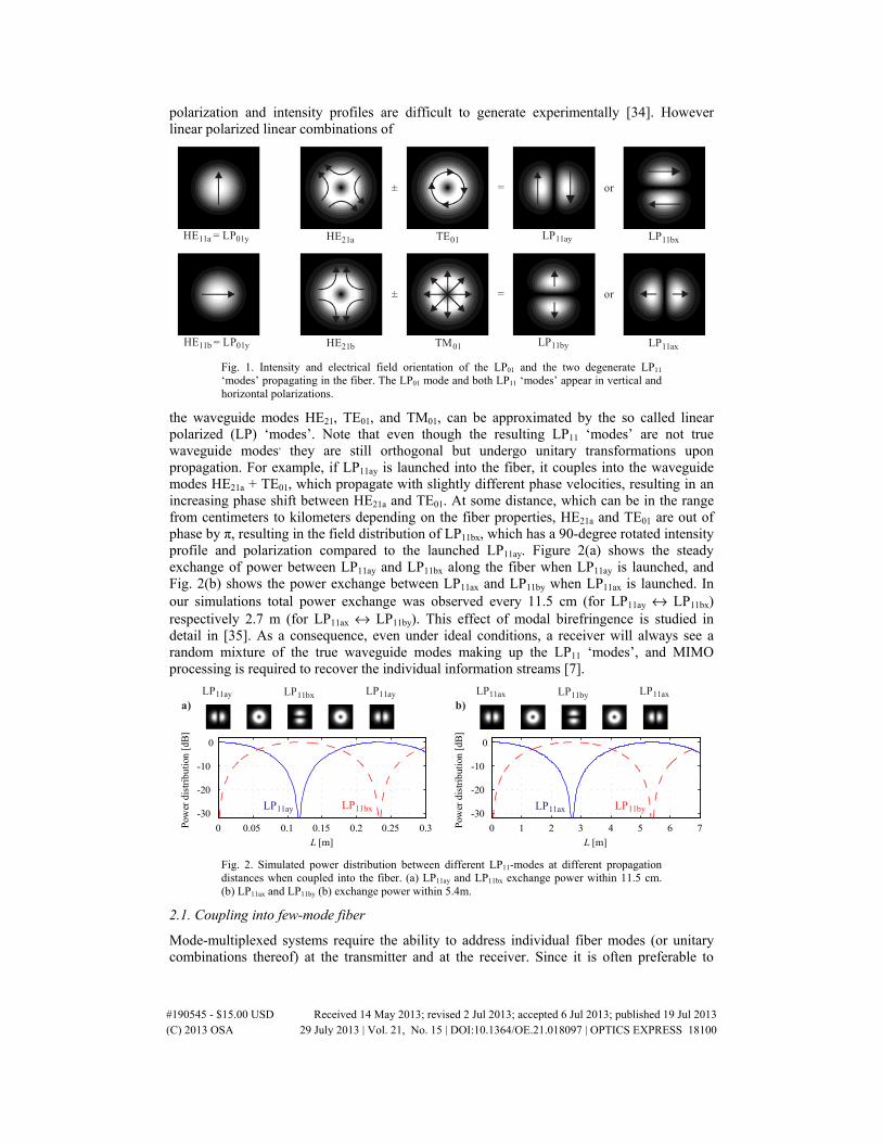
polarization and intensity profiles are difficult to generate experimentally [34]. However linear polarized linear combinations of
LP 11ayHE21a
HE21b
TE01
TM01
LP11bx
LP11by LP11ax
±
±
=
=
or
or
HE11a = LP01y
HE11b = LP01y
Fig. 1. Intensity and electrical field orientation of the LP01 and the two degenerate LP11 ‘modes’ propagating in the fiber. The LP01 mode and both LP11 ‘modes’ appear in vertical and horizontal polarizations.
the waveguide modes HE21, TE01, and TM01, can be approximated by the so called linear polarized (LP) ‘modes’. Note that even though the resulting LP11 ‘modes’ are not true waveguide modes, they are still orthogonal but undergo unitary transformations upon propagation. For example, if LP11ay is launched into the fiber, it couples into the waveguide modes HE21a + TE01, which propagate with slightly different phase velocities, resulting in an increasing phase shift between HE21a and TE01. At some distance, which can be in the range from centimeters to kilometers depending on the fiber properties, HE21a and TE01 are out of phase by π, resulting in the field distribution of LP11bx, which has a 90-degree rotated intensity profile and polarization compared to the launched LP11ay. Figure 2(a) shows the steady exchange of power between LP11ay and LP11bx along the fiber when LP11ay is launched, and Fig. 2(b) shows the power exchange between LP11ax and LP11by when LP11ax is launched. In our simulations total power exchange was observed every 11.5 cm (for LP11ay ↔ LP11bx) respectively 2.7 m (for LP11ax ↔ LP11by). This effect of modal birefringence is studied in detail in [35]. As a consequence, even under ideal conditions, a receiver will always see a random mixture of the true waveguide modes making up the LP11 ‘modes’, and MIMO processing is required to recover the individual information streams [7].
LP 11ay LP11bx LP 11ay
0 0.05 0.1 0.15 0.2 0.25 0.3
-30
-20
-10
0
L [m]
Pow
er d
istr
ibut
ion
[dB
]
0 1 2 3 4 5 6 7
-30
-20
-10
0
L [m]
Pow
er d
istr
ibut
ion
[dB
]
LP 11ax LP11by LP 11ax
a) b)
LP 11ay LP11bx LP 11ax LP11by
Fig. 2. Simulated power distribution between different LP11-modes at different propagation distances when coupled into the fiber. (a) LP11ay and LP11bx exchange power within 11.5 cm. (b) LP11ax and LP11by (b) exchange power within 5.4m.
2.1. Coupling into few-mode fiber
Mode-multiplexed systems require the ability to address individual fiber modes (or unitary combinations thereof) at the transmitter and at the receiver. Since it is often preferable to
#190545 - $15.00 USD Received 14 May 2013; revised 2 Jul 2013; accepted 6 Jul 2013; published 19 Jul 2013(C) 2013 OSA 29 July 2013 | Vol. 21, No. 15 | DOI:10.1364/OE.21.018097 | OPTICS EXPRESS 18100

excite and detect LP spatial profiles instead of the true waveguide modes directly, mode shaping needs to take place before coupling into the fiber to adapt the usually single-mode source to the amplitude and phase profile of the respective LP ‘mode’. For lower-order modes, the phase profile is the most prominent differentiator between modes. For example [24–28], use only a simple phase pattern to launch a specific mode. When only the phase profile but not the amplitude profile of the incident light is matched to the desired fiber LP ‘mode’ not all the optical power will couple into this target LP ‘mode’. Some fraction of the incident power will then couple into other – typically higher order – LP ‘modes’. If these unwanted LP ‘modes’ are not supported by the FMF the mismatch of the amplitude profile upon coupling only results in an insertion loss. However, if propagation of these unwanted LP ‘modes’ is supported by the fiber as well in the context of a mode multiplexing system, the corresponding spurious power will reach the receiver and act as (non-unitary, hence capacity-degrading) crosstalk [7,22]. Furthermore, lack of amplitude shaping results in higher insertion loss for each individually shaped mode.
The insertion loss and crosstalk of the mode coupler is evaluated according to the arrangement shown in Fig. 3, where a fiber with a core diameter of 30-µm is assumed, that has a V-value of 8.87 and supports 11 LP ‘modes’. This is done, because modal crosstalk by phase-only ‘mode’ shaping only arises when modes higher than LP11 are supported by the FMF. Vertical polarized light from a SMF source is collimated to a Gaussian beam with waist radius W0 and a plane phase front.
+ + + + + ...0π
Gaussian beam with plane phase front
Phase profileof SLM
(here: LP11
)
Phase modulated
beam
LP11
LP31
LP51
LP12
LP32
Excited LP 'modes' in FMF
2W0 30-µm
Fig. 3. Setup to evaluate insertion loss and modal crosstalk for phase-only LP ‘mode’ shaping and coupling into FMF (core area depicted in blue).
The incident Gaussian beam can be expressed by its electrical and magnetic field
2 2
4Gauss 20 0 0
2 1( ,, ) expo
y
xE e
yx y
W W
μπ
+= ⋅
⋅ ⋅ − ⋅
(1)
2 2
04Gauss 2
0 0
2 1( , ) exp ,x
o
HW
ex y
x yWπ μ+= − ⋅ ⋅ ⋅ − ⋅
(2)
where the total optical beam power is normalized to 1. The phase profile of the beam is changed by the spatial light modulator. Assuming a plane phase front of the incident beam, the phase profile of the SLM is defined by the phase profile of the LP(µ,υ) ‘mode’ to be shaped:
( )( )LP( , )( , ) exp arg , ) .(f x y yi E xμ ν= ⋅ (3)
Thus, the electromagnetic field of the shaped beam is given by:
Gauss( , ) ( , ) ,x y E f x yE = ⋅
(4)
#190545 - $15.00 USD Received 14 May 2013; revised 2 Jul 2013; accepted 6 Jul 2013; published 19 Jul 2013(C) 2013 OSA 29 July 2013 | Vol. 21, No. 15 | DOI:10.1364/OE.21.018097 | OPTICS EXPRESS 18101

Gauss( , ) ( , ) ,x y H f x yH = ⋅
(5)
Neglecting reflection effects at the fiber surface, the optical field in the FMF can be described as a sum of guided and radiated LP ‘modes’ each weighted with a complex coupling coefficient C(µ,υ) [36]
( , ) LP( . ) ,( , ) µµ
µC EE x y ν νν
⋅=
(6)
( , ) LP( . )( , ) .µµ
µC HH x y ν νν
⋅=
(7)
The electro-magnetic field of the LP ‘mode’ is normalized as
LP( , ) LP( , )( , ) ( , ) 1.zx y H x y dx dyE eμ ν μ ν∗
∞ ∞
−∞ −∞
=×
(8)
The coupling coefficient C(µ,υ) from an electro-magnetic field ( , )E x y
and ( , )H x y
into a LP
’mode’, defined by its electro-magnetic field LP( , ) ( , )E x yμ ν
and LP( , ) ( , ),H x yμ ν
can be
calculated as
( )( , ) LP( , ) LP( , )( , ) ( , )( , ) ( , ) ,zC H x y x y H dx dyE x y y eE xμ ν μ ν μ ν∗ ∗
∞ ∞
−∞ −∞
× += ×
(9)
where * denotes complex conjugation and × is the outer product. The coupling efficiency from the incident beam power to the power of an excited LP ‘mode’ is finally given by
2
( , ) ( , ) .Cμ ν μ νη = (10)
As an example, we calculate coupling efficiencies for a FMF with a core diameter of 30 µm that has a V-number of 8.87 and supports 11 different LP ‘modes’. The waist radius W0 of the Gaussian beam is varied from 5 to 30 µm. Figure 4(a) shows the coupling efficiencies into several LP ‘modes’ supported by the fiber, if phase shaping for the LP11 ‘mode’ is used. Both the insertion loss into the desired LP11 ‘mode’ and the crosstalk into other LP ‘modes’ depend on the waist radius W0 of the Gaussian beam. The optimal waist radius W0,opt in terms of minimal insertion loss for LP11 is 13.4 µm. Figure 4(a) also depicts the waist radius with lowest maximal crosstalk into an individual mode. However, at this waist radius LP31 and LP12 are excited with similar coupling efficiency, so the total power in undesired LP ‘modes’ is higher compared to W0,opt. This simulation is repeated for all supported LP ‘modes’ of the FMF. Figure 4(b) shows insertion loss and crosstalk values better than −30 dB visualized in grey scale (brightness of area is proportional to absolute coupling coefficient). For each desired LP ‘mode’ the optimal waist radius W0,opt in terms of insertion loss is retrieved. With phase-only spatial shaping of a Gaussian beam, coupling efficiency values between −0.1 dB (LP01) and −3.2 dB (LP51) are obtained. The highest crosstalk from a beam with LP11 phase profile into the fiber LP31 ‘mode’ is −12 dB. Note that no crosstalk between LP01 and LP11 is observed, thus phase-only ‘mode’ shaping is sufficient for an FMF supporting only these LP ‘modes’. In a FMF supporting more LP ‘modes’ phase-only shaping results in crosstalk, which degrades the system performance. When the SLM allows spatial attenuation to also match the amplitude profile of the launch signal to that of the desired LP ‘mode’ the crosstalk of the mode shaper can be significantly reduced. In this case the complex spatial shaping profile is chosen as:
#190545 - $15.00 USD Received 14 May 2013; revised 2 Jul 2013; accepted 6 Jul 2013; published 19 Jul 2013(C) 2013 OSA 29 July 2013 | Vol. 21, No. 15 | DOI:10.1364/OE.21.018097 | OPTICS EXPRESS 18102

( )( ) LP( , )LP( , )
Gauss
( , )( , )( , ) exp arg ,1min
( ).
,
Ef x y i
xE
x yx y
yE μ ν
μ ν
=
⋅ ⋅ (11)
The clipping of the amplitude profile to ≤ 1 takes into account that only spatial attenuation but no amplification is considered. This clipping is the only source of the residual crosstalk of the mode shaper. An alternative choice for the spatial shape profile is to normalize it to a maximum amplitude of 1. This would result in further reduced crosstalk but also significantly increased insertion loss, which should be avoided. We choose clipping as a good compromise
Des
ired
mod
e (m
ode
shap
er)
LP01
LP11
LP21
LP02
LP31
LP12
LP41
LP22
LP03
LP51
LP32
LP 01
LP 11
LP 21
LP 02
LP 31
LP 12
LP 41
LP 22
LP 03
LP 51
LP 32
Fiber mode
b)a) -0.1 -26 -24 11.0 µm
-1.5 -12 -18 13.4 µm
-2.1 -17 15.0 µm
-1.1 13.4 µm
-2.6 -20 16.2 µm
-23 -22 -1.8 -22 -14 13.8 µm
-2.9 17.1 µm
-25 -1.8 15.0 µm
-19 -1.1 15.2 µm
-3.2 18.2 µm
-1.8 17.4 µm
-18 -23
Coupling efficiency [dB] at W0,opt
W0,opt
5 10 15 20 25 30
-22
-20
-18
-16
-14
-12
-10
-8
-6
-4
-2
0
Waist radius of Gaussian beam (µm)
Cou
plin
g ef
fici
ency
(dB
)
LP LP11 31→
LP LP11 51→
LP LP11 11→
LP LP11 12→LP LP11 32→
minimal crosstalk
optimal insertion loss
Fig. 4. (a) Simulated coupling efficiency for phase-only ‘mode’ shaping assuming the coupling of a target LP11 ‘mode’ into a FMF supporting 11 LP ‘modes’. (b) Coupling efficiency (showing insertion loss and crosstalk) for all LP ‘mode’ shaped beams into all supported fiber LP ‘modes’.
Des
ired
mod
e (m
ode
shap
er)
LP01
LP11
LP21
LP02
LP31
LP12
LP41
LP22
LP03
LP51
LP32
LP 01
LP 11
LP 21
LP 02
LP 31
LP 12
LP 41
LP 22
LP 03
LP 51
LP 32
Fiber mode
b)a) -0.2 11.7 µm
-2.6 -19 -24 -28 13.8 µm
-3.3 -23 15.3 µm
-2.1 13.5 µm
-3.8 -25 16.4 µm
-27 -26 -2.9 -22 13.8 µm
-4.1 17.1 µm
-28 -2.9 14.9 µm
-22 -2.0 14.9 µm
-4.4 17.9 µm
-2.9 16.8 µm
W0,opt
5 10 15 20 25 30
-20
-18
-16
-14
-12
-10
-8
-6
-4
-2
0
Waist radius of Gaussian beam (µm)
Cou
plin
g ef
fici
ency
(dB
)
LP LP11 11→
LP LP11 31→
LP LP11 12→
optimal insertion loss
Coupling efficiency [dB] at W0,opt
Fig. 5. (a) Simulated coupling efficiencies for complex (phase and amplitude) ‘mode’ shaping assuming the coupling of a target LP11 ‘mode’ into a FMF supporting 11 LP ‘modes’. (b) Coupling efficiency (showing insertion loss and crosstalk) for all LP ‘mode’ shaped beams into all supported fiber LP ‘modes’.
#190545 - $15.00 USD Received 14 May 2013; revised 2 Jul 2013; accepted 6 Jul 2013; published 19 Jul 2013(C) 2013 OSA 29 July 2013 | Vol. 21, No. 15 | DOI:10.1364/OE.21.018097 | OPTICS EXPRESS 18103

between insertion loss and crosstalk. Figures 5(a) and 5(b) show simulation results for coupling efficiency and crosstalk when complex (phase and amplitude) shaping is applied instead of phase-only spatial light modulation. Due to the spatial attenuation the insertion loss is increased by between 0.1 dB and 1.2 dB for the various modes. But the crosstalk into undesired modes is significantly reduced to a maximal value of −19 dB instead of −12 dB with phase-only mode shaping. Thus, the net improvement is approximately 6 dB. The simulation results also show, that the optimal waist radius of the incident beam increases slightly for the lower-order LP ‘modes’ and decreases for higher-order LP ‘modes’.
2.2. Amplitude shaping using a LCoS modulator
Spatial light modulation of phase and amplitude can be realized by combining a spatial phase modulator (eq. glass plates with different thicknesses, or a LCoS modulator) with an additional structure that provides spatial attenuation; devices that perform both functions in a single step are difficult to realize. A more practical approach is to use a phase-only modulator
Pinhole
SMF
LCoS
FMF
f1 f1 f2 f2
L1 L2
2·rcore
Fig. 6. Optical setup for complex spatial light modulation and coupling into FMF
in combination with a spatial filter, consisting in its simplest form of a two-lens system with a pinhole located in between. The spatial filter converts spatial phase-modulation (PM) to spatial amplitude-modulation (AM) and thus generates complex light modulation if an adequate phase profile is used. The concept is shown in Fig. 6. The optical signal from a SMF is collimated generating a Gaussian-like beam. The optical beam is reflected on a LCoS modulator, where its optical phase profile can be adjusted by the LCoS pixels. For efficient fiber coupling the beam has to be adapted to the fiber core radius rcore (see Figs. 4(a)-4(b) and 5(a)-5(b)) using a double telecentric system consisting of two lenses (L1, L2). The optical profile at the FMF surface is scaled down by ( f1 / f2) relative to the profile on the LCoS modulator, where f1 and f2 are the focal lengths of the lenses. By placing a pinhole in the Fourier plane, which is located in the common focal plane between the lenses, a low pass filter for spatial frequency can be implemented. Regions on the LCoS modulator having a relative slow change in phase profile will generate low spatial frequency that are transferred to the field profile at the fiber facet at a corresponding position. On the other hand, region where the phase changes rapidly, will generate large spatial frequencies that are attenuated by the spatial filter and the amplitude at the corresponding position on the fiber facet is attenuated. The diameter of the pinhole is chosen so that the patterns with highest spatial frequency (i.e. checkerboard pattern) are blocked. In Fig. 6, for example, the part of the incident beam that is phase shaped with a checkerboard pattern is highly attenuated. The use of checkerboard pattern is advantageous because it generates the largest spatial frequency that the LCoS device is capable of, therefore maximizing the spatial frequency transfer for the desired phase and amplitude profile. By using a checkerboard with two independent pixel values the intensity and the phase of a reflected beam can be adjusted. While the intensity of the beam can be controlled by the difference of the pixel values, the phase shift can be set by
#190545 - $15.00 USD Received 14 May 2013; revised 2 Jul 2013; accepted 6 Jul 2013; published 19 Jul 2013(C) 2013 OSA 29 July 2013 | Vol. 21, No. 15 | DOI:10.1364/OE.21.018097 | OPTICS EXPRESS 18104

the mean of the individual phase shifts. For complex spatial light modulation the LCoS surface can be divided into small areas, each having a checkerboard pattern with two pixel values for amplitude and phase shaping.
3. Experimental mode shaping using a LCoS modulator
Experimental investigation of mode shaping was performed according to the setup presented in Fig. 6. A SMF continuous-wave laser source with 5.4 dBm power is collimated to a Gaussian beam with a waist radius W0 = 314 μm. After beam splitting (BS, 50/50), one part is spatially modulated by the LCoS modulator, the other part is used for coherent phase measurement in a Michelson interferometer type arrangement. The LCoS modulator (Aurora Systems ASI6010, optimized for 1550 nm) provides phase modulation of 1080x1920 pixels with 8 µm pitch. At 1550 nm the phase shift is adjustable in a 2π range. The incident Gaussian beam illuminates around 80x80 pixels on the LCoS modulator, which is sufficient for complex spatial light modulation. The FMF has a core diameter of 16 µm and supports only LP01 and LP11 ‘modes’. If a FMF is used that supports more LP ‘modes’ a larger beamsize and more LCoS pixel might be required. In addition the focal length of the lenses and the pinhole have to be adjusted to ensure, that the phase pattern of the highest order ‘mode’ still passes the pinhole, while a checkerboard pattern with a phase shift of π still leads to attenuation.
3.1. Device characteristics and calibration
To verify the capabilities of the complex SLM setup the optical profile is detected with an infrared sensitive InGaAs sensor array. For this purpose a different lens combination (f1 = 75 mm, f2 = 200 mm) is chosen to magnify the optical profile. The calibration setup is shown in Figs. 7(a) and 7(b) for two exemplary LCoS patterns. Our measurements revealed several imperfections of the SLM:
• The phase shift is not exactly linearly proportional to the pixel values written to the device.
• A small intensity modulation of about 1.5 dB is observed in addition to the phase modulation at phase shifts around π.
• The phase shift of a pixel is affected not only by its own voltage but partially also by that of the neighboring pixels.
Hence, to calibrate the complex light modulation of the LCoS modulator, we wrote a checkerboard pattern formed by two independent phase values to the LCoS modulator. The spatially modulated beam and the reference beam are projected on the sensor array at the
Mirror
SMFfrom laser source
Sen
sor
arra
y
Mirror
SMFfrom laser source
a) b)
LC
oS
LC
oS
L1 L
2Mask L
1L
2Mask
Sen
sor
arra
y
Fig. 7. Optical setup for calibrating the LCoS spatial phase and amplitude modulation characteristics. With uniform LCoS modulator pattern the modulated and the reference beam pass the mask (a). With checkerboard phase pattern higher harmonics in the spatial Fourier transform of the shaped beam are blocked by the mask (b).
interferometer output. By varying both phase values of the checkerboard pattern, the observed light amplitude is changed by factor aLCoS and the phase is changed by φLCoS. In the general
#190545 - $15.00 USD Received 14 May 2013; revised 2 Jul 2013; accepted 6 Jul 2013; published 19 Jul 2013(C) 2013 OSA 29 July 2013 | Vol. 21, No. 15 | DOI:10.1364/OE.21.018097 | OPTICS EXPRESS 18105

case, where the phase front of both beams is not exactly parallel to the sensor array, the complex envelope of the electrical fields LCoS ( , )E x y , Ref ( , )E x y on the sensor surface can be
expressed as:
( )LCoS LCoS 0 LCoS,x LCoS,y LCoS( ,( , ) exp) ( ) ,E a E x y jx y k y kx ϕ+= ⋅ ⋅ ⋅ + ⋅ (12)
( )Ref Ref Ref,x Ref,y Ref( , ) (( , ) exp ) ,x y k y kE E x y j x ϕ= ⋅ ⋅ + ⋅ + (13)
where LCoS ( , )E x y corresponds to the beam profile that is reflected from the LCoS modulator
and Ref ( , )E x y to the unshaped reference beam that is reflected from the mirror. 0 ( , )E x y is the
field profile of the reflected from a blank LCoS modulator (e.g. without shaping), kLCoS,x, kLCoS,y, kRef,x, kRef,y depend on the angle between the phase front of both beam and the sensor surface in x- and y-direction. The phase offset φRef of the reference beam is constant, while the phase offset of the shaped beam φLCoS depends on the LCoS pixel values. Since the sensor array cannot detect the optical phase, it detects the intensity profiles
0 LC
2 22 2LCoS LCoS LCoSoS 0( , ) (( , ) , ) ( , ) ,I a I x y E x y a E x yx y ⋅ ⋅= =∝ (14)
2
Ref efR ( , ) ( , ) ,I E x yx y ∝ (15)
if only one beam illuminates the sensor array at once (the other beam is blocked in this case). If the shaped beam is superposed with the reference beam, the intensity profile captured by the sensor consists of lines of constructive and destructive interference. The measured intensity on the sensor is shown in Fig. 7(a) and can be expressed as
{ }
2
2
LCoS Ref
*LCoS Ref LCoS R
2
ef
( , ) ( , )
( , ) ( , ) 2 ( , )
( , )
Re ,( , )
I E x y E x y
E x y E x y E x y E y
x
x
y +
= + ⋅ ⋅+
∝ (16)
( )2LCoS LCo0 R S x y 0ef 0 Ref( , ) ( , ) 2 ( , ) ( ,( , ) co) ,sI x y I x y I xI x y a y I xa yy x k k ϕ+= ⋅ ⋅ Δ + Δ ++
(17)
with x LCoS,x Ref,x ,k k k−Δ = y LCoS,y Ref,yk k k−Δ = and 0 LCoS Ref .ϕ ϕ ϕ= − The optical components
(lenses, mirror, LCoS modulator) are adjusted so that the interference profile has only vertical lines with a periodicity of about 0.5 mm ( xkΔ ≈4π mm−1, ykΔ ≈0 mm−1). By applying a
checkerboard pattern to the LCoS modulator, the amplitude and the position of the interference lines change according to Eq. (17). Figure 8(a) shows horizontal cross sections of the intensity patterns captured on the sensor. Intensity curves of the reference beam, the shaped beam, and the interference of both are detected. The attenuation and the phase shift of this pixel pair can be retrieved by minimizing the following function:
( )LCoS LCoS
2LCoS 0 LCoSRef 0 Ref 0,
( ) ( ) 2min ( ) ( )( .) cos xax
I x I x I x I xI x a a x kϕ
ϕ − −− ⋅ ⋅ ⋅ ⋅ Δ +
⋅
(18)
Figure 8(b) shows graphically how the weighted cosine is fitted to the intensity profile of the interference. This phase and attenuation estimation is done for all possible combinations of the two pixel values.
#190545 - $15.00 USD Received 14 May 2013; revised 2 Jul 2013; accepted 6 Jul 2013; published 19 Jul 2013(C) 2013 OSA 29 July 2013 | Vol. 21, No. 15 | DOI:10.1364/OE.21.018097 | OPTICS EXPRESS 18106

-6 -4 -2 0 2 4 6x [mm]
Opt
ical
inte
nsity
(a.
u.)
-6 -4 -2 0 2 4 6x [mm]
Opt
ical
inte
nsity
(a.
u.)
a) b)2LCoS 0 Ref( (· ( ) )) I x I xI x a −−
( )I x
( )0 RefLCoS x 02 ( ) (· · · ·cos ·)x I x xa kI Δ +
0( )I xRef ( )I x
φ
Fig. 8. a) Optical intensity of one camera sensor row. Overlay of measured profiles of the beam reflected by the mirror and the LCoS modulator and the interference of both. b) Cosine function fitted to measured profile to estimate amplitude and phase of the spatially modulated beam.
Figure 9(a) shows a contour plot of the resulting attenuation aLCoS and Fig. 9(b) shows the contour plot of the phase shift φLCoS. The measurements reveal that the phase can be varied in a range of 2π and the attenuation in a range of 16 dB.
Pixel value 1
Pix
el v
alue
2
0 dB
0 dB
a)
Pixel value 1
Pix
el v
alue
2
b)
0
-16 dB
-16 dB
1 100
1
00
1
-π
aLCoS
φLCoS
-2π
Fig. 9. Normalized attenuation aLCoS (a) and phase shift φLCoS (b) for possible pixel value pairs for the checker board phase pattern generated by the LCoS modulator.
3.2 Mode shaping using spatial phase modulation
If phase-only mode shaping is used, only a phase jump in vertical or horizontal direction is applied to match the Gaussian input beam to the LP11 ‘mode’ shape. In this case the width of the incident beam should be approximately the width of the desired LP ‘mode’. Experimental images of the modulated profiles of the LP01 and both degenerate LP11 ‘modes’ with vertical polarization before fiber launching are shown in Fig. 10. The upper row of images gives the intensity patterns and the lower row gives the phase patterns, as obtained through interference with the reference beam in the Michelson setup of Figs. 7(a) and 7(b). The phase shift of π between both halves of the LP11 ‘mode’ is clearly visible.
#190545 - $15.00 USD Received 14 May 2013; revised 2 Jul 2013; accepted 6 Jul 2013; published 19 Jul 2013(C) 2013 OSA 29 July 2013 | Vol. 21, No. 15 | DOI:10.1364/OE.21.018097 | OPTICS EXPRESS 18107

Mod
ulat
ed b
eam
Mod
. bea
m +
ref
.
LP01 LP11a LP11b
0 π
0
π
LC
os p
atte
rn
Fig. 10. Measured intensity profiles after mode shaping for LP01 and LP11 with both vertical and horizontal orientations of the phase jump, without (upper row) and with (lower row) Michelson interference with a reference beam.
3.3. Mode shaping using spatial phase and amplitude modulation
For the demonstration of the complex SLM structure, the incident beam widened much more. The corresponding intensity image without modulation is depicted in Fig. 11(a). The complex modulation profile is given by Eq. (11). This required modulation profile is divided into small regions equivalent to 2x2 pixels on the LCoS modulator. For each region a checkerboard with 2x2 pixels (the smallest possible checkerboard size) with the required pair of pixel values is calculated. Figure 11(b) shows the pattern that is written to the LCoS modulator. In regions with high attenuation, neighboring pixels have a phase difference of approximately π, while neighboring pixels have similar values in regions with less attenuation. In the right half of the shaped area the mean phase shift is π/2 and in the left half it is 3π/2. Since the incident beam is much wider than the LP11 ‘mode’ to be shaped, significant power is lost within the areas of high attenuation. Figure 11(c) shows the intensity profile after complex SLM that fits more precisely to the desired LP11a ‘mode’. The interference of the shaped beam with the reference beam is depicted in Fig. 11(d) and visualizes the phase jump of π between both LP11a parts.
a) b) c) d)
Fig. 11. Captured image of beam profile before modulation (a), phase shift pattern written to the LCoS modulator (b), intensity profile after LP11a modulation without (c) and with interference (d).
Figures 12(a) and 12(b) show the horizontal and vertical cross-sections of the measured intensity profiles with phase-only (PM) and additional amplitude modulation (AM + PM) together with the simulated curve. The intensity and the diameter are normalized in each case.
#190545 - $15.00 USD Received 14 May 2013; revised 2 Jul 2013; accepted 6 Jul 2013; published 19 Jul 2013(C) 2013 OSA 29 July 2013 | Vol. 21, No. 15 | DOI:10.1364/OE.21.018097 | OPTICS EXPRESS 18108

While both profiles fit quite good to the theoretical profile in horizontal direction, the optical profile using PM is significantly larger in vertical direction than the measured profile of AM + PM and theory. Thus, higher crosstalk into other modes can be expected with the measured PM profile compared to the AM + PM profile.
-1.5 -1 -0.5 0 0.5 1 1.50
0.2
0.4
0.6
0.8
1
x r/core
Nor
mal
ized
inte
nsity
-1.5 -1 -0.5 0 0.5 1 1.50
0.2
0.4
0.6
0.8
1
Nor
mal
ized
inte
nsityTheoryAM+PM
PM
Theory
AM+PMPM
y r/core
a) b)
Fig. 12. Horizontal (a) and vertical (b) cross-section of the measured LP11 intensity profiles with phase-only modulation, complex modulation and the theoretical curve.
3.4 Fiber Coupling Results
For launching the LP11 mode into the fiber, the setup according to Fig. 13 is used. The optical beam is vertically polarized at the transmitter side. The incident beam power onto the LCoS modulator is 0.20 dBm and the optical power before fiber launching is −4.7 dBm. After spatial light modulation the beam is demagnified with two lenses with focal length of 200 mm and 9.5 mm to fit the FMF dimension. All optical components and the fiber are carefully aligned in three dimensions and two tilt angles. Slight misalignments result in crosstalk into other than desired modes. The FMF with a length of 5 cm is fixed straight and without significant stress. After propagation the outcoming beam is enlarged again with a 9.5-mm lens and a 300-mm lens and detected with the infrared sensitive sensor. The reference beam bypasses the fiber and is interfered with the shaped beam after the fiber with a second BS in a Mach-Zehnder structure. Power measurement is also used at one side of this BS (reference beam blocked in this case). A second polarization filter allows signal detection in vertical and horizontal polarizations, respectively. Figures 14(a)-14(f) show the measured profiles of LP01, LP11a, and LP11b together with the measured optical power values in both polarizations. A difference of the insertion loss of 3 dB between LP01 and LP11 modes can be seen. Possible reasons are that the incident beam diameter fits more to LP01 than to LP11 and that the required phase jump for LP01 leads to additional attenuation in the non-perfectly aligned optical setup. By looking at
LC
oS
Mirror
FMF (5 cm)
Opticalpowermeter
Mirror
Sens
or a
rray
Pol. filter
Pol. filter
Unmodulated reference beam
BS BS
SMFfrom laser source
Fig. 13. Setup for a FMF coupling experiment of LP01, LP11a, and LP11b.
the different polarizations after the fiber separately, the impact of the mode coupling as explained in section 2 is evident. Since only vertical polarized light is launched, the optical profiles with horizontal polarization filter after the fiber corresponds to cross coupling within
#190545 - $15.00 USD Received 14 May 2013; revised 2 Jul 2013; accepted 6 Jul 2013; published 19 Jul 2013(C) 2013 OSA 29 July 2013 | Vol. 21, No. 15 | DOI:10.1364/OE.21.018097 | OPTICS EXPRESS 18109

the fiber. Noteworthy is that even for such a short fiber (5 cm), some coupling between LP11ay and LP11bx is observed. The coupling between LP11by and LP11ax is however much smaller. Qualitatively, this observation is in agreement with the simulated coupling values in Figs. 2(a) and 2(b) because the length of power exchange of LP11ay and LP11bx is in the range of centimeters, while for LP11by and LP11ax are expected to exchange power in the range of meters, which is significantly longer than the used fiber length of 5 cm. The detection of small portions of LP11bx in the case of LP01 and LP11b ‘mode’ shaping could be explained with nonperfect alignment of the components (small amount of LP11ay is launched as well) and limited selectivity of the polarization filters (LP11by is detected as LP11bx).
Ver
tical
pol
ariz
atio
nH
oriz
onta
l pol
ariz
atio
nLP shaped01 LP shaped11a LP shaped11b
LP detected01y
LP detected11ay
LP detected11by
P = -14.0 dBm P = -17.0 dBm P = -16.9 dBm
LP detected11bx
LP detected11bx
LP + detected11ax
LP11bx
P = -35.4 dBm P = -30.0 dBm P = -35.6 dBm
a) b) c)
f)e)d)
Fig. 14. Measured intensity profile of shaped LP01 (a + d), LP11a (b + e) and LP11b (c + f) after 5 cm of FMF with vertical (a-c) and horizontal (d-f) polarization filter at the receiver.
4. Conclusion
We analyzed the crosstalk properties of mode multiplexers based on spatial light modulators, and numerically showed that the crosstalk into higher order modes can significantly be reduced by using amplitude shaping in addition to the already discussed phase-only shaping of the optical profile. Complex spatial light modulation comes at the price of slightly increased insertion loss and system complexity but improves the performance of mode multiplexing systems supporting a large number of modes. A practical realization for a complex spatial-light modulator is proposed and experimentally demonstrated. The proposed device uses a LCoS phase-only spatial light modulator, and a simple spatial filter. The device is adaptive which is advantageous in early stage of research where the flexibility to support multiple different fiber types is required. For practical application in optical communication, the use of fixed phase plates instead of the LCoS modulator might be preferable in terms of loss, physical size and costs, at the expense of adaptability Finally, we theoretically analyzed and experimentally demonstrated the presence of coupling between the LP11 modes of a few-mode fiber even for a very short 5 cm long fiber. The capability to precisely excite fiber modes could be of interest in other fields like optical sensing or image transfer over multimode fibers.
#190545 - $15.00 USD Received 14 May 2013; revised 2 Jul 2013; accepted 6 Jul 2013; published 19 Jul 2013(C) 2013 OSA 29 July 2013 | Vol. 21, No. 15 | DOI:10.1364/OE.21.018097 | OPTICS EXPRESS 18110