le-270a can / lin le-270a - lineeye · model le-270a sd-2gx 2g byte sd card 3a ... efficient...
TRANSCRIPT
Interface
Connector
Number of Channels
Protocol
Baud Rate
CAN Monitor
LIN Monitor
Mode
Measurement start/stop
Filter
Time Stamp
CAN: Comfort to ISO11898/ ISO11519-2 standard. TJA1050/ TJA1054 (switchable)LIN: Comfort to ISO9141 standard. TJA1020
DSUB 25 pin male connector #4-40UNC
2 channels of CAN or LIN, or 1 CAN and 1 LIN
CAN, Device Net, LIN (Rev1.1, 1.2, 1.3, 2.0, 2.1)
CAN: Max 1Mbps LIN: Max 20Kbps (arbitrary)
Standard/ Expansion format. Support bit timing settings.
Recording Type Ring Buffer (continuous) mode, Fixed Buffer (full stop) mode
Remote mode (with PC); Data Logger mode (PC-less)
Control from PC, Start/Stop switch, Auto-Power run, Specify date and time.
Record only specified ID frames.
Display on PC Real-time display, Watch data display(display specified data of each ID)
“Hr:Min:Sec”, “Min:Sec:x1ms”, 9 digits: “100μs”, “10μs”, “1μs” (selectable)
LED 4 of two-color LED: Power/Error, Test/Record, CH1/CH2, User-defined U1/U2
USB2.0 Port Mini-B connector. High speed supported.
Power *2
USB bus power or external DC (DC8-32V), AC adapter: “3A-183WP09” (center +)
Power consumption: Max. 1.3W, 0.1W/ DC12V when powering off
Run time during power failure 1 sec
In operation: -20~+60℃ In storage: -20~+60℃, 5 – 85%RH (No condensation)Ambient Temperature, Humidity
Dimensions, weight 86(W)×130(D)×30(H) mm, approx. 230g
OS:Windows® XP/Vista/7 PC: PC/AT compatiblePC Environment
*1: LINEEYE does not warrant the operation of SD/SDHC cards of other manufacturers.*2: AC adapter is sold separately. In the Remote mode (with PC), LE-270A runs by the USB bus power. In the Logger mode (PC-less),
you need to have the optional AC adapter (3A-183WP09) or use the proper external power.
Data string up to 8 characters, specified remote frame (CAN), frame error (LIN), timer and counter, logic status of external signal, external trigger input.
Stop measurement (offset can be set), validates/invalidates trigger condition, control timer/counter, turn on/off the light of user-defined LED, output external signals, output trigger signals.
Trigger
Action
Condition
Retrieval function on PC
Trigger matched data, Error (Break, Sync, Parity, Checksum, Framing), Data: Specified ID (don’t care available), Data string (Up to 8 characters; don’t care and bit mask available), CAN Remote Data: Specified ID (don’t care available), Specified Time stamp, External signal
External Signal Input
Diginal/Analog 4 channelsRecording: At the time of receiving signals, or specified sampling cycle (1ms - 10min, 13steps)Diginal VIH 2V (Min.), VIL 0.5V (Max.)Analog Range: -16V to +16V, Accuracy: ±0.5%FS, A/D conversion: 15Ksps, Resolution: 10bit
Frame breaking is possible according to the data length of each ID or specified idle time.
Error Check Break:(LIN), Sync:(LIN), Parity:(LIN), Checksum:(CAN/LIN), Framing:(LIN)
MemoryPC: Max 8G byte on the HDD, PC-less: Capacity of the SD card
(Specify the file size as 128K /1M / 2M/ 4M / 8M byte)
Conversion Convert data into Text or CSV format and save.
SD/SDHC Card 2 – 8G byte *1
External Trigger Signal 1 Input, 2 Output (equipped in the measurement connector)
Switch One: RUN / STOP
®
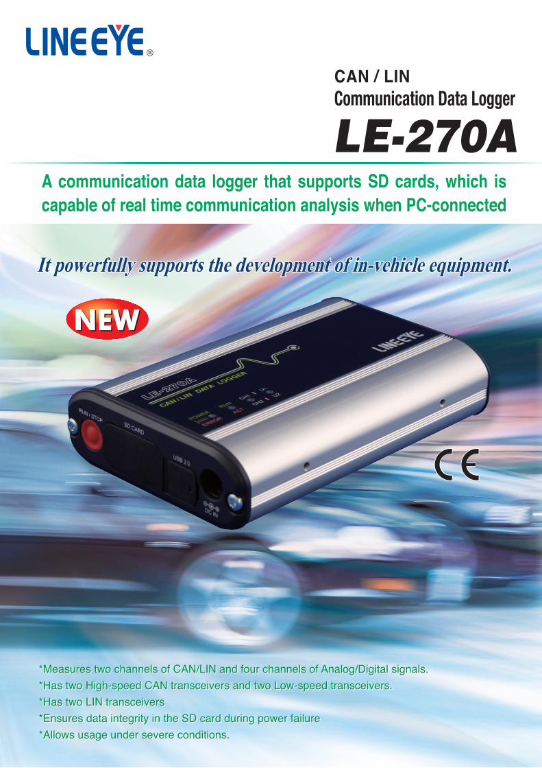
It powerfully supports the development of in-vehicle equipment.It powerfully supports the development of in-vehicle equipment.It powerfully supports the development of in-vehicle equipment.
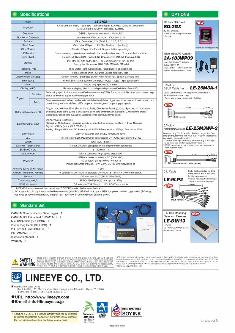
CAN/LIN Communication Data Logger…1CAN/LIN DSUB Cable (LE-25M3A-1)…1Mini USB cable (SI-US218)…1Power Plug Cable (SIH-2PG)…12G Byte SD Card (SD-2GX)…1PC Software CD…1Instruction Manual…1Warranty…1
Standard Set
DSUB Cable for LE-270A. Length: 1m. One side is Y terminal (MS) with mark tags. * Same as the cable packed with LE-270A.
CAN/LIN DSUB Cable 1m
Water-proofing DSUB cable for LE-270A. Length: 2m. One side is without terminal with mark tags. (Custom specification is available for specific length.)* Connectors or clips necessary for connecting to the object
to be measured are to be provided by the user.* DSUB connectors do not provide drip-proof performance
when not connected.
CAN/LIN Water-proof DSUB Cable
Probe cable with clips for CAN measurement and IC test clips for LIN measurement.* Cannot input/output external trigger
signal or external analog signal.
Clip Cable
Model LE-270A
SD-2GX2G byte SD Card
3A-183WP09Wide Input AC Adapter
*The photo is for illustrative purposes only.
Input: AC100~240V, 50/60HzOutput: DC9V, 2APlug: Center+, Outside diameter: 5.5mm, Inside diameter: 2.1mm
2G byte SD card.*Same as the card packed with LE-270A.
350mm
DB25 (female)
A communication data logger that supports SD cards, which is capable of real time communication analysis when PC-connected
LE-270ACommunication Data LoggerCAN / LIN
Specifications OPTIONS
LE-DIN13
DIN Rail Mounting Plate for LE-series.
To mount LE-150PS/LE-200PS/LE-270A on the 35mm DIN rail.
0.3m1.7m
DB25 water-proof model (female)
LE-25M3A-1
LE-25M3WP-2
LE-9LP2
0.7m 0.3m
DB25 (female) Y terminal
*Measures two channels of CAN/LIN and four channels of Analog/Digital signals.
*Has two High-speed CAN transceivers and two Low-speed transceivers.
*Has two LIN transceivers
*Ensures data integrity in the SD card during power failure
*Allows usage under severe conditions.
*Measures two channels of CAN/LIN and four channels of Analog/Digital signals.
*Has two High-speed CAN transceivers and two Low-speed transceivers.
*Has two LIN transceivers
*Ensures data integrity in the SD card during power failure
*Allows usage under severe conditions.
•All brand names and product names mentioned in this catalog are trademarks or registered trademarks of their respective companies. •Specifications and designs of products listed in this catalog are as of February 2012, and are subject to change without notice for improvement. •Colors of actual products may differ slightly from that listed due to printing condition. •This catalog may not be reprinted or duplicated, in part or in whole.©2012 by LINEEYE CO., LTD.
* LINEEYE CO., LTD. is a venture company founded by electronic equipment development members of the former Sekisui Chemical Co., Ltd. with investment from the Sekisui Venture Fund.
Printed in Japan
L-12203E/LE G
LINEEYE CO., LTD.Head Office/Sales Office Marufuku Bldg, 5F, 39-1 Karahashi Nishihiragaki-cho, Minami-ku, Kyoto, 601-8468 PHONE: 81-75-693-0161 FAX:81-75-693-0163
URL http://www.lineeye.comE-mail : [email protected]
Read the instruction manual provided with the product before use and use the product as explained in that manual. Using the product in ways not guaranteed in the manual, connecting it to systems outside of the specified ranges and remodeling can all cause trouble and damage. LINEEYE CO., LTD. will assume no responsibility whatsoever for trouble or damage arising because of unauthorized ways of use.
SAFETYWARNING
QR-00337ER-00094
CE (class A), EMC (EN 61326-1:2006)Standard
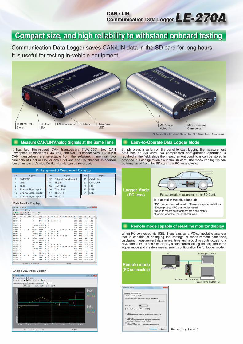
It has two High-speed CAN transceivers (TJA1050), two CAN Low-speed transceivers (TJA1054) and two LIN transceivers (TJA1020). CAN transceivers are selectable from the software. It monitors two channels of CAN or LIN, or one CAN and one LIN channel. In addition, four channels of Analog/Digital signals can be recorded.
Measure CAN/LIN/Analog Signals at the Same Time
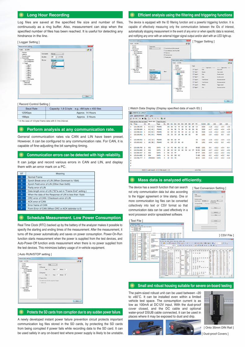
Log files are saved at the specified file size and number of files, continuously as a ring buffer. Also, measurement can stop when the specified number of files has been reached. It is useful for detecting any hindrance in the line.
Long Hour Recording
General communication rates via CAN and LIN have been preset. However, it can be configured to any communication rate. For CAN, it is capable of fine-adjusting the bit sampling timing.
Perform analysis at any communication rate.
The device is equipped with the ID filtering function and a powerful triggering function. It is capable of effectively measuring only the communication between the IDs of interest, automatically stopping measurement in the event of any error or when specific data is received, and notifying any error with an external trigger signal output and/or alert with an LED light-up.
Real Time Clock (RTC) backed up by the battery of the analyzer makes it possible to specify the starting and ending times of the measurement. After the measurement, it turns off the power automatically and saves on power consumption. Power-On-Run function starts measurement when the power is supplied from the test devices, and Auto-Power-Off function ends measurement when there is no power supplied from the test devices. This minimizes battery usage of in-vehicle equipment.
Schedule Measurement. Low Power Consumption
It can judge and record various errors in CAN and LIN, and display them with an error mark on a PC.
Communication errors can be detected with high reliability.
Mass data is analyzed efficiently.
The palm-sized robust unit can be used between –20 to +60˚C. It can be installed even within a limited vehicle test space. The consumption current is as low as 100mA at DC12V input. With the dust-proof cover closed, and the DC cable and optional water-proof DSUB cable connected, it can be used in places where it may be exposed to dust and drip.
Small and robust housing suitable for severe on-board testing
Compact size, and high reliability to withstand onboard testingCompact size, and high reliability to withstand onboard testingCommunication Data Logger saves CAN/LIN data in the SD card for long hours. It is useful for testing in-vehicle equipment.
Pin Assignment of Measurement Connector
[ Logger Setting ]
Meaning
Normal Frame
Synch Break error of LIN (When Dominant is 10bit)
Synch Field error of LIN (Other than 0x55)
Parity error of LIN
Data length error of LIN ("ID"is set in "Frame End" setting )
When the data of the Response of LIN is less than 1byte
CRC error of CAN / Checksum error of LIN
ACK error of CAN
Form Error of CAN (When CRC or ACK delimiter is 0)
Error frame of CAN
ST
Efficient analysis using the filtering and triggering functions
[ Auto RUN/STOP setting ]
[ Record Control Setting ]
*: In the case of 12 byte/ frame data with 0.1ms interval.
Capacity: 1.8 G byte e.g. :4M byte × 450 files
Approx. 14 Hours
Approx. 3 Hours
Baud Rate
125Kbps
1Mbps
[ Trigger Setting ]
A newly developed instant power failure prevention circuit protects important communication log files stored in the SD cards, by protecting the SD cards from being corrupted if power fails while recording data to the SD card. It can be used safely in any on-board test where power supply is likely to be unstable.
Protects the SD cards from corruption due to any sudden power failure.
[ Dust-proof Covers ]
[ Onto 35mm DIN Rail ]
[ Watch Data Display (Display specified data of each ID) ]
[ CSV File ]
[ Text File ]
The device has a search function that can search not only communication data but also according to the trigger agreement or time stamp. One or more communication log files can be converted collectively into text or CSV format so that communication data can be used effectively in a word processor and/or spreadsheet software.
[ Text Conversion Setting ]
*1: For attaching the optional DIN rail plate. Pitch: 70mm. Depth: 3.5mm (max).
M3 Screw Holes *1
Measurement Connector
RUN / STOP Switch
SD Card Slot
USB Connector DC Jack Two-color LED
Remote mode(PC connected)
When PC-connected via USB, it operates as a PC-connectable analyzer that is capable of changing the settings of measurement conditions, displaying measurement data in real time and recording continuously to a HDD from a PC. It can also display a communication log file acquired in the logger mode and create a measurement configuration file for logger mode.
Remote mode capable of real-time monitor display
[ Remote Log Setting ]
Connect to PC via USB
Developing DevicePC
Record in the HDD of PC
It is useful in the situations of:
Logger Mode(PC less) For automatic measurement into SD Cards
Simply press a switch on the panel to start logging the measurement data into an SD card. No complicated configuration operation is required in the field, since the measurement conditions can be stored in advance in a configuration file in the SD card. The measured log file can be transferred from the SD card to a PC for analysis.
Easy-to-Operate Data Logger Mode
*PC usage is not allowed.*Dusty places (PC cannot be used).*Need to record data for more than one month.*Cannot operate the analyzer well.
*There are space limitations.
CAN / LINCommunication Data Logger
[ Analog Waveform Display ]
Signal
BATTERY
GND
GND
External Signal Input 1
External Signal Input 2
External Signal Input 3
Pin
1
4
7
9
10
11
Signal
CAN2 High
Pin
CAN2 Low
GND
LIN1
LIN2
19
21
22
23
24
Signal
TRGIN
CAN1 High
CAN1 Low
TRGOT2
TRGOT1
Pin
14
External Signal Input 412
15
16
17
18
[ Data Monitor Display ]
It has two High-speed CAN transceivers (TJA1050), two CAN Low-speed transceivers (TJA1054) and two LIN transceivers (TJA1020). CAN transceivers are selectable from the software. It monitors two channels of CAN or LIN, or one CAN and one LIN channel. In addition, four channels of Analog/Digital signals can be recorded.
Measure CAN/LIN/Analog Signals at the Same Time
Log files are saved at the specified file size and number of files, continuously as a ring buffer. Also, measurement can stop when the specified number of files has been reached. It is useful for detecting any hindrance in the line.
Long Hour Recording
General communication rates via CAN and LIN have been preset. However, it can be configured to any communication rate. For CAN, it is capable of fine-adjusting the bit sampling timing.
Perform analysis at any communication rate.
The device is equipped with the ID filtering function and a powerful triggering function. It is capable of effectively measuring only the communication between the IDs of interest, automatically stopping measurement in the event of any error or when specific data is received, and notifying any error with an external trigger signal output and/or alert with an LED light-up.
Real Time Clock (RTC) backed up by the battery of the analyzer makes it possible to specify the starting and ending times of the measurement. After the measurement, it turns off the power automatically and saves on power consumption. Power-On-Run function starts measurement when the power is supplied from the test devices, and Auto-Power-Off function ends measurement when there is no power supplied from the test devices. This minimizes battery usage of in-vehicle equipment.
Schedule Measurement. Low Power Consumption
It can judge and record various errors in CAN and LIN, and display them with an error mark on a PC.
Communication errors can be detected with high reliability.
Mass data is analyzed efficiently.
The palm-sized robust unit can be used between –20 to +60˚C. It can be installed even within a limited vehicle test space. The consumption current is as low as 100mA at DC12V input. With the dust-proof cover closed, and the DC cable and optional water-proof DSUB cable connected, it can be used in places where it may be exposed to dust and drip.
Small and robust housing suitable for severe on-board testing
Compact size, and high reliability to withstand onboard testingCompact size, and high reliability to withstand onboard testingCommunication Data Logger saves CAN/LIN data in the SD card for long hours. It is useful for testing in-vehicle equipment.
Pin Assignment of Measurement Connector
[ Logger Setting ]
Meaning
Normal Frame
Synch Break error of LIN (When Dominant is 10bit)
Synch Field error of LIN (Other than 0x55)
Parity error of LIN
Data length error of LIN ("ID"is set in "Frame End" setting )
When the data of the Response of LIN is less than 1byte
CRC error of CAN / Checksum error of LIN
ACK error of CAN
Form Error of CAN (When CRC or ACK delimiter is 0)
Error frame of CAN
ST
Efficient analysis using the filtering and triggering functions
[ Auto RUN/STOP setting ]
[ Record Control Setting ]
*: In the case of 12 byte/ frame data with 0.1ms interval.
Capacity: 1.8 G byte e.g. :4M byte × 450 files
Approx. 14 Hours
Approx. 3 Hours
Baud Rate
125Kbps
1Mbps
[ Trigger Setting ]
A newly developed instant power failure prevention circuit protects important communication log files stored in the SD cards, by protecting the SD cards from being corrupted if power fails while recording data to the SD card. It can be used safely in any on-board test where power supply is likely to be unstable.
Protects the SD cards from corruption due to any sudden power failure.
[ Dust-proof Covers ]
[ Onto 35mm DIN Rail ]
[ Watch Data Display (Display specified data of each ID) ]
[ CSV File ]
[ Text File ]
The device has a search function that can search not only communication data but also according to the trigger agreement or time stamp. One or more communication log files can be converted collectively into text or CSV format so that communication data can be used effectively in a word processor and/or spreadsheet software.
[ Text Conversion Setting ]
*1: For attaching the optional DIN rail plate. Pitch: 70mm. Depth: 3.5mm (max).
M3 Screw Holes *1
Measurement Connector
RUN / STOP Switch
SD Card Slot
USB Connector DC Jack Two-color LED
Remote mode(PC connected)
When PC-connected via USB, it operates as a PC-connectable analyzer that is capable of changing the settings of measurement conditions, displaying measurement data in real time and recording continuously to a HDD from a PC. It can also display a communication log file acquired in the logger mode and create a measurement configuration file for logger mode.
Remote mode capable of real-time monitor display
[ Remote Log Setting ]
Connect to PC via USB
Developing DevicePC
Record in the HDD of PC
It is useful in the situations of:
Logger Mode(PC less) For automatic measurement into SD Cards
Simply press a switch on the panel to start logging the measurement data into an SD card. No complicated configuration operation is required in the field, since the measurement conditions can be stored in advance in a configuration file in the SD card. The measured log file can be transferred from the SD card to a PC for analysis.
Easy-to-Operate Data Logger Mode
*PC usage is not allowed.*Dusty places (PC cannot be used).*Need to record data for more than one month.*Cannot operate the analyzer well.
*There are space limitations.
CAN / LINCommunication Data Logger
[ Analog Waveform Display ]
Signal
BATTERY
GND
GND
External Signal Input 1
External Signal Input 2
External Signal Input 3
Pin
1
4
7
9
10
11
Signal
CAN2 High
Pin
CAN2 Low
GND
LIN1
LIN2
19
21
22
23
24
Signal
TRGIN
CAN1 High
CAN1 Low
TRGOT2
TRGOT1
Pin
14
External Signal Input 412
15
16
17
18
[ Data Monitor Display ]
Interface
Connector
Number of Channels
Protocol
Baud Rate
CAN Monitor
LIN Monitor
Mode
Measurement start/stop
Filter
Time Stamp
CAN: Comfort to ISO11898/ ISO11519-2 standard. TJA1050/ TJA1054 (switchable)LIN: Comfort to ISO9141 standard. TJA1020
DSUB 25 pin male connector #4-40UNC
2 channels of CAN or LIN, or 1 CAN and 1 LIN
CAN, Device Net, LIN (Rev1.1, 1.2, 1.3, 2.0, 2.1)
CAN: Max 1Mbps LIN: Max 20Kbps (arbitrary)
Standard/ Expansion format. Support bit timing settings.
Recording Type Ring Buffer (continuous) mode, Fixed Buffer (full stop) mode
Remote mode (with PC); Data Logger mode (PC-less)
Control from PC, Start/Stop switch, Auto-Power run, Specify date and time.
Record only specified ID frames.
Display on PC Real-time display, Watch data display(display specified data of each ID)
“Hr:Min:Sec”, “Min:Sec:x1ms”, 9 digits: “100μs”, “10μs”, “1μs” (selectable)
LED 4 of two-color LED: Power/Error, Test/Record, CH1/CH2, User-defined U1/U2
USB2.0 Port Mini-B connector. High speed supported.
Power *2
USB bus power or external DC (DC8-32V), AC adapter: “3A-183WP09” (center +)
Power consumption: Max. 1.3W, 0.1W/ DC12V when powering off
Run time during power failure 1 sec
In operation: -20~+60℃ In storage: -20~+60℃, 5 – 85%RH (No condensation)Ambient Temperature, Humidity
Dimensions, weight 86(W)×130(D)×30(H) mm, approx. 230g
OS:Windows® XP/Vista/7 PC: PC/AT compatiblePC Environment
*1: LINEEYE does not warrant the operation of SD/SDHC cards of other manufacturers.*2: AC adapter is sold separately. In the Remote mode (with PC), LE-270A runs by the USB bus power. In the Logger mode (PC-less),
you need to have the optional AC adapter (3A-183WP09) or use the proper external power.
Data string up to 8 characters, specified remote frame (CAN), frame error (LIN), timer and counter, logic status of external signal, external trigger input.
Stop measurement (offset can be set), validates/invalidates trigger condition, control timer/counter, turn on/off the light of user-defined LED, output external signals, output trigger signals.
Trigger
Action
Condition
Retrieval function on PC
Trigger matched data, Error (Break, Sync, Parity, Checksum, Framing), Data: Specified ID (don’t care available), Data string (Up to 8 characters; don’t care and bit mask available), CAN Remote Data: Specified ID (don’t care available), Specified Time stamp, External signal
External Signal Input
Diginal/Analog 4 channelsRecording: At the time of receiving signals, or specified sampling cycle (1ms - 10min, 13steps)Diginal VIH 2V (Min.), VIL 0.5V (Max.)Analog Range: -16V to +16V, Accuracy: ±0.5%FS, A/D conversion: 15Ksps, Resolution: 10bit
Frame breaking is possible according to the data length of each ID or specified idle time.
Error Check Break:(LIN), Sync:(LIN), Parity:(LIN), Checksum:(CAN/LIN), Framing:(LIN)
MemoryPC: Max 8G byte on the HDD, PC-less: Capacity of the SD card
(Specify the file size as 128K /1M / 2M/ 4M / 8M byte)
Conversion Convert data into Text or CSV format and save.
SD/SDHC Card 2 – 8G byte *1
External Trigger Signal 1 Input, 2 Output (equipped in the measurement connector)
Switch One: RUN / STOP
®
It powerfully supports the development of in-vehicle equipment.It powerfully supports the development of in-vehicle equipment.It powerfully supports the development of in-vehicle equipment.
CAN/LIN Communication Data Logger…1CAN/LIN DSUB Cable (LE-25M3A-1)…1Mini USB cable (SI-US218)…1Power Plug Cable (SIH-2PG)…12G Byte SD Card (SD-2GX)…1PC Software CD…1Instruction Manual…1Warranty…1
Standard Set
DSUB Cable for LE-270A. Length: 1m. One side is Y terminal (MS) with mark tags. * Same as the cable packed with LE-270A.
CAN/LIN DSUB Cable 1m
Water-proofing DSUB cable for LE-270A. Length: 2m. One side is without terminal with mark tags. (Custom specification is available for specific length.)* Connectors or clips necessary for connecting to the object
to be measured are to be provided by the user.* DSUB connectors do not provide drip-proof performance
when not connected.
CAN/LIN Water-proof DSUB Cable
Probe cable with clips for CAN measurement and IC test clips for LIN measurement.* Cannot input/output external trigger
signal or external analog signal.
Clip Cable
Model LE-270A
SD-2GX2G byte SD Card
3A-183WP09Wide Input AC Adapter
*The photo is for illustrative purposes only.
Input: AC100~240V, 50/60HzOutput: DC9V, 2APlug: Center+, Outside diameter: 5.5mm, Inside diameter: 2.1mm
2G byte SD card.*Same as the card packed with LE-270A.
350mm
DB25 (female)
A communication data logger that supports SD cards, which is capable of real time communication analysis when PC-connected
LE-270ACommunication Data LoggerCAN / LIN
Specifications OPTIONS
LE-DIN13
DIN Rail Mounting Plate for LE-series.
To mount LE-150PS/LE-200PS/LE-270A on the 35mm DIN rail.
0.3m1.7m
DB25 water-proof model (female)
LE-25M3A-1
LE-25M3WP-2
LE-9LP2
0.7m 0.3m
DB25 (female) Y terminal
*Measures two channels of CAN/LIN and four channels of Analog/Digital signals.
*Has two High-speed CAN transceivers and two Low-speed transceivers.
*Has two LIN transceivers
*Ensures data integrity in the SD card during power failure
*Allows usage under severe conditions.
*Measures two channels of CAN/LIN and four channels of Analog/Digital signals.
*Has two High-speed CAN transceivers and two Low-speed transceivers.
*Has two LIN transceivers
*Ensures data integrity in the SD card during power failure
*Allows usage under severe conditions.
•All brand names and product names mentioned in this catalog are trademarks or registered trademarks of their respective companies. •Specifications and designs of products listed in this catalog are as of February 2012, and are subject to change without notice for improvement. •Colors of actual products may differ slightly from that listed due to printing condition. •This catalog may not be reprinted or duplicated, in part or in whole.©2012 by LINEEYE CO., LTD.
* LINEEYE CO., LTD. is a venture company founded by electronic equipment development members of the former Sekisui Chemical Co., Ltd. with investment from the Sekisui Venture Fund.
Printed in Japan
L-12203E/LE G
LINEEYE CO., LTD.Head Office/Sales Office Marufuku Bldg, 5F, 39-1 Karahashi Nishihiragaki-cho, Minami-ku, Kyoto, 601-8468 PHONE: 81-75-693-0161 FAX:81-75-693-0163
URL http://www.lineeye.comE-mail : [email protected]
Read the instruction manual provided with the product before use and use the product as explained in that manual. Using the product in ways not guaranteed in the manual, connecting it to systems outside of the specified ranges and remodeling can all cause trouble and damage. LINEEYE CO., LTD. will assume no responsibility whatsoever for trouble or damage arising because of unauthorized ways of use.
SAFETYWARNING
QR-00337ER-00094
CE (class A), EMC (EN 61326-1:2006)Standard