leaking fuel impacts and practices
TRANSCRIPT
Unclassified NEA/CSNI/R(2014)10 Organisation de Coopération et de Développement Économiques Organisation for Economic Co-operation and Development 18-Jul-2014 ___________________________________________________________________________________________
English text only NUCLEAR ENERGY AGENCY COMMITTEE ON THE SAFETY OF NUCLEAR INSTALLATIONS
Leaking Fuel Impacts and Practices
JT03360536
Complete document available on OLIS in its original format This document and any map included herein are without prejudice to the status of or sovereignty over any territory, to the delimitation of international frontiers and boundaries and to the name of any territory, city or area.
NEA
/CSN
I/R(2014)10
Unclassified
English text only
Cancels & replaces the same document of 11 July 2014
NEA/CSNI/R(2014)10
2
ORGANISATION FOR ECONOMIC CO-OPERATION AND DEVELOPMENT
The OECD is a unique forum where the governments of 34 democracies work together to address the economic, social and environmental challenges of globalisation. The OECD is also at the forefront of efforts to understand and to help governments respond to new developments and concerns, such as corporate governance, the information economy and the challenges of an ageing population. The Organisation provides a setting where governments can compare policy experiences, seek answers to common problems, identify good practice and work to co-ordinate domestic and international policies.
The OECD member countries are: Australia, Austria, Belgium, Canada, Chile, the Czech Republic, Denmark, Estonia, Finland, France, Germany, Greece, Hungary, Iceland, Ireland, Israel, Italy, Japan, Luxembourg, Mexico, the Netherlands, New Zealand, Norway, Poland, Portugal, the Republic of Korea, the Slovak Republic, Slovenia, Spain, Sweden, Switzerland, Turkey, the United Kingdom and the United States. The European Commission takes part in the work of the OECD.
OECD Publishing disseminates widely the results of the Organisation’s statistics gathering and research on economic, social and environmental issues, as well as the conventions, guidelines and standards agreed by its members.
This work is published on the responsibility of the OECD Secretary-General. The opinions expressed and arguments employed herein do not necessarily reflect the official
views of the Organisation or of the governments of its member countries.
NUCLEAR ENERGY AGENCY
The OECD Nuclear Energy Agency (NEA) was established on 1 February 1958. Current NEA membership consists of 31 countries: Australia, Austria, Belgium, Canada, the Czech Republic, Denmark, Finland, France, Germany, Greece, Hungary, Iceland, Ireland, Italy, Japan, Luxembourg, Mexico, the Netherlands, Norway, Poland, Portugal, the Republic of Korea, the Russian Federation, the Slovak Republic, Slovenia, Spain, Sweden, Switzerland, Turkey, the United Kingdom and the United States. The European Commission also takes part in the work of the Agency.
The mission of the NEA is: – to assist its member countries in maintaining and further developing, through international co-operation, the
scientific, technological and legal bases required for a safe, environmentally friendly and economical use of nuclear energy for peaceful purposes, as well as
– to provide authoritative assessments and to forge common understandings on key issues, as input to government decisions on nuclear energy policy and to broader OECD policy analyses in areas such as energy and sustainable development.
Specific areas of competence of the NEA include the safety and regulation of nuclear activities, radioactive waste management, radiological protection, nuclear science, economic and technical analyses of the nuclear fuel cycle, nuclear law and liability, and public information.
The NEA Data Bank provides nuclear data and computer program services for participating countries. In these and related tasks, the NEA works in close collaboration with the International Atomic Energy Agency in Vienna, with which it has a Co-operation Agreement, as well as with other international organisations in the nuclear field.
This document and any map included herein are without prejudice to the status of or sovereignty over any territory, to the delimitation of international frontiers and boundaries and to the name of any territory, city or area. Corrigenda to OECD publications may be found online at: www.oecd.org/publishing/corrigenda. © OECD 2014
You can copy, download or print OECD content for your own use, and you can include excerpts from OECD publications, databases and multimedia products in your own documents, presentations, blogs, websites and teaching materials, provided that suitable acknowledgment of the OECD as source and copyright owner is given. All requests for public or commercial use and translation rights should be submitted to [email protected]. Requests for permission to photocopy portions of this material for public or commercial use shall be addressed directly to the Copyright Clearance Center (CCC) at [email protected] or the Centre français d'exploitation du droit de copie (CFC) [email protected].
NEA/CSNI/R(2014)10
3
THE COMMITTEE ON THE SAFETY OF NUCLEAR INSTALLATIONS
“The Committee on the Safety of Nuclear Installations (CSNI) shall be responsible for the activities of the Agency that support maintaining and advancing the scientific and technical knowledge base of the safety of nuclear installations, with the aim of implementing the NEA Strategic Plan for 2011-2016 and the Joint CSNI/CNRA Strategic Plan and Mandates for 2011-2016 in its field of competence.
The Committee shall constitute a forum for the exchange of technical information and for collaboration between organisations, which can contribute, from their respective backgrounds in research, development and engineering, to its activities. It shall have regard to the exchange of information between member countries and safety R&D programmes of various sizes in order to keep all member countries involved in and abreast of developments in technical safety matters.
The Committee shall review the state of knowledge on important topics of nuclear safety science and techniques and of safety assessments, and ensure that operating experience is appropriately accounted for in its activities. It shall initiate and conduct programmes identified by these reviews and assessments in order to overcome discrepancies, develop improvements and reach consensus on technical issues of common interest. It shall promote the co-ordination of work in different member countries that serve to maintain and enhance competence in nuclear safety matters, including the establishment of joint undertakings, and shall assist in the feedback of the results to participating organisations. The Committee shall ensure that valuable end-products of the technical reviews and analyses are produced and available to members in a timely manner.
The Committee shall focus primarily on the safety aspects of existing power reactors, other nuclear installations and the construction of new power reactors; it shall also consider the safety implications of scientific and technical developments of future reactor designs.
The Committee shall organise its own activities. Furthermore, it shall examine any other matters referred to it by the Steering Committee. It may sponsor specialist meetings and technical working groups to further its objectives. In implementing its programme the Committee shall establish co-operative mechanisms with the Committee on Nuclear Regulatory Activities in order to work with that Committee on matters of common interest, avoiding unnecessary duplications.
The Committee shall also co-operate with the Committee on Radiation Protection and Public Health, the Radioactive Waste Management Committee, the Committee for Technical and Economic Studies on Nuclear Energy Development and the Fuel Cycle and the Nuclear Science Committee on matters of common interest.”

NEA/CSNI/R(2014)10
4
NEA/CSNI/R(2014)10
5
TABLE OF CONTENTS
EXECUTIVE SUMMARY ............................................................................................................................ 9
1. BACKGROUND ...................................................................................................................................... 11
2. OPERATION OF NPP REACTORS WITH LEAKING FUEL ............................................................... 15
2.a. Limits of NPP operation with leaking fuel rods ............................................................................. 15 2.b. Premature NPP shutdown because of leaking rods ........................................................................ 15 2.c. Reloading leaking rods into the core .............................................................................................. 16 2.d. Limitations for the number of leaking fuel rods in the reactor ....................................................... 16 2.e. Techniques used to analyse the radiological signature of the leaking rods .................................... 16 2.f. Limitations for the maximum coolant activity concentrations ....................................................... 17 2.g. Analysis of the number of leaking rods .......................................................................................... 21
3. IDENTIFICATION OF LEAKING FUEL ASSEMBLIES AND FUEL RODS .................................. 23
3.a. Identification of the leaking assembly after shutdown ................................................................... 23 3.b. Need for identification of the leaking assembly after shutdown .................................................... 24 3.c. Identification of the root cause of fuel failure ................................................................................ 25 3.d. Identification of leaking fuel rods .................................................................................................. 25 3.e. Replacement of leaking rods .......................................................................................................... 25 3.f. Repair of the leaking fuel assembly ............................................................................................... 26 3.g. Criterion on the replacement of leaking rods (UO2 or dummy rods) ............................................. 26
4. CONSIDERATION OF LEAKING FUEL IN POSTULATED ACCIDENTS .................................... 29
4.a. Consideration of activity release from leaking fuel rods in accidents ............................................ 29 4.b. Number of leaking fuel rods considered in the accident analyses .................................................. 29 4.c. Calculation of spiking effect........................................................................................................... 29 4.d. Influence from leaking fuel during a LOCA .................................................................................. 30 4.e. Regulatory criteria on leaking fuel in LOCA ................................................................................. 30 4.f. Change of safety margin for the core with leaking fuel(s) at LOCA ............................................. 30 4.g. Criteria for leaking fuel during LOCA quenching ......................................................................... 30 4.h. Experimental data on behaviour of a leaking fuel during LOCA quench ...................................... 31 4.i. Effect of secondary hydriding on cladding ductility ...................................................................... 31 4.j. Core coolability for leaking fuels during LOCA ............................................................................ 32 4.k. Fall out of fuel pellets/fragments from leaking fuel rods during LOCA ........................................ 32 4.l. Change of safety margin for the core with leaking fuel at an RIA ................................................. 32 4.m. Regulatory criteria on leaking fuel in RIA ................................................................................ 32 4.n. Influence of leaking fuel at RIA ..................................................................................................... 33
5. STORAGE OF LEAKING FUEL IN THE SPENT FUEL POOL (SFP) .......................................... 35
5.a. Common storage of leaking and intact assemblies in the SFP ....................................................... 35 5.b. Containers for the storage of leaking spent fuel assemblies ........................................................... 35 5.c. Storage of removed leaking fuel rods ............................................................................................. 36
NEA/CSNI/R(2014)10
6
5.d. Handling and transportation of individual leaking fuel rods .......................................................... 36 5.e. Number of leaking rods in the spent fuel pool ............................................................................... 36
6. ACTIVITY RELEASE FROM LEAKING FUEL DURING STORAGE IN THE SFP....................... 37
6.a. Activity concentration in spent fuel pool with leaking fuel assemblies ......................................... 37 6.b. Correlation between release rate and burnup.................................................................................. 37 6.c. Correlation between release rate and storage time ......................................................................... 38 6.d. Correlation between release rate and leak size ............................................................................... 38
7. ACTIVITY RELEASE FROM LEAKING FUEL DURING MANIPULATIONS IN THE SFP ........ 39
7.a. Activity measurements during manipulations in SFP .................................................................... 39 7.b. Correlation between the activity release and transient conditions .................................................. 39 7.c. Fuel damage/fracture during the removal of leaking fuel rods ....................................................... 40
8. TRANSPORT AND INTERIM STORAGE OF LEAKING FUEL ASSEMBLIES ............................ 41
8.a. Transport from the spent fuel pool to interim storage facilities ..................................................... 41 8.b. Activity release during transport to interim storage facility ........................................................... 41 8.c. Storage in wet facilities .................................................................................................................. 41 8.d. Storage in dry facilities ................................................................................................................... 41
9. ACTIVITY RELEASE FROM LEAKING FUEL IN INTERIM STORAGE FACILITIES................ 43
9.a. Activity measurements in wet storage facilities ............................................................................. 43 9.b. Activity measurements in dry storage facilities ............................................................................. 43
10. HYDROGEN GAS GENERATION FROM LEAKING FUEL IN DRY STORAGE FACILITIES .. 45
10.a. Hydrogen gas generation during transport ................................................................................ 45 10.b. Preventing accumulation of hydrogen in storage facilities ....................................................... 45
11. REPROCESSING OF LEAKING FUEL RODS .................................................................................. 47
11.a. Experience of reprocessing leaking fuel ................................................................................... 47
12. EXPERIMENTAL INVESTIGATIONS OF LEAKING FUEL .......................................................... 49
12.a. Experimental facilities for the simulation of leaking process ................................................... 49
13. SUMMARY ........................................................................................................................................... 53
REFERENCES ............................................................................................................................................. 55
APPENDIX ................................................................................................................................................... 59
NEA/CSNI/R(2014)10
7
Contributions to the report Drafting of the report Zoltán Hózer Péter Szabó Barbara Somfai
MTA EK§, Hungary
Marco Cherubini University of Pisa, Italy § supported by the Hungarian Atomic Energy Authority (contract OAH/NBI-ABA-11/13-M)
Input and/or comments Robin Aldworth EDF, France Tim Delorme N.V. EPZ, The Netherlands Raymond Dickson AECL, Canada Hajime Fujii Mitsubishi Nuclear Fuel, Japan Jose María Rey Gayo CSN, Spain Wade Grant CNSC, Canada Andreas Gorzel ENSI, Switzerland Christian Hellwig Axpo Power AG, Switzerland Katsuichiro Kamimura NRA, Japan Jan Klouzal UJV, Czech Republic Marek Mikloš CV Řež, Czech Republic Fumihisa Nagase JAEA, Japan Marcus Nilsson OKG AB, Sweden Marc Petit IRSN, France Stuart Richards NRC, USA Tobias Lundqvist Saleh, Sweden Vattenfall AB, Sweden Ki Seob Sim IAEA Marek Stepniewski Vattenfall AB, Sweden Tomoyuki Sugiyama NRA, Japan Nicolas Waeckel EDF, France
Technical secretariat Radomir Rehacek OECD/NEA Martin Kissane OECD/NEA

NEA/CSNI/R(2014)10
8
NEA/CSNI/R(2014)10
9
EXECUTIVE SUMMARY
The impact of leaking fuel rods on the operation of nuclear power plants and the practices of handling leaking fuel has been reviewed by the CSNI Working Group on Fuel Safety in order to promote a better understanding on the handling of leaking fuel in power reactors, as well as to discuss and review the current practices in member countries to help in decisions on the specification of reactor operation conditions with leaking fuel rods and on the handling of leaking fuel after removal from reactor. Experts from 15 countries provided data on the handling of leaking fuel in PWR, BWR, VVER and PHWR reactor types.
The review covered the operation of NPP reactors with leaking fuel, wet and dry storage and transport of leaking assemblies. The methods and applied instruments to identify leaking fuel assemblies and the repair of them were addressed in the review. Special attention was paid to the activity release from leaking rods in the reactor and under storage conditions. The consideration of leaking fuel in safety analyses on core behaviour during postulated accidents was also discussed in the review.
The main conclusions of the review pointed out that the activity release from leaking fuel rods in the reactor can be handled by technological systems, or in case of failure of too many rods the reactor can be shutdown to minimize activity release. Under accident conditions and operational transients the leaking rods may produce coolant activity concentration peaks. The storage of spent leaking fuel is normally characterised by moderate release of radionuclides from the fuel. The power plants apply limits for activity concentration to limit the amount of leaking rods in the core. In different countries, the accident analyses take into consideration the potential release from leaking fuel rods in design basis accidents in different ways. Some power plants apply special tools for handling and repair of leaking assemblies and rods. The leaking rods are stored together with intact assemblies in most of the countries.
On the basis of the review the working group proposed benchmark calculations to compare the simulation of the role of leaking rods in accident conditions and the organisation of meetings dealing with the techniques applied to handle leaking fuel assemblies and rods.

NEA/CSNI/R(2014)10
10
NEA/CSNI/R(2014)10
11
1. BACKGROUND
The presence of leaking fuel assemblies at the nuclear power plants causes both nuclear safety and
radiation protection questions:
• The leaking fuel is a potential source of radioactive materials during normal operating conditions and can have radiological consequences on plant operation or even to the environment.
• In case of accidents that do not normally cause fuel failure, significant activity release can take place from leaking fuel rods.
• The leaking fuel may need special storage or handling equipment, and the release of radioisotopes from leaking fuel should be considered during storage and transportation.
Leaking fuel elements (or leakers) in the present report are referred to NPP fuel rods that were defected during normal operation in the reactor by different failure mechanisms or prior to loading due to poor fabrication.
The IAEA regularly collects information from the power plants and publishes overviews on fuel failures in water cooled reactors. A recent technical report provides statistical data on fuel failures, presents in detail the clad failure mechanisms and describes the applied mitigation measures. The current fuel rod failure rate varies in different countries with an average around 10–5. The world average (1994–2006) fuel failure rates corresponds to 13.8 (PWR), 4.4 (BWR), 15.1 (VVER) and 0.35 (CANDU) leaking fuel assemblies (FAs) per 1000 discharged FAs. Today in PWRs, grid to rod fretting is the dominant fuel rod leak mechanism. Corrosion by itself or in combination with crud deposits is an important issue for BWR fuel performance. Debris fretting is a common mechanism for fuel failures in all types of power reactors [1].
The nuclear power plants, utilities and vendors have different approaches in handling and examination of leaking fuel before and after removal from the reactor core and their practices are not widely known. The IAEA organised special meetings on remote technology related to the handling, storage and disposal of spent fuel in 1994 and in 1997 [2] to exchange technical information between experts. The area of poolside inspection, repair and reconstitution of light water fuel elements were reviewed at IAEA meetings in Tokyo (1981 and 1984), in Paris (1987), in Lyon (1991) and in Switzerland (1997) [3].
An IAEA meeting was held in 2005 to discuss the handling of damaged spent fuel and the conclusions were summarised in a technical report [4].The report provides detailed description on the techniques used for damaged fuel detection and on the methods applied to spent nuclear fuel requiring non-standard handling.
In order to summarize the recent experience of handling of leaking fuel in different countries, a questionnaire was produced by the WGFS covering the following topics:
NEA/CSNI/R(2014)10
12
• identification of leaking fuel assemblies and fuel rods (methods and applied instruments, criteria for examination),
• repairs of leaking fuel assemblies (equipment used, decision criteria, risk management – possible rod fracture, loss of fuel into the pool and activity release),
• operation of NPP reactors with leaking fuel (need for shutdown, continuous use of leaking fuel, criteria for removing assemblies from the core before the planned burnup, including radiation limits),
• consideration of leaking fuel in safety analyses on core behaviour during postulated accidents (RIA and LOCA cases and other transients, spiking effect, number of supposed leaking rods),
• wet storage of leaking fuel (storage in the pool or using special casks, criteria for using casks),
• storage and transport (wet and dry) of individual leaking rods removed from assemblies,
• activity release from leaking fuel during storage in the spent fuel storage pool (availability of NPP measurements, correlations of activity release with burn-up, storage time or leak size, experimental facilities),
• activity release from leaking fuel during manipulations in the storage facility (NPP measurements, correlation of activity release with transient conditions),
• transport of leaking fuel assemblies (need for special containers, transfer together with intact assemblies),
• dry storage of leaking fuel (with or without intact fuel assemblies),
• activity release from leaking fuel in dry storage facilities (measurements at dry storage facilities),
• activity release during manipulations in transportation casks and dry storage facilities (removal, drying, etc.).
The activities were focused on NPP practices and on the use of data from NPP measurements, but
available experimental/theoretical analyses were also considered. Answers were received from 15 countries for different PWR, BWR, PHWR, CANDU and VVER reactors.
NEA/CSNI/R(2014)10
13
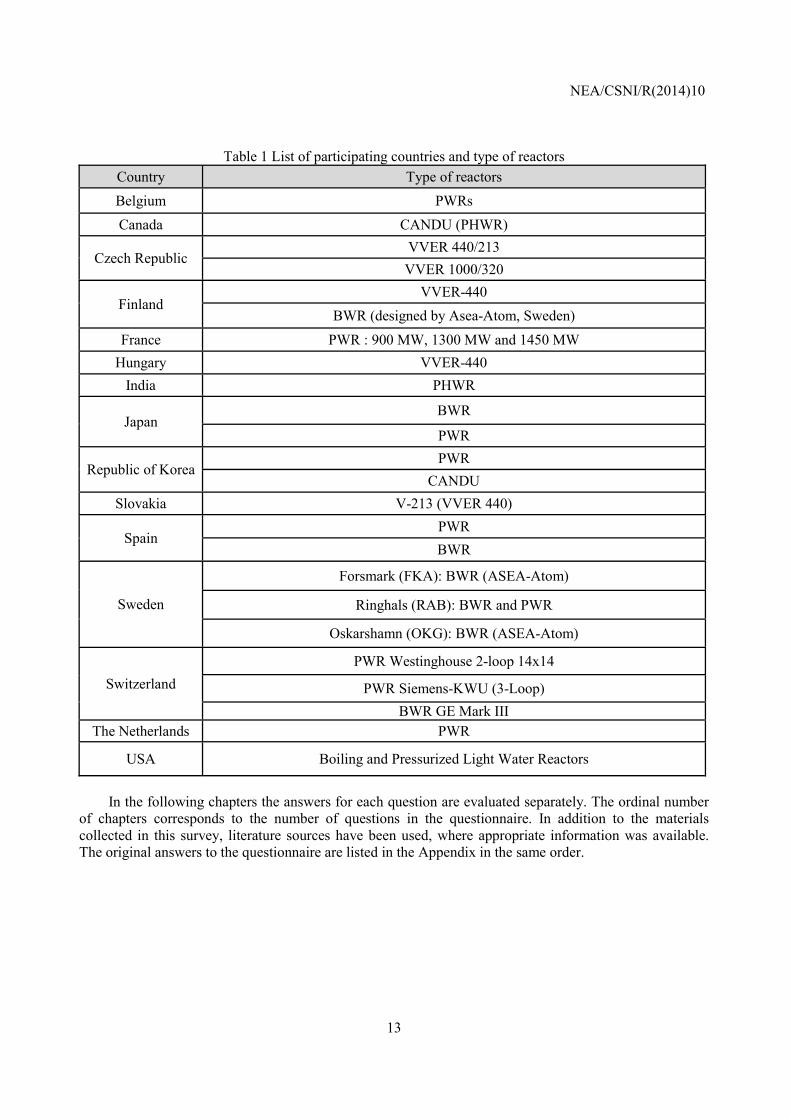
Table 1 List of participating countries and type of reactors
Country Type of reactors Belgium PWRs Canada CANDU (PHWR)
Czech Republic VVER 440/213 VVER 1000/320
Finland VVER-440
BWR (designed by Asea-Atom, Sweden)
France PWR : 900 MW, 1300 MW and 1450 MW Hungary VVER-440
India PHWR
Japan BWR
PWR
Republic of Korea PWR
CANDU Slovakia V-213 (VVER 440)
Spain PWR BWR
Sweden
Forsmark (FKA): BWR (ASEA-Atom)
Ringhals (RAB): BWR and PWR
Oskarshamn (OKG): BWR (ASEA-Atom)
Switzerland PWR Westinghouse 2-loop 14x14
PWR Siemens-KWU (3-Loop) BWR GE Mark III
The Netherlands PWR
USA Boiling and Pressurized Light Water Reactors
In the following chapters the answers for each question are evaluated separately. The ordinal number
of chapters corresponds to the number of questions in the questionnaire. In addition to the materials collected in this survey, literature sources have been used, where appropriate information was available. The original answers to the questionnaire are listed in the Appendix in the same order.

NEA/CSNI/R(2014)10
14
NEA/CSNI/R(2014)10
15
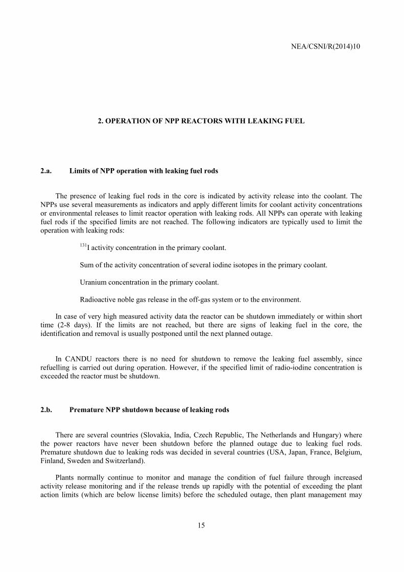
2. OPERATION OF NPP REACTORS WITH LEAKING FUEL
2.a. Limits of NPP operation with leaking fuel rods
The presence of leaking fuel rods in the core is indicated by activity release into the coolant. The
NPPs use several measurements as indicators and apply different limits for coolant activity concentrations or environmental releases to limit reactor operation with leaking rods. All NPPs can operate with leaking fuel rods if the specified limits are not reached. The following indicators are typically used to limit the operation with leaking rods:
• 131I activity concentration in the primary coolant.
• Sum of the activity concentration of several iodine isotopes in the primary coolant.
• Uranium concentration in the primary coolant.
• Radioactive noble gas release in the off-gas system or to the environment.
In case of very high measured activity data the reactor can be shutdown immediately or within short time (2-8 days). If the limits are not reached, but there are signs of leaking fuel in the core, the identification and removal is usually postponed until the next planned outage.
In CANDU reactors there is no need for shutdown to remove the leaking fuel assembly, since
refuelling is carried out during operation. However, if the specified limit of radio-iodine concentration is exceeded the reactor must be shutdown.
2.b. Premature NPP shutdown because of leaking rods
There are several countries (Slovakia, India, Czech Republic, The Netherlands and Hungary) where
the power reactors have never been shutdown before the planned outage due to leaking fuel rods. Premature shutdown due to leaking rods was decided in several countries (USA, Japan, France, Belgium, Finland, Sweden and Switzerland).
Plants normally continue to monitor and manage the condition of fuel failure through increased activity release monitoring and if the release trends up rapidly with the potential of exceeding the plant action limits (which are below license limits) before the scheduled outage, then plant management may
NEA/CSNI/R(2014)10
16
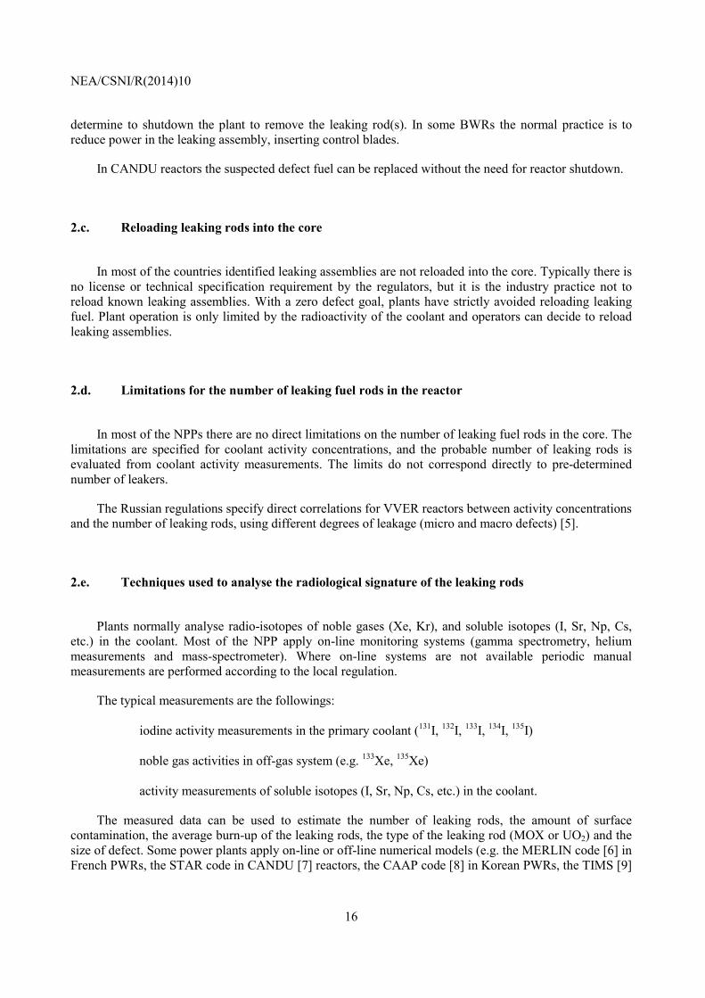
determine to shutdown the plant to remove the leaking rod(s). In some BWRs the normal practice is to reduce power in the leaking assembly, inserting control blades.
In CANDU reactors the suspected defect fuel can be replaced without the need for reactor shutdown.
2.c. Reloading leaking rods into the core
In most of the countries identified leaking assemblies are not reloaded into the core. Typically there is
no license or technical specification requirement by the regulators, but it is the industry practice not to reload known leaking assemblies. With a zero defect goal, plants have strictly avoided reloading leaking fuel. Plant operation is only limited by the radioactivity of the coolant and operators can decide to reload leaking assemblies.
2.d. Limitations for the number of leaking fuel rods in the reactor
In most of the NPPs there are no direct limitations on the number of leaking fuel rods in the core. The
limitations are specified for coolant activity concentrations, and the probable number of leaking rods is evaluated from coolant activity measurements. The limits do not correspond directly to pre-determined number of leakers.
The Russian regulations specify direct correlations for VVER reactors between activity concentrations and the number of leaking rods, using different degrees of leakage (micro and macro defects) [5].
2.e. Techniques used to analyse the radiological signature of the leaking rods
Plants normally analyse radio-isotopes of noble gases (Xe, Kr), and soluble isotopes (I, Sr, Np, Cs,
etc.) in the coolant. Most of the NPP apply on-line monitoring systems (gamma spectrometry, helium measurements and mass-spectrometer). Where on-line systems are not available periodic manual measurements are performed according to the local regulation.
The typical measurements are the followings:
• iodine activity measurements in the primary coolant (131I, 132I, 133I, 134I, 135I)
• noble gas activities in off-gas system (e.g. 133Xe, 135Xe)
• activity measurements of soluble isotopes (I, Sr, Np, Cs, etc.) in the coolant.
The measured data can be used to estimate the number of leaking rods, the amount of surface contamination, the average burn-up of the leaking rods, the type of the leaking rod (MOX or UO2) and the size of defect. Some power plants apply on-line or off-line numerical models (e.g. the MERLIN code [6] in French PWRs, the STAR code in CANDU [7] reactors, the CAAP code [8] in Korean PWRs, the TIMS [9]
NEA/CSNI/R(2014)10
17
and RTOP-CA codes [10] in Russian VVER reactors, the PEPA code [11] in Czech Republic and the RING code [12] in Hungary) for the evaluation of measured activity concentrations.
2.f. Limitations for the maximum coolant activity concentrations
Limitations exist for fission product, activation products and corrosion product concentrations in the
primary coolant and on the mass of tramp uranium in the core. Several power plants monitor the fuel reliability index, which is a normalised value calculated from coolant activity data considering linear power and water purification rates. The most common limitation depends on 131I or equivalent iodine activities. The activity concentration limits are often tied to water purification rates. The maximum allowable iodine activity concentration in the coolant is in the range of 106–108 Bq/kg, the noble gases concentration limits are somewhat higher. These values are typically much higher than the activity concentrations that can be caused by one leaking fuel rod in the reactor.
The tramp uranium mass limits in the primary cooling circuit are between 0.2–100 grams in the primary circuit. Lower limits are also specified in most of the power plants to apply some actions in order to reduce coolant activity without immediate shutdown. The actual values are specific not only for reactor types but for each plant. For example in Sweden 100 grams uranium is a high upper limit at Oskarshamn NPPs, resulting in immediate shutdown and in a special investigation about the root cause and the need of corrective actions before start-up of the plant. Planning for an extra outage within a few weeks starts as soon as there are indications on uranium release (based on Np activity level in the primary coolant). This means that an extra outage will take place and limit the tramp U addition to a much lower level in order to mitigate too much contamination of the internal parts and primary system.
In case of CANDU reactors the leaking fuel can be discharged during operation, for this reason there is no need to shutdown the reactor in order to remove defect fuel. The high 131I activity concentration, however, may in principle result in shutdown for CANDUs, too. In CANDU reactors a combination of gaseous fission product detectors, grab-sampling in the lab, and delayed-neutron detectors is used. In addition, the suspected fuel channels will be defueled and iodine-spikes will be monitored.
In the USA all nuclear power plants have a Failed Fuel Action Plan, which identifies specific actions to be taken based on activity releases. Similar action plans exist in other countries as well.
In several PWR and VVER power plants, the power variation may be limited when leaking fuel is in the core.
Some BWR plants implement flux tilting and power suppression, when leaking rods are present.
In the Czech Republic the ratio of activity iodine concentrations is used to change operational conditions of VVER-1000 reactor: if 131I/133I ratio is in the range of 0.2–0.5 power ramp modifications are applied, while in case of 0.6–2.0 ratio the load follower manoeuvres are stopped and the coolant activity sampling frequency is increased.
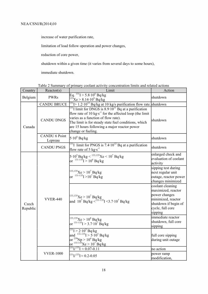
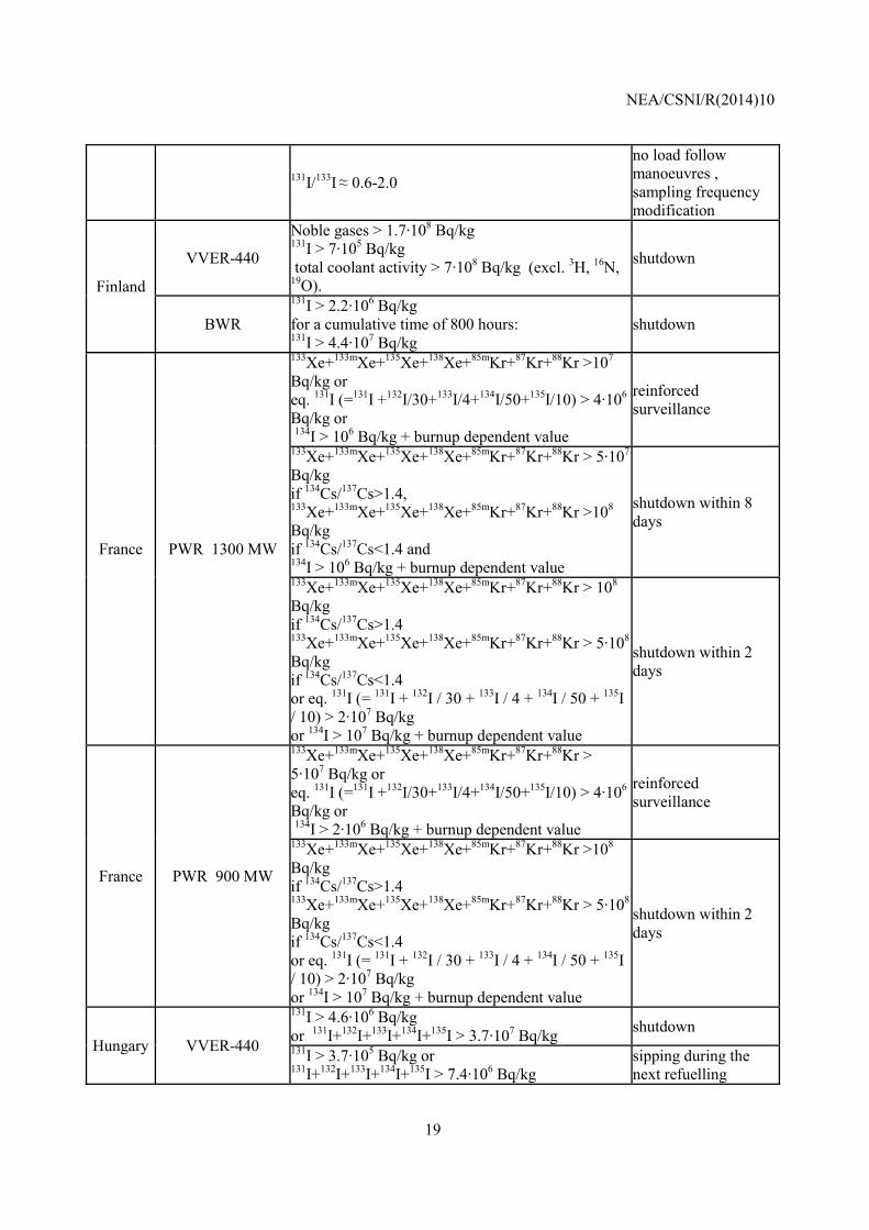
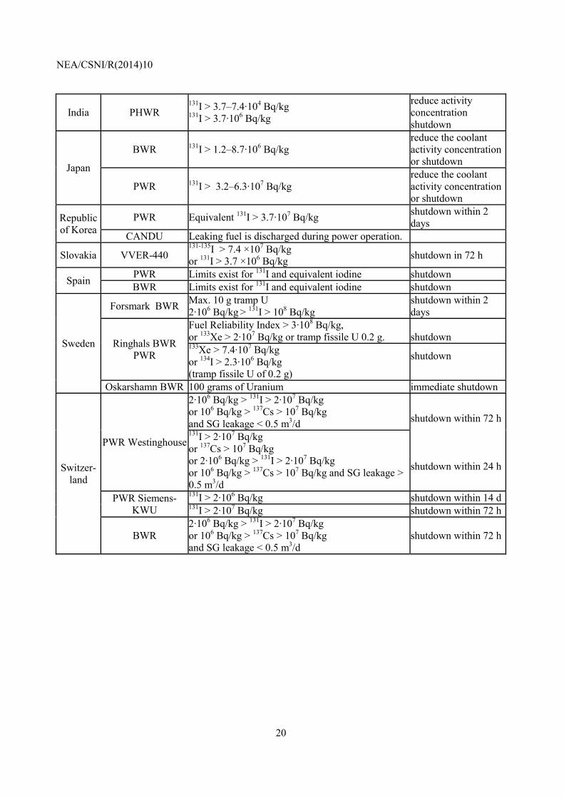
The typical actions in BWR, PWR and VVER reactors with high coolant activity concentrations are the followings (Table 2):
• reinforced surveillance, increase of coolant sampling frequency,
• sipping test during next regular unit outage,
NEA/CSNI/R(2014)10
18
• increase of water purification rate,
• limitation of load follow operation and power changes,
• reduction of core power,
• shutdown within a given time (it varies from several days to some hours),
• immediate shutdown.
Table 2 Summary of primary coolant activity concentration limits and related actions
Country Reactor(s) Limit Action
Belgium PWRs Eq. 131I > 5.8·106 Bq/kg 133Xe > 8.14·109 Bq/kg shutdown
Canada
CANDU BRUCE 131I> 1.2·1012 Bq/kg at 10 kg/s purification flow rate. shutdown
CANDU DNGS
131I limit for DNGS is 8.9·1011 Bq at a purification flow rate of 10 kg·s-1 for the affected loop (the limit varies as a function of flow rate). The limit is for steady state fuel conditions, which are 15 hours following a major reactor power change or fueling.
shutdown
CANDU 6 Point Lepreau 5·108 Bq/kg shutdown
CANDU PNGS 131I limit for PNGS is 7.4·1012 Bq at a purification flow rate of 5 kg·s-1 shutdown
Czech Republic
VVER-440
5·105 Bq/kg < 133,135Xe < 107 Bq/kg or 131-135I > 106 Bq/kg
enlarged check and evaluation of coolant activity
133,135Xe > 107 Bq/kg or 131-135I >107 Bq/kg
sipping test during next regular unit outage, reactor power changes minimized
133,135Xe > 107 Bq/kg and 107 Bq/kg <131-135I <3.7·107 Bq/kg
coolant cleaning maximized, reactor power changes minimized, reactor shutdown if begin of cycle, full core sipping
133,135Xe > 108 Bq/kg or 131-135I > 3.7·107 Bq/kg
immediate reactor shutdown, full core sipping
131I > 2·105 Bq/kg and 131-135I > 5·105 Bq/kg or 239Np > 104 Bq/kg or 133-135Xe > 107 Bq/kg
full core sipping during unit outage
VVER-1000
131I/133I ≈ 0.07-0.11 no action 131I/133I ≈ 0.2-0.05 power ramp
modification,
NEA/CSNI/R(2014)10
19
131I/133I ≈ 0.6-2.0
no load follow manoeuvres , sampling frequency modification
Finland
VVER-440
Noble gases > 1.7·108 Bq/kg 131I > 7·105 Bq/kg total coolant activity > 7·108 Bq/kg (excl. 3H, 16N, 19O).
shutdown
BWR 131I > 2.2·106 Bq/kg for a cumulative time of 800 hours: 131I > 4.4·107 Bq/kg
shutdown
France PWR 1300 MW
133Xe+133mXe+135Xe+138Xe+85mKr+87Kr+88Kr >107 Bq/kg or eq. 131I (=131I +132I/30+133I/4+134I/50+135I/10) > 4·106 Bq/kg or 134I > 106 Bq/kg + burnup dependent value
reinforced surveillance
133Xe+133mXe+135Xe+138Xe+85mKr+87Kr+88Kr > 5·107 Bq/kg if 134Cs/137Cs>1.4, 133Xe+133mXe+135Xe+138Xe+85mKr+87Kr+88Kr >108 Bq/kg if 134Cs/137Cs<1.4 and 134I > 106 Bq/kg + burnup dependent value
shutdown within 8 days
133Xe+133mXe+135Xe+138Xe+85mKr+87Kr+88Kr > 108 Bq/kg if 134Cs/137Cs>1.4 133Xe+133mXe+135Xe+138Xe+85mKr+87Kr+88Kr > 5·108 Bq/kg if 134Cs/137Cs<1.4 or eq. 131I (= 131I + 132I / 30 + 133I / 4 + 134I / 50 + 135I / 10) > 2·107 Bq/kg or 134I > 107 Bq/kg + burnup dependent value
shutdown within 2 days
France PWR 900 MW
133Xe+133mXe+135Xe+138Xe+85mKr+87Kr+88Kr > 5·107 Bq/kg or eq. 131I (=131I +132I/30+133I/4+134I/50+135I/10) > 4·106 Bq/kg or 134I > 2·106 Bq/kg + burnup dependent value
reinforced surveillance
133Xe+133mXe+135Xe+138Xe+85mKr+87Kr+88Kr >108 Bq/kg if 134Cs/137Cs>1.4 133Xe+133mXe+135Xe+138Xe+85mKr+87Kr+88Kr > 5·108 Bq/kg if 134Cs/137Cs<1.4 or eq. 131I (= 131I + 132I / 30 + 133I / 4 + 134I / 50 + 135I / 10) > 2·107 Bq/kg or 134I > 107 Bq/kg + burnup dependent value
shutdown within 2 days
Hungary VVER-440
131I > 4.6·106 Bq/kg or 131I+132I+133I+134I+135I > 3.7·107 Bq/kg shutdown 131I > 3.7·105 Bq/kg or 131I+132I+133I+134I+135I > 7.4·106 Bq/kg
sipping during the next refuelling
NEA/CSNI/R(2014)10
20
India PHWR 131I > 3.7–7.4·104 Bq/kg
131I > 3.7·106 Bq/kg
reduce activity concentration shutdown
Japan
BWR 131I > 1.2–8.7·106 Bq/kg reduce the coolant activity concentration or shutdown
PWR 131I > 3.2–6.3·107 Bq/kg reduce the coolant activity concentration or shutdown
Republic of Korea
PWR Equivalent 131I > 3.7·107 Bq/kg shutdown within 2 days
CANDU Leaking fuel is discharged during power operation.
Slovakia VVER-440 131-135I > 7.4 ×10⁷ Bq/kg or 131I > 3.7 ×10⁶ Bq/kg shutdown in 72 h
Spain PWR Limits exist for 131I and equivalent iodine shutdown BWR Limits exist for 131I and equivalent iodine shutdown
Sweden
Forsmark BWR Max. 10 g tramp U 2·106 Bq/kg > 131I > 108 Bq/kg
shutdown within 2 days
Ringhals BWR PWR
Fuel Reliability Index > 3·108 Bq/kg, or 133Xe > 2·107 Bq/kg or tramp fissile U 0.2 g.
shutdown
133Xe > 7.4·107 Bq/kg or 134I > 2.3·106 Bq/kg (tramp fissile U of 0.2 g)
shutdown
Oskarshamn BWR 100 grams of Uranium immediate shutdown
Switzer-land
PWR Westinghouse
2·106 Bq/kg > 131I > 2·107 Bq/kg or 106 Bq/kg > 137Cs > 107 Bq/kg and SG leakage < 0.5 m3/d shutdown within 72 h
shutdown within 24 h
131I > 2·107 Bq/kg or 137Cs > 107 Bq/kg or 2·106 Bq/kg > 131I > 2·107 Bq/kg or 106 Bq/kg > 137Cs > 107 Bq/kg and SG leakage > 0.5 m3/d
PWR Siemens-KWU
131I > 2·106 Bq/kg shutdown within 14 d131I > 2·107 Bq/kg shutdown within 72 h
BWR 2·106 Bq/kg > 131I > 2·107 Bq/kg or 106 Bq/kg > 137Cs > 107 Bq/kg and SG leakage < 0.5 m3/d
shutdown within 72 h
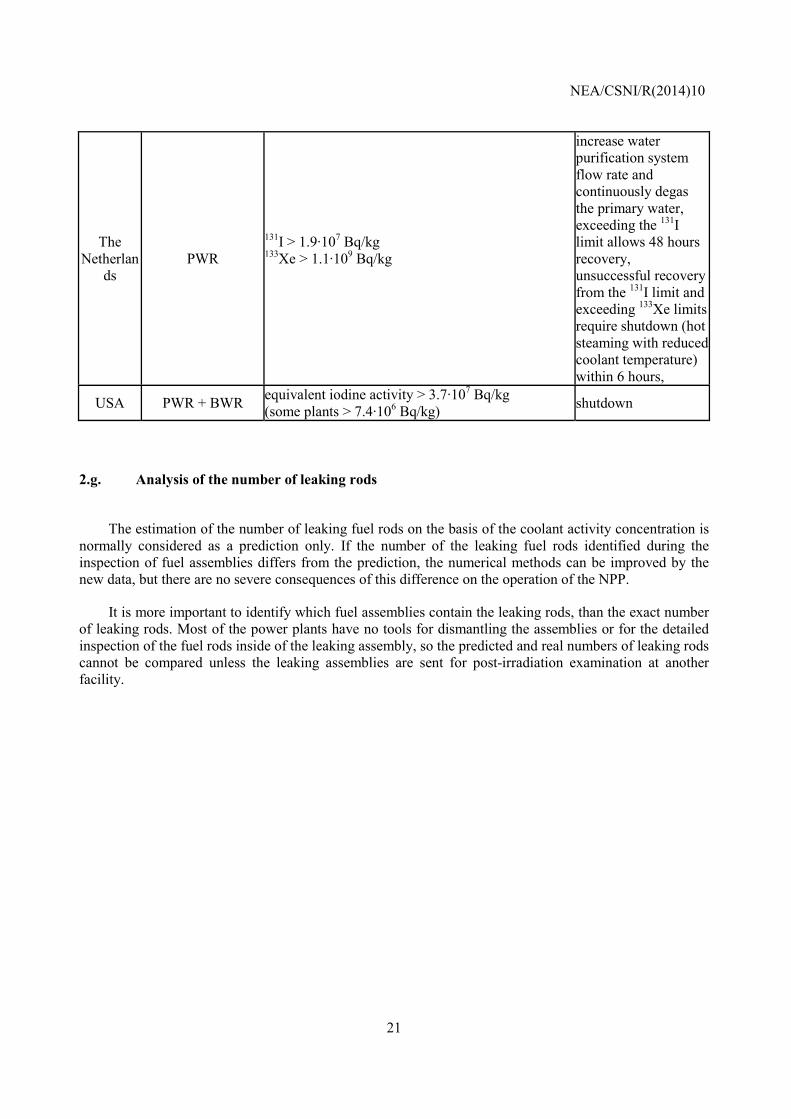
NEA/CSNI/R(2014)10
21
The Netherlan
ds PWR
131I > 1.9·107 Bq/kg 133Xe > 1.1·109 Bq/kg
increase water purification system flow rate and continuously degas the primary water, exceeding the 131I limit allows 48 hours recovery, unsuccessful recovery from the 131I limit and exceeding 133Xe limits require shutdown (hot steaming with reduced coolant temperature) within 6 hours,
USA PWR + BWR equivalent iodine activity > 3.7·107 Bq/kg (some plants > 7.4·106 Bq/kg) shutdown
2.g. Analysis of the number of leaking rods
The estimation of the number of leaking fuel rods on the basis of the coolant activity concentration is
normally considered as a prediction only. If the number of the leaking fuel rods identified during the inspection of fuel assemblies differs from the prediction, the numerical methods can be improved by the new data, but there are no severe consequences of this difference on the operation of the NPP.
It is more important to identify which fuel assemblies contain the leaking rods, than the exact number of leaking rods. Most of the power plants have no tools for dismantling the assemblies or for the detailed inspection of the fuel rods inside of the leaking assembly, so the predicted and real numbers of leaking rods cannot be compared unless the leaking assemblies are sent for post-irradiation examination at another facility.

NEA/CSNI/R(2014)10
22
NEA/CSNI/R(2014)10
23
3. IDENTIFICATION OF LEAKING FUEL ASSEMBLIES AND FUEL RODS
3.a. Identification of the leaking assembly after shutdown
The identification of leaking fuel assemblies after shutdown usually is carried out with testing the
assemblies under transient conditions (e.g. change of vertical position or heating up of the assembly). During these transients increased activity release from the leaking rods can be detected. Different sipping methods can be applied (e.g. in-core sipping, telescope sipping, canister sipping) in the reactor vessel, in the spent fuel pool or during removal from the core with the refuelling machine.
Sometimes (e.g., with damaged peripheral rods) the visual inspection can identify the leaking assembly. In some BWR reactors the leaking assemblies can be identified before shutdown.
For CANDU, with the on-line monitoring of delayed neutron emitting fission products (137I and 87Br) in the coolant, a leaking fuel bundle can be identified by bundle discharges in the leaking channel [1]. In Canadian reactors a combination of in-core detection and in-bay inspection techniques are used. Coolant activity is monitored during and after suspected defect bundles are discharged to confirm that the defect bundle has been removed from the core. Suspect bundles are then sent to the inspection table. Inspection of fuel bundles is performed via remote camera in the irradiated fuel bay. Particularly in the case of “defect excursions” (several bundles from a particular reactor unit or manufacturer experiencing leaks in a short time period), some leaking fuel bundles are sent for post-irradiation examination to determine the cause of the leak.
Some power plants have no tools for the identification of leaking fuel assemblies.
NEA/CSNI/R(2014)10
24
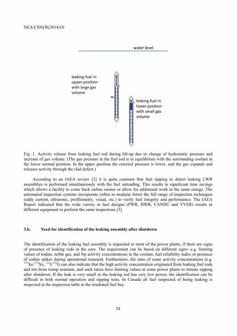
Fig. 1. Activity release from leaking fuel rod during lift-up due to change of hydrostatic pressure and increase of gas volume. (The gas pressure in the fuel rod is in equilibrium with the surrounding coolant in the lower normal position. In the upper position the external pressure is lower, and the gas expands and releases activity through the clad defect.)
According to an IAEA review [3] it is quite common that fuel sipping to detect leaking LWR assemblies is performed simultaneously with the fuel unloading. This results in significant time savings which allows a facility to come back online sooner or allow for additional work in the same outage. The automated inspection systems incorporate (often in modular form) the full range of inspection techniques (eddy current, ultrasonic, profilometry, visual, etc.) to verify fuel integrity and performance. The IAEA Report indicated that the wide variety in fuel designs (PWR, BWR, CANDU and VVER) results in different equipment to perform the same inspections [3].
3.b. Need for identification of the leaking assembly after shutdown
The identification of the leaking fuel assembly is requested in most of the power plants, if there are signs of presence of leaking rods in the core. The requirement can be based on different signs: e.g. limiting values of iodine, noble gas, and Np activity concentrations in the coolant, fuel reliability index or presence of iodine spikes during operational transient. Furthermore, the ratio of some activity concentrations (e.g. 133Xe/135Xe, 131I/133I) can also indicate that the high activity concentration originated from leaking fuel rods and not from tramp uranium, and such ratios have limiting values at some power plants to initiate sipping after shutdown. If the leak is very small or the leaking rod has very low power, the identification can be difficult in both normal operation and sipping tests. In Canada all fuel suspected of being leaking is inspected at the inspection table in the irradiated fuel bay.
NEA/CSNI/R(2014)10
25
3.c. Identification of the root cause of fuel failure
In most of the countries there is a strong intention to identify root cause of fuel failures in order to
avoid similar failures in the future. The examination usually can be carried out by pool inspections. Sometimes the need for examination in special hot cell facilities may arise, which are not available at the power plants.
In the US, it is normal industry practice to identify the root cause to the extent possible.
In Japan, the visual inspection and the fibre scope investigation will be performed on the fuel assembly in which a leakage was detected by the shipping inspection, PIEs will be performed in case of a comparatively large scale or a special type of failure.
In France, it is required to investigate the failure root cause. Nevertheless, if a generic failure root cause has been identified and if there is no, or little, doubt on the origin of the leak, only a limited number of leaking rods is examined.
According to the Swedish experience, the root cause can typically be determined by careful visual inspection and other pool-side inspection methods, but in some cases, typically some fabrication defects, it can only be done by hot cell PIE.
In Canada, visual inspection is performed at the inspection table in the irradiated fuel bay. In the case of “defect excursions”, post-irradiation examinations are carried out at Chalk River Laboratories to determine the cause of the leak. The fuel bundle or rod is initially examined by optical microscope in a hot cell. The path for further examination is determined by the examination results and consultations with the utility.
3.d. Identification of leaking fuel rods
The identification of leaking fuel rods in the assembly can be performed by non-destructive methods:
visual inspection, eddy current and ultrasonic testing. Some fuel assembly types cannot be dismantled, so the individual leaking rods cannot be identified at the NPP. In such cases the examination can be done only in special hot cells after cutting the assembly. In hot cells, optical inspection can be done by microscope, and helium leak testing can be done to confirm or look for small defects.
3.e. Replacement of leaking rods
In case of large fuel assemblies the leaking rod normally can be removed and replaced by a similar
rod or a dummy rod and the repaired assembly can then be used again in the reactor. It depends on the degree of degradation of the fuel and on its burn-up. Leaking rods in high burn-up fuel assemblies will not be changed due to economic reasons. If the leaking fuel rods cannot be removed (e.g. due to assembly design or lack of tools at the NPP), the replacement is not an option.
In the US, the primary criteria for replacement are the residual energy of the remaining assembly, available time to do the replacement, and the likelihood of additional failures. Many utilities choose to
NEA/CSNI/R(2014)10
26
replace leaking fuel with previously discharged fuel assemblies from the spent fuel pool rather than replacing individual rods due to refuelling outage critical path considerations.
In Japan only fuel vendors are permitted to make repairs t o fuel assemblies: operators are not allowed to replace fuel rods in an assembly. Therefore replacement of leaking rods practically is not performed in any plants.
In CANDU reactors, leaking rods cannot be replaced because of the bundle design (rods are welded to bundle end-plates), and the low bundle cost means that there is no economic incentive to replace individual rods. Bundles with leaking fuel rods (similarly to other normal bundles) are not reloaded into the reactor.
3.f. Repair of the leaking fuel assembly
There are several countries where the fuel assemblies cannot be repaired at the NPP (Japan, Slovakia,
India, Hungary and Canada). In other countries tools to replace leaking fuel rods are available at the site for some fuel designs. However, the fuel replacement typically is not performed by the staff of the NPP, but the plant operator relies upon the fuel vendor to bring equipment to the site to repair leaking fuel assemblies. The decision to remove a leaking rod should be based on the potential risk to lose the rod integrity during the withdrawal phase (e.g. complete rod break and fuel fragment dispersal due to secondary hydriding).
In some countries back-end handling of fuel assemblies containing leaking fuel rods might be difficult. It is much easier to handle the repaired fuel assemblies in the normal manner and treat the leaking rods separately.
Germany [4] considers damaged grid spacers, spacer springs, vanes on grid spacers and tie-plates to be replaceable parts. This is a viable solution when the damaged part jeopardizes the stability of the assembly, such as its ability to maintain configuration for criticality control or continue to be retrievable by normal means.
3.g. Criterion on the replacement of leaking rods (UO2 or dummy rods)
There is no special criterion on the replacement of leaking rods by fuel or dummy rods. However,
different practices exist in different countries:
• In Switzerland the type of rod to be used for replacement depends on the status of the spacer (intact or damage), burn-up (neutronic considerations) and availability of a suitable UO2 rod.
• In the US the replacement rod is usually a dummy rod (solid stainless steel) or a used rod. The type of rod and the number of rods that can be replaced in each assembly may be dependent upon Technical Specifications or other operational limits.
• In Spain normally dummy rods are used, but in some instances UO2 rods are applied for replacement, too.
• In the Czech Republic dummy rods are used for replacement.
NEA/CSNI/R(2014)10
27
• In Sweden only dummy or UO2 rods are allowed. Before using UO2 rods new reactor physics calculations are needed.
• In the Netherlands a Zr dummy rod is always used to replace a defective rod.
• In Finland the choice between dummy and UO2 rods is based on burn-up of the assembly and the imposed reactor-physical penalty for operation.
• In the Republic of Korea, when small number of rods is leaking, stainless steel dummy rods are used (PWR).
• For small fuel assemblies (e.g. CANDU or VVER-440) the replacement is not considered.

NEA/CSNI/R(2014)10
28
NEA/CSNI/R(2014)10
29
4. CONSIDERATION OF LEAKING FUEL IN POSTULATED ACCIDENTS
4.a. Consideration of activity release from leaking fuel rods in accidents
In most of the countries activity releases due to leaking fuel and iodine spike are considered for
radiological consequences evaluation in case of DBA analysis. Most common accidents (adopted for radiological consequences evaluation) are steam generator tube rupture (in PWR and PHWR design), pump seal failures (in PHWR design) and main steam line break (both in PWR and BWR design), namely those accidents during which containment bypass potentially occur (although it depends very much on postulated event and related boundary conditions). In Canada the release from leaking fuel is also taken into account in case of refuelling machine accidents, some secondary side accidents and design basis earthquake incidents.
There are countries in which activities coming from leaking fuel are not considered. In the safety analyses they normally consider a given number of leaking fuel rods, even if no fuel failure takes place in the accident. Typically, the gap inventory of 1% of all fuel rods is considered in many types of analyses.
In case of LOCA and RIA accidents the effect of leaking fuel rods is small compared to activities coming from the fuel failed during the accident, so the spiking effect can be neglected.
4.b. Number of leaking fuel rods considered in the accident analyses
The consideration of leaking fuel and more specifically the number of leaking rods can be grouped
into three categories:
• Assumption on number of leaking rods, typical value ranges 1–2% of the total fuel rods.
• No assumption on number of leaking rods, rather assumption on coolant activity. Typically in this case the maximum allowed coolant activity (coming from Technical Specification) is considered in the analysis.
• Consideration of failed rods caused by the analysed accident, i.e., not prior present (up to 100% in case of LBLOCA in PWR).
4.c. Calculation of spiking effect
From item 4.a. it is evident that some countries do not take into account the spiking effect. Rather,
when spiking effect is considered different approaches are followed:
• multiplication factors prescribed by regulator (e.g. ENSI);
NEA/CSNI/R(2014)10
30
• arbitrary increase of coolant activity;
• considered in calculation of equivalent 131I;
• adopting correlation in the release rate and considering equilibrium condition at accident start;
• multiplication factor of the release rate associated with normal operation conditions; released activity due to spiking specifically set depending upon radioisotope.
4.d. Influence from leaking fuel during a LOCA
Regarding the consideration of leaking fuel in LOCA analyses, the following apply for different
countries. In most of the cases up to 100% of fuel rods failure is assumed in case of LOCA for radiological impact evaluation. In less conservative calculation failure of all rods is not assumed. Prediction of burst and/or ballooned fuel rods, caused by the postulated accident, is performed and their inventory is considered within the radiological impact evaluation. Burst and/or ballooned fuel rods contribution to the dose evaluation is again much higher than that pertaining to the leaking fuel. Definitely, in this case, the leaking fuel contribution is negligible.
4.e. Regulatory criteria on leaking fuel in LOCA
There are no specific criteria to address the leaking fuel issue in case of LOCA (this is especially true
in those countries in which failure of all rods is assumed). The Netherland regulatory guides (following specification of German guide) impose a leaking fuel fraction of 10% of the core (or less if demonstrated) in case of LBLOCA.
4.f. Change of safety margin for the core with leaking fuel(s) at LOCA
Safety margins are not changed in case of presence of leaking fuel, because of conservative
assumptions made for radiological consequence evaluation in case of LOCA.
4.g. Criteria for leaking fuel during LOCA quenching
No specific criterion/limit is assumed for quenching of leaking fuel. The same criteria are applied for
intact and leaking fuel rods in terms of maximum allowed fuel rod cladding temperature, maximum allowed degree of oxidation, coolability, and hydrogen uptake.
NEA/CSNI/R(2014)10
31
4.h. Experimental data on behaviour of a leaking fuel during LOCA quench
There is an evident lack of experimental data specifically addressing the behaviour of leaking rods
during quench phase after a LOCA. A more brittle response is expected due to possible secondary hydriding in case of water ingress in flawed rods. However, ballooning and burst will not take place with a leaking fuel rod, so secondary hydriding during a LOCA event is not expected. In case of very long oxidation times, an intact fuel rod that has ballooned and ruptured during the transient can become even more brittle than a leaker .
Some experiments have been conducted at the PBF facility with leaking fuel under power-cooling-mismatch conditions (see chapter 12.a).
There has been work in Canada on defective fuel behaviour at power ranging from 25-60 kW/m. In addition, defective fuel quenching studies have been carried out.
4.i. Effect of secondary hydriding on cladding ductility
Secondary hydriding may occur in two ways with Zr cladding:
• during normal operation heavy hydride formation can take place due to water penetration into the rod through the primary leak (usually in the upper section of the fuel rod)
• during accidents, after ballooning and burst steam, can enter the internal volume of the rod, in which case intense oxidation takes place and the produced hydrogen will be absorbed by the metallic Zr in the vicinity of the ballooned section.
Obviously the second mechanism cannot happen with the leaking fuel rod, since the leaking rod will not balloon. It means that the weakest section (ballooning with thin wall) of the normal fuel rod will not be formed during a LOCA event with a leaking rod.
The first mechanism can lead to hydrogen accumulation in the upper gas volume of the fuel rod. The uptake of hydrogen by Zr cladding results in brittle hydrided structure and it can cause secondary failures during transient, accidents or even normal operation.
Consideration of specific limit for leaking fuel seems to be not needed because of two opposite reasons/assumptions, in case of LOCA analysis:
• If the failure of all rods is assumed, the leaking fuel limit is useless.
• If a less conservative assumption is adopted, the number of tolerated leakers during normal operation must be very low so that core coolability in case of LOCA is not challenged, even though poorer mechanical properties have to be expected for leaking fuel
Definitely, the effect of normal operational clad hydriding on the mechanical load bearing capabilities of the leaking fuel is not considered in the current regulation.
NEA/CSNI/R(2014)10
32
4.j. Core coolability for leaking fuels during LOCA
Due to the limited number of permitted leaking fuel rods, core coolability during LOCA is not
expected to be challenged.
4.k. Fall out of fuel pellets/fragments from leaking fuel rods during LOCA
The potential fall out of pellets or fragmentation of leaking fuel is basically not considered in the
frame of core coolability. It should be considered also that the risk of fuel pellet dispersal is lower for pre-transient leaking rods than for regular fuel rods because they don’t undergo cladding expansion during the heat-up phase of the LOCA transient (no pressure-driven loading onto the cladding). However, if the leaking rod is heavily hydrided, the fragmentation of cladding can happen due to transient loads and it can open a path for the fall out of fuel fragments.
4.l. Change of safety margin for the core with leaking fuel at an RIA
In general safety limits are not changed even in case of the presence of leaking fuel, although it is
recognized that leaking fuel has lower capability in withstanding a RIA and consequently a higher probability to cause fuel coolant interaction. Justification to keep the safety limits unchanged is basically due to the low number of leaking fuel rods and the very low probability that localized power increase (e.g. due to rod ejection in a PWR) occurs in the same core region where a leaking rod is present.
It should be noted that in Japan, different threshold for rod rupture is to be applied to leaking fuel. The threshold and consequences of rod rupture are direct outcomes of RIA experiments with waterlogged fresh fuel rods in NSRR test reactor.
4.m. Regulatory criteria on leaking fuel in RIA
As safety margins are not changed in case of leaking fuel, also current regulatory criteria do not
account for the leaking rods. This is generally true, however it should be noted that reconsideration of RIA limits is in progress in many countries.
Japan is an example on how leaking fuel is being considered. Namely, the rod rupture limit is reduced, and fuel rods beyond the limit are treated as ruptured. A certain existing ratio of leaking rods is to be assumed (Japanese guidelines suggests 1% of all the fuel rods in the core).
NEA/CSNI/R(2014)10
33
4.n. Influence of leaking fuel at RIA
There are no specific aspects related with leaking fuel to be considered in reactor safety evaluation.
Basically conservative assumptions are applied to bound the possible presence of leaking rods (this is especially true when radiological consequences are evaluated), although it is recognized that flawed clad has worse mechanical properties than intact clad.
It should be noted that in Japan different safety limits are to be considered for leaking fuel. The threshold and consequences of rod rupture are direct outcomes of RIA experiments with waterlogged fresh fuel rods in NSRR test reactor.

NEA/CSNI/R(2014)10
34
NEA/CSNI/R(2014)10
35
5. STORAGE OF LEAKING FUEL IN THE SPENT FUEL POOL (SFP)
5.a. Common storage of leaking and intact assemblies in the SFP
At most of the NPPs the leaking fuel assemblies are stored together with the intact assemblies in the
SFP. If the assemblies are severely damaged, special casks are used. In Korean PWRs, special cells are available in the pool for leaking assemblies. In case of CANDU reactors, the leaking fuels are stored on the inspection side of the bay separately in trays.
After the removal of the leaking rods – if it is feasible with the given fuel design – the rods are stored separately and the repaired assembly does not release any additional activity to the pool.
Some special procedures have been developed to deal with leaking fuel stored in water pools in the 1970s in the US, including both fabrication of underwater hoods intended to collect radioactive gases if fuel were to leak in the pool, and special canisters to isolate leaking fuel from pool water. In some instances these procedures proved to be useful. However, the vast majority of leaking fuel does not require special handling and is stored in the same manner as intact fuel [13].
5.b. Containers for the storage of leaking spent fuel assemblies
Many power plants have special containers (canisters, casks) for the storage of leaking fuel rod or fuel
assemblies. If the leaking fuel rod can be removed, then the rods are stored in the containers. If it cannot be done, the whole severely damaged assemblies are placed there (e.g. if there is a risk of fall out of fuel fragments from the rod, extensive cladding damage, degraded handling conditions). In Slovakia the placement of an assembly into the closed container can be decided on the basis of caesium activity concentration increase in the storage pool.
In CANDU, leak-suspected fuel bundles are canned and separately stored from the stored intact fuel bundles in the spent fuel pool (called spent fuel bay in CANDU). For hot cell examinations, leaking fuel elements can be shipped, after being taken out from the leak-suspected fuel bundle. The whole leak-suspected bundle can also be shipped for hot cell examinations.
There were “coffins” provided during commissioning days which allowed for sampling of activity on a periodic basis in Canada. Experience over the years with defects did not warrant any special handling – they were scrapped. Broken fuel bundles are stored on normal trays in the primary bay inspection side.
In Russia special containers have been developed for the transport for leaking RBMK fuel assemblies. Air tight ampoules of original design ensure safe transportation and interim storage of spent fuel assemblies containing leaking fuel rods [14].
Regulations in Germany require fuel that has cladding breaches developed in-reactor to be segregated and placed in sealed containers for wet storage. Rods with any sort of cladding breach cannot be put in dry storage and are currently left in the pool in these containers [4].
NEA/CSNI/R(2014)10
36
In the USA, regulations specifically indicate that fuel with a gross breach is considered damaged during storage and must be canned or treated in a manner to ensure retrievability [4].
5.c. Storage of removed leaking fuel rods
If the leaking fuel rods are removed from the assembly they are normally stored in baskets or quivers
in the SFP. The basket may be closed (e.g. with removable lids) or open. Typically they are open. The number of fuel rods stored in a common basket (quiver) varies between 20-93 rods, it depends on the design and the criticality safety analysis that must conform to the analysis of the spent fuel pool racks. The baskets/quivers should be geometrically compatible with SFP racks and should be placeable in a standard storage position.
5.d. Handling and transportation of individual leaking fuel rods
If the power plant has fuel repair and inspection equipment, these tools can be used for handling of the
individual leaking fuel rods. Otherwise the NPP can hire such equipment. Fuel vendors have specialized equipment to handle damaged fuel rods.
5.e. Number of leaking rods in the spent fuel pool
There are no limitations for the number of leaking fuel assemblies that can be stored in the spent fuel
pools. Even with leaking fuel rods in the spent fuel pool, fission product radionuclide levels are often very low and the activity concentrations can be easily controlled by the water purification system. However, there are limits on activity levels (e.g. coolant activity concentrations for 134Cs and 137Cs isotopes).
NEA/CSNI/R(2014)10
37
6. ACTIVITY RELEASE FROM LEAKING FUEL DURING STORAGE IN THE SFP
6.a. Activity concentration in spent fuel pool with leaking fuel assemblies
Fission product radionuclide concentrations in the spent fuel pool are usually not very high as there is
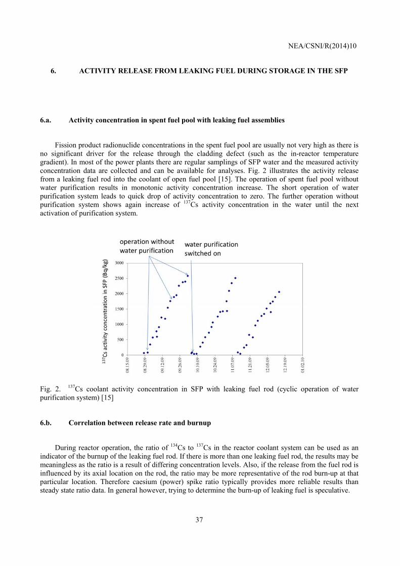
no significant driver for the release through the cladding defect (such as the in-reactor temperature gradient). In most of the power plants there are regular samplings of SFP water and the measured activity concentration data are collected and can be available for analyses. Fig. 2 illustrates the activity release from a leaking fuel rod into the coolant of open fuel pool [15]. The operation of spent fuel pool without water purification results in monotonic activity concentration increase. The short operation of water purification system leads to quick drop of activity concentration to zero. The further operation without purification system shows again increase of 137Cs activity concentration in the water until the next activation of purification system.
Fig. 2. 137Cs coolant activity concentration in SFP with leaking fuel rod (cyclic operation of water purification system) [15]
6.b. Correlation between release rate and burnup
During reactor operation, the ratio of 134Cs to 137Cs in the reactor coolant system can be used as an
indicator of the burnup of the leaking fuel rod. If there is more than one leaking fuel rod, the results may be meaningless as the ratio is a result of differing concentration levels. Also, if the release from the fuel rod is influenced by its axial location on the rod, the ratio may be more representative of the rod burn-up at that particular location. Therefore caesium (power) spike ratio typically provides more reliable results than steady state ratio data. In general however, trying to determine the burn-up of leaking fuel is speculative.
NEA/CSNI/R(2014)10
38
According to NPP data no correlation can be found between release rate in the SFP and burnup.
6.c. Correlation between release rate and storage time
Some measured data show that activity release from leaking in SFP decreases with time. Such data
may become available if only one single leaking assembly is stored in the SFP for long time.
The first days or weeks of wet storage may be characterised by significant activity release due to leaching of gap activity from the surface of cladding and pellet. Later the release rate correlates with the dissolution of UO2 in water and the release of long lived isotopes may be almost constant in time.
6.d. Correlation between release rate and leak size
Some correlations were established from experimental programs between the leak size and release
rate in SFP conditions [26].
Supporting data from NPP measurements are not known today. A special program with activity concentration measurements in SFP with leaking fuel and the visual examination of the damaged rod could provide such data.
NEA/CSNI/R(2014)10
39
7. ACTIVITY RELEASE FROM LEAKING FUEL DURING MANIPULATIONS IN THE SFP
7.a. Activity measurements during manipulations in SFP
The SFP activity concentrations are measured regularly at the NPPs (e.g. once per month or once a
week). Additional measurements are taken at many power plants during manipulations like lift of assembly, sipping, repair, handling and inspection work with the leaking fuel.
Typically these data are not collected for monitoring the release of radioactivity from leaking fuel assemblies, but for controlling the water quality of the spent fuel pool.
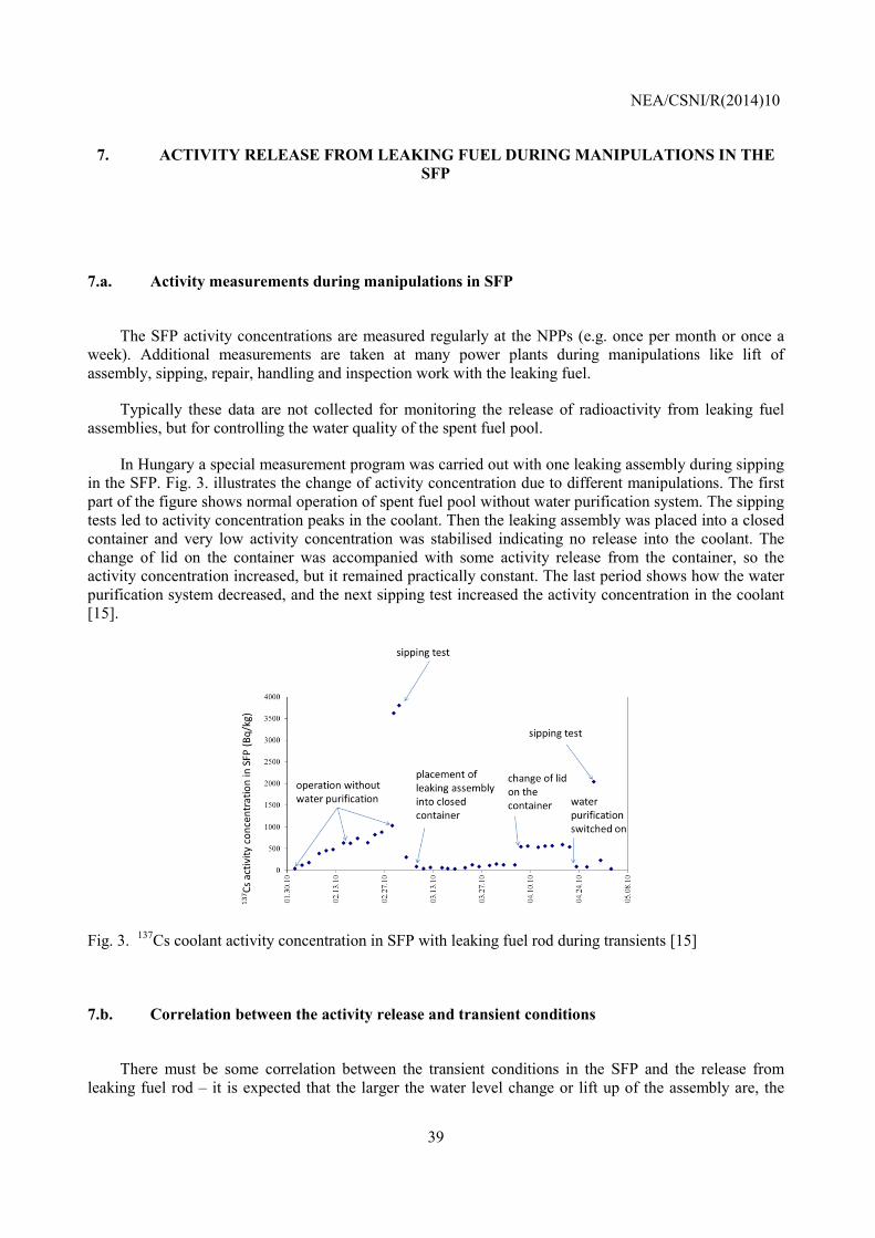
In Hungary a special measurement program was carried out with one leaking assembly during sipping in the SFP. Fig. 3. illustrates the change of activity concentration due to different manipulations. The first part of the figure shows normal operation of spent fuel pool without water purification system. The sipping tests led to activity concentration peaks in the coolant. Then the leaking assembly was placed into a closed container and very low activity concentration was stabilised indicating no release into the coolant. The change of lid on the container was accompanied with some activity release from the container, so the activity concentration increased, but it remained practically constant. The last period shows how the water purification system decreased, and the next sipping test increased the activity concentration in the coolant [15].
Fig. 3. 137Cs coolant activity concentration in SFP with leaking fuel rod during transients [15]
7.b. Correlation between the activity release and transient conditions
There must be some correlation between the transient conditions in the SFP and the release from
leaking fuel rod – it is expected that the larger the water level change or lift up of the assembly are, the
NEA/CSNI/R(2014)10
40
bigger the activity release will be. However, the available data do not show exact correlations. The operational conditions (water level range, lift up elevation) are limited in the SFP, for this reason most of the manipulations result in rather similar transient releases.
7.c. Fuel damage/fracture during the removal of leaking fuel rods
Extraction of a fuel rod that has experienced significant hydriding may be difficult, for the cladding at
the defect site may be very brittle. There have been cases where leaking rods have been fractured in an attempt to remove or view them.
Most of the time, the leaking rod is removed a long time after the core offload. As a consequence, there is no gas inventory left in the leaking rod and no additional activity release if the rod fractures during withdrawal from the fuel assembly. However, some fuel pellets may be lost due to the fracture of the hydrided rod.
In Belgium there were fractures at the end of the 1980s. Nowadays, an extractability analysis is performed before replacement and no fractures are observed.
NEA/CSNI/R(2014)10
41
8. TRANSPORT AND INTERIM STORAGE OF LEAKING FUEL ASSEMBLIES
8.a. Transport from the spent fuel pool to interim storage facilities
The transport of leaking fuel assemblies can be carried out in ordinary containers together with intact
assemblies in most of the countries. In Slovakia, special casks can be used for the transport of leaking fuel assemblies. Sending the leaking fuel assemblies or rods for hot cell examination may require special small size casks.
8.b. Activity release during transport to interim storage facility
The transport of leaking fuel assemblies produces only minor activity release. Normally the gas
volume of the container is not examined after transport. It can be supposed that more release is associated with the manipulations of loading and unloading of the containers, than with the transport itself.
8.c. Storage in wet facilities
In the countries where interim wet storage facilities are in operation, the leaking and intact assemblies
are normally stored together. In Slovakia, special containers (hermetic tubes) are available for the storage of leaking fuel assemblies.
In Sweden, no leaking fuel rods could be sent to the intermediate storage facility, but old BWR fuel can be accepted if inspected and documented to not leak any uranium. There are currently discussions about how leaking fuel assemblies should be treated in the future, considering final repository, intermediate storage facility (CLAB) and transportation.
8.d. Storage in dry facilities
The countries operating dry storage facilities follow different practices to handle leaking assemblies:
• In Switzerland, Belgium, Canada, and Czech Republic, no leaking fuel assemblies are stored in dry
storage facilities.
• In the US, fuel rods with “pinhole” defects or “hairline cracks” are typically allowed for dry storage without special canning or special handling. In instances whereby the leaking rod cannot be adequately characterized, it is stored in the same dry canister as intact fuel assemblies, but with
NEA/CSNI/R(2014)10
42
special mechanical devices or cans to prevent uncontrolled release of fuel material into the canister.
• In Germany, the damaged assemblies cannot be put in dry storage without being canned [4].
• In Hungary, the dry storage facility has a modular structure with individual storage tubes for each assembly. No special containers are used for leaking fuel assemblies, but they are stored in separate tubes from the intact assemblies.
NEA/CSNI/R(2014)10
43
9. ACTIVITY RELEASE FROM LEAKING FUEL IN INTERIM STORAGE FACILITIES
9.a. Activity measurements in wet storage facilities
In the interim wet storage facilities there are regular activity measurements, but the activity
concentration levels are normally very low. Even the manipulations do not lead to significant releases in the pools.
At the Slovak wet Interim Spent Fuel Storage Facility in the Jaslovske Bohunice nuclear power, an on-line detection system, based on a special sorbent for effective 134Cs and 137Cs activity, was developed to monitor the pool [16].
9.b. Activity measurements in dry storage facilities
The designs of dry storage facilities are very different, for this reason in many configurations the
sampling of gases and analyses of their content is not feasible. It would be very difficult to correlate the dose measurements at the interim storage site boundary to any release within the spent fuel dry storage system.
In those facilities where gas sampling is feasible, 85Kr activity can indicate the presence of leaking assemblies.

NEA/CSNI/R(2014)10
44
NEA/CSNI/R(2014)10
45
10. HYDROGEN GAS GENERATION FROM LEAKING FUEL IN DRY STORAGE FACILITIES
10.a. Hydrogen gas generation during transport
Hydrogen may be generated in systems that are not dry where radiolysis can occur with water and
high gamma flux. Furthermore the direct contact of water with the UO2 pellets can produce hydrogen due to the presence of α-emitting isotopes.
No hydrogen gas generation from Japanese leaking fuel rods during transport of fuel assemblies to hot experimental facilities or foreign reprocessing facilities has been observed.
In France, up to 2004 it was allowed to ship leaking NPP fuel assemblies only in dedicated canisters. Later the French Regulator (ASN) authorized the stakeholders to ship leaking fuel in normal casks, with no need to insert them into a sealed canister, but with the following restrictions:
o the cladding should be able to contain the fuel pellets, thus preventing any dispersal of fuel fragments outside the fuel assembly;
o the transport duration is limited to 60 days; o the total thermal power of the assemblies is limited to 50 kW.
In 2008, ASN modified the license certificates and required measurement of the H content prior to the
shipment (to quantify the risk for radiolysis) and to apply restrictions of the shipment duration for leaking assemblies depending on the H content measured. The reason for this change was based on the consideration of the risk of radiolysis of the residual water in the cask. AREVA carried out measurements of the H2 concentration in casks, which have been used to ship leaking assemblies and sound fuels. The measurements showed that H2 average content prior to the shipment was slightly higher in the casks which have been used to ship leaking fuel assemblies.
There are not any regulatory or managing rules in Japan to prevent generation of hydrogen gas from fuel rods during transport to the hot laboratories and reprocessing facilities.
In case of wet transport containers there might be some limitations in order to prevent explosion of hydrogen. The United Kingdom has extensive experience using re-combiners for transport and storage of intact fuel where, due to the large quantities of water present in the containers, there is a risk of significant and hazardous accumulation of hydrogen and oxygen [4].
10.b. Preventing accumulation of hydrogen in storage facilities
There are no regulatory criteria to prevent accumulation and/or generation of hydrogen gas from
leaking fuel rods during transport in the United States. The transportation systems require the primary container to be inertly dried, so no hydrogen gas is generated.
Other countries did not report any hydrogen accumulation criteria for storage facilities, either.

NEA/CSNI/R(2014)10
46
NEA/CSNI/R(2014)10
47
11. REPROCESSING OF LEAKING FUEL RODS
11.a. Experience of reprocessing leaking fuel
Leaking fuels are generally eligible for reprocessing. If reprocessing of normal fuel assemblies is
conducted for the given country (domestic or abroad), the leaking fuel can be reprocessed, too. If reprocessing is not applied for normal fuel, the reprocessing of leaking or damaged fuel takes place only in exceptional cases (e.g. in order to avoid the need for their long term storage).

NEA/CSNI/R(2014)10
48
NEA/CSNI/R(2014)10
49
12. EXPERIMENTAL INVESTIGATIONS OF LEAKING FUEL
12.a. Experimental facilities for the simulation of leaking process
The behaviour of defective fuel rods was investigated in several experimental programmes. Short
descriptions of some facilities and test programmes are given below.
CEA Siloe experiments with defective fuel (France)
A series of loop experiments have been performed on short fuel rods by CEA in France with the aim of measuring and interpreting the release rate of fission gases and iodine under a range of experimental conditions of linear power, defect type, gap dimensions etc. The experiments were all performed in the Siloe reactor in one of two water loops called Bouffon and Jet Pompe.
• The Bouffon loop consists of two vertical tubes connected at both ends to form a continuous circuit for pressurised water. The experimental fuel rod is situated in the bottom of one tube below a heater which provides an up current of water and hence by thermosyphoning, a flow of cooling water over the experimental fuel rod.
• The Jet Pompe loop comprises two co-axial vertical tubes. The experimental fuel rod is situated in the inner tube and coolant flow over it is provided by a steam injector pump at the bottom of the same tube. The steam at 400 °C and 35 bars is obtained from a steam generator installed elsewhere in the rig.
The release fractions of noble gases and iodine have been determined for different conditions: steady state power level between 120 and 700 W/cm, power cycling in the ranges of 200 to 400 W/cm and 120 to 400 W/cm. The power cycling favours the emission of iodine isotopes, the release rate of which is 10 to 20 times higher than at the maximum steady state power level [17, 18, 19, 20].
PBF experiments with defective fuel (USA)
Irradiation experiments with defective fuel rods have been conducted in the Power Burst Facility (PBF) at the Idaho National Engineering Laboratory in the 1970s. During these tests, the six rods lost cladding integrity prior to or during the transient phase of the test due to either manufacturing defects or intentional rod design and operation. Of the five defective rods tested under power-cooling-mismatch conditions, one had a hydride rupture below the region of the rod which was in film boiling during the transient, two contained defects (a pin hole and a small axial crack, respectively) within the film boiling zone, and two failed by cladding embrittlement within the film boiling zone.
According to the experimental results the behaviour of defective fuel rods depends primarily on whether the coolant has access to the interior of the portion of the rod which is in film boiling.
• If coolant access to the high-temperature rod interior does not exist, the consequences of operating a defective rod in a transient are not significantly different than those for intact rods in the same transient. The defective rod will, of course, release fission products to the coolant through the defect during the transient as well as during steady state operation.
NEA/CSNI/R(2014)10
50
• Fuel rods containing small cladding defects which allow coolant access to the rod interior within the region of the rod in film boiling are embrittled to a greater extent during the transients than are intact rods. These defective rods survive the quench upon rewet at the termination of film boiling, but fracture under post-test remote handling conditions due to embrittlement associated with hydrogen and oxygen in the cladding [21].
CRNL experiments with defective fuel (Canada)
To understand fuel defect performance and correlate fission product releases with sheath degradation, an irradiation program was carried out at the Chalk River Nuclear Laboratories (CRNL) from 1975 to 1983. This program was unique as both naturally and artificially defected rods were irradiated in an in-reactor test loop supplemented with on-line gamma-ray spectrometry. Failed fuel rods with various degree of sheath damage were irradiated in an experimental loop of the NRX reactor. Several rods were defected prior to irradiation with artificially drilled holes or machined slits in the cladding. In other experiments the defects were characteristic for failures found in power plant fuels (manufacturing and stress-corrosion-cracking type defects). The experimental loop was operated at the coolant conditions specified for CANDU reactors. The facility was designed to cope with high activity levels from fuel rods with large defects. The linear power ranged from 14 to 67 kW/m in the experiments, the maximum burn-up was 11.6 MWd/kgU. Both steady state and transient tests have been performed and the data was used to support the development of numerical defect fuel fission product release models [7, 22, 23].
VK-50 experiments with defective fuel (Russia)
Experiments with defective light water fuel rods were carried out in the VK-50 nuclear power plant with vessel type boiling water reactor. The purpose of the tests was to perform experimental investigation of the radioactive fission product release from defective fuel rods during power operation of water-cooled reactor including low linear power (5 to 12 kW/m) cases, to study the change of fission product release during long term irradiation and release from fuel-to-cladding gap into the coolant. The noble gas releases were determined from ejector discharges, while other fission products were measured in the coolant. Two experimental fuel assemblies were applied: three fuel rods in each assembly had through wall holes 0.9 to 1.0 mm diameter in the area of maximum linear power. The fuel burn-up at the end of irradiation was 15 and 18 MWd/kgU [24].
KWO Wet storage demonstration (Germany)
The aim of the test was to verify experimentally what was earlier theoretically predicted: the long term wet storage does not cause detectable changes on spent fuel. The experiments were executed in the spent fuel storage pool of the Obrigheim nuclear power plant. 28 spent fuel rods were included in the storage test. 18 of them were intact and 10 of them were operational defective rods. The first rod inspection was after reactor shutdown (1975) and after different periods of storage (1977 and 1980/81). The following methods were applied to characterise the spent fuel rods: visual inspection, profilometry, eddy current testing and oxide thickness measuring. The results of the different methods remained the same, no change exceeding the detection limits was detected, the differences were less than the standard deviation either at the intact or at the operational defective fuel rods. The experimental test corresponded well with the theoretical analysis. These results must be regarded as conservative because the handling of the defected spent fuel for inspections causing additional loads in contrary to the long term wet storage [25].
LEAFE leaking fuel experiments in wet storage conditions (Hungary)
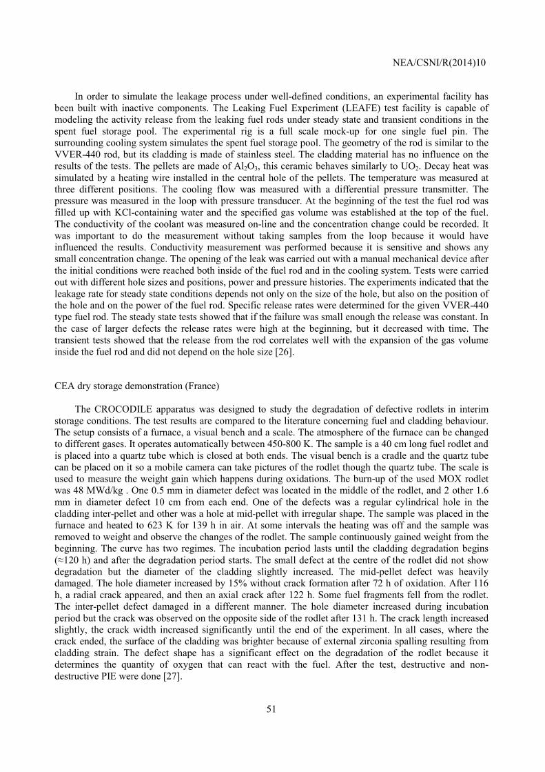
NEA/CSNI/R(2014)10
51
In order to simulate the leakage process under well-defined conditions, an experimental facility has been built with inactive components. The Leaking Fuel Experiment (LEAFE) test facility is capable of modeling the activity release from the leaking fuel rods under steady state and transient conditions in the spent fuel storage pool. The experimental rig is a full scale mock-up for one single fuel pin. The surrounding cooling system simulates the spent fuel storage pool. The geometry of the rod is similar to the VVER-440 rod, but its cladding is made of stainless steel. The cladding material has no influence on the results of the tests. The pellets are made of Al2O3, this ceramic behaves similarly to UO2. Decay heat was simulated by a heating wire installed in the central hole of the pellets. The temperature was measured at three different positions. The cooling flow was measured with a differential pressure transmitter. The pressure was measured in the loop with pressure transducer. At the beginning of the test the fuel rod was filled up with KCl-containing water and the specified gas volume was established at the top of the fuel. The conductivity of the coolant was measured on-line and the concentration change could be recorded. It was important to do the measurement without taking samples from the loop because it would have influenced the results. Conductivity measurement was performed because it is sensitive and shows any small concentration change. The opening of the leak was carried out with a manual mechanical device after the initial conditions were reached both inside of the fuel rod and in the cooling system. Tests were carried out with different hole sizes and positions, power and pressure histories. The experiments indicated that the leakage rate for steady state conditions depends not only on the size of the hole, but also on the position of the hole and on the power of the fuel rod. Specific release rates were determined for the given VVER-440 type fuel rod. The steady state tests showed that if the failure was small enough the release was constant. In the case of larger defects the release rates were high at the beginning, but it decreased with time. The transient tests showed that the release from the rod correlates well with the expansion of the gas volume inside the fuel rod and did not depend on the hole size [26].
CEA dry storage demonstration (France)
The CROCODILE apparatus was designed to study the degradation of defective rodlets in interim storage conditions. The test results are compared to the literature concerning fuel and cladding behaviour. The setup consists of a furnace, a visual bench and a scale. The atmosphere of the furnace can be changed to different gases. It operates automatically between 450-800 K. The sample is a 40 cm long fuel rodlet and is placed into a quartz tube which is closed at both ends. The visual bench is a cradle and the quartz tube can be placed on it so a mobile camera can take pictures of the rodlet though the quartz tube. The scale is used to measure the weight gain which happens during oxidations. The burn-up of the used MOX rodlet was 48 MWd/kg . One 0.5 mm in diameter defect was located in the middle of the rodlet, and 2 other 1.6 mm in diameter defect 10 cm from each end. One of the defects was a regular cylindrical hole in the cladding inter-pellet and other was a hole at mid-pellet with irregular shape. The sample was placed in the furnace and heated to 623 K for 139 h in air. At some intervals the heating was off and the sample was removed to weight and observe the changes of the rodlet. The sample continuously gained weight from the beginning. The curve has two regimes. The incubation period lasts until the cladding degradation begins (≈120 h) and after the degradation period starts. The small defect at the centre of the rodlet did not show degradation but the diameter of the cladding slightly increased. The mid-pellet defect was heavily damaged. The hole diameter increased by 15% without crack formation after 72 h of oxidation. After 116 h, a radial crack appeared, and then an axial crack after 122 h. Some fuel fragments fell from the rodlet. The inter-pellet defect damaged in a different manner. The hole diameter increased during incubation period but the crack was observed on the opposite side of the rodlet after 131 h. The crack length increased slightly, the crack width increased significantly until the end of the experiment. In all cases, where the crack ended, the surface of the cladding was brighter because of external zirconia spalling resulting from cladding strain. The defect shape has a significant effect on the degradation of the rodlet because it determines the quantity of oxygen that can react with the fuel. After the test, destructive and non-destructive PIE were done [27].
NEA/CSNI/R(2014)10
52
AECL CEX Dry Storage Experiments (Canada)
The Controlled Environment Experiment - Phase 1 (CEX-1) and Phase 2 (CEX-2) were performed to investigate degradation of irradiated CANDU fuel bundles at 423 K under conditions related to dry storage. The CEX-1 experiment used nominally dry air (dewpoint 288 K) and the CEX-2 experiment used moisture saturated air. All but one of the outer rods in four fuel bundles in each phase were deliberately defected by a single 3 mm hole in the cladding. The burn-ups of the outer rods ranged from 7.7 MWd/kgU to 10.8 MWd/kgU. The fuel rods were examined by optical microscopy, scanning electron microscopy, x-ray photoelectron spectroscopy (XPS) and x-ray powder diffraction (XRD).
The container atmosphere was significantly depleted in oxygen over the typical examination interval of several years. After 100 months (CEX-1) or 69 months (CEX-2) of limited exposure to air, no U3O8 was found in fuel rods in either experiment. The CEX-1 rods showed significant oxidation to U3O7/U4O9 close to the defect, and the CEX-2 rods showed more pervasive oxidation along the grain boundaries. The CEX-1 container was modified to increase the volume of air available for fuel oxidation, and rods were examined after a further 40 months of oxidation. The greatest local conversion of UO2 to U3O8 was 1.7%, and no significant fuel swelling or clad disruption had occurred [28,29].
NEA/CSNI/R(2014)10
53
13. SUMMARY
The impact and the practices of handling leaking nuclear fuel at the power plant and storage facilities
have been reviewed through a questionnaire with the participation of 15 countries. The results of the review showed that in most of the countries special attention is paid to the presence of leaking fuel rods in the core or in the storage facilities.
The leaking fuel rods are potential sources of activity release during normal operational conditions and also during accidents. The importance of this fact is well understood and the power plants limit their operation with leaking fuel through regulation of coolant activity concentrations and environmental releases.
The exchange of information proved very useful for the participants of the review. The summary of results may support the improvement of regulation and of handling practices in NPP operating countries.
The main conclusions of the review can be summarised as follows:
Impacts: • The leaking fuel rods release activity into coolant during normal operation. In case of a large
number of leaking rods the reactor should be shutdown and the leaking rods have to be removed from the core.
• During operational transients or accident conditions enhanced activity release can take place from leaking fuel rods even if no fuel failure takes place due to transient loads. The behaviour of intact and leaking fuel rods may differ during accidents: ballooning and burst cannot be expected in case of leaking rods, but the heavily hydrided cladding of leaking rods can fail at lower mechanical or thermal loads compared to intact rods.
• The storage of leaking fuel is normally characterised by low activity release, but in case of large fuel damage fragments can fall out from the rods and cause contamination in the storage facility. The transient conditions during storage may result in temporary increase of activity release from the leaking fuel rods.
Practices: • The power plants apply limits for activity concentration in the primary coolant, thus limiting
the number and degradation of leaking rods in the core. The limits are associated with different actions (increase of water purification rate, shutdown within a given time, limitation of power changes) in order to keep low activity concentration in the primary circuit.
• The accident analyses take into consideration the potential release from leaking fuel rods in many countries. In case of accidents with fuel failure the contribution of leaking fuel rods to activity release is regarded as negligible. In cases without fuel failure during the accident and with potential release into the environment, the spiking effect may play an important role. In most of the countries there are no specific regulatory criteria to address leaking fuel issues in design basis accidents (LOCA, RIA).
• The activity release from leaking fuel rods under different conditions (including steady state operation and transients in the reactor and in the storage facilities) was investigated in several experimental programmes. The activity measurements in the reactor, in the spent fuel pool and in the storage facilities provide direct information on the magnitude of activity release from leaking rods.
NEA/CSNI/R(2014)10
54
• The power plants apply different special tools for handling and repair of leaking assemblies and rods during storage in spent fuel pools. The storage of leaking rods and assemblies is carried out in most of the power plants together with intact assemblies.
• There are different practices on the interim storage of leaking fuel assemblies. In some countries, and in case of special facility designs, the leaking assemblies may be stored together with intact assemblies, while in other countries encapsulation or special casks are used to store leaking fuel.
• The final disposal of leaking fuel assemblies is under discussion in those countries where deep geological repositories will be constructed
Proposals:
• In order to compare the simulation of the role of leaking rods in accident conditions, benchmark calculations could be carried out (e.g. steam generator tube rupture accident without failure of fuel rods in the core, but with a given number of leaking fuel rods) to calculate activity release from leaking fuel using methods applied in different countries .
• The exchange of information on the techniques applied to handle leaking fuel assemblies and rods should be continued (e.g. specialists’ meetings with the participation of IAEA) in the future to find optimal solutions.
NEA/CSNI/R(2014)10
55
REFERENCES
1. Review of Fuel Failures in Water Cooled Reactors, IAEA Technical Reports, No. NF-T-2.1, IAEA
(2010) 2. Remote technology applications in spent fuel management, IAEA-TECDOC-1433, IAEA (2005) 3. Poolside inspection, repair and reconstitution of LWR fuel elements, IAEA-TECDOC-1050 IAEA
(1998) 4. Management of Damaged Spent Nuclear Fuel, IAEA Nuclear Energy Series No. NF-T3.6,
STI/PUB/1395, Vienna, 2009. 5. Nuclear Safety Rules for NPP Reactors (PBYa-Ryu-AS-89), Atomnaya Energiya 1990, vol.69. pp.
409-422. (in Russian) 6. Tigeras, A., Ambard, A., Laugier, F., Delcoigne, F., Muller, A., Fizames, N., 2005, MERLIN:
Modelling fuel defects at EDF power plants, Int. Conf. on Water Chemistry of Nuclear Reactor Systems, San Francisco, October 11-14, 2004, EPRI, Palo Alto, CA: 2005. 1011579, 1967-1977.
7. B.J. Lewis, J. Higgs, A. El-Jaby, W.T. Thompson, F.C. Iglesias, J. Armstrong, R. Stone, R. Oduntan:
2005, A model for predicting coolant activity behaviour for fuel-failure monitoring analysis, 9th Int. Conf on CANDU Fuel, Toronto, Ontario, Canada, 2005 Sep 18-21
8. M.H. Chun, N.I. Tak, S.K. Lee: 1998, Development of a computer code to estimate the fuel rod failure
using primary coolant activities of operating PWRs, Ann. Nucl. Ener. vol. 25, pp 753-763 9. P. Slavyagin, L. Lusanova, V. Miglo, Regulation of the fission product activity in the primary coolant
and assessment of defective fuel rod characteristics in steady-state WWER-type reactor operation, IAEA Technical meeting on fuel failure in water reactors: Causes and mitigation; Bratislava (Slovakia); 17-21 Jun 2002, IAEA-TECDOC-1345, pp 326-337.
10. V. Likhanskii, E. Afanasieva, A. Sorokin, I. Evdokimov, V. Kanukova, A. Khromov, Failed fuel
diagnosis during WWER reactor operation using the RTOP-CA code, 6th International conference on WWER fuel performance, modelling and experimental support; Albena, Bulgaria, 19-23 Sep 2005, 10p.
11. F. Pazdera, M. Valach, O. Barta, L. Novak, V. Stech, 1993, Application of the PES-PEPA expert
system at the Dukovany Nuclear Power Plant, Technical committee meeting on fuel failure in normal operation of water reactors: Experience, mechanisms and management; Dimitrovgrad (Russian Federation); 26-29 May 1992; IAEA-TECDOC—709, pp. 100-105
12. Z. Hózer: Simulation of leaking fuel rods in a VVER reactor, Annals of Nuclear Energy 70 (2014)
122–129. 13. A. B. Johnson Jr.: Behavior of Spent Nuclear Fuel in Water Pool Storage, Battelle, BNWL-2256, UC-
70, 1977,
NEA/CSNI/R(2014)10
56
14. http://sosnycompany.com/assessment_of_a_feasibility_and_practicality.html (download date: 10.06.2013)
15. T. Burján: Failed (Leaking) Spent Fuel Management and Storage in Paks NPP, Proc. 9th Int. Conf.
WWER Fuel Performance, Modelling and Experimental Support, 2011, pp. 132-139. 16. Marek Miklos, Miroslav Bozik, Daniel Vasina: Leak tightness testing system for nuclear fuel
assemblies in wet conditions of interim spent fuel storage, Int. J. of Nuclear Energy Science and Technology, 2007 Vol.3, No.3, pp. 220 – 235.
17. P. Chenebault, G. Kurka, A. Harrer, G. Lasne and M. Vivier: “Emission de Produits de Fission par un
Crayon Présentant une fuite de Conductance Elevée en Partie Haute et Soumis á Cyclage de Puissance, Expérience CYFON 1”, Compte-Rendu DMG No.103/77 (Fiche d'Action 4112) 30 Novembre 1977
18. Y. Kauffmann, Y. Barbier and M. Brun: “Examens aprés Irradiation de CYFON 1”, Compte-Rendu
DMG No.104/77 (Fiche d'Action 4112) 30 Novembre 1977 19. V.V. Likhanskii, I.A. Evdokimov, A.A. Sorokin, V.D. Kanukova (TRINITI): “Verification of the
RTOP-CA code against the OECD/NEA/IAEA IFPE database on activity release from defective fuel rods“
20. G. Kurka, A. Harrer, P. Chenebault : Fission Product Release from a Pressurized Water Reactor
Defective Fuel Rod : Effect of Thermal Cycling, Nuclear Technology, vol. 46, pp. 571-581, (1979) 21. R. R. Hobbins, D. W. Croucher, S. L. Seiffert, B. A. Cook, D. K. Kerwin, A. S. Mehner, and S. A.
Ploger: The behaviour of defective LWR-type fuel rods irradiated under postulated accident conditions, IAEA Specialists Meeting on Defected Zirconium Alloy Clad Ceramic Fuel in Water Cooled Reactors, Chalk River, Canada, September 17-21, 1979, pp. 161-166
22. B.J. Lewis: Fission Product Release from Defected Nuclear Reactor Fuel Elements, PhD Thesis,
1983, http://www.iaea.org/inis/collection/nclcollectionstore/_public/22/064/22064135.pdf 23. B.J. Lewis, R.D. MacDonald, N.I. Ivanoff, F.C. Iglesias : Fuel Performance and Fission Product
Release Studies for Defected Fuel Elements, Nuclear Technology, vol. 103, pp. 220-245, (1993) 24. V.V. Konyashov, A.M.Krasnov: Radioactive Fission Product Release From Defective Light Water
Reactor Fuel Elements, Nuclear Technology vol. 138 (2002), pp. 1-16. 25. M. Peehs, D. Jorde, H. Unger, J. Fleisch: Results of a long-term wet storage demonstration test with
intact and operational defective LWR fuel rods Nuclear Engineering and Design, Volume 83, Issue 1, November 1984, Pages 67-73
26. Barbara Somfai, Zoltán Hózer, Gergely Kracz, Imre Nagy, András Vimi: Simulation of leaking fuel
rods in the LEAFE Facility, TopFuel ‒ Reactor Fuel Performance Transactions 2012, 2-6 September 2012, Manchester, UK
27. L. Desgranges, M. P. Ferroud-Plattet, R. Alloncle, I. Aubrun, J. M. Untrau, P. Lhuillery: Behavior of
defective Nuclear Fuel Rod in Dry Storage Conditions Studied With a New Experimental Setup, Nuclear Technology, vol. 163 (2008), pp. 252-260.
NEA/CSNI/R(2014)10
57
28. P. Taylor, R.J. McEachern, S. Sunder, K.M. Wasywich, N.H. Miller and D.D. Wood, 1995, Recent findings on the oxidation of UO2 fuel under nominally dry storage conditions, Proc. 4th International Conference on CANDU Fuel, Pembroke, Ontario, Canada 1995 October 1-4, pp. 5A-66 - 5A-78 (AECL report AECL-11447)
29. W.H. Hocking, R. Behnke, A.M. Duclos, A.F. Gerwing and K.M. Wasywich, 1995, Grain-boundary
oxidation of used CANDU fuel exposed to dry air at 150°C for a prolonged period, Proc. 4th International Conference on CANDU Fuel, Pembroke, Ontario, Canada 1995 October 1-4, pp. 6B-20 – 6B-38

NEA/CSNI/R(2014)10
58
NEA/CSNI/R(2014)10
59
APPENDIX
List of original answers to the questionnaire Remarks Switzerland had three answers for some questions, they are specified as follows:
PWR W: PWR Westinghouse 2-loop 14x14, two blocks PWR S-K: PWR Siemens-KWU (3-Loop) BWR: BWR GE Mark III
Sweden had three answers for some questions, they are specified as follows:
FKA: Forsmark, 3 BWR (ASEA-Atom) RAB: Ringhals, 1 BWR and 3 PWR OKG: Oskarshamn, 3 BWR (ASEA-Atom
Canada had three answers for some questions, they are specified as follows:
BRUCE: Bruce Power OPG: Ontario Power Generation (with PNGS: Pickering Nuclear Generating Station and DNGS: Darlington Nuclear Generation Station) CNSC: Canadian Nuclear Safety Commission
USA provided the following references in addition to the answers:
[1] Fuel Reliability Monitoring and Failure Evaluation Handbook: Revision 2, Electric Power Research Institute Report 1019107 (November 2010)
[2] Nuclear Fuel Defects, Institute for Nuclear Power Operations Report SOER 90-2 (24 July 1990).
[3] Nuclear Fuel Behaviour in Loss-of-coolant Accident (LOCA) Conditions: State-of-the-art Report, OECD Nuclear Energy Agency Report 6846 (2009).
[4] Appendix B (Interim Acceptance Criteria and Guidance for the Reactivity Initiated Accidents) to Section 4.2 (Fuel System Design) of the NRC Standard Review Plan, NUREG-0800 (March 2007).
[5] Assumptions Used for Evaluating a Control Rod Ejection Accident for Pressurized Water Reactors, NRC Regulatory Guide 1.77 (May 1974).
[6] Fuel Reliability Guidelines: Fuel Surveillance and Inspection, Revision 1. Electric Power Research Institute Report 1024967 (March 2012).
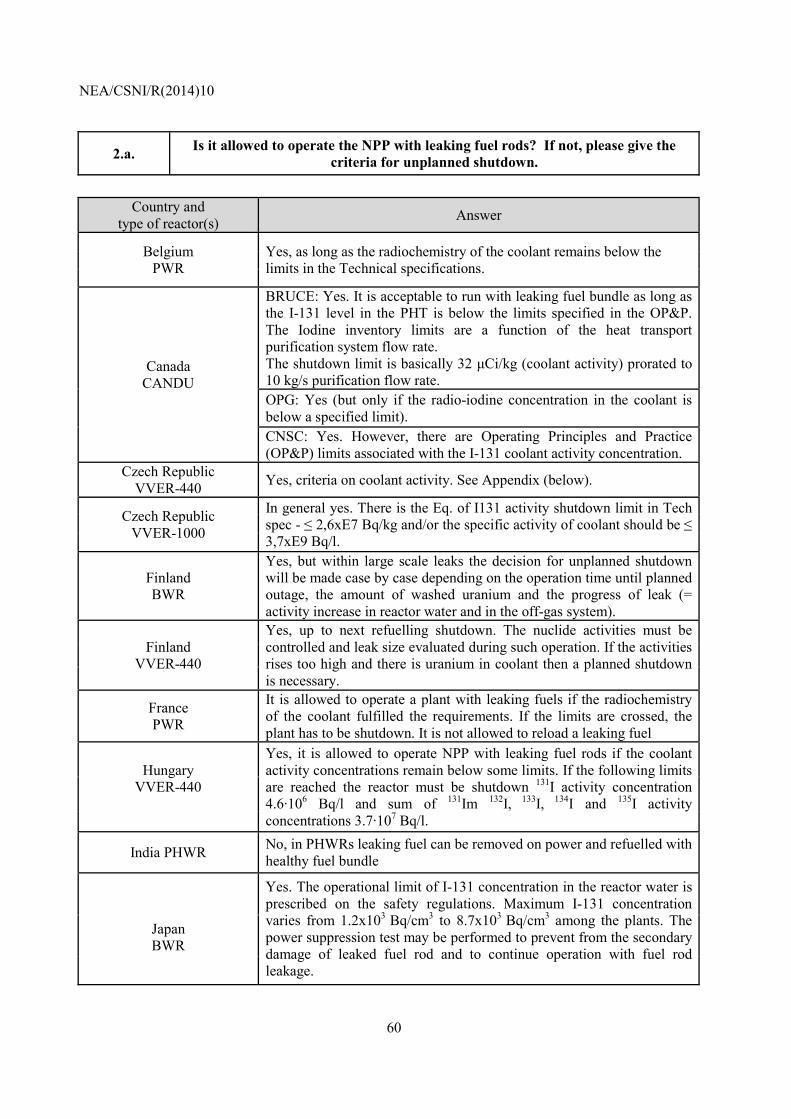
NEA/CSNI/R(2014)10
60
2.a. Is it allowed to operate the NPP with leaking fuel rods? If not, please give the criteria for unplanned shutdown.
Country and
type of reactor(s) Answer
Belgium PWR
Yes, as long as the radiochemistry of the coolant remains below the limits in the Technical specifications.
Canada CANDU
BRUCE: Yes. It is acceptable to run with leaking fuel bundle as long as the I-131 level in the PHT is below the limits specified in the OP&P. The Iodine inventory limits are a function of the heat transport purification system flow rate. The shutdown limit is basically 32 µCi/kg (coolant activity) prorated to 10 kg/s purification flow rate. OPG: Yes (but only if the radio-iodine concentration in the coolant is below a specified limit). CNSC: Yes. However, there are Operating Principles and Practice (OP&P) limits associated with the I-131 coolant activity concentration.
Czech Republic VVER-440 Yes, criteria on coolant activity. See Appendix (below).
Czech Republic VVER-1000
In general yes. There is the Eq. of I131 activity shutdown limit in Tech spec - ≤ 2,6xE7 Bq/kg and/or the specific activity of coolant should be ≤ 3,7xE9 Bq/l.
Finland BWR
Yes, but within large scale leaks the decision for unplanned shutdown will be made case by case depending on the operation time until planned outage, the amount of washed uranium and the progress of leak (= activity increase in reactor water and in the off-gas system).
Finland VVER-440
Yes, up to next refuelling shutdown. The nuclide activities must be controlled and leak size evaluated during such operation. If the activities rises too high and there is uranium in coolant then a planned shutdown is necessary.
France PWR
It is allowed to operate a plant with leaking fuels if the radiochemistry of the coolant fulfilled the requirements. If the limits are crossed, the plant has to be shutdown. It is not allowed to reload a leaking fuel
Hungary VVER-440
Yes, it is allowed to operate NPP with leaking fuel rods if the coolant activity concentrations remain below some limits. If the following limits are reached the reactor must be shutdown 131I activity concentration 4.6·106 Bq/l and sum of 131Im 132I, 133I, 134I and 135I activity concentrations 3.7·107 Bq/l.
India PHWR No, in PHWRs leaking fuel can be removed on power and refuelled with healthy fuel bundle
Japan BWR
Yes. The operational limit of I-131 concentration in the reactor water is prescribed on the safety regulations. Maximum I-131 concentration varies from 1.2x10³ Bq/cm3 to 8.7x10³ Bq/cm3 among the plants. The power suppression test may be performed to prevent from the secondary damage of leaked fuel rod and to continue operation with fuel rod leakage.
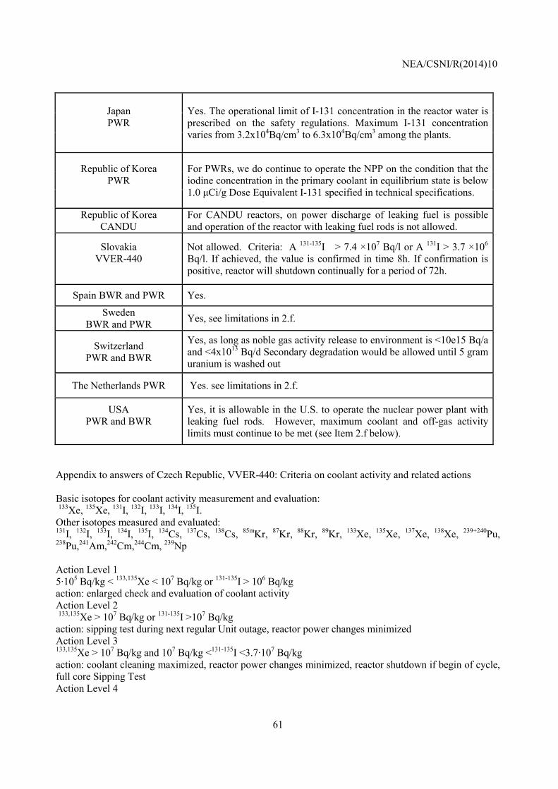
NEA/CSNI/R(2014)10
61
Japan PWR
Yes. The operational limit of I-131 concentration in the reactor water is prescribed on the safety regulations. Maximum I-131 concentration varies from 3.2x10⁴Bq/cm3 to 6.3x10⁴Bq/cm3 among the plants.
Republic of Korea PWR
For PWRs, we do continue to operate the NPP on the condition that the iodine concentration in the primary coolant in equilibrium state is below 1.0 µCi/g Dose Equivalent I-131 specified in technical specifications.
Republic of Korea CANDU
For CANDU reactors, on power discharge of leaking fuel is possible and operation of the reactor with leaking fuel rods is not allowed.
Slovakia VVER-440
Not allowed. Criteria: A 131-135I > 7.4 ×10⁷ Bq/l or A 131I > 3.7 ×10⁶ Bq/l. If achieved, the value is confirmed in time 8h. If confirmation is positive, reactor will shutdown continually for a period of 72h.
Spain BWR and PWR Yes.
Sweden BWR and PWR Yes, see limitations in 2.f.
Switzerland PWR and BWR
Yes, as long as noble gas activity release to environment is <10e15 Bq/a and <4x10¹³ Bq/d Secondary degradation would be allowed until 5 gram uranium is washed out
The Netherlands PWR Yes. see limitations in 2.f.
USA PWR and BWR
Yes, it is allowable in the U.S. to operate the nuclear power plant with leaking fuel rods. However, maximum coolant and off-gas activity limits must continue to be met (see Item 2.f below).
Appendix to answers of Czech Republic, VVER-440: Criteria on coolant activity and related actions Basic isotopes for coolant activity measurement and evaluation: 133Xe, 135Xe, 131I, 132I, 133I, 134I, 135I. Other isotopes measured and evaluated: 131I, 132I, 133I, 134I, 135I, 134Cs, 137Cs, 138Cs, 85mKr, 87Kr, 88Kr, 89Kr, 133Xe, 135Xe, 137Xe, 138Xe, 239+240Pu, 238Pu,241Am,242Cm,244Cm, 239Np Action Level 1 5·105 Bq/kg < 133,135Xe < 107 Bq/kg or 131-135I > 106 Bq/kg action: enlarged check and evaluation of coolant activity Action Level 2 133,135Xe > 107 Bq/kg or 131-135I >107 Bq/kg action: sipping test during next regular Unit outage, reactor power changes minimized Action Level 3 133,135Xe > 107 Bq/kg and 107 Bq/kg <131-135I <3.7·107 Bq/kg action: coolant cleaning maximized, reactor power changes minimized, reactor shutdown if begin of cycle, full core Sipping Test Action Level 4
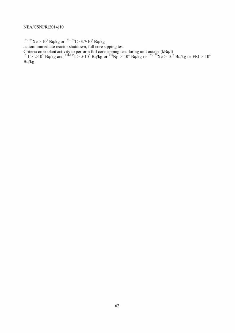
NEA/CSNI/R(2014)10
62
133,135Xe > 108 Bq/kg or 131-135I > 3.7·107 Bq/kg action: immediate reactor shutdown, full core sipping test Criteria on coolant activity to perform full core sipping test during unit outage (kBq/l) 131I > 2·105 Bq/kg and 131-135I > 5·105 Bq/kg or 239Np > 104 Bq/kg or 133-135Xe > 107 Bq/kg or FRI > 104 Bq/kg
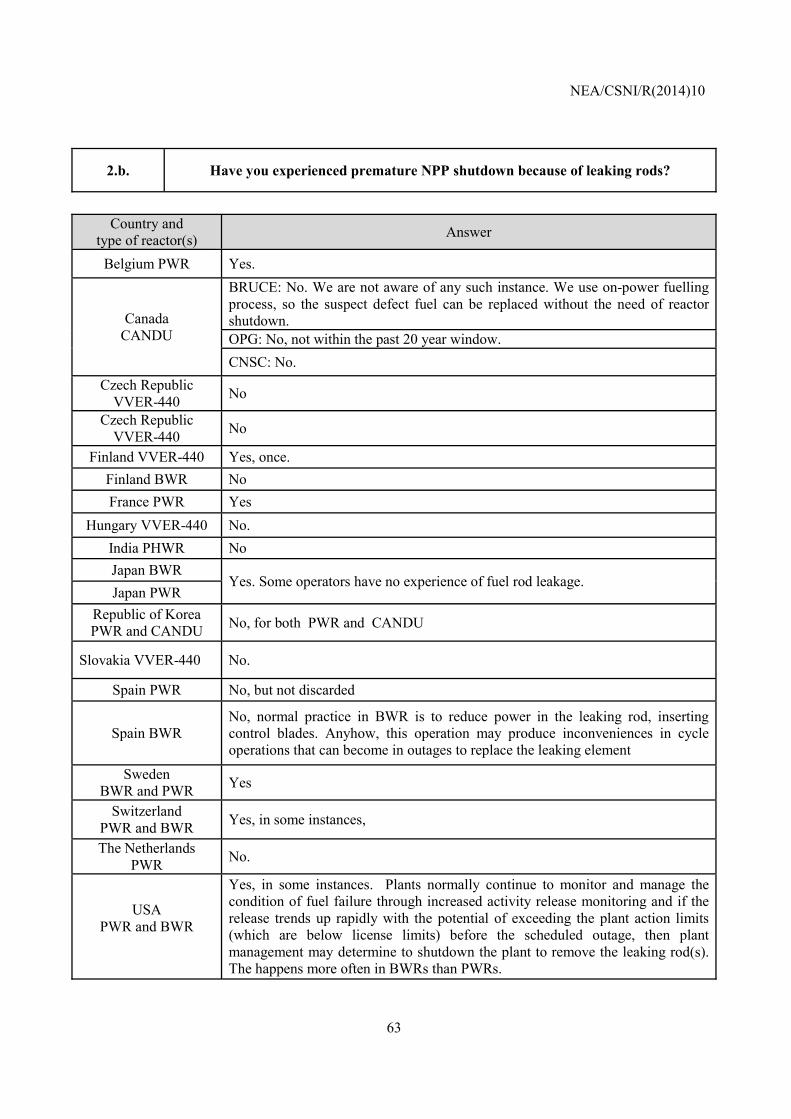
NEA/CSNI/R(2014)10
63
2.b. Have you experienced premature NPP shutdown because of leaking rods?
Country and
type of reactor(s) Answer
Belgium PWR Yes.
Canada CANDU
BRUCE: No. We are not aware of any such instance. We use on-power fuelling process, so the suspect defect fuel can be replaced without the need of reactor shutdown. OPG: No, not within the past 20 year window. CNSC: No.
Czech Republic VVER-440 No
Czech Republic VVER-440 No
Finland VVER-440 Yes, once. Finland BWR No France PWR Yes
Hungary VVER-440 No. India PHWR No Japan BWR
Yes. Some operators have no experience of fuel rod leakage. Japan PWR
Republic of Korea PWR and CANDU No, for both PWR and CANDU
Slovakia VVER-440 No.
Spain PWR No, but not discarded
Spain BWR No, normal practice in BWR is to reduce power in the leaking rod, inserting control blades. Anyhow, this operation may produce inconveniences in cycle operations that can become in outages to replace the leaking element
Sweden BWR and PWR Yes
Switzerland PWR and BWR Yes, in some instances,
The Netherlands PWR No.
USA PWR and BWR
Yes, in some instances. Plants normally continue to monitor and manage the condition of fuel failure through increased activity release monitoring and if the release trends up rapidly with the potential of exceeding the plant action limits (which are below license limits) before the scheduled outage, then plant management may determine to shutdown the plant to remove the leaking rod(s). The happens more often in BWRs than PWRs.
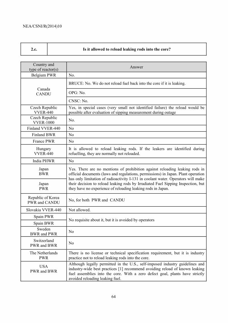
NEA/CSNI/R(2014)10
64
2.c. Is it allowed to reload leaking rods into the core?
Country and
type of reactor(s) Answer
Belgium PWR No.
Canada CANDU
BRUCE: No. We do not reload fuel back into the core if it is leaking.
OPG: No.
CNSC: No. Czech Republic
VVER-440 Yes, in special cases (very small not identified failure) the reload would be possible after evaluation of sipping measurement during outage
Czech Republic VVER-1000 No.
Finland VVER-440 No Finland BWR No France PWR No
Hungary VVER-440
It is allowed to reload leaking rods. If the leakers are identified during refuelling, they are normally not reloaded.
India PHWR No
Japan BWR
Yes. There are no mentions of prohibition against reloading leaking rods in official documents (laws and regulations, permissions) in Japan. Plant operation has only limitation of radioactivity I-131 in coolant water. Operators will make their decision to reload leaking rods by Irradiated Fuel Sipping Inspection, but they have no experience of reloading leaking rods in Japan.
Japan PWR
Republic of Korea PWR and CANDU No, for both PWR and CANDU
Slovakia VVER-440 Not allowed. Spain PWR
No requisite about it, but it is avoided by operators Spain BWR
Sweden BWR and PWR No
Switzerland PWR and BWR No
The Netherlands PWR
There is no license or technical specification requirement, but it is industry practice not to reload leaking rods into the core.
USA PWR and BWR
Although legally permitted in the U.S., self-imposed industry guidelines and industry-wide best practices [1] recommend avoiding reload of known leaking fuel assemblies into the core. With a zero defect goal, plants have strictly avoided reloading leaking fuel.
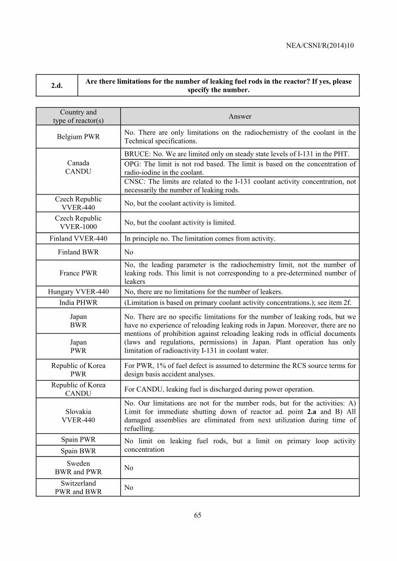
NEA/CSNI/R(2014)10
65
2.d. Are there limitations for the number of leaking fuel rods in the reactor? If yes, please specify the number.
Country and
type of reactor(s) Answer
Belgium PWR No. There are only limitations on the radiochemistry of the coolant in the Technical specifications.
Canada CANDU
BRUCE: No. We are limited only on steady state levels of I-131 in the PHT. OPG: The limit is not rod based. The limit is based on the concentration of radio-iodine in the coolant. CNSC: The limits are related to the I-131 coolant activity concentration, not necessarily the number of leaking rods.
Czech Republic VVER-440 No, but the coolant activity is limited.
Czech Republic VVER-1000 No, but the coolant activity is limited.
Finland VVER-440 In principle no. The limitation comes from activity.
Finland BWR No
France PWR No, the leading parameter is the radiochemistry limit, not the number of leaking rods. This limit is not corresponding to a pre-determined number of leakers
Hungary VVER-440 No, there are no limitations for the number of leakers. India PHWR (Limitation is based on primary coolant activity concentrations.); see item 2f.
Japan BWR
No. There are no specific limitations for the number of leaking rods, but we have no experience of reloading leaking rods in Japan. Moreover, there are no mentions of prohibition against reloading leaking rods in official documents (laws and regulations, permissions) in Japan. Plant operation has only limitation of radioactivity I-131 in coolant water.
Japan PWR
Republic of Korea PWR
For PWR, 1% of fuel defect is assumed to determine the RCS source terms for design basis accident analyses.
Republic of Korea CANDU For CANDU, leaking fuel is discharged during power operation.
Slovakia
VVER-440
No. Our limitations are not for the number rods, but for the activities: A) Limit for immediate shutting down of reactor ad. point 2.a and B) All damaged assemblies are eliminated from next utilization during time of refuelling.
Spain PWR No limit on leaking fuel rods, but a limit on primary loop activity concentration Spain BWR
Sweden BWR and PWR No
Switzerland PWR and BWR No
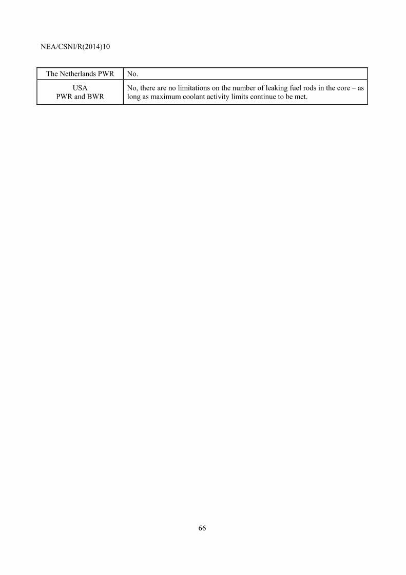
NEA/CSNI/R(2014)10
66
The Netherlands PWR No.
USA PWR and BWR
No, there are no limitations on the number of leaking fuel rods in the core – as long as maximum coolant activity limits continue to be met.
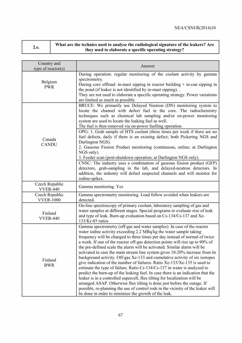
NEA/CSNI/R(2014)10
67
2.e. What are the technics used to analyse the radiological signature of the leakers? Are they used to elaborate a specific operating strategy?
Country and
type of reactor(s) Answer
Belgium PWR
During operation: regular monitoring of the coolant activity by gamma spectrometry. During core offload: in-mast sipping in reactor building + in-can sipping in the pond (if leaker is not identified by in-mast sipping). . They are not used to elaborate a specific operating strategy. Power variations are limited as much as possible.
Canada CANDU
BRUCE: We primarily use Delayed Neutron (DN) monitoring system to locate the channel with defect fuel in the core. The radiochemistry techniques such as chemical lab sampling and/or on-power monitoring system are used to locate the leaking fuel as well. The fuel is then removed via on-power fuelling operation. OPG: 1. Grab sample of HTS coolant (three times per week if there are no fuel defects, daily if there is an existing defect; both Pickering NGS and Darlington NGS). 2. Gaseous Fission Product monitoring (continuous, online; at Darlington NGS only). 3. Feeder scan (post-shutdown operation; at Darlington NGS only). CNSC: The industry uses a combination of gaseous fission product (GFP) detectors, grab-sampling in the lab, and delayed-neutron detectors. In addition, the industry will defuel suspected channels and will monitor for iodine-spikes.
Czech Republic VVER-440 Gamma monitoring. Yes
Czech Republic VVER-1000
Gamma spectrometry monitoring. Load follow avoided when leakers are detected.
Finland
VVER-440
On-line spectroscopy of primary coolant, laboratory sampling of gas and water samples at different stages. Special programs to evaluate size of leak and type of leak. Burn-up evaluation based on Cs-134/Cs-137 and Xe-133/Kr-85 ratios
Finland BWR
Gamma spectrometry (off-gas and water samples). In case of the reactor water iodine activity exceeding 2.2 MBq/kg the water sample taking frequency will be changed to three times per day instead of normal of twice a week. If one of the reactor off-gas detection points will rise up to 90% of the pre-defined scale the alarm will be activated. Similar alarm will be activated in case the main stream line system gives 10-20% increase from its background activity. Off-gas Xe-133 and cumulative activity of six isotopes give indication of the number of failures. Ratio Xe-133/Xe-135 is used to estimate the type of failure. Ratio Cs-134/Cs-137 in water is analyzed to predict the burn-up of the leaking fuel. In case there is an indication that the leaker is in a controlled supercell, flux tilting for localization will be arranged ASAP. Otherwise flux tilting is done just before the outage. If possible, re-planning the use of control rods in the vicinity of the leaker will be done in order to minimize the growth of the leak.
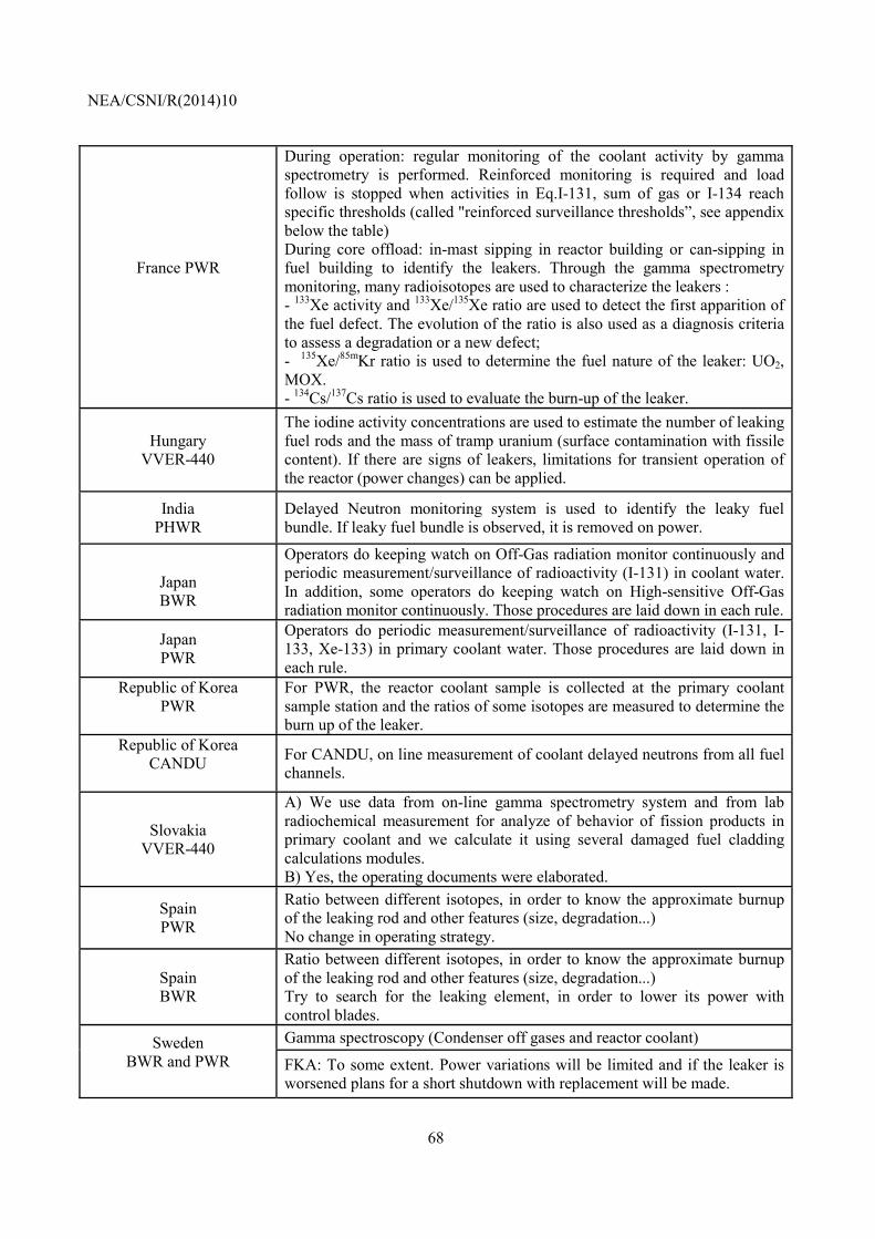
NEA/CSNI/R(2014)10
68
France PWR
During operation: regular monitoring of the coolant activity by gamma spectrometry is performed. Reinforced monitoring is required and load follow is stopped when activities in Eq.I-131, sum of gas or I-134 reach specific thresholds (called "reinforced surveillance thresholds”, see appendix below the table) During core offload: in-mast sipping in reactor building or can-sipping in fuel building to identify the leakers. Through the gamma spectrometry monitoring, many radioisotopes are used to characterize the leakers : - 133Xe activity and 133Xe/135Xe ratio are used to detect the first apparition of the fuel defect. The evolution of the ratio is also used as a diagnosis criteria to assess a degradation or a new defect; - 135Xe/85mKr ratio is used to determine the fuel nature of the leaker: UO2, MOX. - 134Cs/137Cs ratio is used to evaluate the burn-up of the leaker.
Hungary VVER-440
The iodine activity concentrations are used to estimate the number of leaking fuel rods and the mass of tramp uranium (surface contamination with fissile content). If there are signs of leakers, limitations for transient operation of the reactor (power changes) can be applied.
India PHWR
Delayed Neutron monitoring system is used to identify the leaky fuel bundle. If leaky fuel bundle is observed, it is removed on power.
Japan BWR
Operators do keeping watch on Off-Gas radiation monitor continuously and periodic measurement/surveillance of radioactivity (I-131) in coolant water. In addition, some operators do keeping watch on High-sensitive Off-Gas radiation monitor continuously. Those procedures are laid down in each rule.
Japan PWR
Operators do periodic measurement/surveillance of radioactivity (I-131, I-133, Xe-133) in primary coolant water. Those procedures are laid down in each rule.
Republic of Korea PWR
For PWR, the reactor coolant sample is collected at the primary coolant sample station and the ratios of some isotopes are measured to determine the burn up of the leaker.
Republic of Korea CANDU
For CANDU, on line measurement of coolant delayed neutrons from all fuel channels.
Slovakia
VVER-440
A) We use data from on-line gamma spectrometry system and from lab radiochemical measurement for analyze of behavior of fission products in primary coolant and we calculate it using several damaged fuel cladding calculations modules. B) Yes, the operating documents were elaborated.
Spain PWR
Ratio between different isotopes, in order to know the approximate burnup of the leaking rod and other features (size, degradation...) No change in operating strategy.
Spain BWR
Ratio between different isotopes, in order to know the approximate burnup of the leaking rod and other features (size, degradation...) Try to search for the leaking element, in order to lower its power with control blades.
Sweden BWR and PWR
Gamma spectroscopy (Condenser off gases and reactor coolant)
FKA: To some extent. Power variations will be limited and if the leaker is worsened plans for a short shutdown with replacement will be made.
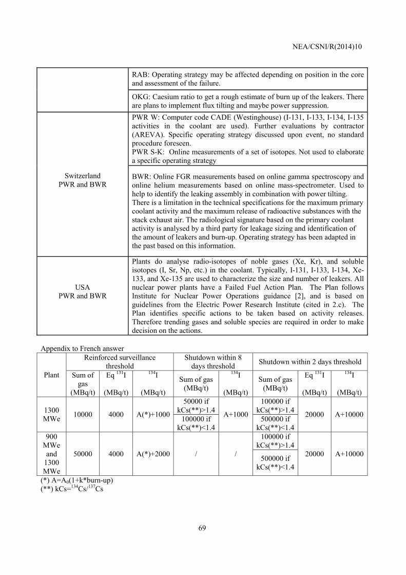
NEA/CSNI/R(2014)10
69
RAB: Operating strategy may be affected depending on position in the core and assessment of the failure.
OKG: Caesium ratio to get a rough estimate of burn up of the leakers. There are plans to implement flux tilting and maybe power suppression.
Switzerland PWR and BWR
PWR W: Computer code CADE (Westinghouse) (I-131, I-133, I-134, I-135 activities in the coolant are used). Further evaluations by contractor (AREVA). Specific operating strategy discussed upon event, no standard procedure foreseen. PWR S-K: Online measurements of a set of isotopes. Not used to elaborate a specific operating strategy
BWR: Online FGR measurements based on online gamma spectroscopy and online helium measurements based on online mass-spectrometer. Used to help to identify the leaking assembly in combination with power tilting. There is a limitation in the technical specifications for the maximum primary coolant activity and the maximum release of radioactive substances with the stack exhaust air. The radiological signature based on the primary coolant activity is analysed by a third party for leakage sizing and identification of the amount of leakers and burn-up. Operating strategy has been adapted in the past based on this information.
USA PWR and BWR
Plants do analyse radio-isotopes of noble gases (Xe, Kr), and soluble isotopes (I, Sr, Np, etc.) in the coolant. Typically, I-131, I-133, I-134, Xe-133, and Xe-135 are used to characterize the size and number of leakers. All nuclear power plants have a Failed Fuel Action Plan. The Plan follows Institute for Nuclear Power Operations guidance [2], and is based on guidelines from the Electric Power Research Institute (cited in 2.c). The Plan identifies specific actions to be taken based on activity releases. Therefore trending gases and soluble species are required in order to make decision on the actions.
Appendix to French answer
Plant
Reinforced surveillance threshold
Shutdown within 8 days threshold Shutdown within 2 days threshold
Sum of gas
(MBq/t)
Eq 131I
(MBq/t)
134I
(MBq/t)
Sum of gas (MBq/t)
134I
(MBq/t)
Sum of gas (MBq/t)
Eq 131I
(MBq/t)
134I
(MBq/t)
1300 MWe 10000 4000 A(*)+1000
50000 if kCs(**)>1.4 A+1000
100000 if kCs(**)>1.4 20000 A+10000 100000 if
kCs(**)<1.4500000 if
kCs(**)<1.4 900
MWe and
1300 MWe
50000 4000 A(*)+2000 / /
100000 if kCs(**)>1.4
20000 A+10000 500000 if kCs(**)<1.4
(*) A=A0(1+k*burn-up) (**) kCs=134Cs/137Cs
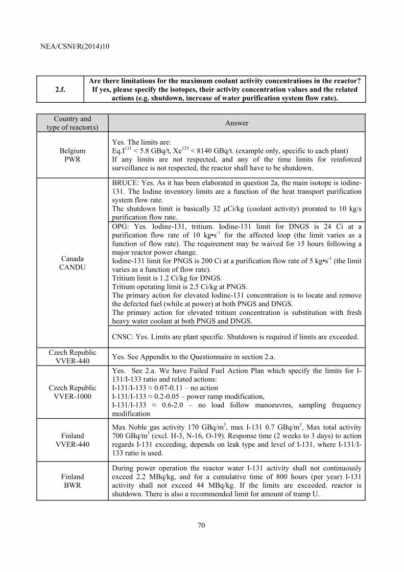
NEA/CSNI/R(2014)10
70
2.f. Are there limitations for the maximum coolant activity concentrations in the reactor? If yes, please specify the isotopes, their activity concentration values and the related
actions (e.g. shutdown, increase of water purification system flow rate).
Country and type of reactor(s) Answer
Belgium PWR
Yes. The limits are: Eq.I131 < 5.8 GBq/t, Xe133 < 8140 GBq/t. (example only, specific to each plant) If any limits are not respected, and any of the time limits for reinforced surveillance is not respected, the reactor shall have to be shutdown.
Canada CANDU
BRUCE: Yes. As it has been elaborated in question 2a, the main isotope is iodine-131. The Iodine inventory limits are a function of the heat transport purification system flow rate. The shutdown limit is basically 32 µCi/kg (coolant activity) prorated to 10 kg/s purification flow rate. OPG: Yes. Iodine-131, tritium. Iodine-131 limit for DNGS is 24 Ci at a purification flow rate of 10 kg•s-1 for the affected loop (the limit varies as a function of flow rate). The requirement may be waived for 15 hours following a major reactor power change. Iodine-131 limit for PNGS is 200 Ci at a purification flow rate of 5 kg•s-1 (the limit varies as a function of flow rate). Tritium limit is 1.2 Ci/kg for DNGS. Tritium operating limit is 2.5 Ci/kg at PNGS. The primary action for elevated Iodine-131 concentration is to locate and remove the defected fuel (while at power) at both PNGS and DNGS. The primary action for elevated tritium concentration is substitution with fresh heavy water coolant at both PNGS and DNGS.
CNSC: Yes. Limits are plant specific. Shutdown is required if limits are exceeded.
Czech Republic VVER-440 Yes. See Appendix to the Questionnaire in section 2.a.
Czech Republic VVER-1000
Yes. See 2.a. We have Failed Fuel Action Plan which specify the limits for I-131/I-133 ratio and related actions: I-131/I-133 ≈ 0.07-0.11 – no action I-131/I-133 ≈ 0.2-0.05 – power ramp modification, I-131/I-133 ≈ 0.6-2.0 – no load follow manoeuvres, sampling frequency modification
Finland VVER-440
Max Noble gas activity 170 GBq/m3, max I-131 0.7 GBq/m3, Max total activity 700 GBq/m3 (excl. H-3, N-16, O-19). Response time (2 weeks to 3 days) to action regards I-131 exceeding, depends on leak type and level of I-131, where I-131/I-133 ratio is used.
Finland BWR
During power operation the reactor water I-131 activity shall not continuously exceed 2.2 MBq/kg, and for a cumulative time of 800 hours (per year) I-131 activity shall not exceed 44 MBq/kg. If the limits are exceeded, reactor is shutdown. There is also a recommended limit for amount of tramp U.
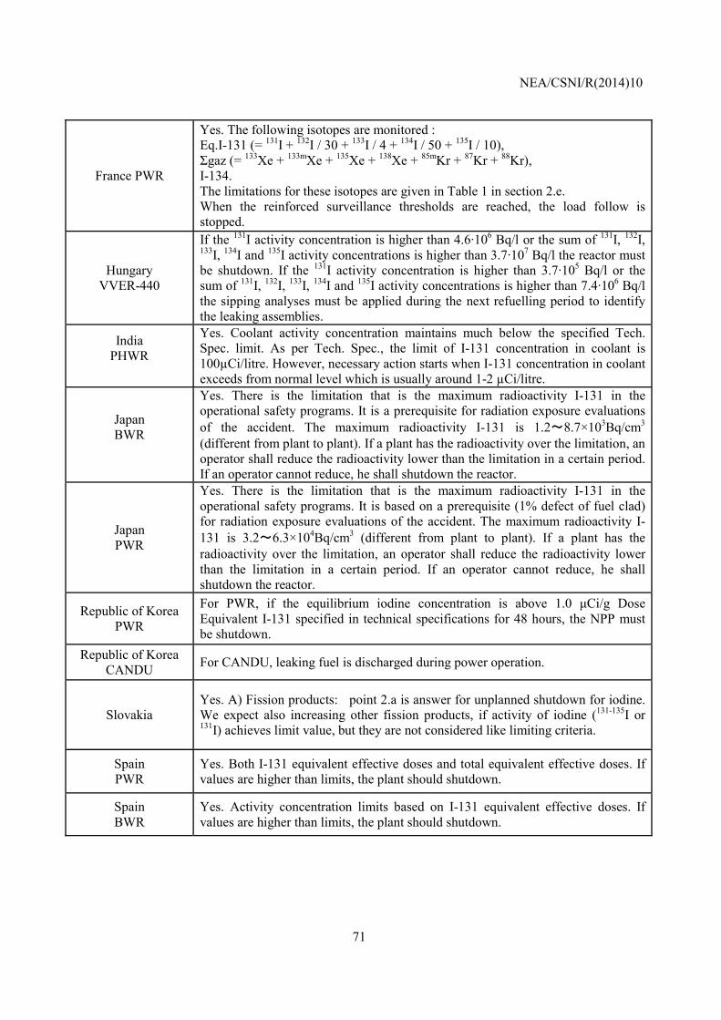
NEA/CSNI/R(2014)10
71
France PWR
Yes. The following isotopes are monitored : Eq.I-131 (= 131I + 132I / 30 + 133I / 4 + 134I / 50 + 135I / 10), Σgaz (= 133Xe + 133mXe + 135Xe + 138Xe + 85mKr + 87Kr + 88Kr), I-134. The limitations for these isotopes are given in Table 1 in section 2.e. When the reinforced surveillance thresholds are reached, the load follow is stopped.
Hungary VVER-440
If the 131I activity concentration is higher than 4.6·106 Bq/l or the sum of 131I, 132I, 133I, 134I and 135I activity concentrations is higher than 3.7·107 Bq/l the reactor must be shutdown. If the 131I activity concentration is higher than 3.7·105 Bq/l or the sum of 131I, 132I, 133I, 134I and 135I activity concentrations is higher than 7.4·106 Bq/l the sipping analyses must be applied during the next refuelling period to identify the leaking assemblies.
India PHWR
Yes. Coolant activity concentration maintains much below the specified Tech. Spec. limit. As per Tech. Spec., the limit of I-131 concentration in coolant is 100µCi/litre. However, necessary action starts when I-131 concentration in coolant exceeds from normal level which is usually around 1-2 µCi/litre.
Japan BWR
Yes. There is the limitation that is the maximum radioactivity I-131 in the operational safety programs. It is a prerequisite for radiation exposure evaluations of the accident. The maximum radioactivity I-131 is 1.2~8.7×10³Bq/cm3
(different from plant to plant). If a plant has the radioactivity over the limitation, an operator shall reduce the radioactivity lower than the limitation in a certain period. If an operator cannot reduce, he shall shutdown the reactor.
Japan PWR
Yes. There is the limitation that is the maximum radioactivity I-131 in the operational safety programs. It is based on a prerequisite (1% defect of fuel clad) for radiation exposure evaluations of the accident. The maximum radioactivity I-131 is 3.2~6.3×10⁴Bq/cm3 (different from plant to plant). If a plant has the radioactivity over the limitation, an operator shall reduce the radioactivity lower than the limitation in a certain period. If an operator cannot reduce, he shall shutdown the reactor.
Republic of Korea PWR
For PWR, if the equilibrium iodine concentration is above 1.0 µCi/g Dose Equivalent I-131 specified in technical specifications for 48 hours, the NPP must be shutdown.
Republic of Korea CANDU For CANDU, leaking fuel is discharged during power operation.
Slovakia Yes. A) Fission products: point 2.a is answer for unplanned shutdown for iodine. We expect also increasing other fission products, if activity of iodine (131-135I or 131I) achieves limit value, but they are not considered like limiting criteria.
Spain PWR
Yes. Both I-131 equivalent effective doses and total equivalent effective doses. If values are higher than limits, the plant should shutdown.
Spain BWR
Yes. Activity concentration limits based on I-131 equivalent effective doses. If values are higher than limits, the plant should shutdown.
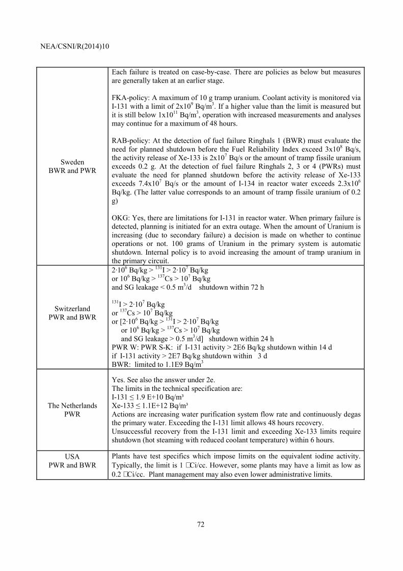
NEA/CSNI/R(2014)10
72
Sweden BWR and PWR
Each failure is treated on case-by-case. There are policies as below but measures are generally taken at an earlier stage. FKA-policy: A maximum of 10 g tramp uranium. Coolant activity is monitored via I-131 with a limit of 2x10⁹ Bq/m3. If a higher value than the limit is measured but it is still below 1x10¹¹ Bq/m3, operation with increased measurements and analyses may continue for a maximum of 48 hours. RAB-policy: At the detection of fuel failure Ringhals 1 (BWR) must evaluate the need for planned shutdown before the Fuel Reliability Index exceed 3x10⁸ Bq/s, the activity release of Xe-133 is 2x10⁷ Bq/s or the amount of tramp fissile uranium exceeds 0.2 g. At the detection of fuel failure Ringhals 2, 3 or 4 (PWRs) must evaluate the need for planned shutdown before the activity release of Xe-133 exceeds 7.4x10⁷ Bq/s or the amount of I-134 in reactor water exceeds 2.3x10⁶ Bq/kg. (The latter value corresponds to an amount of tramp fissile uranium of 0.2 g) OKG: Yes, there are limitations for I-131 in reactor water. When primary failure is detected, planning is initiated for an extra outage. When the amount of Uranium is increasing (due to secondary failure) a decision is made on whether to continue operations or not. 100 grams of Uranium in the primary system is automatic shutdown. Internal policy is to avoid increasing the amount of tramp uranium in the primary circuit.
Switzerland PWR and BWR
2·106 Bq/kg > 131I > 2·107 Bq/kg or 106 Bq/kg > 137Cs > 107 Bq/kg and SG leakage < 0.5 m3/d shutdown within 72 h 131I > 2·107 Bq/kg or 137Cs > 107 Bq/kg or [2·106 Bq/kg > 131I > 2·107 Bq/kg or 106 Bq/kg > 137Cs > 107 Bq/kg and SG leakage > 0.5 m3/d] shutdown within 24 h PWR W: PWR S-K: if I-131 activity > 2E6 Bq/kg shutdown within 14 d if I-131 activity > 2E7 Bq/kg shutdown within 3 d BWR: limited to 1.1E9 Bq/m3
The Netherlands PWR
Yes. See also the answer under 2e. The limits in the technical specification are: I-131 ≤ 1.9 E+10 Bq/m³ Xe-133 ≤ 1.1E+12 Bq/m³ Actions are increasing water purification system flow rate and continuously degas the primary water. Exceeding the I-131 limit allows 48 hours recovery. Unsuccessful recovery from the I-131 limit and exceeding Xe-133 limits require shutdown (hot steaming with reduced coolant temperature) within 6 hours.
USA PWR and BWR
Plants have test specifics which impose limits on the equivalent iodine activity. Typically, the limit is 1 µCi/cc. However, some plants may have a limit as low as 0.2 µCi/cc. Plant management may also even lower administrative limits.
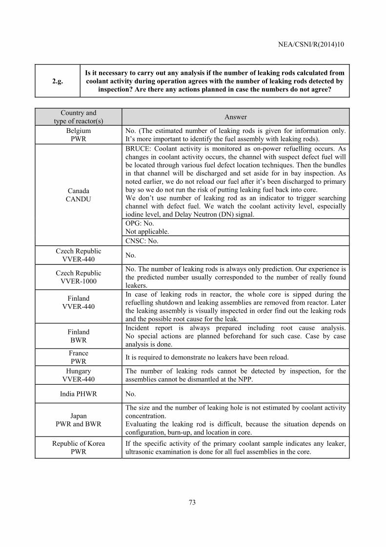
NEA/CSNI/R(2014)10
73
2.g. Is it necessary to carry out any analysis if the number of leaking rods calculated from coolant activity during operation agrees with the number of leaking rods detected by
inspection? Are there any actions planned in case the numbers do not agree?
Country and
type of reactor(s) Answer
Belgium PWR
No. (The estimated number of leaking rods is given for information only. It’s more important to identify the fuel assembly with leaking rods).
Canada CANDU
BRUCE: Coolant activity is monitored as on-power refuelling occurs. As changes in coolant activity occurs, the channel with suspect defect fuel will be located through various fuel defect location techniques. Then the bundles in that channel will be discharged and set aside for in bay inspection. As noted earlier, we do not reload our fuel after it’s been discharged to primary bay so we do not run the risk of putting leaking fuel back into core. We don’t use number of leaking rod as an indicator to trigger searching channel with defect fuel. We watch the coolant activity level, especially iodine level, and Delay Neutron (DN) signal. OPG: No. Not applicable. CNSC: No.
Czech Republic VVER-440 No.
Czech Republic VVER-1000
No. The number of leaking rods is always only prediction. Our experience is the predicted number usually corresponded to the number of really found leakers.
Finland VVER-440
In case of leaking rods in reactor, the whole core is sipped during the refuelling shutdown and leaking assemblies are removed from reactor. Later the leaking assembly is visually inspected in order find out the leaking rods and the possible root cause for the leak.
Finland BWR
Incident report is always prepared including root cause analysis.No special actions are planned beforehand for such case. Case by case analysis is done.
France PWR It is required to demonstrate no leakers have been reload.
Hungary VVER-440
The number of leaking rods cannot be detected by inspection, for the assemblies cannot be dismantled at the NPP.
India PHWR No.
Japan PWR and BWR
The size and the number of leaking hole is not estimated by coolant activity concentration. Evaluating the leaking rod is difficult, because the situation depends on configuration, burn-up, and location in core.
Republic of Korea PWR
If the specific activity of the primary coolant sample indicates any leaker, ultrasonic examination is done for all fuel assemblies in the core.
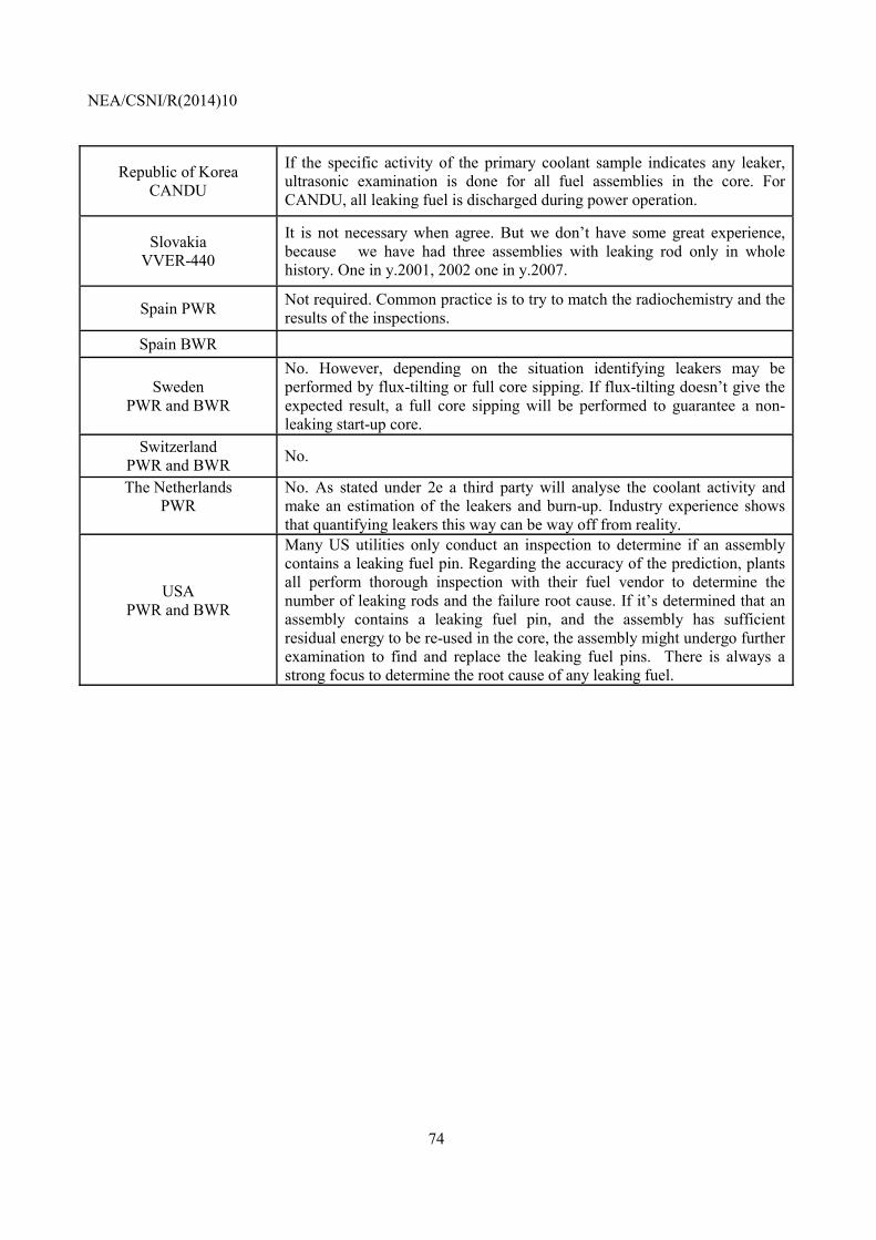
NEA/CSNI/R(2014)10
74
Republic of Korea CANDU
If the specific activity of the primary coolant sample indicates any leaker, ultrasonic examination is done for all fuel assemblies in the core. For CANDU, all leaking fuel is discharged during power operation.
Slovakia VVER-440
It is not necessary when agree. But we don’t have some great experience, because we have had three assemblies with leaking rod only in whole history. One in y.2001, 2002 one in y.2007.
Spain PWR Not required. Common practice is to try to match the radiochemistry and the results of the inspections.
Spain BWR
Sweden PWR and BWR
No. However, depending on the situation identifying leakers may be performed by flux-tilting or full core sipping. If flux-tilting doesn’t give the expected result, a full core sipping will be performed to guarantee a non-leaking start-up core.
Switzerland PWR and BWR No.
The Netherlands PWR
No. As stated under 2e a third party will analyse the coolant activity and make an estimation of the leakers and burn-up. Industry experience shows that quantifying leakers this way can be way off from reality.
USA PWR and BWR
Many US utilities only conduct an inspection to determine if an assembly contains a leaking fuel pin. Regarding the accuracy of the prediction, plants all perform thorough inspection with their fuel vendor to determine the number of leaking rods and the failure root cause. If it’s determined that an assembly contains a leaking fuel pin, and the assembly has sufficient residual energy to be re-used in the core, the assembly might undergo further examination to find and replace the leaking fuel pins. There is always a strong focus to determine the root cause of any leaking fuel.
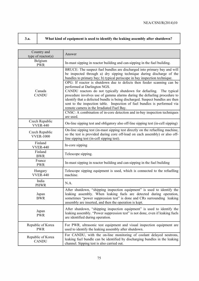
NEA/CSNI/R(2014)10
75
3.a. What kind of equipment is used to identify the leaking assembly after shutdown?
Country and
type of reactor(s) Answer
Belgium PWR In-mast sipping in reactor building and can-sipping in the fuel building.
Canada CANDU
BRUCE: The suspect fuel bundles are discharged into primary bay and will be inspected through a) dry sipping technique during discharge of the bundles to primary bay; b) typical periscope in bay inspection technique. OPG: If reactor is shutdown due to defects then feeder scanning can be performed at Darlington NGS. CANDU reactors do not typically shutdown for defueling. The typical procedure involves use of gamma alarms during the defueling procedure to identify that a defected bundle is being discharged. Suspect bundles are then sent to the inspection table. Inspection of fuel bundles is performed via remote camera in the Irradiated Fuel Bay. CNSC: A combination of in-core detection and in-bay inspection techniques are used.
Czech Republic VVER-440 On-line sipping test and obligatory also off-line sipping test (in-cell sipping)
Czech Republic VVER-1000
On-line sipping test (in-mast sipping test directly on the refuelling machine, so the test is provided during core off-load on each assembly) or also off-line sipping test (in-cell sipping test).
Finland VVER-440 In-core sipping
Finland BWR Telescope sipping.
France PWR In-mast sipping in reactor building and can-sipping in the fuel building
Hungary VVER-440
Telescope sipping equipment is used, which is connected to the refuelling machine.
India PHWR N.A.
Japan BWR
After shutdown, “shipping inspection equipment” is used to identify the leaking assembly. When leaking fuels are detected during operation, sometimes “power suppression test” is done and CRs surrounding leaking assembly are inserted, and then the operation is kept.
Japan PWR
After shutdown, “shipping inspection equipment” is used to identify the leaking assembly. “Power suppression test” is not done, even if leaking fuels are identified during operation.
Republic of Korea PWR
For PWR, ultrasonic test equipment and visual inspection equipment are used to identify the leaking assembly after shutdown.
Republic of Korea CANDU
For CANDU, with the on-line monitoring of coolant delayed neutrons, leaking fuel bundle can be identified by discharging bundles in the leaking channel. Sipping test is also carried out.
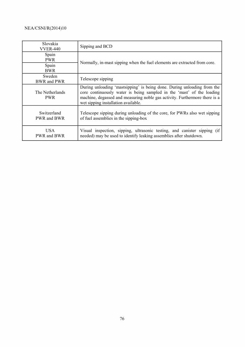
NEA/CSNI/R(2014)10
76
Slovakia VVER-440 Sipping and BCD
Spain PWR Normally, in-mast sipping when the fuel elements are extracted from core. Spain BWR
Sweden BWR and PWR Telescope sipping
The Netherlands PWR
During unloading ‘mastsipping’ is being done. During unloading from the core continuously water is being sampled in the ‘mast’ of the loading machine, degassed and measuring noble gas activity. Furthermore there is a wet sipping installation available.
Switzerland PWR and BWR
Telescope sipping during unloading of the core, for PWRs also wet sipping of fuel assemblies in the sipping-box
USA PWR and BWR
Visual inspection, sipping, ultrasonic testing, and canister sipping (if needed) may be used to identify leaking assemblies after shutdown.
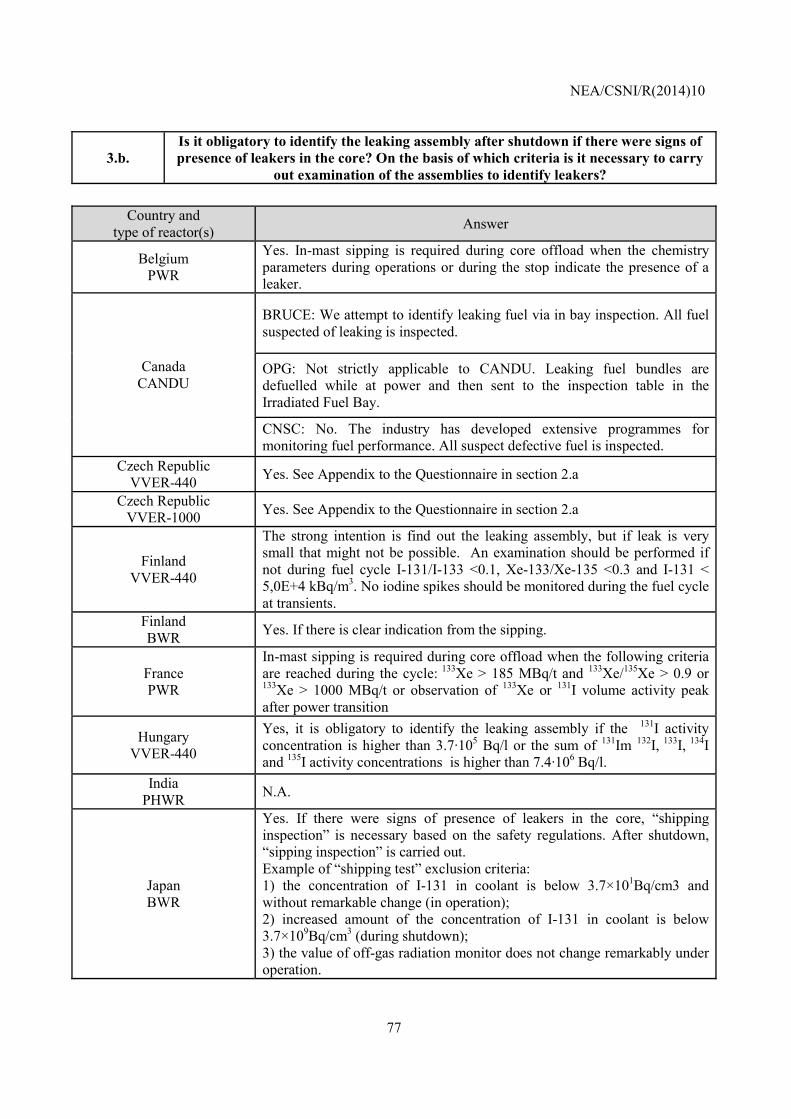
NEA/CSNI/R(2014)10
77
3.b. Is it obligatory to identify the leaking assembly after shutdown if there were signs of presence of leakers in the core? On the basis of which criteria is it necessary to carry
out examination of the assemblies to identify leakers?
Country and type of reactor(s) Answer
Belgium PWR
Yes. In-mast sipping is required during core offload when the chemistry parameters during operations or during the stop indicate the presence of a leaker.
Canada CANDU
BRUCE: We attempt to identify leaking fuel via in bay inspection. All fuel suspected of leaking is inspected.
OPG: Not strictly applicable to CANDU. Leaking fuel bundles are defuelled while at power and then sent to the inspection table in the Irradiated Fuel Bay.
CNSC: No. The industry has developed extensive programmes for monitoring fuel performance. All suspect defective fuel is inspected.
Czech Republic VVER-440 Yes. See Appendix to the Questionnaire in section 2.a
Czech Republic VVER-1000 Yes. See Appendix to the Questionnaire in section 2.a
Finland VVER-440
The strong intention is find out the leaking assembly, but if leak is very small that might not be possible. An examination should be performed if not during fuel cycle I-131/I-133 <0.1, Xe-133/Xe-135 <0.3 and I-131 < 5,0E+4 kBq/m3. No iodine spikes should be monitored during the fuel cycle at transients.
Finland BWR Yes. If there is clear indication from the sipping.
France PWR
In-mast sipping is required during core offload when the following criteria are reached during the cycle: 133Xe > 185 MBq/t and 133Xe/135Xe > 0.9 or 133Xe > 1000 MBq/t or observation of 133Xe or 131I volume activity peak after power transition
Hungary VVER-440
Yes, it is obligatory to identify the leaking assembly if the 131I activity concentration is higher than 3.7·105 Bq/l or the sum of 131Im 132I, 133I, 134I and 135I activity concentrations is higher than 7.4·106 Bq/l.
India PHWR N.A.
Japan BWR
Yes. If there were signs of presence of leakers in the core, “shipping inspection” is necessary based on the safety regulations. After shutdown, “sipping inspection” is carried out. Example of “shipping test” exclusion criteria: 1) the concentration of I-131 in coolant is below 3.7×101Bq/cm3 and without remarkable change (in operation); 2) increased amount of the concentration of I-131 in coolant is below 3.7×10⁹Bq/cm3 (during shutdown); 3) the value of off-gas radiation monitor does not change remarkably under operation.
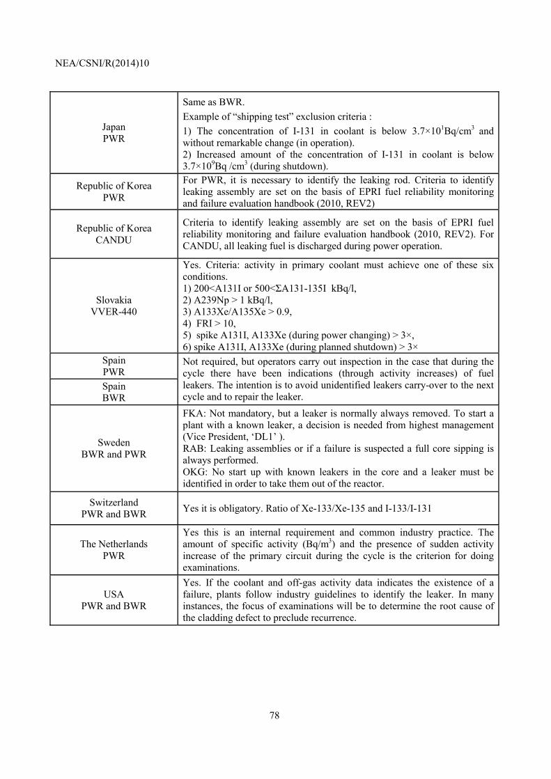
NEA/CSNI/R(2014)10
78
Japan PWR
Same as BWR. Example of “shipping test” exclusion criteria : 1) The concentration of I-131 in coolant is below 3.7×101Bq/cm3 and without remarkable change (in operation). 2) Increased amount of the concentration of I-131 in coolant is below 3.7×10⁹Bq /cm3 (during shutdown).
Republic of Korea PWR
For PWR, it is necessary to identify the leaking rod. Criteria to identify leaking assembly are set on the basis of EPRI fuel reliability monitoring and failure evaluation handbook (2010, REV2)
Republic of Korea CANDU
Criteria to identify leaking assembly are set on the basis of EPRI fuel reliability monitoring and failure evaluation handbook (2010, REV2). For CANDU, all leaking fuel is discharged during power operation.
Slovakia VVER-440
Yes. Criteria: activity in primary coolant must achieve one of these six conditions. 1) 200<A131I or 500<ΣA131-135I kBq/l, 2) A239Np > 1 kBq/l, 3) A133Xe/A135Xe > 0.9, 4) FRI > 10, 5) spike A131I, A133Xe (during power changing) > 3×, 6) spike A131I, A133Xe (during planned shutdown) > 3×
Spain PWR
Not required, but operators carry out inspection in the case that during the cycle there have been indications (through activity increases) of fuel leakers. The intention is to avoid unidentified leakers carry-over to the next cycle and to repair the leaker.
Spain BWR
Sweden BWR and PWR
FKA: Not mandatory, but a leaker is normally always removed. To start a plant with a known leaker, a decision is needed from highest management (Vice President, ‘DL1’ ). RAB: Leaking assemblies or if a failure is suspected a full core sipping is always performed. OKG: No start up with known leakers in the core and a leaker must be identified in order to take them out of the reactor.
Switzerland PWR and BWR Yes it is obligatory. Ratio of Xe-133/Xe-135 and I-133/I-131
The Netherlands PWR
Yes this is an internal requirement and common industry practice. The amount of specific activity (Bq/m3) and the presence of sudden activity increase of the primary circuit during the cycle is the criterion for doing examinations.
USA PWR and BWR
Yes. If the coolant and off-gas activity data indicates the existence of a failure, plants follow industry guidelines to identify the leaker. In many instances, the focus of examinations will be to determine the root cause of the cladding defect to preclude recurrence.
NEA/CSNI/R(2014)10
79
3.c. Is it necessary to identify the root cause in any cases of fuel failure?
Country and
type of reactor(s) Answer
Belgium PWR No, although it is desirable.
Canada CANDU
BRUCE: Yes. For the unknown cause of fuel defect, we generally conduct detail investigation, but sometimes the results are not conclusive.
OPG: No.
CNSC: No. Czech Republic
VVER-440 Best practice recommends to try to identify it
Czech Republic VVER-1000 If it is possible yes. Best practice recommends it
Finland VVER-440 This is a strong intention.
Finland BWR The goal is to find root cause; nevertheless it may remain unknown.
France PWR
Most of the time it is required to investigate the failure root cause. Nevertheless, if a generic failure root cause has been identified and if there is no, or little, doubt on the origin of the leak, only a limited number of leakers are examined
Hungary VVER-440
No, it is not necessary. There are no specific tools at the NPP to identify the cause or type of failure.
India PHWR As a good practice, it is done.
Japan BWR
The visual inspection and the fibre scope investigation will be performed on the fuel assembly in which a leakage was detected by the shipping inspection. The PIEs will be performed in case of a comparatively large scale or a special type of failure. The ordinary pin hole may not be investigated practically in detail at the hot laboratory, and not specified the cause in many cases.
Japan PWR
The PIEs will be performed in case of a comparatively large scale or a special type of failure. The ordinary pin hole may not be investigated practically in detail at the hot laboratory, and not specified the cause in many cases.
Republic of Korea PWR For both PWR and CANDU, if the cause of failure is not clear, hot cell
examination is carried out to find the root cause. Republic of Korea CANDU Slovakia
VVER-440 Yes.
Spain PWR Not required, in practice it depends of plants and vendors.
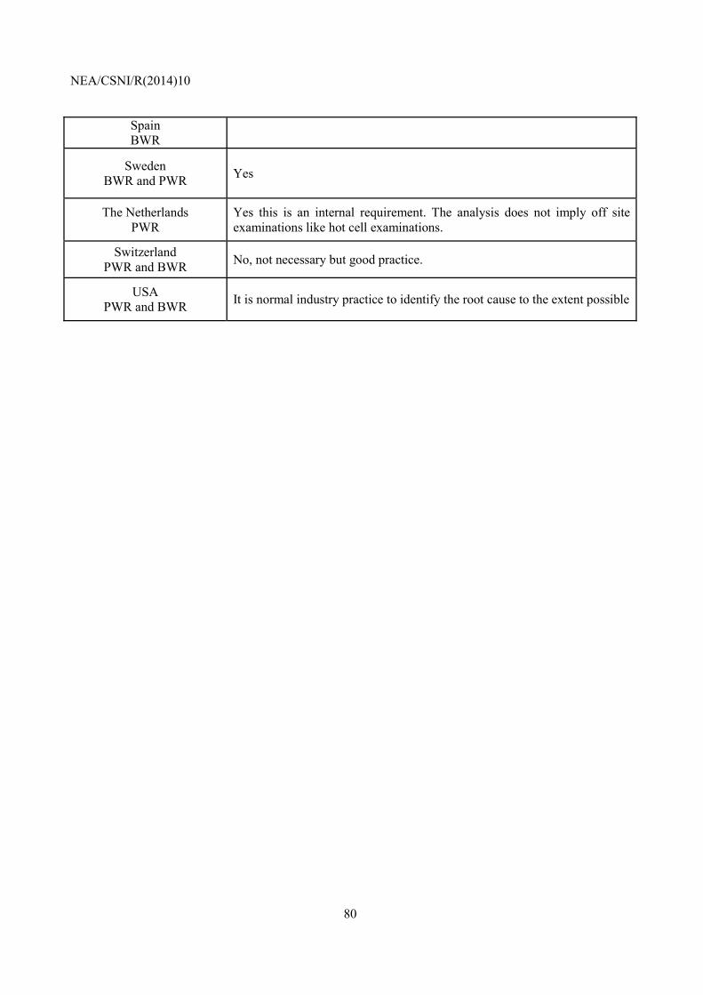
NEA/CSNI/R(2014)10
80
Spain BWR
Sweden BWR and PWR Yes
The Netherlands PWR
Yes this is an internal requirement. The analysis does not imply off site examinations like hot cell examinations.
Switzerland PWR and BWR No, not necessary but good practice.
USA PWR and BWR It is normal industry practice to identify the root cause to the extent possible
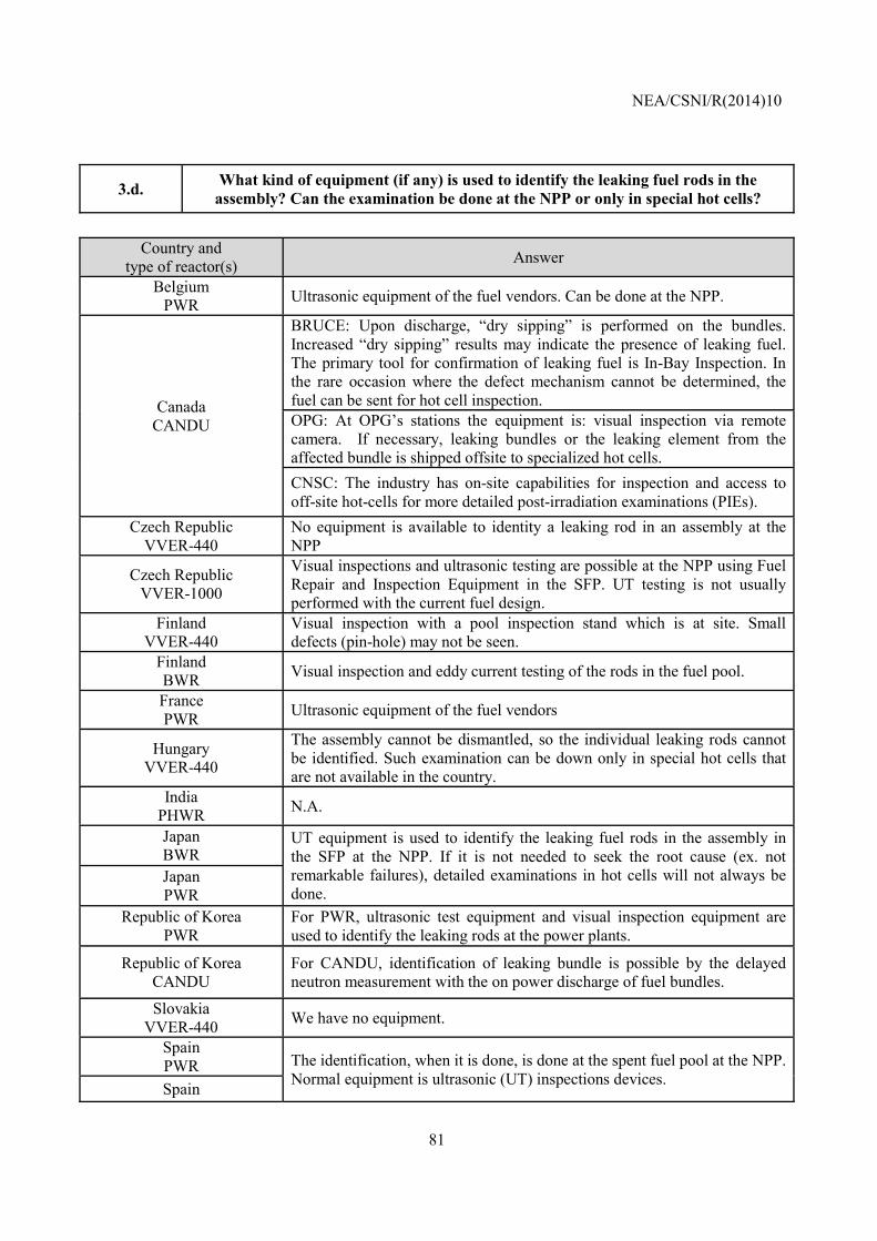
NEA/CSNI/R(2014)10
81
3.d. What kind of equipment (if any) is used to identify the leaking fuel rods in the assembly? Can the examination be done at the NPP or only in special hot cells?
Country and
type of reactor(s) Answer
Belgium PWR Ultrasonic equipment of the fuel vendors. Can be done at the NPP.
Canada CANDU
BRUCE: Upon discharge, “dry sipping” is performed on the bundles. Increased “dry sipping” results may indicate the presence of leaking fuel. The primary tool for confirmation of leaking fuel is In-Bay Inspection. In the rare occasion where the defect mechanism cannot be determined, the fuel can be sent for hot cell inspection. OPG: At OPG’s stations the equipment is: visual inspection via remote camera. If necessary, leaking bundles or the leaking element from the affected bundle is shipped offsite to specialized hot cells. CNSC: The industry has on-site capabilities for inspection and access to off-site hot-cells for more detailed post-irradiation examinations (PIEs).
Czech Republic VVER-440
No equipment is available to identity a leaking rod in an assembly at the NPP
Czech Republic VVER-1000
Visual inspections and ultrasonic testing are possible at the NPP using Fuel Repair and Inspection Equipment in the SFP. UT testing is not usually performed with the current fuel design.
Finland VVER-440
Visual inspection with a pool inspection stand which is at site. Small defects (pin-hole) may not be seen.
Finland BWR Visual inspection and eddy current testing of the rods in the fuel pool.
France PWR Ultrasonic equipment of the fuel vendors
Hungary VVER-440
The assembly cannot be dismantled, so the individual leaking rods cannot be identified. Such examination can be down only in special hot cells that are not available in the country.
India PHWR N.A.
Japan BWR
UT equipment is used to identify the leaking fuel rods in the assembly in the SFP at the NPP. If it is not needed to seek the root cause (ex. not remarkable failures), detailed examinations in hot cells will not always be done.
Japan PWR
Republic of Korea PWR
For PWR, ultrasonic test equipment and visual inspection equipment are used to identify the leaking rods at the power plants.
Republic of Korea CANDU
For CANDU, identification of leaking bundle is possible by the delayed neutron measurement with the on power discharge of fuel bundles.
Slovakia VVER-440 We have no equipment.
Spain PWR The identification, when it is done, is done at the spent fuel pool at the NPP.
Normal equipment is ultrasonic (UT) inspections devices. Spain
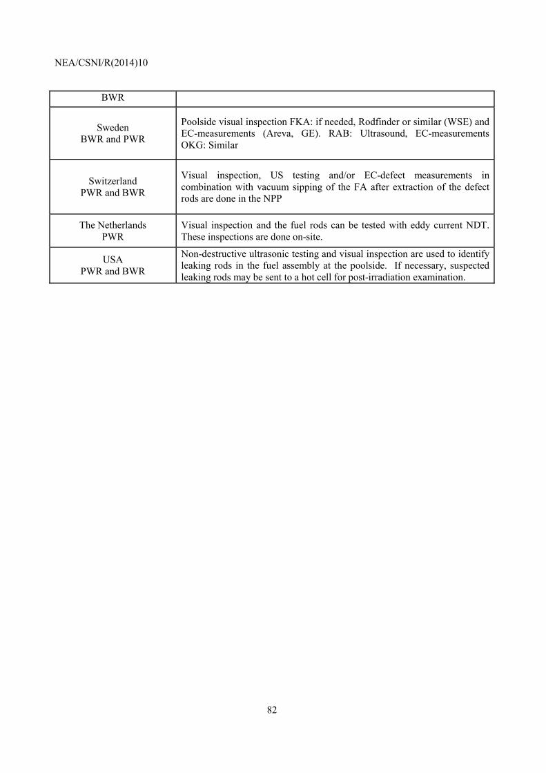
NEA/CSNI/R(2014)10
82
BWR
Sweden BWR and PWR
Poolside visual inspection FKA: if needed, Rodfinder or similar (WSE) and EC-measurements (Areva, GE). RAB: Ultrasound, EC-measurements OKG: Similar
Switzerland PWR and BWR
Visual inspection, US testing and/or EC-defect measurements in combination with vacuum sipping of the FA after extraction of the defect rods are done in the NPP
The Netherlands PWR
Visual inspection and the fuel rods can be tested with eddy current NDT. These inspections are done on-site.
USA PWR and BWR
Non-destructive ultrasonic testing and visual inspection are used to identify leaking rods in the fuel assembly at the poolside. If necessary, suspected leaking rods may be sent to a hot cell for post-irradiation examination.
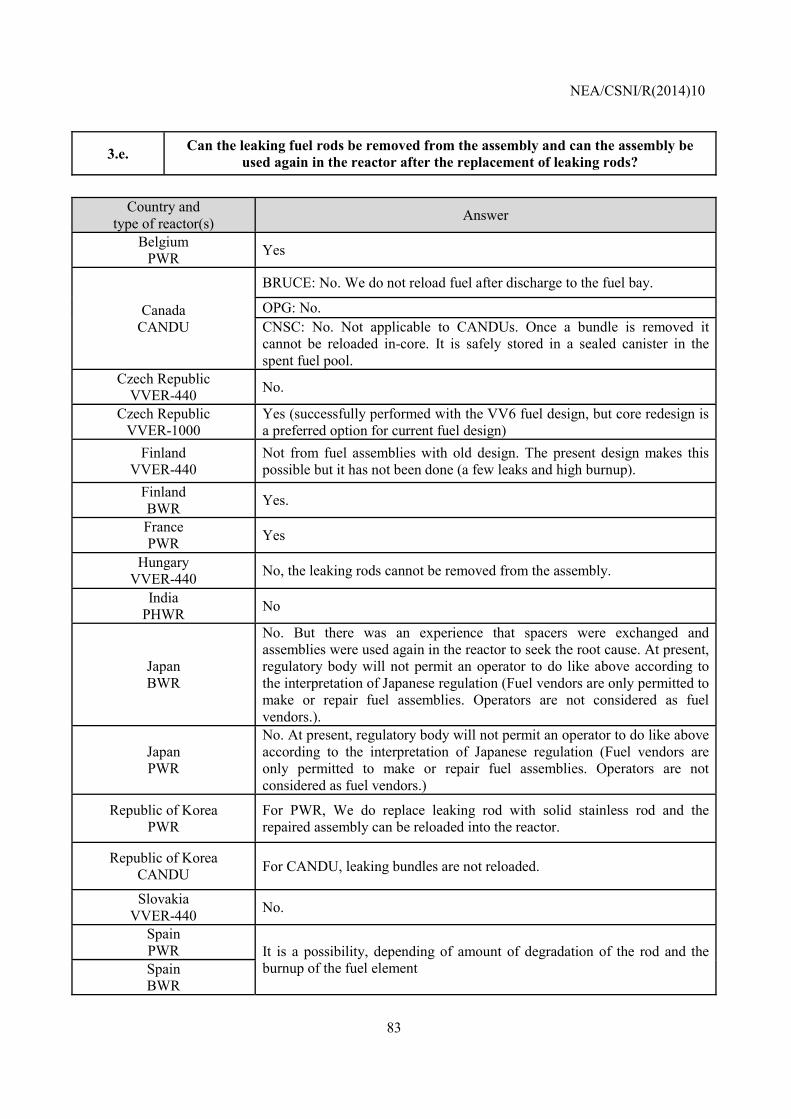
NEA/CSNI/R(2014)10
83
3.e. Can the leaking fuel rods be removed from the assembly and can the assembly be used again in the reactor after the replacement of leaking rods?
Country and
type of reactor(s) Answer
Belgium PWR Yes
Canada CANDU
BRUCE: No. We do not reload fuel after discharge to the fuel bay.
OPG: No. CNSC: No. Not applicable to CANDUs. Once a bundle is removed it cannot be reloaded in-core. It is safely stored in a sealed canister in the spent fuel pool.
Czech Republic VVER-440 No.
Czech Republic VVER-1000
Yes (successfully performed with the VV6 fuel design, but core redesign is a preferred option for current fuel design)
Finland VVER-440
Not from fuel assemblies with old design. The present design makes this possible but it has not been done (a few leaks and high burnup).
Finland BWR Yes.
France PWR Yes
Hungary VVER-440 No, the leaking rods cannot be removed from the assembly.
India PHWR No
Japan BWR
No. But there was an experience that spacers were exchanged and assemblies were used again in the reactor to seek the root cause. At present, regulatory body will not permit an operator to do like above according to the interpretation of Japanese regulation (Fuel vendors are only permitted to make or repair fuel assemblies. Operators are not considered as fuel vendors.).
Japan PWR
No. At present, regulatory body will not permit an operator to do like above according to the interpretation of Japanese regulation (Fuel vendors are only permitted to make or repair fuel assemblies. Operators are not considered as fuel vendors.)
Republic of Korea PWR
For PWR, We do replace leaking rod with solid stainless rod and the repaired assembly can be reloaded into the reactor.
Republic of Korea CANDU For CANDU, leaking bundles are not reloaded.
Slovakia VVER-440 No.
Spain PWR It is a possibility, depending of amount of degradation of the rod and the
burnup of the fuel element Spain BWR
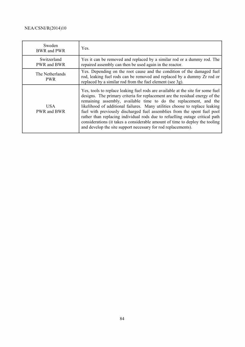
NEA/CSNI/R(2014)10
84
Sweden BWR and PWR Yes.
Switzerland PWR and BWR
Yes it can be removed and replaced by a similar rod or a dummy rod. The repaired assembly can then be used again in the reactor.
The Netherlands PWR
Yes. Depending on the root cause and the condition of the damaged fuel rod, leaking fuel rods can be removed and replaced by a dummy Zr rod or replaced by a similar rod from the fuel element (see 3g).
USA PWR and BWR
Yes, tools to replace leaking fuel rods are available at the site for some fuel designs. The primary criteria for replacement are the residual energy of the remaining assembly, available time to do the replacement, and the likelihood of additional failures. Many utilities choose to replace leaking fuel with previously discharged fuel assemblies from the spent fuel pool rather than replacing individual rods due to refuelling outage critical path considerations (it takes a considerable amount of time to deploy the tooling and develop the site support necessary for rod replacements).
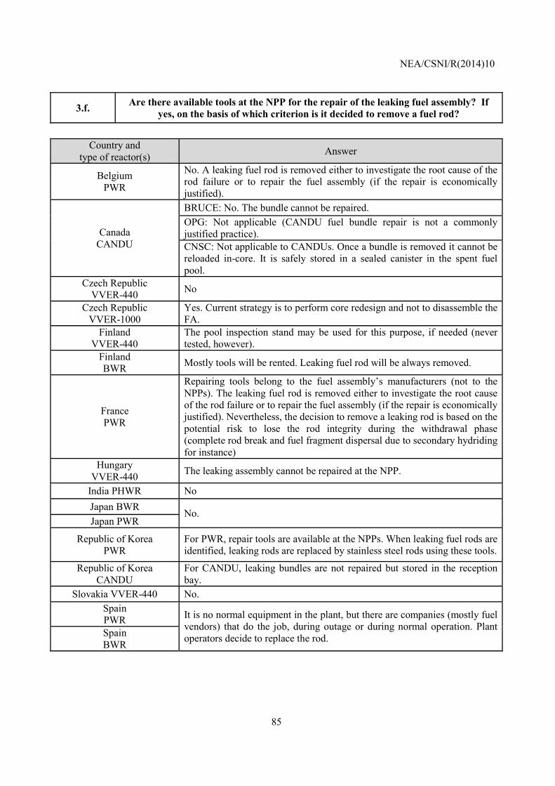
NEA/CSNI/R(2014)10
85
3.f. Are there available tools at the NPP for the repair of the leaking fuel assembly? If yes, on the basis of which criterion is it decided to remove a fuel rod?
Country and
type of reactor(s) Answer
Belgium PWR
No. A leaking fuel rod is removed either to investigate the root cause of the rod failure or to repair the fuel assembly (if the repair is economically justified).
Canada CANDU
BRUCE: No. The bundle cannot be repaired. OPG: Not applicable (CANDU fuel bundle repair is not a commonly justified practice). CNSC: Not applicable to CANDUs. Once a bundle is removed it cannot be reloaded in-core. It is safely stored in a sealed canister in the spent fuel pool.
Czech Republic VVER-440 No
Czech Republic VVER-1000
Yes. Current strategy is to perform core redesign and not to disassemble the FA.
Finland VVER-440
The pool inspection stand may be used for this purpose, if needed (never tested, however).
Finland BWR Mostly tools will be rented. Leaking fuel rod will be always removed.
France PWR
Repairing tools belong to the fuel assembly’s manufacturers (not to the NPPs). The leaking fuel rod is removed either to investigate the root cause of the rod failure or to repair the fuel assembly (if the repair is economically justified). Nevertheless, the decision to remove a leaking rod is based on the potential risk to lose the rod integrity during the withdrawal phase (complete rod break and fuel fragment dispersal due to secondary hydriding for instance)
Hungary VVER-440 The leaking assembly cannot be repaired at the NPP.
India PHWR No Japan BWR No. Japan PWR
Republic of Korea PWR
For PWR, repair tools are available at the NPPs. When leaking fuel rods are identified, leaking rods are replaced by stainless steel rods using these tools.
Republic of Korea CANDU
For CANDU, leaking bundles are not repaired but stored in the reception bay.
Slovakia VVER-440 No. Spain PWR It is no normal equipment in the plant, but there are companies (mostly fuel
vendors) that do the job, during outage or during normal operation. Plant operators decide to replace the rod. Spain
BWR
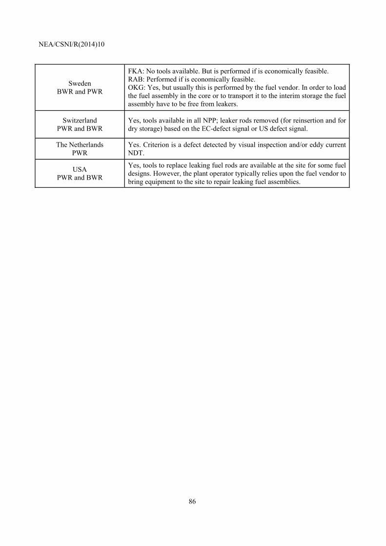
NEA/CSNI/R(2014)10
86
Sweden BWR and PWR
FKA: No tools available. But is performed if is economically feasible. RAB: Performed if is economically feasible. OKG: Yes, but usually this is performed by the fuel vendor. In order to load the fuel assembly in the core or to transport it to the interim storage the fuel assembly have to be free from leakers.
Switzerland PWR and BWR
Yes, tools available in all NPP; leaker rods removed (for reinsertion and for dry storage) based on the EC-defect signal or US defect signal.
The Netherlands PWR
Yes. Criterion is a defect detected by visual inspection and/or eddy current NDT.
USA PWR and BWR
Yes, tools to replace leaking fuel rods are available at the site for some fuel designs. However, the plant operator typically relies upon the fuel vendor to bring equipment to the site to repair leaking fuel assemblies.
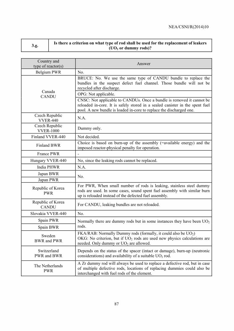
NEA/CSNI/R(2014)10
87
3.g. Is there a criterion on what type of rod shall be used for the replacement of leakers (UO2 or dummy rods)?
Country and
type of reactor(s) Answer
Belgium PWR No.
Canada CANDU
BRUCE: No. We use the same type of CANDU bundle to replace the bundles in the suspect defect fuel channel. Those bundle will not be recycled after discharge. OPG: Not applicable. CNSC: Not applicable to CANDUs. Once a bundle is removed it cannot be reloaded in-core. It is safely stored in a sealed canister in the spent fuel pool. A new bundle is loaded in-core to replace the discharged one.
Czech Republic VVER-440 N.A.
Czech Republic VVER-1000 Dummy only.
Finland VVER-440 Not decided.
Finland BWR Choice is based on burn-up of the assembly (=available energy) and the imposed reactor-physical penalty for operation.
France PWR - Hungary VVER-440 No, since the leaking rods cannot be replaced.
India PHWR N.A. Japan BWR No. Japan PWR
Republic of Korea PWR
For PWR, When small number of rods is leaking, stainless steel dummy rods are used. In some cases, sound spent fuel assembly with similar burn up is reloaded instead of the defected fuel assembly.
Republic of Korea CANDU For CANDU, leaking bundles are not reloaded.
Slovakia VVER-440 No. Spain PWR Normally there are dummy rods but in some instances they have been UO2
rods. Spain BWR
Sweden BWR and PWR
FKA/RAB: Normally Dummy rods (formally, it could also be UO2) OKG: No criterion, but if UO2 rods are used new physics calculations are needed. Only dummy or UO2 are allowed.
Switzerland PWR and BWR
Depends on the status of the spacer (intact or damage), burn-up (neutronic considerations) and availability of a suitable UO2 rod.
The Netherlands PWR
A Zr dummy rod will always be used to replace a defective rod, but in case of multiple defective rods, locations of replacing dummies could also be interchanged with fuel rods of the element.
NEA/CSNI/R(2014)10
88
USA PWR and BWR
If used, a replacement rod is usually a dummy rod (solid stainless steel) or a used rod. The type of rod and the number of rods that can be replaced in each assembly may be dependent upon Technical Specifications or other operational limits. There are no criteria beyond those normally imposed on fuel rods.
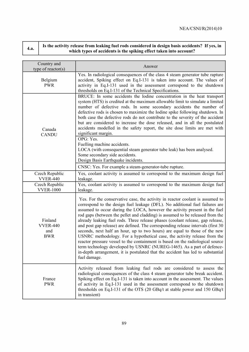
NEA/CSNI/R(2014)10
89
4.a. Is the activity release from leaking fuel rods considered in design basis accidents? If yes, in which types of accidents is the spiking effect taken into account?
Country and
type of reactor(s) Answer
Belgium PWR
Yes. In radiological consequences of the class 4 steam generator tube rapture accident, Spiking effect on Eq.I-131 is taken into account. The values of activity in Eq.I-131 used in the assessment correspond to the shutdown thresholds on Eq.I-131 of the Technical Specifications.
Canada CANDU
BRUCE: In some accidents the Iodine concentration in the heat transport system (HTS) is credited at the maximum allowable limit to simulate a limited number of defective rods. In some secondary accidents the number of defective rods is chosen to maximize the Iodine spike following shutdown. In both case the defective rods do not contribute to the severity of the accident but are considered to increase the dose released, and in all the postulated accidents modelled in the safety report, the site dose limits are met with significant margin. OPG: Yes. Fuelling machine accidents. LOCA (with consequential steam generator tube leak) has been analysed. Some secondary side accidents. Design Basis Earthquake incidents. CNSC: Yes. For example a steam-generator-tube rupture.
Czech Republic VVER-440
Yes, coolant activity is assumed to correspond to the maximum design fuel leakage.
Czech Republic VVER-1000
Yes, coolant activity is assumed to correspond to the maximum design fuel leakage.
Finland VVER-440
and BWR
Yes. For the conservative case, the activity in reactor coolant is assumed to correspond to the design fuel leakage (DFL). No additional fuel failures are assumed to occur during the LOCA, however the activity present in the fuel rod gaps (between the pellet and cladding) is assumed to be released from the already leaking fuel rods. Three release phases (coolant release, gap release, and post gap release) are defined. The corresponding release intervals (first 30 seconds, next half an hour, up to two hours) are equal to those of the new USNRC methodology. For a hypothetical case, the activity release from the reactor pressure vessel to the containment is based on the radiological source term technology developed by USNRC (NUREG-1465). As a part of defence-in-depth arrangement, it is postulated that the accident has led to substantial fuel damage.
France PWR
Activity released from leaking fuel rods are considered to assess the radiological consequences of the class 4 steam generator tube break accident. Spiking effect on Eq.I-131 is taken into account in the assessment. The values of activity in Eq.I-131 used in the assessment correspond to the shutdown thresholds on Eq.I-131 of the OTS (20 GBq/t at stable power and 150 GBq/t in transient)
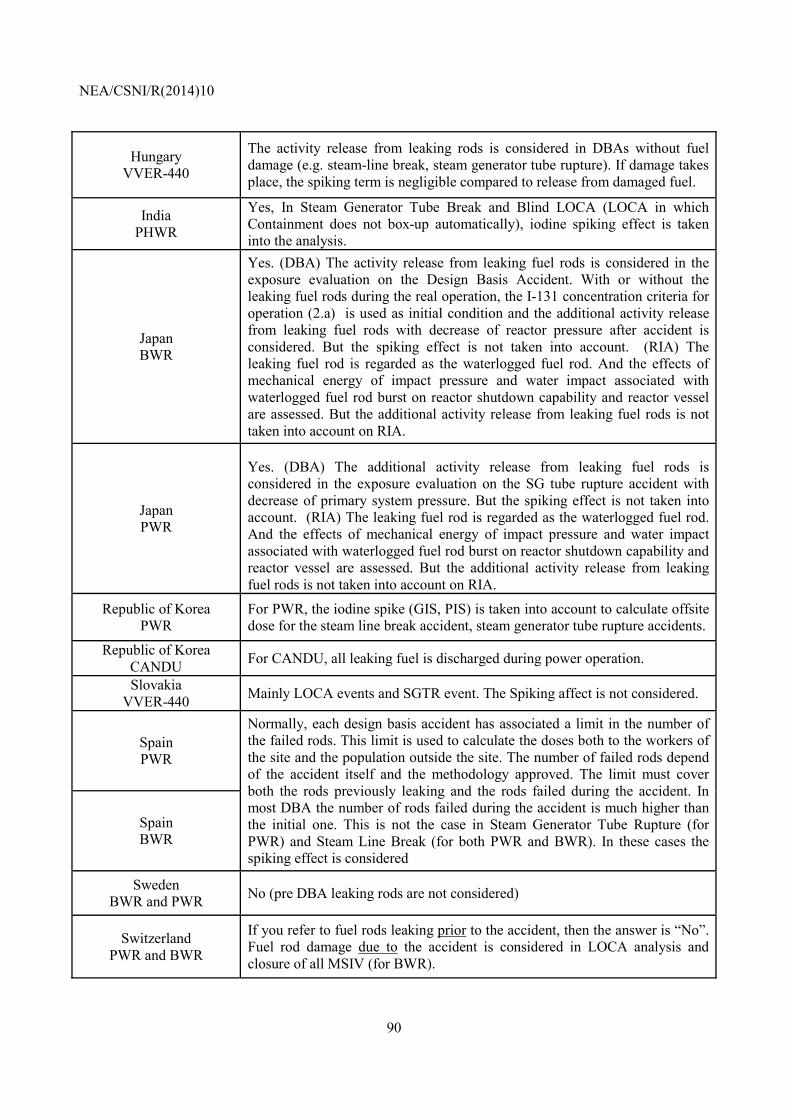
NEA/CSNI/R(2014)10
90
Hungary VVER-440
The activity release from leaking rods is considered in DBAs without fuel damage (e.g. steam-line break, steam generator tube rupture). If damage takes place, the spiking term is negligible compared to release from damaged fuel.
India PHWR
Yes, In Steam Generator Tube Break and Blind LOCA (LOCA in which Containment does not box-up automatically), iodine spiking effect is taken into the analysis.
Japan BWR
Yes. (DBA) The activity release from leaking fuel rods is considered in the exposure evaluation on the Design Basis Accident. With or without the leaking fuel rods during the real operation, the I-131 concentration criteria for operation (2.a) is used as initial condition and the additional activity release from leaking fuel rods with decrease of reactor pressure after accident is considered. But the spiking effect is not taken into account. (RIA) The leaking fuel rod is regarded as the waterlogged fuel rod. And the effects of mechanical energy of impact pressure and water impact associated with waterlogged fuel rod burst on reactor shutdown capability and reactor vessel are assessed. But the additional activity release from leaking fuel rods is not taken into account on RIA.
Japan PWR
Yes. (DBA) The additional activity release from leaking fuel rods is considered in the exposure evaluation on the SG tube rupture accident with decrease of primary system pressure. But the spiking effect is not taken into account. (RIA) The leaking fuel rod is regarded as the waterlogged fuel rod. And the effects of mechanical energy of impact pressure and water impact associated with waterlogged fuel rod burst on reactor shutdown capability and reactor vessel are assessed. But the additional activity release from leaking fuel rods is not taken into account on RIA.
Republic of Korea PWR
For PWR, the iodine spike (GIS, PIS) is taken into account to calculate offsite dose for the steam line break accident, steam generator tube rupture accidents.
Republic of Korea CANDU For CANDU, all leaking fuel is discharged during power operation.
Slovakia VVER-440 Mainly LOCA events and SGTR event. The Spiking affect is not considered.
Spain PWR
Normally, each design basis accident has associated a limit in the number of the failed rods. This limit is used to calculate the doses both to the workers of the site and the population outside the site. The number of failed rods depend of the accident itself and the methodology approved. The limit must cover both the rods previously leaking and the rods failed during the accident. In most DBA the number of rods failed during the accident is much higher than the initial one. This is not the case in Steam Generator Tube Rupture (for PWR) and Steam Line Break (for both PWR and BWR). In these cases the spiking effect is considered
Spain BWR
Sweden BWR and PWR No (pre DBA leaking rods are not considered)
Switzerland PWR and BWR
If you refer to fuel rods leaking prior to the accident, then the answer is “No”. Fuel rod damage due to the accident is considered in LOCA analysis and closure of all MSIV (for BWR).
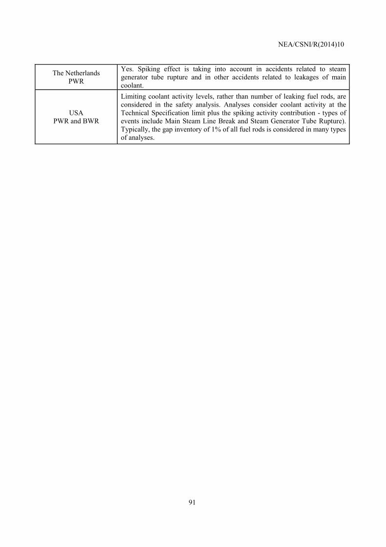
NEA/CSNI/R(2014)10
91
The Netherlands PWR
Yes. Spiking effect is taking into account in accidents related to steam generator tube rupture and in other accidents related to leakages of main coolant.
USA PWR and BWR
Limiting coolant activity levels, rather than number of leaking fuel rods, are considered in the safety analysis. Analyses consider coolant activity at the Technical Specification limit plus the spiking activity contribution - types of events include Main Steam Line Break and Steam Generator Tube Rupture). Typically, the gap inventory of 1% of all fuel rods is considered in many types of analyses.
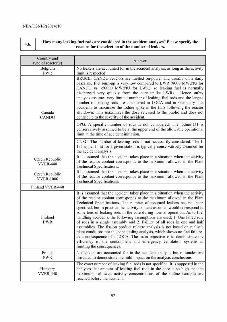
NEA/CSNI/R(2014)10
92
4.b. How many leaking fuel rods are considered in the accident analyses? Please specify the reasons for the selection of the number of leakers.
Country and
type of reactor(s) Answer
Belgium PWR
No leakers are accounted for in the accident analysis, as long as the activity limit is respected.
Canada CANDU
BRUCE: CANDU reactors are fuelled on-power and usually on a daily basis and fuel burn-up is very low compared to LWR (8000 MWd/tU for CANDU vs ~50000 MWd/tU for LWR), so leaking fuel is normally discharged very quickly from the core unlike LWRs. Hence safety analysis assumes very limited number of leaking fuel rods and the largest number of leaking rods are considered in LOCA and in secondary side accidents to maximize the Iodine spike in the HTS following the reactor shutdown. This maximizes the dose released to the public and does not contribute to the severity of the accident.
OPG: A specific number of rods is not considered. The iodine-131 is conservatively assumed to be at the upper end of the allowable operational limit at the time of accident initiation.
CNSC: The number of leaking rods is not necessarily considered. The I-131 upper limit for a given station is typically conservatively assumed for the accident analysis.
Czech Republic VVER-440
It is assumed that the accident takes place in a situation when the activity of the reactor coolant corresponds to the maximum allowed in the Plant Technical Specifications.
Czech Republic VVER-1000
It is assumed that the accident takes place in a situation when the activity of the reactor coolant corresponds to the maximum allowed in the Plant Technical Specifications.
Finland VVER-440
Finland BWR
It is assumed that the accident takes place in a situation when the activity of the reactor coolant corresponds to the maximum allowed in the Plant Technical Specifications. The number of assumed leakers has not been specified, but in practice the activity content assumed would correspond to some tens of leaking rods in the core during normal operation. As to fuel handling accidents, the following assumptions are used: 1. One failed row of rods in a single assembly and 2. Failure of all rods in one and half assemblies. The fission product release analysis is not based on realistic plant conditions nor the core cooling analysis, which shows no fuel failures as a consequence of a LOCA. The main objective is to demonstrate the efficiency of the containment and emergency ventilation systems in limiting the consequences.
France PWR
No leakers are accounted for in the accident analysis but rationales are provided to demonstrate the mild impact on the analysis conclusions
Hungary VVER-440
The exact number of leaking fuel rods is not specified. It is supposed in the analyses that amount of leaking fuel rods in the core is so high that the maximum allowed activity concentrations of the iodine isotopes are reached before the accident.
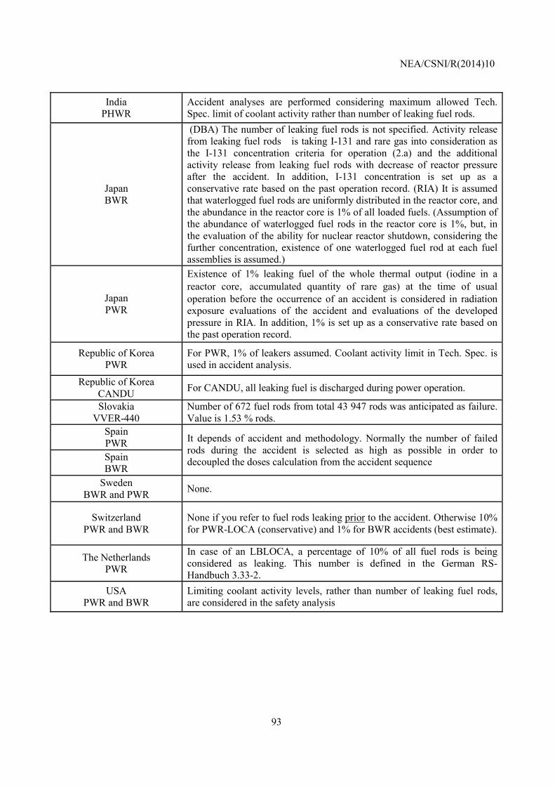
NEA/CSNI/R(2014)10
93
India PHWR
Accident analyses are performed considering maximum allowed Tech. Spec. limit of coolant activity rather than number of leaking fuel rods.
Japan BWR
(DBA) The number of leaking fuel rods is not specified. Activity release from leaking fuel rods is taking I-131 and rare gas into consideration as the I-131 concentration criteria for operation (2.a) and the additional activity release from leaking fuel rods with decrease of reactor pressure after the accident. In addition, I-131 concentration is set up as a conservative rate based on the past operation record. (RIA) It is assumed that waterlogged fuel rods are uniformly distributed in the reactor core, and the abundance in the reactor core is 1% of all loaded fuels. (Assumption of the abundance of waterlogged fuel rods in the reactor core is 1%, but, in the evaluation of the ability for nuclear reactor shutdown, considering the further concentration, existence of one waterlogged fuel rod at each fuel assemblies is assumed.)
Japan PWR
Existence of 1% leaking fuel of the whole thermal output (iodine in a reactor core,accumulated quantity of rare gas) at the time of usual operation before the occurrence of an accident is considered in radiation exposure evaluations of the accident and evaluations of the developed pressure in RIA. In addition, 1% is set up as a conservative rate based on the past operation record.
Republic of Korea PWR
For PWR, 1% of leakers assumed. Coolant activity limit in Tech. Spec. is used in accident analysis.
Republic of Korea CANDU For CANDU, all leaking fuel is discharged during power operation.
Slovakia VVER-440
Number of 672 fuel rods from total 43 947 rods was anticipated as failure. Value is 1.53 % rods.
Spain PWR It depends of accident and methodology. Normally the number of failed
rods during the accident is selected as high as possible in order to decoupled the doses calculation from the accident sequence Spain
BWR Sweden
BWR and PWR None.
Switzerland PWR and BWR
None if you refer to fuel rods leaking prior to the accident. Otherwise 10% for PWR-LOCA (conservative) and 1% for BWR accidents (best estimate).
The Netherlands PWR
In case of an LBLOCA, a percentage of 10% of all fuel rods is being considered as leaking. This number is defined in the German RS-Handbuch 3.33-2.
USA PWR and BWR
Limiting coolant activity levels, rather than number of leaking fuel rods, are considered in the safety analysis
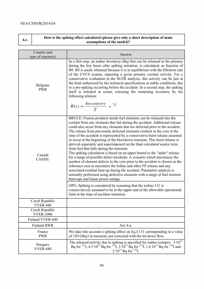
NEA/CSNI/R(2014)10
94
4.c. How is the spiking effect calculated (please give only a short description of main assumptions of the model)?
Country and
type of reactor(s) Answer
Belgium PWR
In a first step, an iodine Inventory (Bq) that can be released in the primary during the few hours after spiking initiation, is calculated, as function of R0. R0 is easily obtained because it is in equilibrium with the filtration rate of the CVCS system, imposing a given primary coolant activity. For a conservative evaluation in the SGTR analysis, this activity can be just at the limit authorized by the technical specifications at stable conditions, due to a pre-spiking occurring before the accident. In a second step, the spiking itself is initiated at scram, releasing the remaining inventory by the following relation:
Canada CANDU
BRUCE: Fission products inside fuel elements can be released into the coolant from any elements that fail during the accident. Additional release could also occur from any elements that are defected prior to the accident. The release from previously defected elements resident in the core at the time of the accident is represented by a conservative burst release assumed to occur at the beginning of the blowdown transient. This burst release is derived separately and superimposed on the final calculated source term from fuel that fails during the transient. The spiking calculation is based on an upper bound to the "spike" release for a range of possible defect incidents. A scenario which maximizes the number of element defects in the core prior to the accident is chosen as the reference case to maximize the Iodine and other FP release and any associated residual heat-up during the accident. Parametric analysis is normally performed using defective elements with a range of fuel element burn-ups and linear power ratings.
OPG: Spiking is considered by assuming that the iodine-131 is conservatively assumed to be at the upper end of the allowable operational limit at the time of accident initiation.
Czech Republic VVER-440
Czech Republic VVER-1000
Finland VVER-440 Finland BWR See 4.a.
France PWR
We take into account a spiking effect on Eq.I-131 corresponding to a value of 150 GBq/t in transient, not corrected with the let-down flow.
Hungary VVER-440
The released activity due to spiking is specified for iodine isotopes: 3·1013 Bq for 131I, 4.3·1013 Bq for 132I, 3·1013 Bq for 133I, 1.6·1013 Bq for 134I and
2·1013 Bq for 135I.
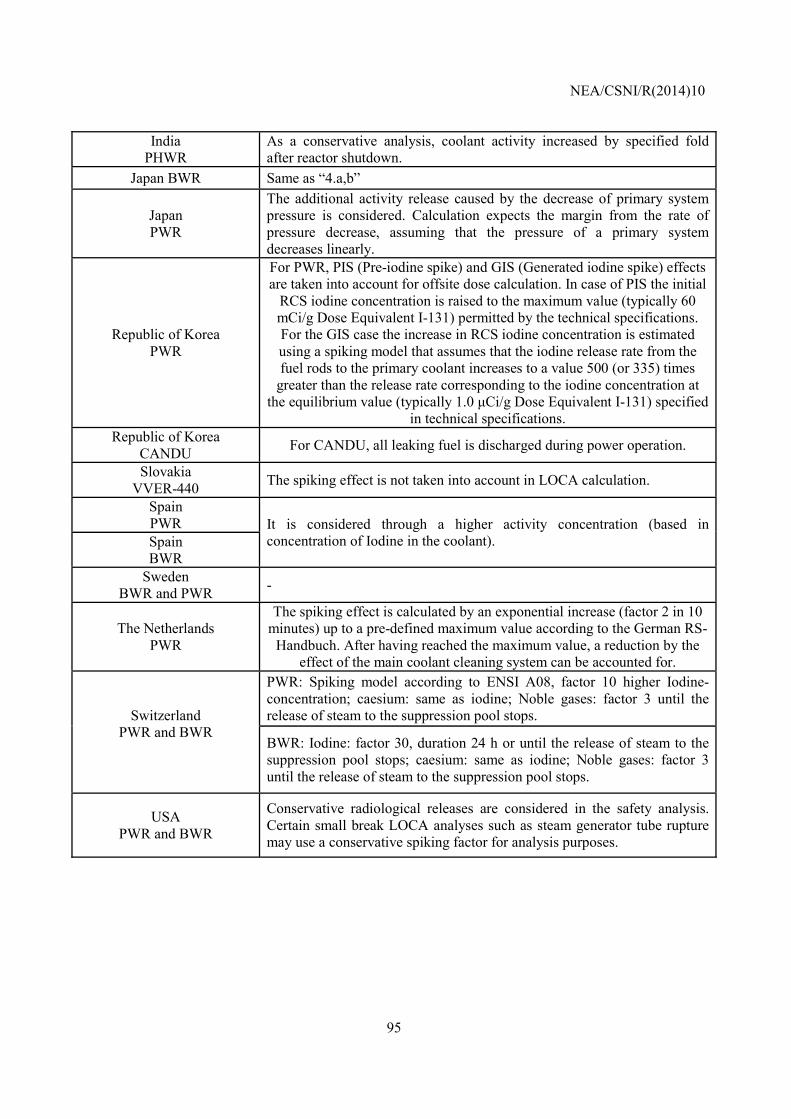
NEA/CSNI/R(2014)10
95
India PHWR
As a conservative analysis, coolant activity increased by specified fold after reactor shutdown.
Japan BWR Same as “4.a,b”
Japan PWR
The additional activity release caused by the decrease of primary system pressure is considered. Calculation expects the margin from the rate of pressure decrease, assuming that the pressure of a primary system decreases linearly.
Republic of Korea PWR
For PWR, PIS (Pre-iodine spike) and GIS (Generated iodine spike) effects are taken into account for offsite dose calculation. In case of PIS the initial
RCS iodine concentration is raised to the maximum value (typically 60 mCi/g Dose Equivalent I-131) permitted by the technical specifications. For the GIS case the increase in RCS iodine concentration is estimated using a spiking model that assumes that the iodine release rate from the fuel rods to the primary coolant increases to a value 500 (or 335) times
greater than the release rate corresponding to the iodine concentration at the equilibrium value (typically 1.0 µCi/g Dose Equivalent I-131) specified
in technical specifications. Republic of Korea
CANDU For CANDU, all leaking fuel is discharged during power operation.
Slovakia VVER-440 The spiking effect is not taken into account in LOCA calculation.
Spain PWR It is considered through a higher activity concentration (based in
concentration of Iodine in the coolant). Spain BWR
Sweden BWR and PWR -
The Netherlands PWR
The spiking effect is calculated by an exponential increase (factor 2 in 10 minutes) up to a pre-defined maximum value according to the German RS-
Handbuch. After having reached the maximum value, a reduction by the effect of the main coolant cleaning system can be accounted for.
Switzerland PWR and BWR
PWR: Spiking model according to ENSI A08, factor 10 higher Iodine-concentration; caesium: same as iodine; Noble gases: factor 3 until the release of steam to the suppression pool stops.
BWR: Iodine: factor 30, duration 24 h or until the release of steam to the suppression pool stops; caesium: same as iodine; Noble gases: factor 3 until the release of steam to the suppression pool stops.
USA PWR and BWR
Conservative radiological releases are considered in the safety analysis. Certain small break LOCA analyses such as steam generator tube rupture may use a conservative spiking factor for analysis purposes.
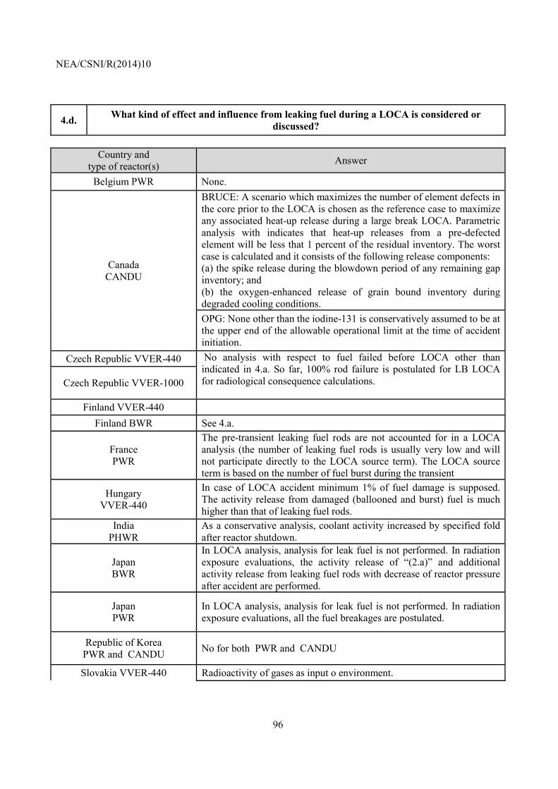
NEA/CSNI/R(2014)10
96
4.d. What kind of effect and influence from leaking fuel during a LOCA is considered or discussed?
Country and
type of reactor(s) Answer
Belgium PWR None.
Canada CANDU
BRUCE: A scenario which maximizes the number of element defects in the core prior to the LOCA is chosen as the reference case to maximize any associated heat-up release during a large break LOCA. Parametric analysis with indicates that heat-up releases from a pre-defected element will be less that 1 percent of the residual inventory. The worst case is calculated and it consists of the following release components: (a) the spike release during the blowdown period of any remaining gap inventory; and (b) the oxygen-enhanced release of grain bound inventory during degraded cooling conditions. OPG: None other than the iodine-131 is conservatively assumed to be at the upper end of the allowable operational limit at the time of accident initiation.
Czech Republic VVER-440 No analysis with respect to fuel failed before LOCA other than indicated in 4.a. So far, 100% rod failure is postulated for LB LOCA for radiological consequence calculations.
Czech Republic VVER-1000
Finland VVER-440 Finland BWR See 4.a.
France PWR
The pre-transient leaking fuel rods are not accounted for in a LOCA analysis (the number of leaking fuel rods is usually very low and will not participate directly to the LOCA source term). The LOCA source term is based on the number of fuel burst during the transient
Hungary VVER-440
In case of LOCA accident minimum 1% of fuel damage is supposed. The activity release from damaged (ballooned and burst) fuel is much higher than that of leaking fuel rods.
India PHWR
As a conservative analysis, coolant activity increased by specified fold after reactor shutdown.
Japan BWR
In LOCA analysis, analysis for leak fuel is not performed. In radiation exposure evaluations, the activity release of “(2.a)” and additional activity release from leaking fuel rods with decrease of reactor pressure after accident are performed.
Japan PWR
In LOCA analysis, analysis for leak fuel is not performed. In radiation exposure evaluations, all the fuel breakages are postulated.
Republic of Korea PWR and CANDU No for both PWR and CANDU
Slovakia VVER-440 Radioactivity of gases as input o environment.
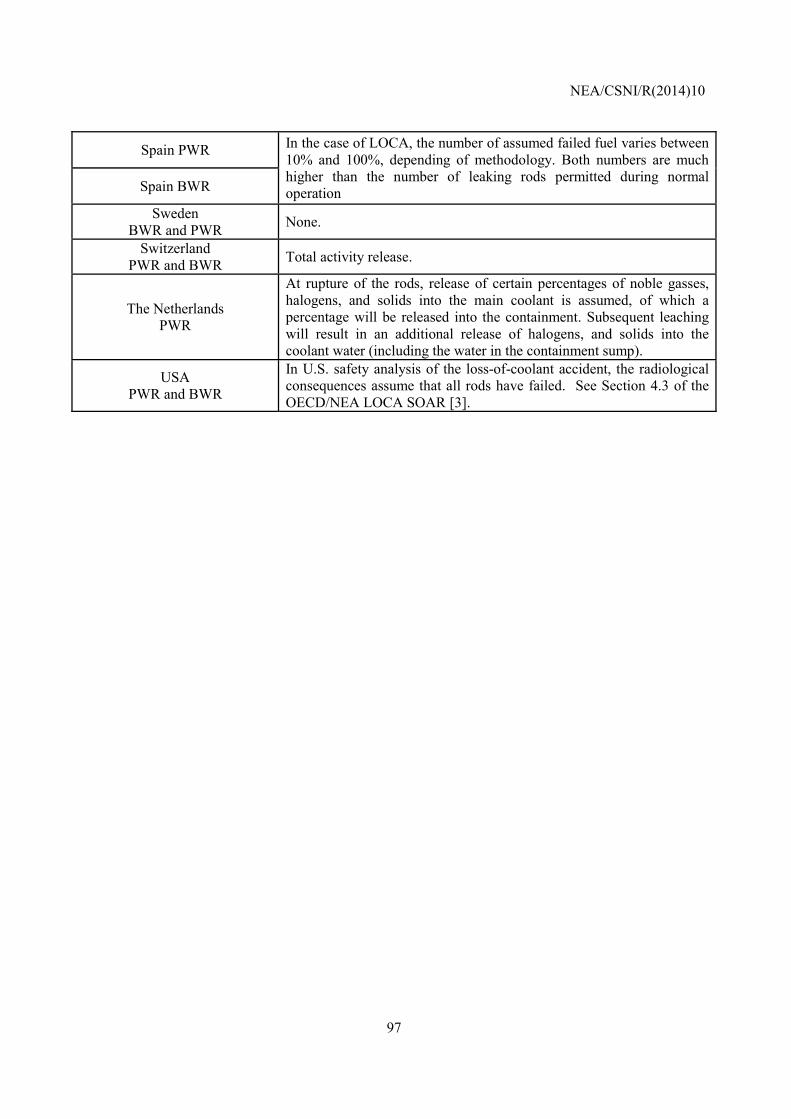
NEA/CSNI/R(2014)10
97
Spain PWR In the case of LOCA, the number of assumed failed fuel varies between 10% and 100%, depending of methodology. Both numbers are much higher than the number of leaking rods permitted during normal operation Spain BWR
Sweden BWR and PWR None.
Switzerland PWR and BWR Total activity release.
The Netherlands PWR
At rupture of the rods, release of certain percentages of noble gasses, halogens, and solids into the main coolant is assumed, of which a percentage will be released into the containment. Subsequent leaching will result in an additional release of halogens, and solids into the coolant water (including the water in the containment sump).
USA PWR and BWR
In U.S. safety analysis of the loss-of-coolant accident, the radiological consequences assume that all rods have failed. See Section 4.3 of the OECD/NEA LOCA SOAR [3].
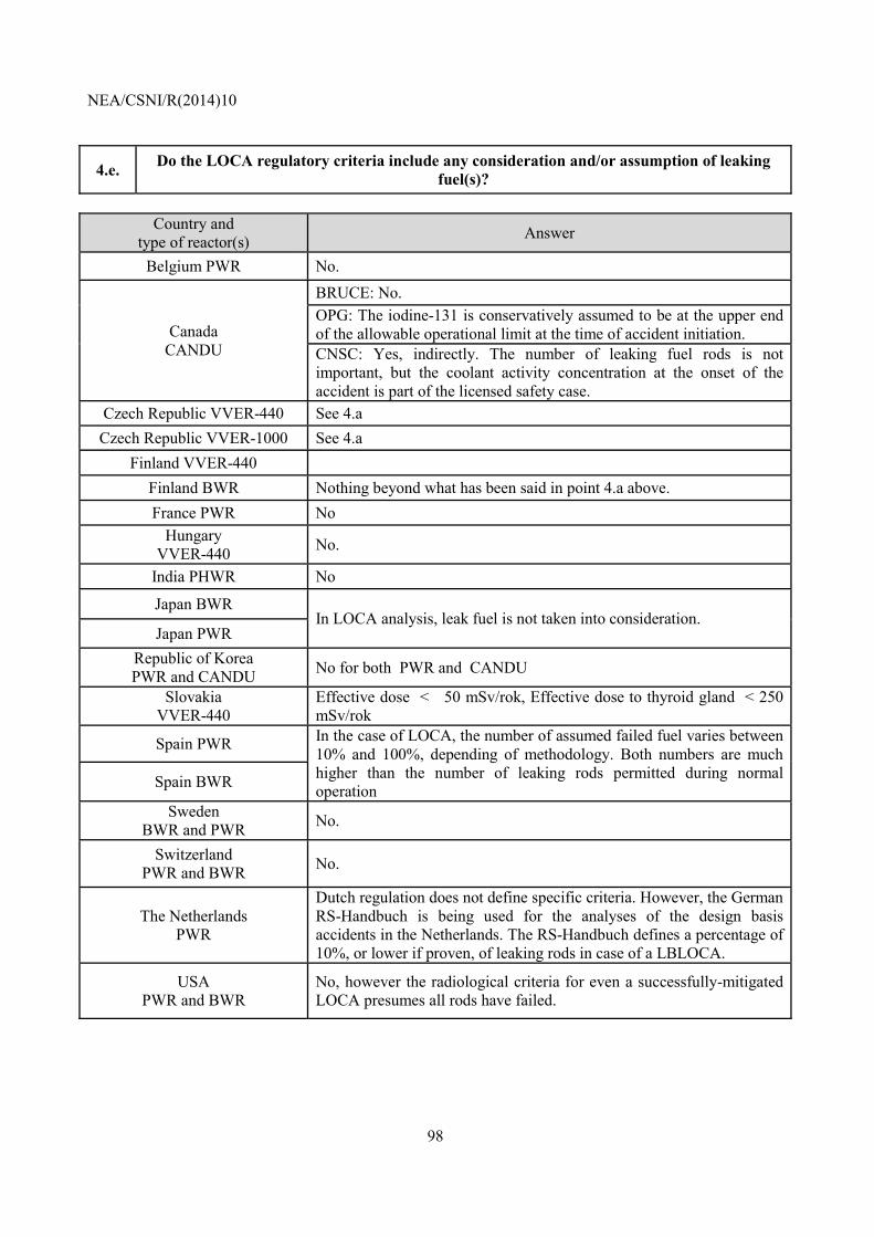
NEA/CSNI/R(2014)10
98
4.e. Do the LOCA regulatory criteria include any consideration and/or assumption of leaking fuel(s)?
Country and
type of reactor(s) Answer
Belgium PWR No.
Canada CANDU
BRUCE: No. OPG: The iodine-131 is conservatively assumed to be at the upper end of the allowable operational limit at the time of accident initiation. CNSC: Yes, indirectly. The number of leaking fuel rods is not important, but the coolant activity concentration at the onset of the accident is part of the licensed safety case.
Czech Republic VVER-440 See 4.a Czech Republic VVER-1000 See 4.a
Finland VVER-440 Finland BWR Nothing beyond what has been said in point 4.a above. France PWR No
Hungary VVER-440 No.
India PHWR No
Japan BWR In LOCA analysis, leak fuel is not taken into consideration.
Japan PWR Republic of Korea PWR and CANDU No for both PWR and CANDU
Slovakia VVER-440
Effective dose < 50 mSv/rok, Effective dose to thyroid gland < 250 mSv/rok
Spain PWR In the case of LOCA, the number of assumed failed fuel varies between 10% and 100%, depending of methodology. Both numbers are much higher than the number of leaking rods permitted during normal operation Spain BWR
Sweden BWR and PWR No.
Switzerland PWR and BWR No.
The Netherlands PWR
Dutch regulation does not define specific criteria. However, the German RS-Handbuch is being used for the analyses of the design basis accidents in the Netherlands. The RS-Handbuch defines a percentage of 10%, or lower if proven, of leaking rods in case of a LBLOCA.
USA PWR and BWR
No, however the radiological criteria for even a successfully-mitigated LOCA presumes all rods have failed.
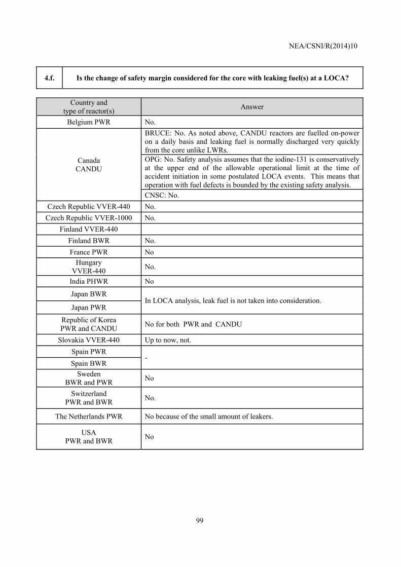
NEA/CSNI/R(2014)10
99
4.f. Is the change of safety margin considered for the core with leaking fuel(s) at a LOCA?
Country and
type of reactor(s) Answer
Belgium PWR No.
Canada CANDU
BRUCE: No. As noted above, CANDU reactors are fuelled on-power on a daily basis and leaking fuel is normally discharged very quickly from the core unlike LWRs. OPG: No. Safety analysis assumes that the iodine-131 is conservatively at the upper end of the allowable operational limit at the time of accident initiation in some postulated LOCA events. This means that operation with fuel defects is bounded by the existing safety analysis. CNSC: No.
Czech Republic VVER-440 No. Czech Republic VVER-1000 No.
Finland VVER-440 Finland BWR No. France PWR No
Hungary VVER-440 No.
India PHWR No
Japan BWR In LOCA analysis, leak fuel is not taken into consideration.
Japan PWR
Republic of Korea PWR and CANDU No for both PWR and CANDU
Slovakia VVER-440 Up to now, not. Spain PWR
- Spain BWR
Sweden BWR and PWR No
Switzerland PWR and BWR No.
The Netherlands PWR No because of the small amount of leakers.
USA PWR and BWR No
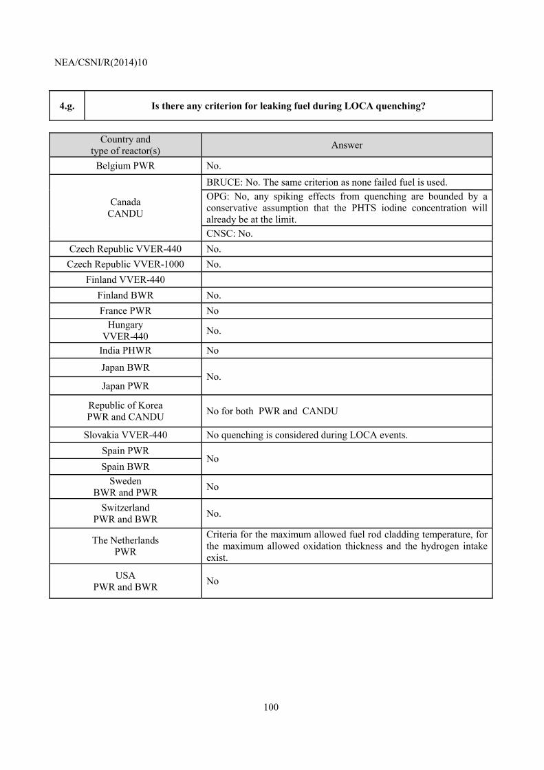
NEA/CSNI/R(2014)10
100
4.g. Is there any criterion for leaking fuel during LOCA quenching?
Country and
type of reactor(s) Answer
Belgium PWR No.
Canada CANDU
BRUCE: No. The same criterion as none failed fuel is used. OPG: No, any spiking effects from quenching are bounded by a conservative assumption that the PHTS iodine concentration will already be at the limit. CNSC: No.
Czech Republic VVER-440 No. Czech Republic VVER-1000 No.
Finland VVER-440 Finland BWR No. France PWR No
Hungary VVER-440 No.
India PHWR No
Japan BWR No.
Japan PWR
Republic of Korea PWR and CANDU No for both PWR and CANDU
Slovakia VVER-440 No quenching is considered during LOCA events. Spain PWR
No Spain BWR
Sweden BWR and PWR No
Switzerland PWR and BWR No.
The Netherlands PWR
Criteria for the maximum allowed fuel rod cladding temperature, for the maximum allowed oxidation thickness and the hydrogen intake exist.
USA PWR and BWR No
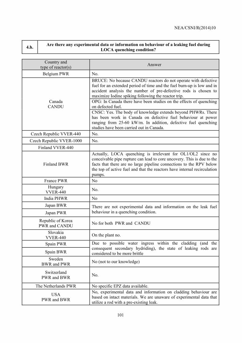
NEA/CSNI/R(2014)10
101
4.h. Are there any experimental data or information on behaviour of a leaking fuel during LOCA quenching condition?
Country and
type of reactor(s) Answer
Belgium PWR No.
Canada CANDU
BRUCE: No because CANDU reactors do not operate with defective fuel for an extended period of time and the fuel burn-up is low and in accident analysis the number of pre-defective rods is chosen to maximize Iodine spiking following the reactor trip. OPG: In Canada there have been studies on the effects of quenching on defected fuel. CNSC: Yes. The body of knowledge extends beyond PHWRs. There has been work in Canada on defective fuel behaviour at power ranging from 25-60 kW/m. In addition, defective fuel quenching studies have been carried out in Canada.
Czech Republic VVER-440 No. Czech Republic VVER-1000 No.
Finland VVER-440
Finland BWR
Actually, LOCA quenching is irrelevant for OL1/OL2 since no conceivable pipe rupture can lead to core uncovery. This is due to the facts that there are no large pipeline connections to the RPV below the top of active fuel and that the reactors have internal recirculation pumps.
France PWR No Hungary
VVER-440 No.
India PHWR No Japan BWR There are not experimental data and information on the leak fuel
behaviour in a quenching condition. Japan PWR
Republic of Korea PWR and CANDU No for both PWR and CANDU
Slovakia VVER-440 On the plant no.
Spain PWR Due to possible water ingress within the cladding (and the consequent secondary hydriding), the state of leaking rods are considered to be more brittle Spain BWR
Sweden BWR and PWR No (not to our knowledge)
Switzerland PWR and BWR No.
The Netherlands PWR No specific EPZ data available.
USA PWR and BWR
No, experimental data and information on cladding behaviour are based on intact materials. We are unaware of experimental data that utilize a rod with a pre-existing leak.
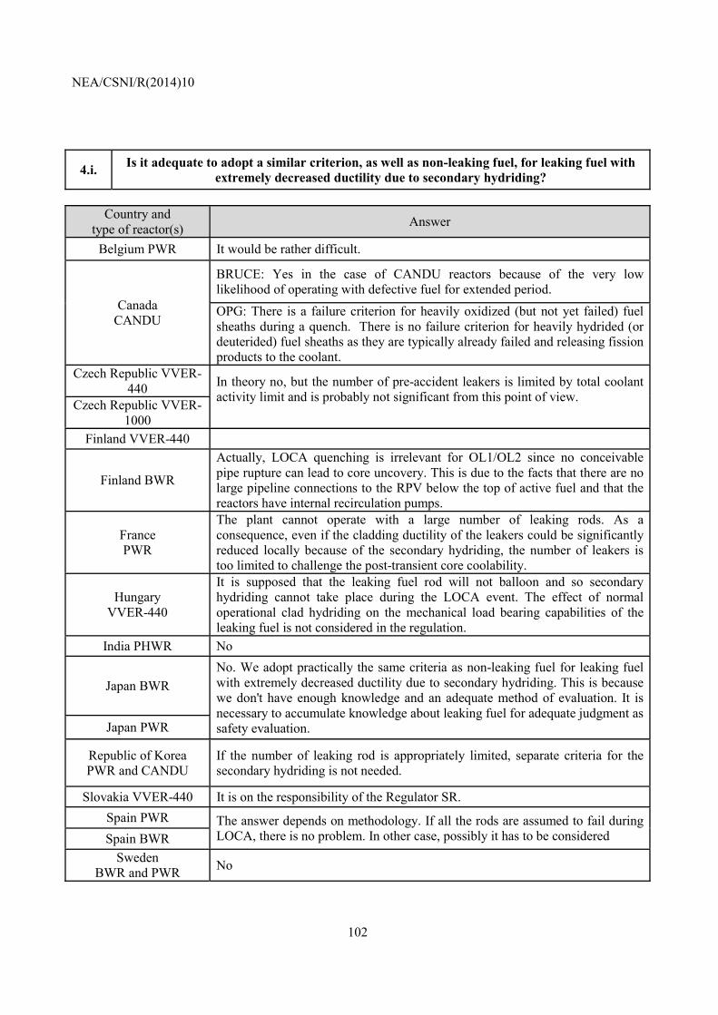
NEA/CSNI/R(2014)10
102
4.i. Is it adequate to adopt a similar criterion, as well as non-leaking fuel, for leaking fuel with extremely decreased ductility due to secondary hydriding?
Country and
type of reactor(s) Answer
Belgium PWR It would be rather difficult.
Canada CANDU
BRUCE: Yes in the case of CANDU reactors because of the very low likelihood of operating with defective fuel for extended period.
OPG: There is a failure criterion for heavily oxidized (but not yet failed) fuel sheaths during a quench. There is no failure criterion for heavily hydrided (or deuterided) fuel sheaths as they are typically already failed and releasing fission products to the coolant.
Czech Republic VVER-440 In theory no, but the number of pre-accident leakers is limited by total coolant
activity limit and is probably not significant from this point of view. Czech Republic VVER-
1000 Finland VVER-440
Finland BWR
Actually, LOCA quenching is irrelevant for OL1/OL2 since no conceivable pipe rupture can lead to core uncovery. This is due to the facts that there are no large pipeline connections to the RPV below the top of active fuel and that the reactors have internal recirculation pumps.
France PWR
The plant cannot operate with a large number of leaking rods. As a consequence, even if the cladding ductility of the leakers could be significantly reduced locally because of the secondary hydriding, the number of leakers is too limited to challenge the post-transient core coolability.
Hungary VVER-440
It is supposed that the leaking fuel rod will not balloon and so secondary hydriding cannot take place during the LOCA event. The effect of normal operational clad hydriding on the mechanical load bearing capabilities of the leaking fuel is not considered in the regulation.
India PHWR No
Japan BWR No. We adopt practically the same criteria as non-leaking fuel for leaking fuel with extremely decreased ductility due to secondary hydriding. This is because we don't have enough knowledge and an adequate method of evaluation. It is necessary to accumulate knowledge about leaking fuel for adequate judgment as safety evaluation. Japan PWR
Republic of Korea PWR and CANDU
If the number of leaking rod is appropriately limited, separate criteria for the secondary hydriding is not needed.
Slovakia VVER-440 It is on the responsibility of the Regulator SR. Spain PWR The answer depends on methodology. If all the rods are assumed to fail during
LOCA, there is no problem. In other case, possibly it has to be considered Spain BWR Sweden
BWR and PWR No
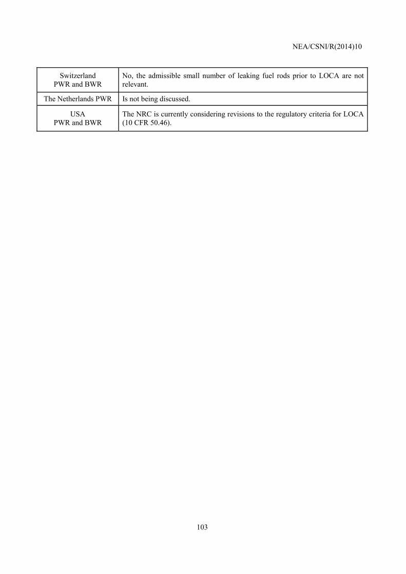
NEA/CSNI/R(2014)10
103
Switzerland PWR and BWR
No, the admissible small number of leaking fuel rods prior to LOCA are not relevant.
The Netherlands PWR Is not being discussed.
USA PWR and BWR
The NRC is currently considering revisions to the regulatory criteria for LOCA (10 CFR 50.46).
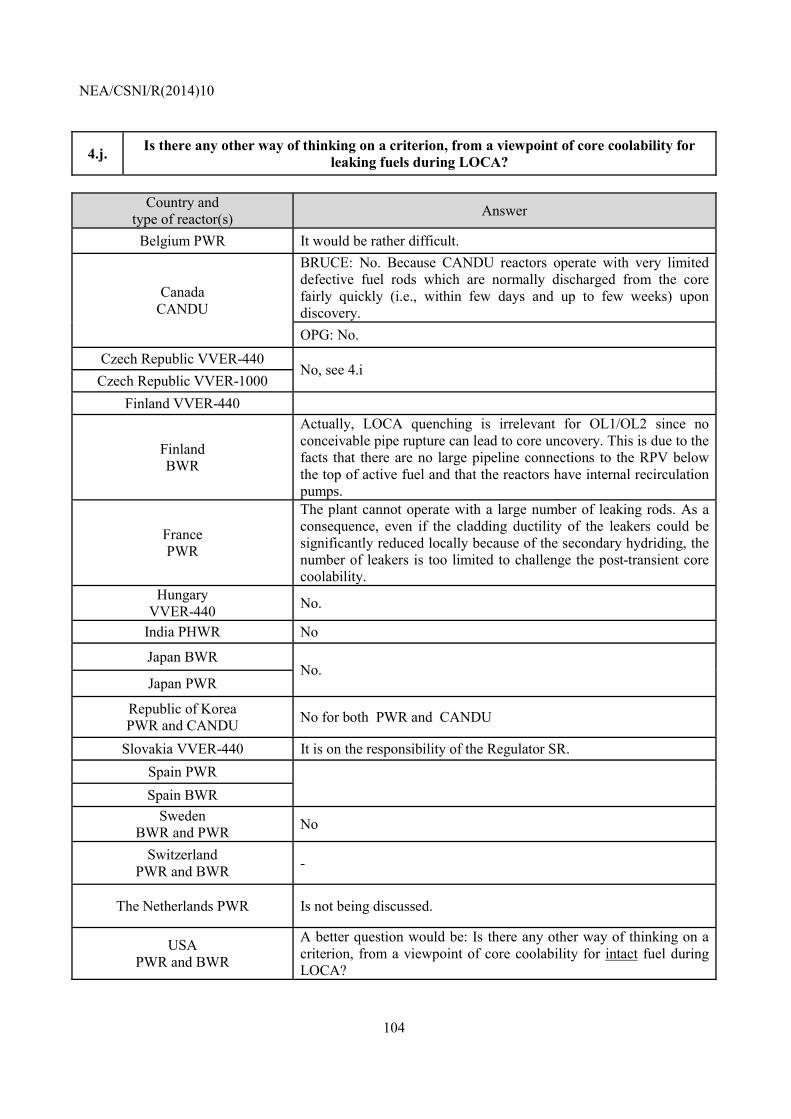
NEA/CSNI/R(2014)10
104
4.j. Is there any other way of thinking on a criterion, from a viewpoint of core coolability for leaking fuels during LOCA?
Country and
type of reactor(s) Answer
Belgium PWR It would be rather difficult.
Canada CANDU
BRUCE: No. Because CANDU reactors operate with very limited defective fuel rods which are normally discharged from the core fairly quickly (i.e., within few days and up to few weeks) upon discovery. OPG: No.
Czech Republic VVER-440 No, see 4.i
Czech Republic VVER-1000 Finland VVER-440
Finland BWR
Actually, LOCA quenching is irrelevant for OL1/OL2 since no conceivable pipe rupture can lead to core uncovery. This is due to the facts that there are no large pipeline connections to the RPV below the top of active fuel and that the reactors have internal recirculation pumps.
France PWR
The plant cannot operate with a large number of leaking rods. As a consequence, even if the cladding ductility of the leakers could be significantly reduced locally because of the secondary hydriding, the number of leakers is too limited to challenge the post-transient core coolability.
Hungary VVER-440 No.
India PHWR No
Japan BWR No.
Japan PWR
Republic of Korea PWR and CANDU No for both PWR and CANDU
Slovakia VVER-440 It is on the responsibility of the Regulator SR. Spain PWR
Spain BWR
Sweden BWR and PWR No
Switzerland PWR and BWR -
The Netherlands PWR Is not being discussed.
USA PWR and BWR
A better question would be: Is there any other way of thinking on a criterion, from a viewpoint of core coolability for intact fuel during LOCA?
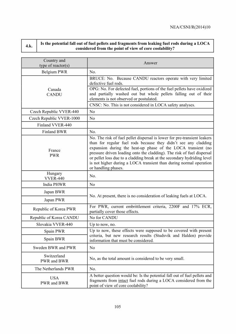
NEA/CSNI/R(2014)10
105
4.k. Is the potential fall out of fuel pellets and fragments from leaking fuel rods during a LOCA considered from the point of view of core coolability?
Country and
type of reactor(s) Answer
Belgium PWR No.
Canada CANDU
BRUCE: No. Because CANDU reactors operate with very limited defective fuel rods. OPG: No. For defected fuel, portions of the fuel pellets have oxidized and partially washed out but whole pellets falling out of their elements is not observed or postulated. CNSC: No. This is not considered in LOCA safety analyses.
Czech Republic VVER-440 No Czech Republic VVER-1000 No
Finland VVER-440 Finland BWR No.
France PWR
No. The risk of fuel pellet dispersal is lower for pre-transient leakers than for regular fuel rods because they didn’t see any cladding expansion during the heat-up phase of the LOCA transient (no pressure driven loading onto the cladding). The risk of fuel dispersal or pellet loss due to a cladding break at the secondary hydriding level is not higher during a LOCA transient than during normal operation or handling phases.
Hungary VVER-440 No.
India PHWR No
Japan BWR No. At present, there is no consideration of leaking fuels at LOCA.
Japan PWR
Republic of Korea PWR For PWR, current embrittlement criteria, 2200F and 17% ECR, partially cover those effects.
Republic of Korea CANDU No for CANDU Slovakia VVER-440 Up to now, no.
Spain PWR Up to now, these effects were supposed to be covered with present criteria, but new research results (Studsvik and Halden) provide information that must be considered. Spain BWR
Sweden BWR and PWR No
Switzerland PWR and BWR No, as the total amount is considered to be very small.
The Netherlands PWR No.
USA PWR and BWR
A better question would be: Is the potential fall out of fuel pellets and fragments from intact fuel rods during a LOCA considered from the point of view of core coolability?
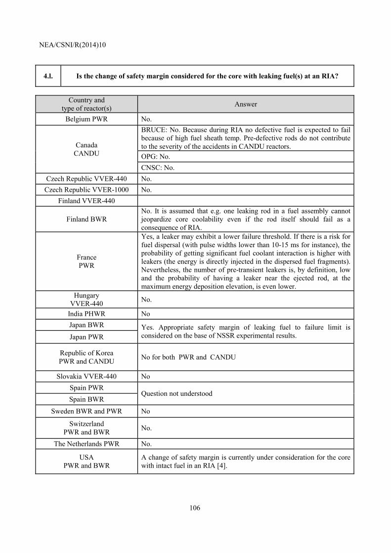
NEA/CSNI/R(2014)10
106
4.l. Is the change of safety margin considered for the core with leaking fuel(s) at an RIA?
Country and
type of reactor(s) Answer
Belgium PWR No.
Canada CANDU
BRUCE: No. Because during RIA no defective fuel is expected to fail because of high fuel sheath temp. Pre-defective rods do not contribute to the severity of the accidents in CANDU reactors. OPG: No. CNSC: No.
Czech Republic VVER-440 No. Czech Republic VVER-1000 No.
Finland VVER-440
Finland BWR No. It is assumed that e.g. one leaking rod in a fuel assembly cannot jeopardize core coolability even if the rod itself should fail as a consequence of RIA.
France PWR
Yes, a leaker may exhibit a lower failure threshold. If there is a risk for fuel dispersal (with pulse widths lower than 10-15 ms for instance), the probability of getting significant fuel coolant interaction is higher with leakers (the energy is directly injected in the dispersed fuel fragments). Nevertheless, the number of pre-transient leakers is, by definition, low and the probability of having a leaker near the ejected rod, at the maximum energy deposition elevation, is even lower.
Hungary VVER-440 No.
India PHWR No Japan BWR Yes. Appropriate safety margin of leaking fuel to failure limit is
considered on the base of NSSR experimental results. Japan PWR
Republic of Korea PWR and CANDU No for both PWR and CANDU
Slovakia VVER-440 No Spain PWR
Question not understood Spain BWR
Sweden BWR and PWR No
Switzerland PWR and BWR No.
The Netherlands PWR No.
USA PWR and BWR
A change of safety margin is currently under consideration for the core with intact fuel in an RIA [4].
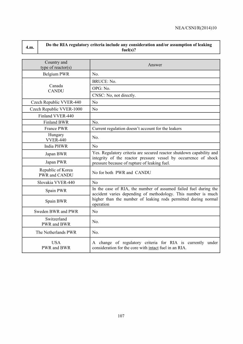
NEA/CSNI/R(2014)10
107
4.m. Do the RIA regulatory criteria include any consideration and/or assumption of leaking fuel(s)?
Country and
type of reactor(s) Answer
Belgium PWR No.
Canada CANDU
BRUCE: No. OPG: No. CNSC: No, not directly.
Czech Republic VVER-440 No Czech Republic VVER-1000 No
Finland VVER-440 Finland BWR No. France PWR Current regulation doesn’t account for the leakers
Hungary VVER-440 No.
India PHWR No
Japan BWR Yes. Regulatory criteria are secured reactor shutdown capability and integrity of the reactor pressure vessel by occurrence of shock pressure because of rupture of leaking fuel. Japan PWR
Republic of Korea PWR and CANDU No for both PWR and CANDU
Slovakia VVER-440 No
Spain PWR In the case of RIA, the number of assumed failed fuel during the accident varies depending of methodology. This number is much higher than the number of leaking rods permitted during normal operation
Spain BWR
Sweden BWR and PWR No
Switzerland PWR and BWR No.
The Netherlands PWR No.
USA PWR and BWR
A change of regulatory criteria for RIA is currently under consideration for the core with intact fuel in an RIA.
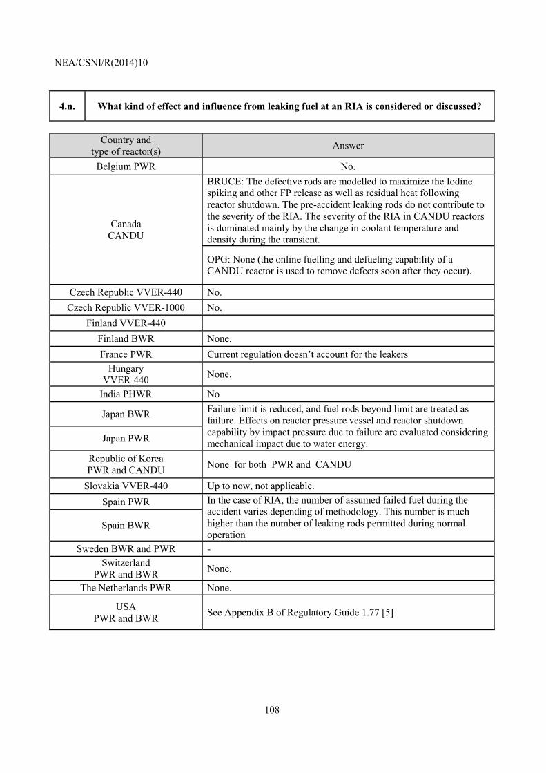
NEA/CSNI/R(2014)10
108
4.n. What kind of effect and influence from leaking fuel at an RIA is considered or discussed?
Country and
type of reactor(s) Answer
Belgium PWR No.
Canada CANDU
BRUCE: The defective rods are modelled to maximize the Iodine spiking and other FP release as well as residual heat following reactor shutdown. The pre-accident leaking rods do not contribute to the severity of the RIA. The severity of the RIA in CANDU reactors is dominated mainly by the change in coolant temperature and density during the transient.
OPG: None (the online fuelling and defueling capability of a CANDU reactor is used to remove defects soon after they occur).
Czech Republic VVER-440 No. Czech Republic VVER-1000 No.
Finland VVER-440 Finland BWR None. France PWR Current regulation doesn’t account for the leakers
Hungary VVER-440 None.
India PHWR No
Japan BWR Failure limit is reduced, and fuel rods beyond limit are treated as failure. Effects on reactor pressure vessel and reactor shutdown capability by impact pressure due to failure are evaluated considering mechanical impact due to water energy. Japan PWR
Republic of Korea PWR and CANDU None for both PWR and CANDU
Slovakia VVER-440 Up to now, not applicable. Spain PWR In the case of RIA, the number of assumed failed fuel during the
accident varies depending of methodology. This number is much higher than the number of leaking rods permitted during normal operation
Spain BWR
Sweden BWR and PWR - Switzerland
PWR and BWR None.
The Netherlands PWR None.
USA PWR and BWR See Appendix B of Regulatory Guide 1.77 [5]
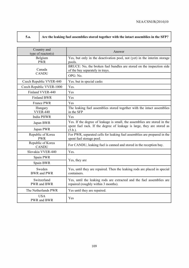
NEA/CSNI/R(2014)10
109
5.a. Are the leaking fuel assemblies stored together with the intact assemblies in the SFP?
Country and
type of reactor(s) Answer
Belgium PWR
Yes, but only in the deactivation pool, not (yet) in the interim storage pools.
Canada CANDU
BRUCE: No, the broken fuel bundles are stored on the inspection side of the bay separately in trays. OPG: No.
Czech Republic VVER-440 Yes. but in special casks Czech Republic VVER-1000 Yes.
Finland VVER-440 Yes Finland BWR Yes France PWR Yes
Hungary VVER-440
The leaking fuel assemblies stored together with the intact assemblies in the SFP
India PHWR Yes
Japan BWR Yes. If the degree of leakage is small, the assemblies are stored in the spent fuel rack. If the degree of leakage is large, they are stored as (5.b.). Japan PWR
Republic of Korea PWR
For PWR, separated cells for leaking fuel assemblies are prepared in the spent fuel storage pool.
Republic of Korea CANDU For CANDU, leaking fuel is canned and stored in the reception bay.
Slovakia VVER-440 Yes. Spain PWR
Yes, they are Spain BWR
Sweden BWR and PWR
Yes, until they are repaired. Then the leaking rods are placed in special containers.
Switzerland PWR and BWR
Yes, until the leaking rods are extracted and the fuel assemblies are repaired (roughly within 3 months).
The Netherlands PWR Yes until they are repaired. USA
PWR and BWR Yes
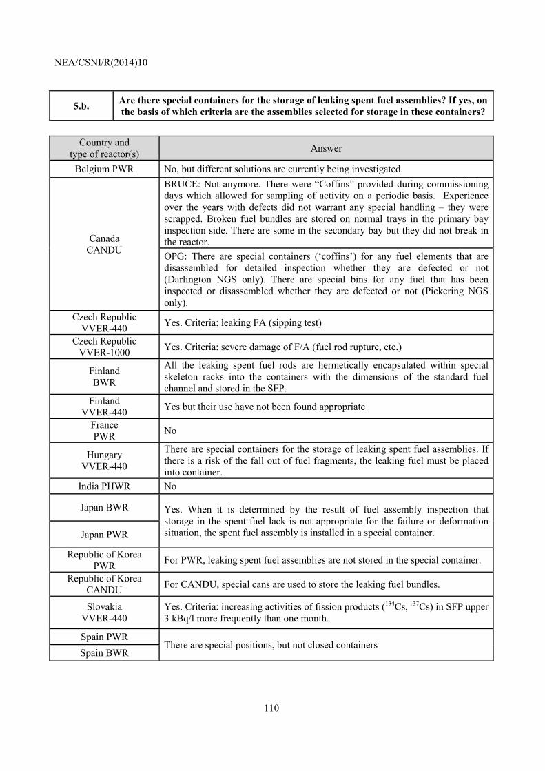
NEA/CSNI/R(2014)10
110
5.b. Are there special containers for the storage of leaking spent fuel assemblies? If yes, on the basis of which criteria are the assemblies selected for storage in these containers?
Country and
type of reactor(s) Answer
Belgium PWR No, but different solutions are currently being investigated.
Canada CANDU
BRUCE: Not anymore. There were “Coffins” provided during commissioning days which allowed for sampling of activity on a periodic basis. Experience over the years with defects did not warrant any special handling – they were scrapped. Broken fuel bundles are stored on normal trays in the primary bay inspection side. There are some in the secondary bay but they did not break in the reactor. OPG: There are special containers (‘coffins’) for any fuel elements that are disassembled for detailed inspection whether they are defected or not (Darlington NGS only). There are special bins for any fuel that has been inspected or disassembled whether they are defected or not (Pickering NGS only).
Czech Republic VVER-440 Yes. Criteria: leaking FA (sipping test)
Czech Republic VVER-1000 Yes. Criteria: severe damage of F/A (fuel rod rupture, etc.)
Finland BWR
All the leaking spent fuel rods are hermetically encapsulated within special skeleton racks into the containers with the dimensions of the standard fuel channel and stored in the SFP.
Finland VVER-440 Yes but their use have not been found appropriate
France PWR No
Hungary VVER-440
There are special containers for the storage of leaking spent fuel assemblies. If there is a risk of the fall out of fuel fragments, the leaking fuel must be placed into container.
India PHWR No
Japan BWR Yes. When it is determined by the result of fuel assembly inspection that storage in the spent fuel lack is not appropriate for the failure or deformation situation, the spent fuel assembly is installed in a special container. Japan PWR
Republic of Korea PWR For PWR, leaking spent fuel assemblies are not stored in the special container.
Republic of Korea CANDU For CANDU, special cans are used to store the leaking fuel bundles.
Slovakia VVER-440
Yes. Criteria: increasing activities of fission products (134Cs, 137Cs) in SFP upper 3 kBq/l more frequently than one month.
Spain PWR There are special positions, but not closed containers
Spain BWR
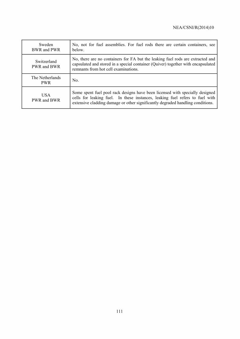
NEA/CSNI/R(2014)10
111
Sweden BWR and PWR
No, not for fuel assemblies. For fuel rods there are certain containers, see below.
Switzerland PWR and BWR
No, there are no containers for FA but the leaking fuel rods are extracted and capsulated and stored in a special container (Quiver) together with encapsulated remnants from hot cell examinations.
The Netherlands PWR No.
USA PWR and BWR
Some spent fuel pool rack designs have been licensed with specially designed cells for leaking fuel. In these instances, leaking fuel refers to fuel with extensive cladding damage or other significantly degraded handling conditions.
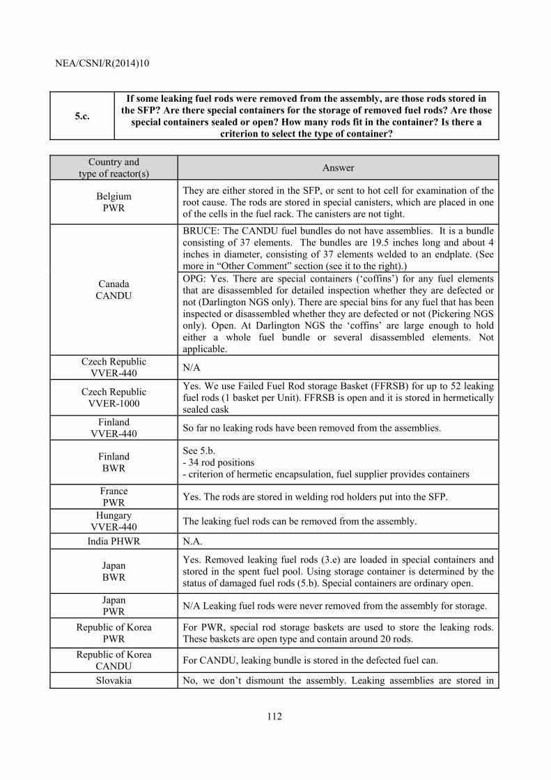
NEA/CSNI/R(2014)10
112
5.c.
If some leaking fuel rods were removed from the assembly, are those rods stored in the SFP? Are there special containers for the storage of removed fuel rods? Are those
special containers sealed or open? How many rods fit in the container? Is there a criterion to select the type of container?
Country and
type of reactor(s) Answer
Belgium PWR
They are either stored in the SFP, or sent to hot cell for examination of the root cause. The rods are stored in special canisters, which are placed in one of the cells in the fuel rack. The canisters are not tight.
Canada CANDU
BRUCE: The CANDU fuel bundles do not have assemblies. It is a bundle consisting of 37 elements. The bundles are 19.5 inches long and about 4 inches in diameter, consisting of 37 elements welded to an endplate. (See more in “Other Comment” section (see it to the right).) OPG: Yes. There are special containers (‘coffins’) for any fuel elements that are disassembled for detailed inspection whether they are defected or not (Darlington NGS only). There are special bins for any fuel that has been inspected or disassembled whether they are defected or not (Pickering NGS only). Open. At Darlington NGS the ‘coffins’ are large enough to hold either a whole fuel bundle or several disassembled elements. Not applicable.
Czech Republic VVER-440 N/A
Czech Republic VVER-1000
Yes. We use Failed Fuel Rod storage Basket (FFRSB) for up to 52 leaking fuel rods (1 basket per Unit). FFRSB is open and it is stored in hermetically sealed cask
Finland VVER-440 So far no leaking rods have been removed from the assemblies.
Finland BWR
See 5.b. - 34 rod positions - criterion of hermetic encapsulation, fuel supplier provides containers
France PWR Yes. The rods are stored in welding rod holders put into the SFP.
Hungary VVER-440 The leaking fuel rods can be removed from the assembly.
India PHWR N.A.
Japan BWR
Yes. Removed leaking fuel rods (3.e) are loaded in special containers and stored in the spent fuel pool. Using storage container is determined by the status of damaged fuel rods (5.b). Special containers are ordinary open.
Japan PWR N/A Leaking fuel rods were never removed from the assembly for storage.
Republic of Korea PWR
For PWR, special rod storage baskets are used to store the leaking rods. These baskets are open type and contain around 20 rods.
Republic of Korea CANDU For CANDU, leaking bundle is stored in the defected fuel can.
Slovakia No, we don’t dismount the assembly. Leaking assemblies are stored in
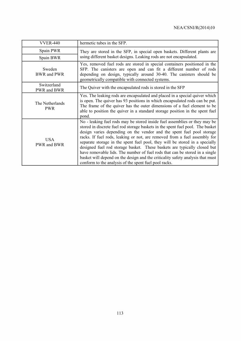
NEA/CSNI/R(2014)10
113
VVER-440 hermetic tubes in the SFP.
Spain PWR They are stored in the SFP, in special open baskets. Different plants are using different basket designs. Leaking rods are not encapsulated. Spain BWR
Sweden BWR and PWR
Yes, removed fuel rods are stored in special containers positioned in the SFP. The canisters are open and can fit a different number of rods depending on design, typically around 30-40. The canisters should be geometrically compatible with connected systems.
Switzerland PWR and BWR The Quiver with the encapsulated rods is stored in the SFP
The Netherlands PWR
Yes. The leaking rods are encapsulated and placed in a special quiver which is open. The quiver has 93 positions in which encapsulated rods can be put. The frame of the quiver has the outer dimensions of a fuel element to be able to position the quiver in a standard storage position in the spent fuel pond.
USA PWR and BWR
No - leaking fuel rods may be stored inside fuel assemblies or they may be stored in discrete fuel rod storage baskets in the spent fuel pool. The basket design varies depending on the vendor and the spent fuel pool storage racks. If fuel rods, leaking or not, are removed from a fuel assembly for separate storage in the spent fuel pool, they will be stored in a specially designed fuel rod storage basket. These baskets are typically closed but have removable lids. The number of fuel rods that can be stored in a single basket will depend on the design and the criticality safety analysis that must conform to the analysis of the spent fuel pool racks.
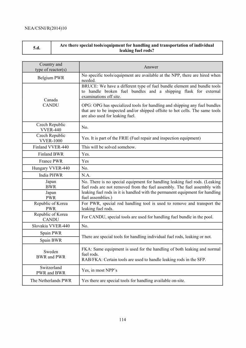
NEA/CSNI/R(2014)10
114
5.d. Are there special tools/equipment for handling and transportation of individual leaking fuel rods?
Country and
type of reactor(s) Answer
Belgium PWR No specific tools/equipment are available at the NPP, there are hired when needed.
Canada CANDU
BRUCE: We have a different type of fuel bundle element and bundle tools to handle broken fuel bundles and a shipping flask for external examinations off site.
OPG: OPG has specialized tools for handling and shipping any fuel bundles that are to be inspected and/or shipped offsite to hot cells. The same tools are also used for leaking fuel.
Czech Republic VVER-440 No.
Czech Republic VVER-1000 Yes. It is part of the FRIE (Fuel repair and inspection equipment)
Finland VVER-440 This will be solved somehow. Finland BWR Yes. France PWR Yes
Hungary VVER-440 No. India PHWR N.A.
Japan BWR
No. There is no special equipment for handling leaking fuel rods. (Leaking fuel rods are not removed from the fuel assembly. The fuel assembly with leaking fuel rods in it is handled with the permanent equipment for handling fuel assemblies.)
Japan PWR
Republic of Korea PWR
For PWR, special rod handling tool is used to remove and transport the leaking fuel rods.
Republic of Korea CANDU For CANDU, special tools are used for handling fuel bundle in the pool.
Slovakia VVER-440 No. Spain PWR
There are special tools for handling individual fuel rods, leaking or not. Spain BWR
Sweden BWR and PWR
FKA: Same equipment is used for the handling of both leaking and normal fuel rods. RAB/FKA: Certain tools are used to handle leaking rods in the SFP.
Switzerland PWR and BWR Yes, in most NPP’s
The Netherlands PWR Yes there are special tools for handling available on-site.
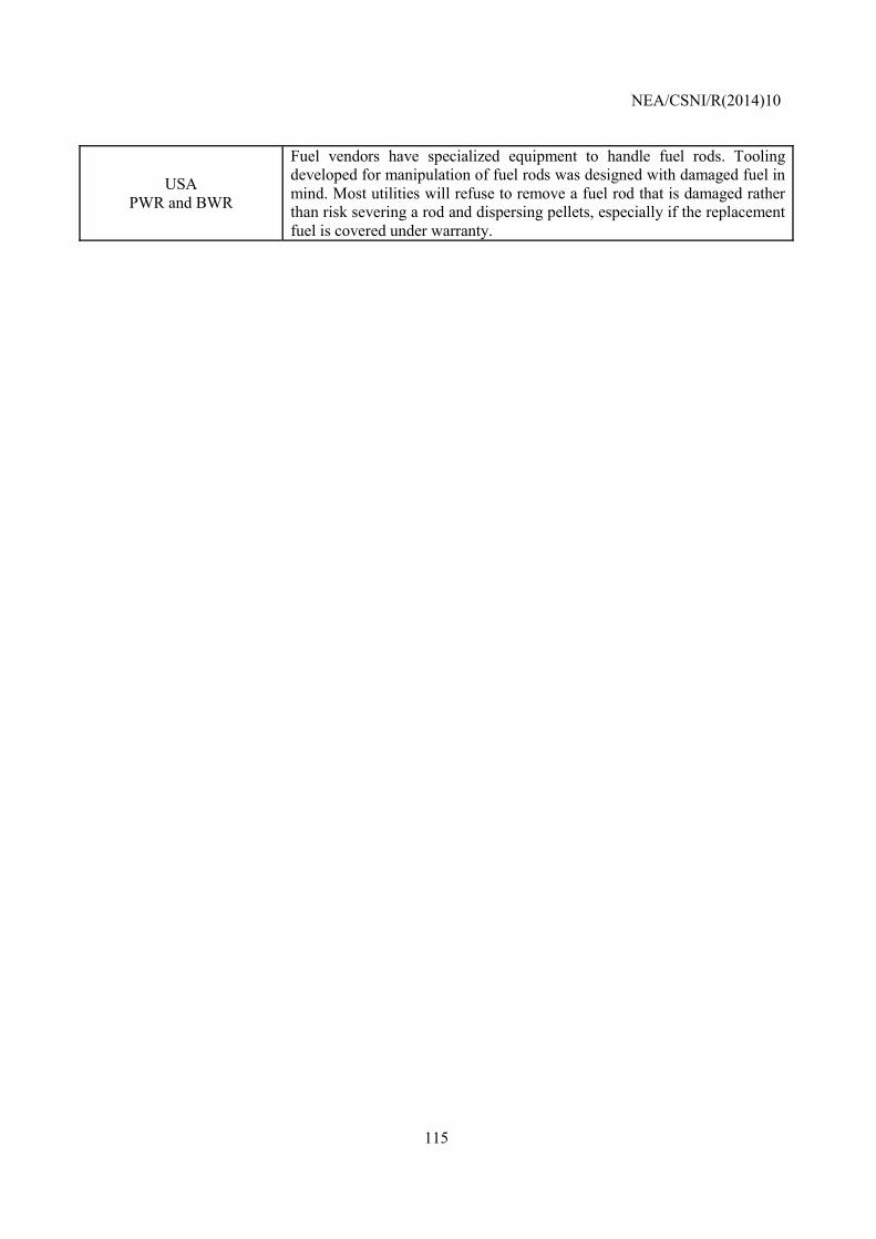
NEA/CSNI/R(2014)10
115
USA PWR and BWR
Fuel vendors have specialized equipment to handle fuel rods. Tooling developed for manipulation of fuel rods was designed with damaged fuel in mind. Most utilities will refuse to remove a fuel rod that is damaged rather than risk severing a rod and dispersing pellets, especially if the replacement fuel is covered under warranty.
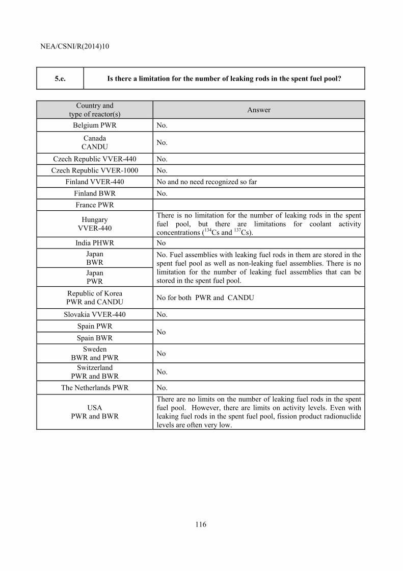
NEA/CSNI/R(2014)10
116
5.e. Is there a limitation for the number of leaking rods in the spent fuel pool?
Country and
type of reactor(s) Answer
Belgium PWR No.
Canada CANDU No.
Czech Republic VVER-440 No. Czech Republic VVER-1000 No.
Finland VVER-440 No and no need recognized so far Finland BWR No. France PWR
Hungary VVER-440
There is no limitation for the number of leaking rods in the spent fuel pool, but there are limitations for coolant activity concentrations (134Cs and 137Cs).
India PHWR No Japan BWR
No. Fuel assemblies with leaking fuel rods in them are stored in the spent fuel pool as well as non-leaking fuel assemblies. There is no limitation for the number of leaking fuel assemblies that can be stored in the spent fuel pool.
Japan PWR
Republic of Korea PWR and CANDU No for both PWR and CANDU
Slovakia VVER-440 No. Spain PWR
No Spain BWR
Sweden BWR and PWR No
Switzerland PWR and BWR No.
The Netherlands PWR No.
USA PWR and BWR
There are no limits on the number of leaking fuel rods in the spent fuel pool. However, there are limits on activity levels. Even with leaking fuel rods in the spent fuel pool, fission product radionuclide levels are often very low.
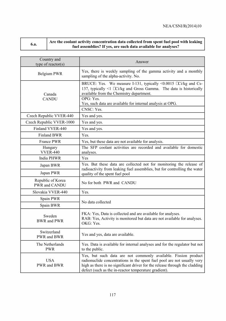
NEA/CSNI/R(2014)10
117
6.a. Are the coolant activity concentration data collected from spent fuel pool with leaking fuel assemblies? If yes, are such data available for analyses?
Country and
type of reactor(s) Answer
Belgium PWR Yes, there is weekly sampling of the gamma activity and a monthly sampling of the alpha-activity. No.
Canada CANDU
BRUCE: Yes. We measure I-131, typically <0.0015 µCi/kg and Cs-137, typically <1 µCi/kg and Gross Gamma. The data is historically available from the Chemistry department. OPG: Yes. Yes, such data are available for internal analysis at OPG. CNSC: Yes.
Czech Republic VVER-440 Yes and yes. Czech Republic VVER-1000 Yes and yes.
Finland VVER-440 Yes and yes. Finland BWR Yes. France PWR Yes, but these data are not available for analysis.
Hungary VVER-440
The SFP coolant activities are recorded and available for domestic analyses.
India PHWR Yes
Japan BWR Yes. But these data are collected not for monitoring the release of radioactivity from leaking fuel assemblies, but for controlling the water quality of the spent fuel pool Japan PWR
Republic of Korea PWR and CANDU No for both PWR and CANDU
Slovakia VVER-440 Yes. Spain PWR
No data collected Spain BWR
Sweden BWR and PWR
FKA: Yes, Data is collected and are available for analyses. RAB: Yes, Activity is monitored but data are not available for analyses. OKG: Yes.
Switzerland PWR and BWR Yes and yes, data are available.
The Netherlands PWR
Yes. Data is available for internal analyses and for the regulator but not to the public.
USA PWR and BWR
Yes, but such data are not commonly available. Fission product radionuclide concentrations in the spent fuel pool are not usually very high as there is no significant driver for the release through the cladding defect (such as the in-reactor temperature gradient).
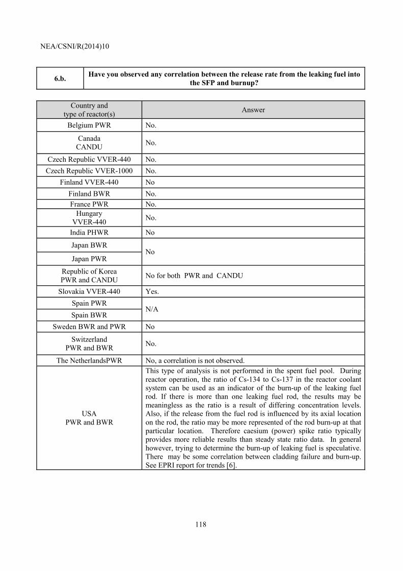
NEA/CSNI/R(2014)10
118
6.b. Have you observed any correlation between the release rate from the leaking fuel into the SFP and burnup?
Country and type of reactor(s) Answer
Belgium PWR No.
Canada CANDU No.
Czech Republic VVER-440 No. Czech Republic VVER-1000 No.
Finland VVER-440 No Finland BWR No. France PWR No.
Hungary VVER-440 No.
India PHWR No
Japan BWR No
Japan PWR
Republic of Korea PWR and CANDU No for both PWR and CANDU
Slovakia VVER-440 Yes. Spain PWR
N/A Spain BWR
Sweden BWR and PWR No
Switzerland PWR and BWR No.
The NetherlandsPWR No, a correlation is not observed.
USA PWR and BWR
This type of analysis is not performed in the spent fuel pool. During reactor operation, the ratio of Cs-134 to Cs-137 in the reactor coolant system can be used as an indicator of the burn-up of the leaking fuel rod. If there is more than one leaking fuel rod, the results may be meaningless as the ratio is a result of differing concentration levels. Also, if the release from the fuel rod is influenced by its axial location on the rod, the ratio may be more represented of the rod burn-up at that particular location. Therefore caesium (power) spike ratio typically provides more reliable results than steady state ratio data. In general however, trying to determine the burn-up of leaking fuel is speculative. There may be some correlation between cladding failure and burn-up. See EPRI report for trends [6].
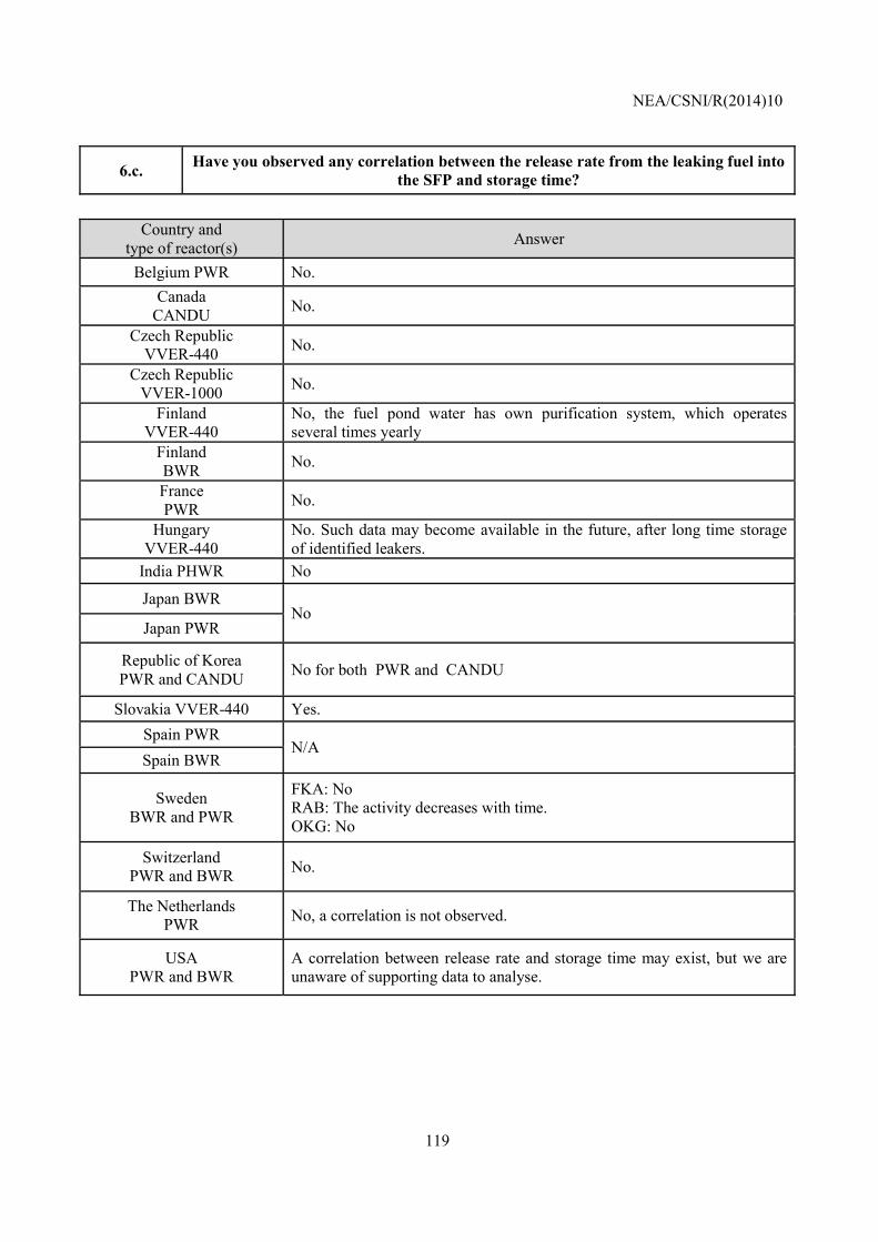
NEA/CSNI/R(2014)10
119
6.c. Have you observed any correlation between the release rate from the leaking fuel into the SFP and storage time?
Country and
type of reactor(s) Answer
Belgium PWR No. Canada
CANDU No.
Czech Republic VVER-440 No.
Czech Republic VVER-1000 No.
Finland VVER-440
No, the fuel pond water has own purification system, which operates several times yearly
Finland BWR No.
France PWR No.
Hungary VVER-440
No. Such data may become available in the future, after long time storage of identified leakers.
India PHWR No
Japan BWR No
Japan PWR
Republic of Korea PWR and CANDU No for both PWR and CANDU
Slovakia VVER-440 Yes. Spain PWR
N/A Spain BWR
Sweden BWR and PWR
FKA: No RAB: The activity decreases with time. OKG: No
Switzerland PWR and BWR No.
The Netherlands PWR No, a correlation is not observed.
USA PWR and BWR
A correlation between release rate and storage time may exist, but we are unaware of supporting data to analyse.
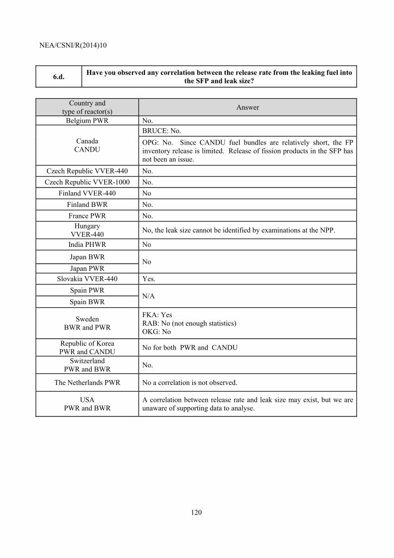
NEA/CSNI/R(2014)10
120
6.d. Have you observed any correlation between the release rate from the leaking fuel into the SFP and leak size?
Country and
type of reactor(s) Answer
Belgium PWR No.
Canada CANDU
BRUCE: No. OPG: No. Since CANDU fuel bundles are relatively short, the FP inventory release is limited. Release of fission products in the SFP has not been an issue.
Czech Republic VVER-440 No. Czech Republic VVER-1000 No.
Finland VVER-440 No Finland BWR No. France PWR No.
Hungary VVER-440 No, the leak size cannot be identified by examinations at the NPP.
India PHWR No
Japan BWR No Japan PWR
Slovakia VVER-440 Yes. Spain PWR
N/A Spain BWR
Sweden BWR and PWR
FKA: Yes RAB: No (not enough statistics) OKG: No
Republic of Korea PWR and CANDU No for both PWR and CANDU
Switzerland PWR and BWR No.
The Netherlands PWR No a correlation is not observed.
USA PWR and BWR
A correlation between release rate and leak size may exist, but we are unaware of supporting data to analyse.
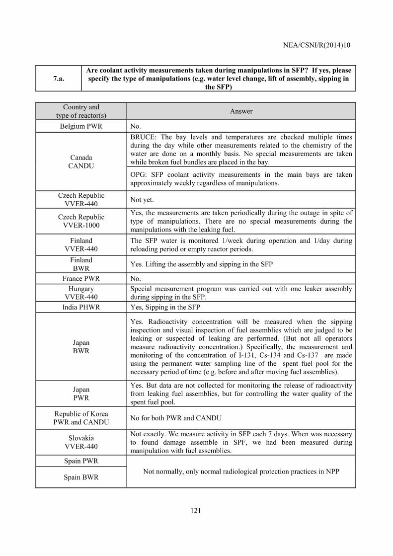
NEA/CSNI/R(2014)10
121
7.a. Are coolant activity measurements taken during manipulations in SFP? If yes, please specify the type of manipulations (e.g. water level change, lift of assembly, sipping in
the SFP)
Country and type of reactor(s) Answer
Belgium PWR No.
Canada CANDU
BRUCE: The bay levels and temperatures are checked multiple times during the day while other measurements related to the chemistry of the water are done on a monthly basis. No special measurements are taken while broken fuel bundles are placed in the bay.
OPG: SFP coolant activity measurements in the main bays are taken approximately weekly regardless of manipulations.
Czech Republic VVER-440 Not yet.
Czech Republic VVER-1000
Yes, the measurements are taken periodically during the outage in spite of type of manipulations. There are no special measurements during the manipulations with the leaking fuel.
Finland VVER-440
The SFP water is monitored 1/week during operation and 1/day during reloading period or empty reactor periods.
Finland BWR Yes. Lifting the assembly and sipping in the SFP
France PWR No. Hungary
VVER-440 Special measurement program was carried out with one leaker assembly during sipping in the SFP.
India PHWR Yes, Sipping in the SFP
Japan BWR
Yes. Radioactivity concentration will be measured when the sipping inspection and visual inspection of fuel assemblies which are judged to be leaking or suspected of leaking are performed. (But not all operators measure radioactivity concentration.) Specifically, the measurement and monitoring of the concentration of I-131, Cs-134 and Cs-137 are made using the permanent water sampling line of the spent fuel pool for the necessary period of time (e.g. before and after moving fuel assemblies).
Japan PWR
Yes. But data are not collected for monitoring the release of radioactivity from leaking fuel assemblies, but for controlling the water quality of the spent fuel pool.
Republic of Korea PWR and CANDU No for both PWR and CANDU
Slovakia VVER-440
Not exactly. We measure activity in SFP each 7 days. When was necessary to found damage assemble in SPF, we had been measured during manipulation with fuel assemblies.
Spain PWR Not normally, only normal radiological protection practices in NPP
Spain BWR
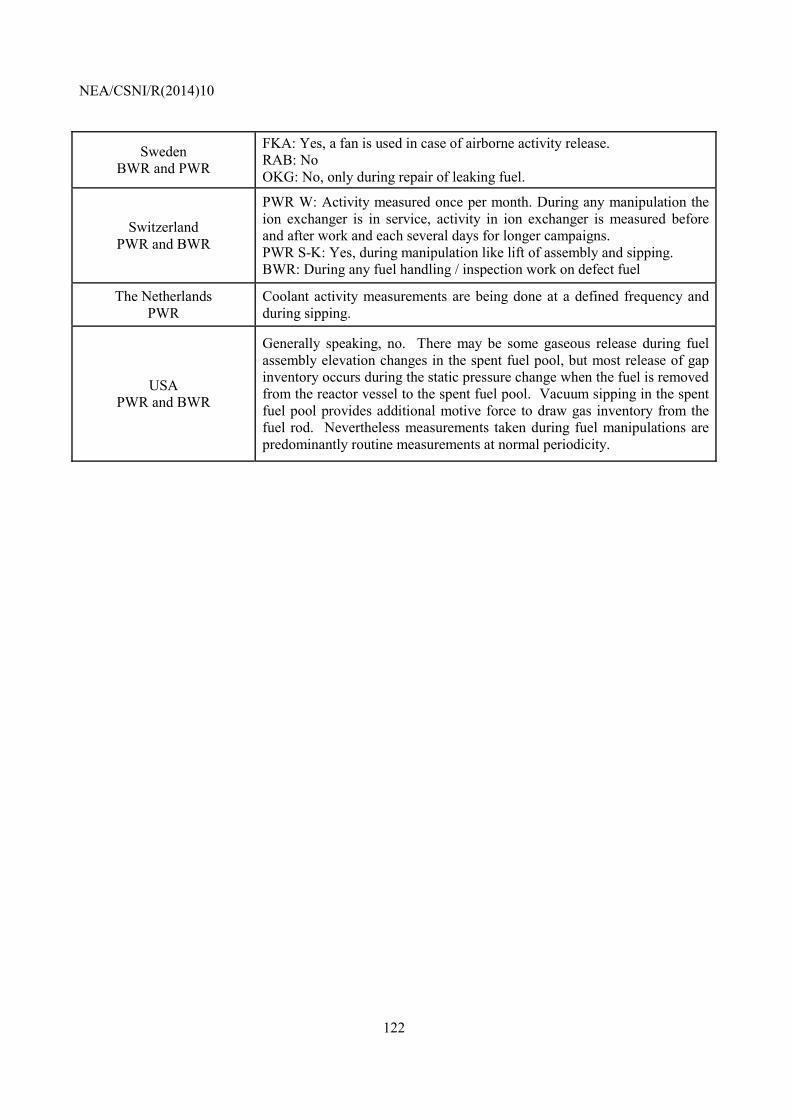
NEA/CSNI/R(2014)10
122
Sweden BWR and PWR
FKA: Yes, a fan is used in case of airborne activity release. RAB: No OKG: No, only during repair of leaking fuel.
Switzerland PWR and BWR
PWR W: Activity measured once per month. During any manipulation the ion exchanger is in service, activity in ion exchanger is measured before and after work and each several days for longer campaigns. PWR S-K: Yes, during manipulation like lift of assembly and sipping. BWR: During any fuel handling / inspection work on defect fuel
The Netherlands PWR
Coolant activity measurements are being done at a defined frequency and during sipping.
USA PWR and BWR
Generally speaking, no. There may be some gaseous release during fuel assembly elevation changes in the spent fuel pool, but most release of gap inventory occurs during the static pressure change when the fuel is removed from the reactor vessel to the spent fuel pool. Vacuum sipping in the spent fuel pool provides additional motive force to draw gas inventory from the fuel rod. Nevertheless measurements taken during fuel manipulations are predominantly routine measurements at normal periodicity.
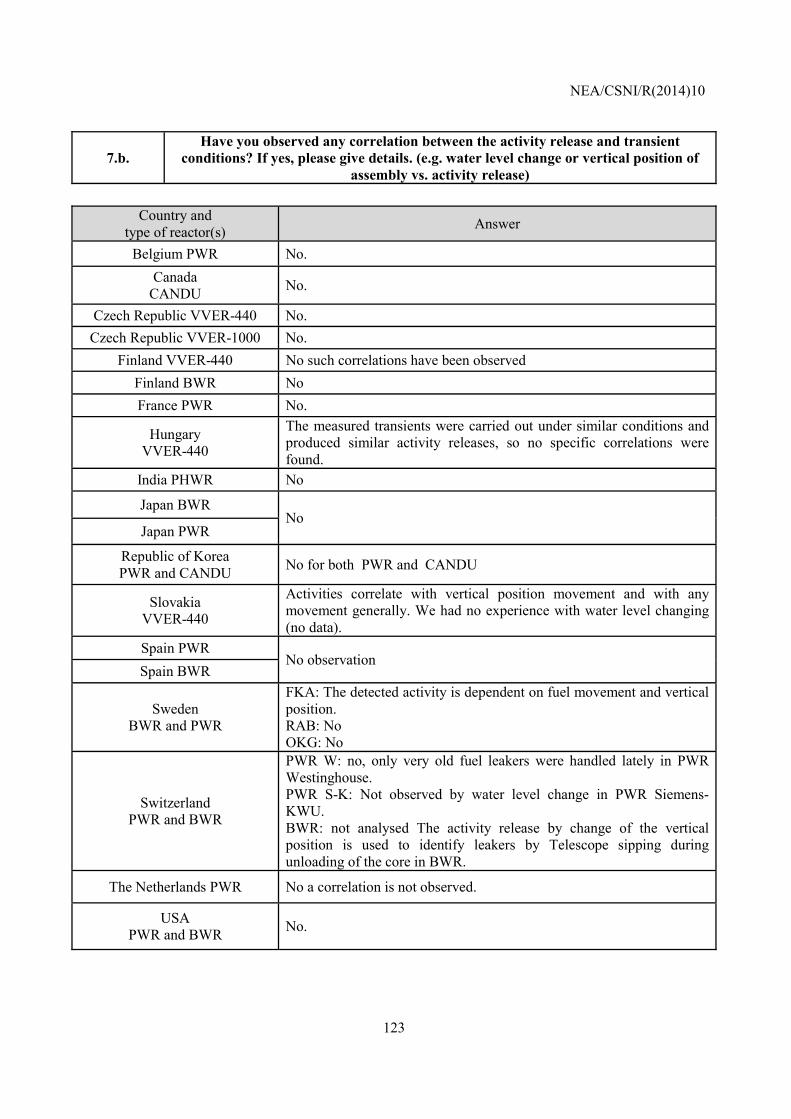
NEA/CSNI/R(2014)10
123
7.b. Have you observed any correlation between the activity release and transient
conditions? If yes, please give details. (e.g. water level change or vertical position of assembly vs. activity release)
Country and
type of reactor(s) Answer
Belgium PWR No. Canada
CANDU No.
Czech Republic VVER-440 No. Czech Republic VVER-1000 No.
Finland VVER-440 No such correlations have been observed Finland BWR No France PWR No.
Hungary VVER-440
The measured transients were carried out under similar conditions and produced similar activity releases, so no specific correlations were found.
India PHWR No
Japan BWR No
Japan PWR
Republic of Korea PWR and CANDU No for both PWR and CANDU
Slovakia VVER-440
Activities correlate with vertical position movement and with any movement generally. We had no experience with water level changing (no data).
Spain PWR No observation
Spain BWR
Sweden BWR and PWR
FKA: The detected activity is dependent on fuel movement and vertical position. RAB: No OKG: No
Switzerland PWR and BWR
PWR W: no, only very old fuel leakers were handled lately in PWR Westinghouse. PWR S-K: Not observed by water level change in PWR Siemens-KWU. BWR: not analysed The activity release by change of the vertical position is used to identify leakers by Telescope sipping during unloading of the core in BWR.
The Netherlands PWR No a correlation is not observed.
USA PWR and BWR No.
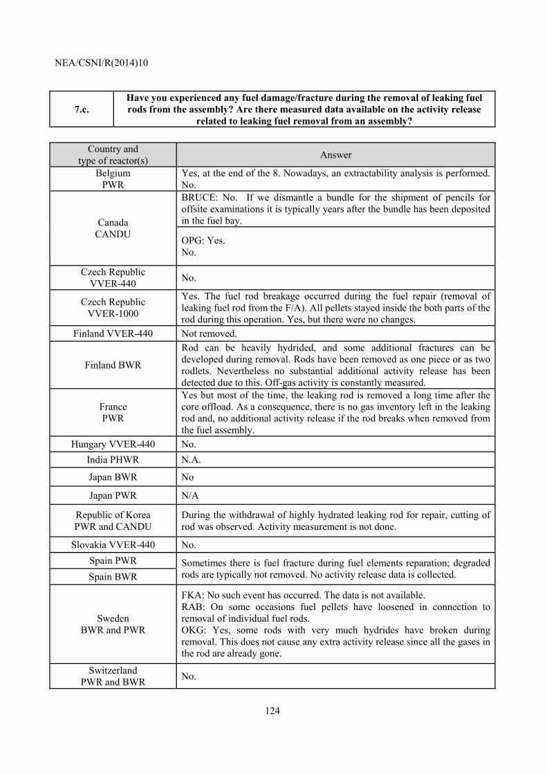
NEA/CSNI/R(2014)10
124
7.c. Have you experienced any fuel damage/fracture during the removal of leaking fuel rods from the assembly? Are there measured data available on the activity release
related to leaking fuel removal from an assembly?
Country and type of reactor(s) Answer
Belgium PWR
Yes, at the end of the 8. Nowadays, an extractability analysis is performed. No.
Canada CANDU
BRUCE: No. If we dismantle a bundle for the shipment of pencils for offsite examinations it is typically years after the bundle has been deposited in the fuel bay.
OPG: Yes. No.
Czech Republic VVER-440 No.
Czech Republic VVER-1000
Yes. The fuel rod breakage occurred during the fuel repair (removal of leaking fuel rod from the F/A). All pellets stayed inside the both parts of the rod during this operation. Yes, but there were no changes.
Finland VVER-440 Not removed.
Finland BWR
Rod can be heavily hydrided, and some additional fractures can be developed during removal. Rods have been removed as one piece or as two rodlets. Nevertheless no substantial additional activity release has been detected due to this. Off-gas activity is constantly measured.
France PWR
Yes but most of the time, the leaking rod is removed a long time after the core offload. As a consequence, there is no gas inventory left in the leaking rod and, no additional activity release if the rod breaks when removed from the fuel assembly.
Hungary VVER-440 No. India PHWR N.A.
Japan BWR No
Japan PWR N/A
Republic of Korea PWR and CANDU
During the withdrawal of highly hydrated leaking rod for repair, cutting of rod was observed. Activity measurement is not done.
Slovakia VVER-440 No. Spain PWR Sometimes there is fuel fracture during fuel elements reparation; degraded
rods are typically not removed. No activity release data is collected. Spain BWR
Sweden BWR and PWR
FKA: No such event has occurred. The data is not available. RAB: On some occasions fuel pellets have loosened in connection to removal of individual fuel rods. OKG: Yes, some rods with very much hydrides have broken during removal. This does not cause any extra activity release since all the gases in the rod are already gone.
Switzerland PWR and BWR No.
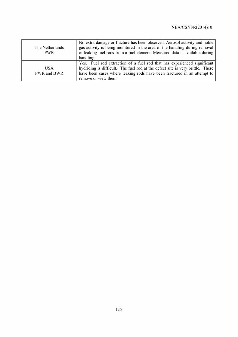
NEA/CSNI/R(2014)10
125
The Netherlands PWR
No extra damage or fracture has been observed. Aerosol activity and noble gas activity is being monitored in the area of the handling during removal of leaking fuel rods from a fuel element. Measured data is available during handling.
USA PWR and BWR
Yes. Fuel rod extraction of a fuel rod that has experienced significant hydriding is difficult. The fuel rod at the defect site is very brittle. There have been cases where leaking rods have been fractured in an attempt to remove or view them.
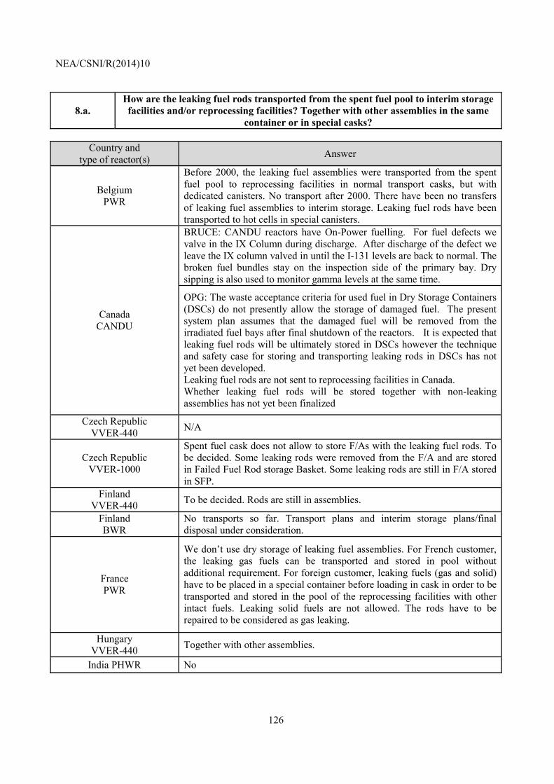
NEA/CSNI/R(2014)10
126
8.a. How are the leaking fuel rods transported from the spent fuel pool to interim storage facilities and/or reprocessing facilities? Together with other assemblies in the same
container or in special casks?
Country and type of reactor(s) Answer
Belgium PWR
Before 2000, the leaking fuel assemblies were transported from the spent fuel pool to reprocessing facilities in normal transport casks, but with dedicated canisters. No transport after 2000. There have been no transfers of leaking fuel assemblies to interim storage. Leaking fuel rods have been transported to hot cells in special canisters.
Canada CANDU
BRUCE: CANDU reactors have On-Power fuelling. For fuel defects we valve in the IX Column during discharge. After discharge of the defect we leave the IX column valved in until the I-131 levels are back to normal. The broken fuel bundles stay on the inspection side of the primary bay. Dry sipping is also used to monitor gamma levels at the same time.
OPG: The waste acceptance criteria for used fuel in Dry Storage Containers (DSCs) do not presently allow the storage of damaged fuel. The present system plan assumes that the damaged fuel will be removed from the irradiated fuel bays after final shutdown of the reactors. It is expected that leaking fuel rods will be ultimately stored in DSCs however the technique and safety case for storing and transporting leaking rods in DSCs has not yet been developed. Leaking fuel rods are not sent to reprocessing facilities in Canada. Whether leaking fuel rods will be stored together with non-leaking assemblies has not yet been finalized
Czech Republic VVER-440 N/A
Czech Republic VVER-1000
Spent fuel cask does not allow to store F/As with the leaking fuel rods. To be decided. Some leaking rods were removed from the F/A and are stored in Failed Fuel Rod storage Basket. Some leaking rods are still in F/A stored in SFP.
Finland VVER-440 To be decided. Rods are still in assemblies.
Finland BWR
No transports so far. Transport plans and interim storage plans/final disposal under consideration.
France PWR
We don’t use dry storage of leaking fuel assemblies. For French customer, the leaking gas fuels can be transported and stored in pool without additional requirement. For foreign customer, leaking fuels (gas and solid) have to be placed in a special container before loading in cask in order to be transported and stored in the pool of the reprocessing facilities with other intact fuels. Leaking solid fuels are not allowed. The rods have to be repaired to be considered as gas leaking.
Hungary VVER-440 Together with other assemblies.
India PHWR No
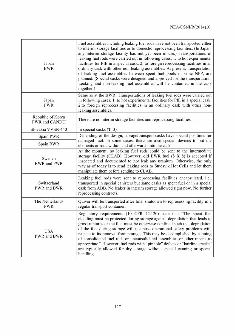
NEA/CSNI/R(2014)10
127
Japan BWR
Fuel assemblies including leaking fuel rods have not been transported either to interim storage facilities or to domestic reprocessing facilities. (In Japan, any interim storage facility has not yet been in use.) Transportations of leaking fuel rods were carried out in following cases, 1. to hot experimental facilities for PIE in a special cask, 2. to foreign reprocessing facilities in an ordinary cask with other non-leaking assemblies. At present, transportation of leaking fuel assemblies between spent fuel pools in same NPP, are planned. (Special casks were designed and approved for the transportation. Leaking and non-leaking fuel assemblies will be contained in the cask together.)
Japan PWR
Same as at the BWR. Transportations of leaking fuel rods were carried out in following cases, 1. to hot experimental facilities for PIE in a special cask, 2.to foreign reprocessing facilities in an ordinary cask with other non-leaking assemblies.
Republic of Korea PWR and CANDU There are no interim storage facilities and reprocessing facilities.
Slovakia VVER-440 In special casks (T13) Spain PWR Depending of the design, storage/transport casks have special positions for
damaged fuel. In some cases, there are also special devices to put the elements or rods within, and afterwards into the cask. Spain BWR
Sweden BWR and PWR
At the moment, no leaking fuel rods could be sent to the intermediate storage facility (CLAB). However, old BWR fuel (8 X 8) is accepted if inspected and documented to not leak any uranium. Otherwise, the only way as of today is to send leaking rods to Studsvik Hot Cells and let them manipulate them before sending to CLAB.
Switzerland PWR and BWR
Leaking fuel rods were sent to reprocessing facilities encapsulated, i.e., transported in special canisters but same casks as spent fuel or in a special cask from ABB. No leaker in interim storage allowed right now. No further reprocessing contracts.
The Netherlands PWR
Quiver will be transported after final shutdown to reprocessing facility in a regular transport container.
USA PWR and BWR
Regulatory requirements (10 CFR 72.120) state that “The spent fuel cladding must be protected during storage against degradation that leads to gross ruptures or the fuel must be otherwise confined such that degradation of the fuel during storage will not pose operational safety problems with respect to its removal from storage. This may be accomplished by canning of consolidated fuel rods or unconsolidated assemblies or other means as appropriate.” However, fuel rods with “pinhole” defects or “hairline cracks” are typically allowed for dry storage without special canning or special handling.
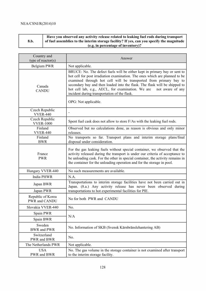
NEA/CSNI/R(2014)10
128
8.b. Have you observed any activity release related to leaking fuel rods during transport
of fuel assemblies to the interim storage facility? If yes, can you specify the magnitude (e.g. in percentage of inventory)?
Country and
type of reactor(s) Answer
Belgium PWR Not applicable.
Canada CANDU
BRUCE: No. The defect fuels will be either kept in primary bay or sent to hot cell for post irradiation examination. The ones which are planned to be examined through hot cell will be transported from primary bay to secondary bay and then loaded into the flask. The flask will be shipped to hot cell lab, e.g., AECL, for examination. We are not aware of any incident during transportation of the flask.
OPG: Not applicable.
Czech Republic VVER-440 -
Czech Republic VVER-1000 Spent fuel cask does not allow to store F/As with the leaking fuel rods.
Finland VVER-440
Observed but no calculations done, as reason is obvious and only minor releases.
Finland BWR
No transports so far. Transport plans and interim storage plans/final disposal under consideration.
France PWR
For the gas leaking fuels without special container, we observed that the activity released during the transport is under our criteria of acceptance to be unloading cask. For the other in special container, the activity remains in the container for the unloading operation and for the storage in pool.
Hungary VVER-440 No such measurements are available. India PHWR N.A.
Japan BWR Transportations to interim storage facilities have not been carried out in Japan. (8.a.) Any activity release has never been observed during transportations to hot experimental facilities for PIE. Japan PWR
Republic of Korea PWR and CANDU No for both PWR and CANDU
Slovakia VVER-440 No. Spain PWR
N/A Spain BWR
Sweden BWR and PWR No. Information of SKB (Svensk Kärnbränslehantering AB)
Switzerland PWR and BWR No.
The Netherlands PWR Not applicable. USA
PWR and BWR No. The gas volume in the storage container is not examined after transport to the interim storage facility.
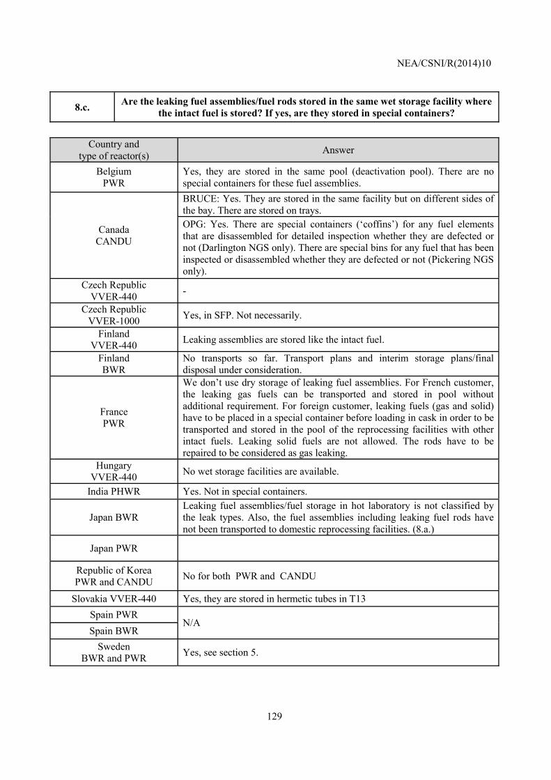
NEA/CSNI/R(2014)10
129
8.c. Are the leaking fuel assemblies/fuel rods stored in the same wet storage facility where the intact fuel is stored? If yes, are they stored in special containers?
Country and
type of reactor(s) Answer
Belgium PWR
Yes, they are stored in the same pool (deactivation pool). There are no special containers for these fuel assemblies.
Canada CANDU
BRUCE: Yes. They are stored in the same facility but on different sides of the bay. There are stored on trays. OPG: Yes. There are special containers (‘coffins’) for any fuel elements that are disassembled for detailed inspection whether they are defected or not (Darlington NGS only). There are special bins for any fuel that has been inspected or disassembled whether they are defected or not (Pickering NGS only).
Czech Republic VVER-440 -
Czech Republic VVER-1000 Yes, in SFP. Not necessarily.
Finland VVER-440 Leaking assemblies are stored like the intact fuel.
Finland BWR
No transports so far. Transport plans and interim storage plans/final disposal under consideration.
France PWR
We don’t use dry storage of leaking fuel assemblies. For French customer, the leaking gas fuels can be transported and stored in pool without additional requirement. For foreign customer, leaking fuels (gas and solid) have to be placed in a special container before loading in cask in order to be transported and stored in the pool of the reprocessing facilities with other intact fuels. Leaking solid fuels are not allowed. The rods have to be repaired to be considered as gas leaking.
Hungary VVER-440 No wet storage facilities are available.
India PHWR Yes. Not in special containers.
Japan BWR Leaking fuel assemblies/fuel storage in hot laboratory is not classified by the leak types. Also, the fuel assemblies including leaking fuel rods have not been transported to domestic reprocessing facilities. (8.a.)
Japan PWR
Republic of Korea PWR and CANDU No for both PWR and CANDU
Slovakia VVER-440 Yes, they are stored in hermetic tubes in T13 Spain PWR
N/A Spain BWR
Sweden BWR and PWR Yes, see section 5.
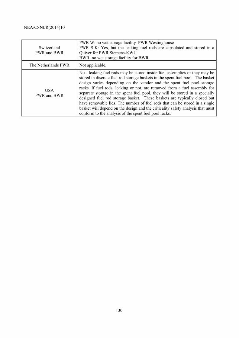
NEA/CSNI/R(2014)10
130
Switzerland PWR and BWR
PWR W: no wet storage facility PWR Westinghouse PWR S-K: Yes, but the leaking fuel rods are capsulated and stored in a Quiver for PWR Siemens-KWU BWR: no wet storage facility for BWR
The Netherlands PWR Not applicable.
USA PWR and BWR
No - leaking fuel rods may be stored inside fuel assemblies or they may be stored in discrete fuel rod storage baskets in the spent fuel pool. The basket design varies depending on the vendor and the spent fuel pool storage racks. If fuel rods, leaking or not, are removed from a fuel assembly for separate storage in the spent fuel pool, they will be stored in a specially designed fuel rod storage basket. These baskets are typically closed but have removable lids. The number of fuel rods that can be stored in a single basket will depend on the design and the criticality safety analysis that must conform to the analysis of the spent fuel pool racks.
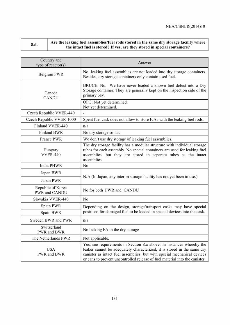
NEA/CSNI/R(2014)10
131
8.d. Are the leaking fuel assemblies/fuel rods stored in the same dry storage facility where the intact fuel is stored? If yes, are they stored in special containers?
Country and
type of reactor(s) Answer
Belgium PWR No, leaking fuel assemblies are not loaded into dry storage containers. Besides, dry storage containers only contain used fuel.
Canada CANDU
BRUCE: No. We have never loaded a known fuel defect into a Dry Storage container. They are generally kept on the inspection side of the primary bay.
OPG: Not yet determined. Not yet determined.
Czech Republic VVER-440 - Czech Republic VVER-1000 Spent fuel cask does not allow to store F/As with the leaking fuel rods.
Finland VVER-440 n/a Finland BWR No dry storage so far. France PWR We don’t use dry storage of leaking fuel assemblies.
Hungary VVER-440
The dry storage facility has a modular structure with individual storage tubes for each assembly. No special containers are used for leaking fuel assemblies, but they are stored in separate tubes as the intact assemblies.
India PHWR No
Japan BWR N/A (In Japan, any interim storage facility has not yet been in use.)
Japan PWR
Republic of Korea PWR and CANDU No for both PWR and CANDU
Slovakia VVER-440 No Spain PWR Depending on the design, storage/transport casks may have special
positions for damaged fuel to be loaded in special devices into the cask. Spain BWR
Sweden BWR and PWR n/a
Switzerland PWR and BWR No leaking FA in the dry storage
The Netherlands PWR Not applicable.
USA PWR and BWR
Yes, see requirements in Section 8.a above. In instances whereby the leaker cannot be adequately characterized, it is stored in the same dry canister as intact fuel assemblies, but with special mechanical devices or cans to prevent uncontrolled release of fuel material into the canister.
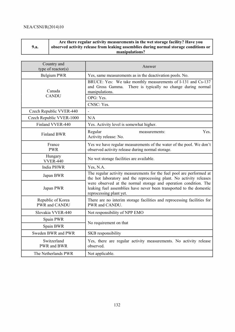
NEA/CSNI/R(2014)10
132
9.a. Are there regular activity measurements in the wet storage facility? Have you
observed activity release from leaking assemblies during normal storage conditions or manipulations?
Country and
type of reactor(s) Answer
Belgium PWR Yes, same measurements as in the deactivation pools. No.
Canada CANDU
BRUCE: Yes: We take monthly measurements of I-131 and Cs-137 and Gross Gamma. There is typically no change during normal manipulations. OPG: Yes. CNSC: Yes.
Czech Republic VVER-440 - Czech Republic VVER-1000 N/A
Finland VVER-440 Yes. Activity level is somewhat higher.
Finland BWR Regular measurements: Yes.Activity release: No.
France PWR
Yes we have regular measurements of the water of the pool. We don’t observed activity release during normal storage.
Hungary VVER-440 No wet storage facilities are available.
India PHWR Yes, N.A.
Japan BWR The regular activity measurements for the fuel pool are performed at the hot laboratory and the reprocessing plant. No activity releases were observed at the normal storage and operation condition. The leaking fuel assemblies have never been transported to the domestic reprocessing plant yet.
Japan PWR
Republic of Korea PWR and CANDU
There are no interim storage facilities and reprocessing facilities for PWR and CANDU.
Slovakia VVER-440 Not responsibility of NPP EMO Spain PWR
No requirement on that Spain BWR
Sweden BWR and PWR SKB responsibility
Switzerland PWR and BWR
Yes, there are regular activity measurements. No activity release observed.
The Netherlands PWR Not applicable.
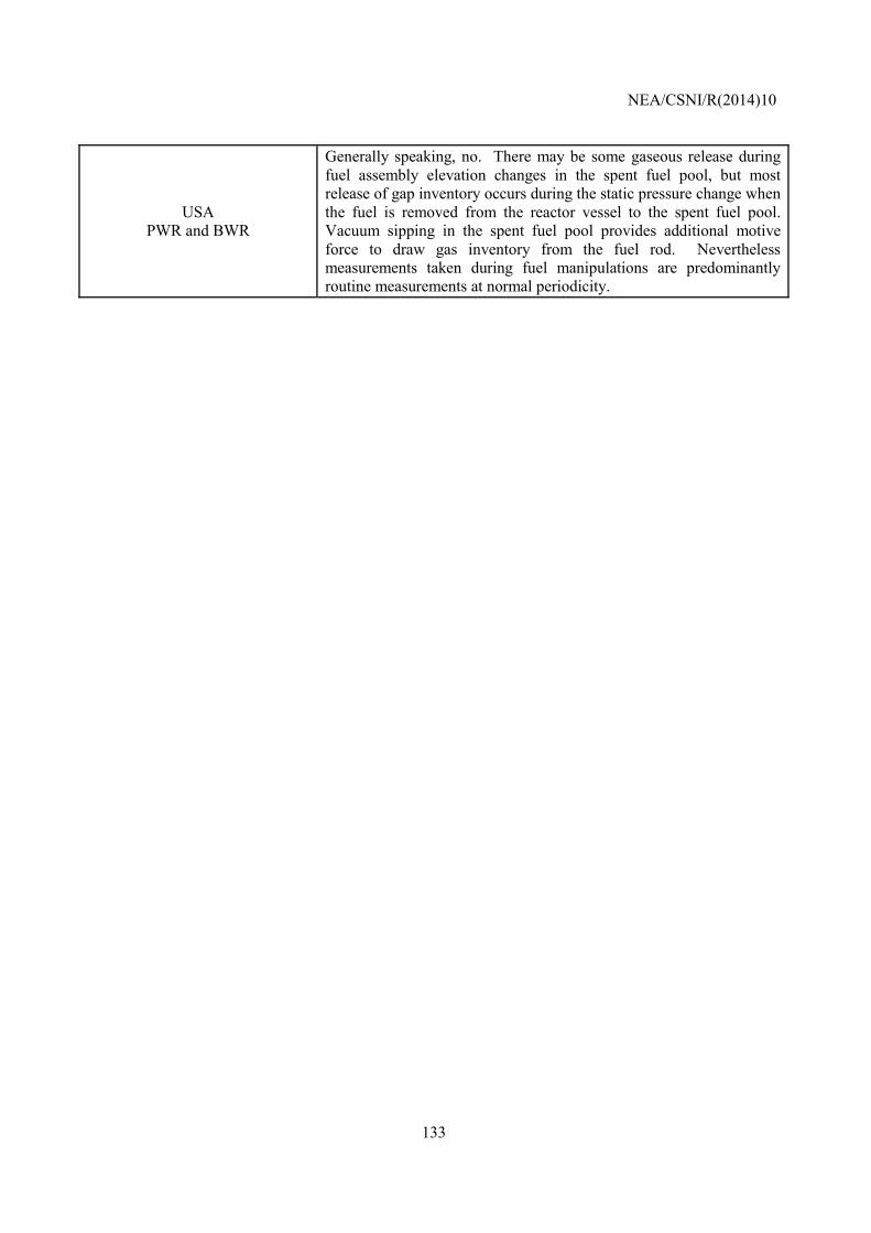
NEA/CSNI/R(2014)10
133
USA PWR and BWR
Generally speaking, no. There may be some gaseous release during fuel assembly elevation changes in the spent fuel pool, but most release of gap inventory occurs during the static pressure change when the fuel is removed from the reactor vessel to the spent fuel pool. Vacuum sipping in the spent fuel pool provides additional motive force to draw gas inventory from the fuel rod. Nevertheless measurements taken during fuel manipulations are predominantly routine measurements at normal periodicity.
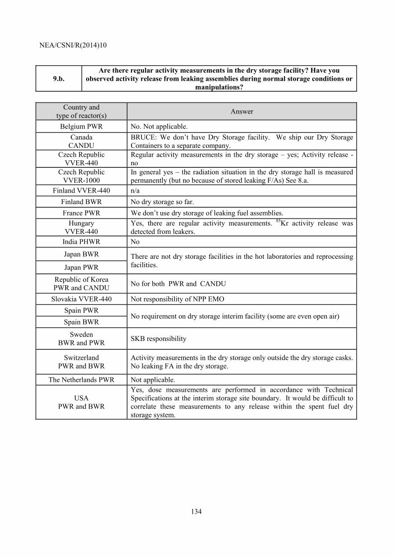
NEA/CSNI/R(2014)10
134
9.b. Are there regular activity measurements in the dry storage facility? Have you
observed activity release from leaking assemblies during normal storage conditions or manipulations?
Country and
type of reactor(s) Answer
Belgium PWR No. Not applicable. Canada
CANDU BRUCE: We don’t have Dry Storage facility. We ship our Dry Storage Containers to a separate company.
Czech Republic VVER-440
Regular activity measurements in the dry storage – yes; Activity release - no
Czech Republic VVER-1000
In general yes – the radiation situation in the dry storage hall is measured permanently (but no because of stored leaking F/As) See 8.a.
Finland VVER-440 n/a Finland BWR No dry storage so far. France PWR We don’t use dry storage of leaking fuel assemblies.
Hungary VVER-440
Yes, there are regular activity measurements. 85Kr activity release was detected from leakers.
India PHWR No
Japan BWR There are not dry storage facilities in the hot laboratories and reprocessing facilities. Japan PWR
Republic of Korea PWR and CANDU No for both PWR and CANDU
Slovakia VVER-440 Not responsibility of NPP EMO Spain PWR
No requirement on dry storage interim facility (some are even open air) Spain BWR
Sweden BWR and PWR SKB responsibility
Switzerland PWR and BWR
Activity measurements in the dry storage only outside the dry storage casks. No leaking FA in the dry storage.
The Netherlands PWR Not applicable.
USA PWR and BWR
Yes, dose measurements are performed in accordance with Technical Specifications at the interim storage site boundary. It would be difficult to correlate these measurements to any release within the spent fuel dry storage system.
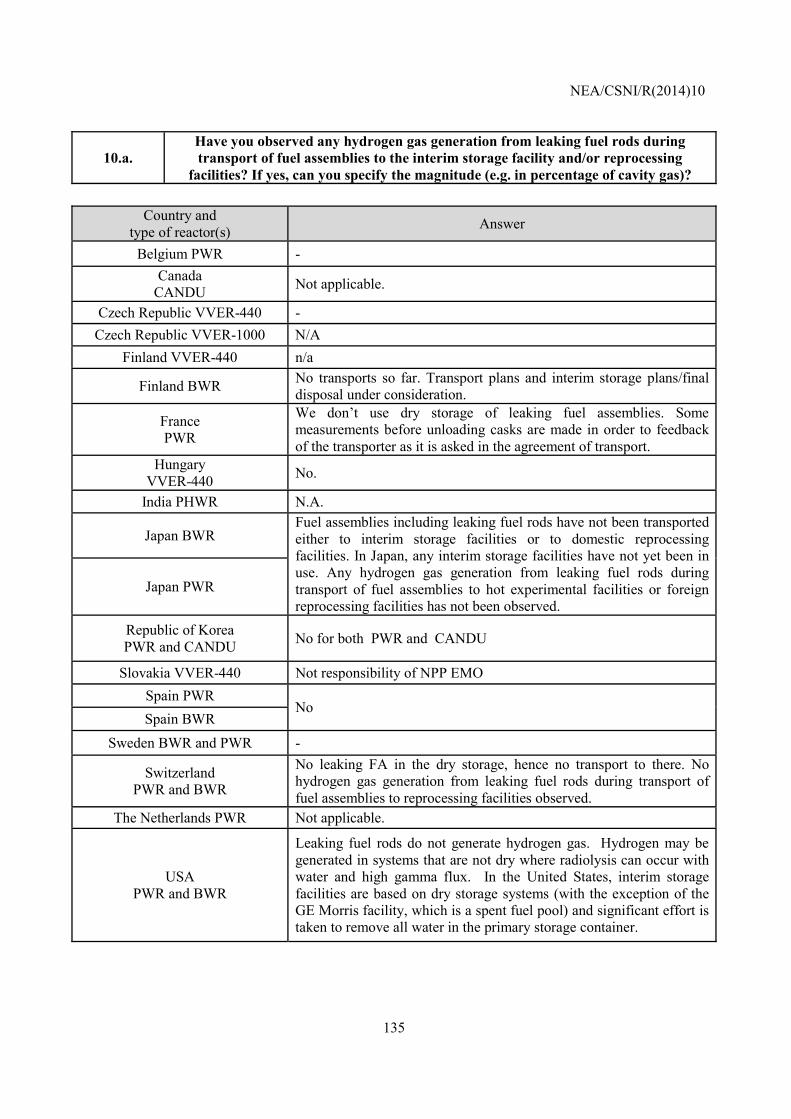
NEA/CSNI/R(2014)10
135
10.a. Have you observed any hydrogen gas generation from leaking fuel rods during transport of fuel assemblies to the interim storage facility and/or reprocessing
facilities? If yes, can you specify the magnitude (e.g. in percentage of cavity gas)?
Country and type of reactor(s) Answer
Belgium PWR - Canada
CANDU Not applicable.
Czech Republic VVER-440 - Czech Republic VVER-1000 N/A
Finland VVER-440 n/a
Finland BWR No transports so far. Transport plans and interim storage plans/final disposal under consideration.
France PWR
We don’t use dry storage of leaking fuel assemblies. Some measurements before unloading casks are made in order to feedback of the transporter as it is asked in the agreement of transport.
Hungary VVER-440 No.
India PHWR N.A.
Japan BWR Fuel assemblies including leaking fuel rods have not been transported either to interim storage facilities or to domestic reprocessing facilities. In Japan, any interim storage facilities have not yet been in use. Any hydrogen gas generation from leaking fuel rods during transport of fuel assemblies to hot experimental facilities or foreign reprocessing facilities has not been observed.
Japan PWR
Republic of Korea PWR and CANDU No for both PWR and CANDU
Slovakia VVER-440 Not responsibility of NPP EMO Spain PWR
No Spain BWR
Sweden BWR and PWR -
Switzerland PWR and BWR
No leaking FA in the dry storage, hence no transport to there. No hydrogen gas generation from leaking fuel rods during transport of fuel assemblies to reprocessing facilities observed.
The Netherlands PWR Not applicable.
USA PWR and BWR
Leaking fuel rods do not generate hydrogen gas. Hydrogen may be generated in systems that are not dry where radiolysis can occur with water and high gamma flux. In the United States, interim storage facilities are based on dry storage systems (with the exception of the GE Morris facility, which is a spent fuel pool) and significant effort is taken to remove all water in the primary storage container.
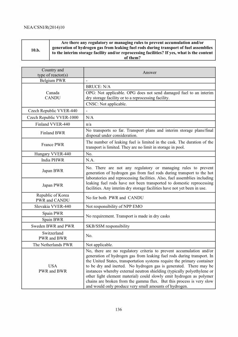
NEA/CSNI/R(2014)10
136
10.b.
Are there any regulatory or managing rules to prevent accumulation and/or generation of hydrogen gas from leaking fuel rods during transport of fuel assemblies to the interim storage facility and/or reprocessing facilities? If yes, what is the content
of them?
Country and type of reactor(s) Answer
Belgium PWR -
Canada CANDU
BRUCE: N/A OPG: Not applicable. OPG does not send damaged fuel to an interim dry storage facility or to a reprocessing facility. CNSC: Not applicable.
Czech Republic VVER-440 - Czech Republic VVER-1000 N/A
Finland VVER-440 n/a
Finland BWR No transports so far. Transport plans and interim storage plans/final disposal under consideration.
France PWR The number of leaking fuel is limited in the cask. The duration of the transport is limited. They are no limit in storage in pool.
Hungary VVER-440 No. India PHWR N.A.
Japan BWR No. There are not any regulatory or managing rules to prevent generation of hydrogen gas from fuel rods during transport to the hot laboratories and reprocessing facilities. Also, fuel assemblies including leaking fuel rods have not been transported to domestic reprocessing facilities. Any interim dry storage facilities have not yet been in use. Japan PWR
Republic of Korea PWR and CANDU No for both PWR and CANDU
Slovakia VVER-440 Not responsibility of NPP EMO Spain PWR No requirement. Transport is made in dry casks Spain BWR
Sweden BWR and PWR SKB/SSM responsibility Switzerland
PWR and BWR No.
The Netherlands PWR Not applicable.
USA PWR and BWR
No, there are no regulatory criteria to prevent accumulation and/or generation of hydrogen gas from leaking fuel rods during transport. In the United States, transportation systems require the primary container to be dry and inerted. No hydrogen gas is generated. There may be instances whereby external neutron shielding (typically polyethylene or other light element material) could slowly emit hydrogen as polymer chains are broken from the gamma flux. But this process is very slow and would only produce very small amounts of hydrogen.
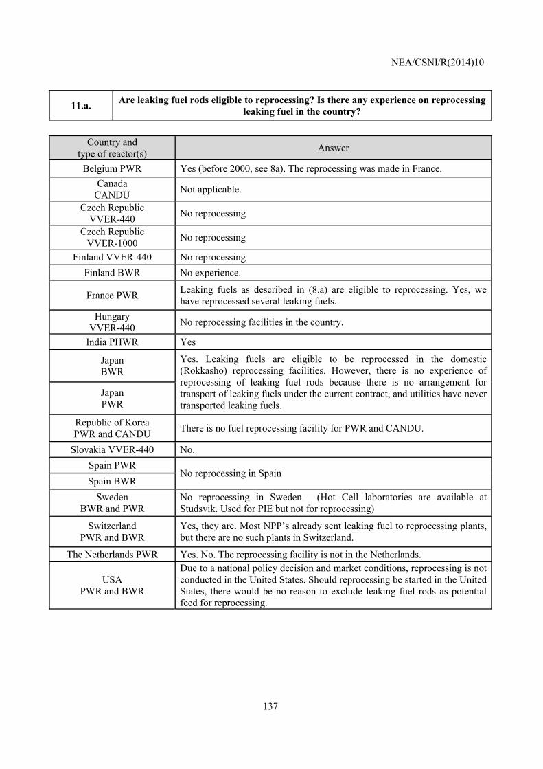
NEA/CSNI/R(2014)10
137
11.a. Are leaking fuel rods eligible to reprocessing? Is there any experience on reprocessing leaking fuel in the country?
Country and
type of reactor(s) Answer
Belgium PWR Yes (before 2000, see 8a). The reprocessing was made in France. Canada
CANDU Not applicable.
Czech Republic VVER-440 No reprocessing
Czech Republic VVER-1000 No reprocessing
Finland VVER-440 No reprocessing Finland BWR No experience.
France PWR Leaking fuels as described in (8.a) are eligible to reprocessing. Yes, we have reprocessed several leaking fuels.
Hungary VVER-440 No reprocessing facilities in the country.
India PHWR Yes
Japan BWR
Yes. Leaking fuels are eligible to be reprocessed in the domestic (Rokkasho) reprocessing facilities. However, there is no experience of reprocessing of leaking fuel rods because there is no arrangement for transport of leaking fuels under the current contract, and utilities have never transported leaking fuels.
Japan PWR
Republic of Korea PWR and CANDU There is no fuel reprocessing facility for PWR and CANDU.
Slovakia VVER-440 No. Spain PWR
No reprocessing in Spain Spain BWR
Sweden BWR and PWR
No reprocessing in Sweden. (Hot Cell laboratories are available at Studsvik. Used for PIE but not for reprocessing)
Switzerland PWR and BWR
Yes, they are. Most NPP’s already sent leaking fuel to reprocessing plants, but there are no such plants in Switzerland.
The Netherlands PWR Yes. No. The reprocessing facility is not in the Netherlands.
USA PWR and BWR
Due to a national policy decision and market conditions, reprocessing is not conducted in the United States. Should reprocessing be started in the United States, there would be no reason to exclude leaking fuel rods as potential feed for reprocessing.
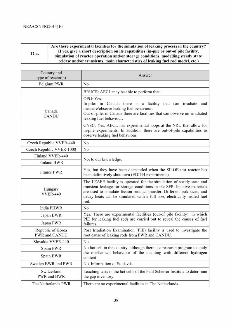
NEA/CSNI/R(2014)10
138
12.a.
Are there experimental facilities for the simulation of leaking process in the country? If yes, give a short description on its capabilities (in-pile or out-of pile facility,
simulation of reactor operation and/or storage conditions, modelling steady state release and/or transients, main characteristics of leaking fuel rod model, etc.)
Country and
type of reactor(s) Answer
Belgium PWR No.
Canada CANDU
BRUCE: AECL may be able to perform that. OPG: Yes. In-pile: in Canada there is a facility that can irradiate and measure/observe leaking fuel behaviour. Out-of-pile: in Canada there are facilities that can observe un-irradiated leaking fuel behaviour.
CNSC: Yes. AECL has experimental loops at the NRU that allow for in-pile experiments. In addition, there are out-of-pile capabilities to observe leaking fuel behaviour.
Czech Republic VVER-440 No Czech Republic VVER-1000 No
Finland VVER-440 Not to our knowledge.
Finland BWR
France PWR Yes, but they have been dismantled when the SILOE test reactor has been definitively shutdown (EDITH experiments).
Hungary VVER-440
The LEAFE facility is operated for the simulation of steady state and transient leakage for storage conditions in the SFP. Inactive materials are used to simulate fission product transfer. Different leak sizes, and decay heats can be simulated with a full size, electrically heated fuel rod.
India PHWR No
Japan BWR Yes. There are experimental facilities (out-of pile facility), in which PIE for leaking fuel rods are carried out to reveal the causes of fuel failures. Japan PWR
Republic of Korea PWR and CANDU
Post Irradiation Examination (PIE) facility is used to investigate the root cause of leaking rods from PWR and CANDU.
Slovakia VVER-440 No. Spain PWR No hot cell in the country, although there is a research program to study
the mechanical behaviour of the cladding with different hydrogen content Spain BWR
Sweden BWR and PWR No. Information of Studsvik.
Switzerland PWR and BWR
Leaching tests in the hot cells of the Paul Scherrer Institute to determine the gap inventory.
The Netherlands PWR There are no experimental facilities in The Netherlands.
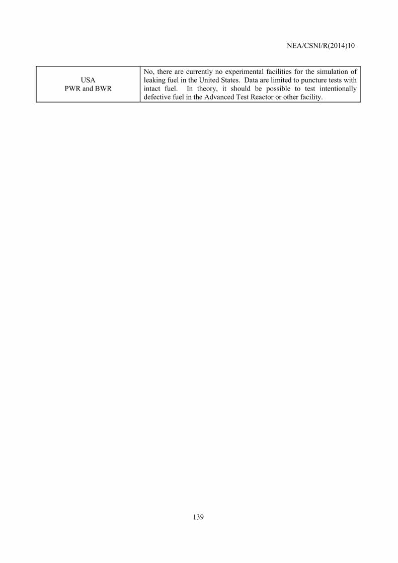
NEA/CSNI/R(2014)10
139
USA PWR and BWR
No, there are currently no experimental facilities for the simulation of leaking fuel in the United States. Data are limited to puncture tests with intact fuel. In theory, it should be possible to test intentionally defective fuel in the Advanced Test Reactor or other facility.
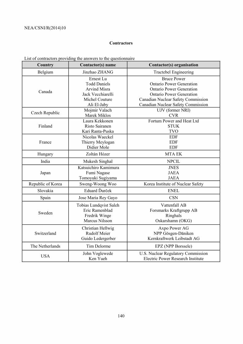
NEA/CSNI/R(2014)10
140
Contractors
List of contractors providing the answers to the questionnaire Country Contactor(s) name Contactor(s) organisation Belgium Jinzhao ZHANG Tractebel Engineering
Canada
Ernest Lu Todd Daniels Arvind Misra
Jack Vecchiarelli Michel Couture
Ali El-Jaby
Bruce Power Ontario Power Generation Ontario Power Generation Ontario Power Generation
Canadian Nuclear Safety Commission Canadian Nuclear Safety Commission
Czech Republic Mojmir Valach Marek Miklos
UJV (former NRI) CVR
Finland Laura Kekkonen Risto Sairanen
Kari Ranta-Puska
Fortum Power and Heat Ltd STUK TVO
France Nicolas Waeckel Thierry Meylogan
Didier Mole
EDF EDF EDF
Hungary Zoltán Hózer MTA EK India Mukesh Singhal NPCIL
Japan Katsuichiro Kamimura
Fumi Nagase Tomoyuki Sugiyama
JNES JAEA JAEA
Republic of Korea Sweng-Woong Woo Korea Institute of Nuclear Safety Slovakia Eduard Ďurček ENEL
Spain Jose Maria Rey Gayo CSN
Sweden
Tobias Lundqvist Saleh Eric Ramenblad Fredrik Winge Marcus Nilsson
Vattenfall AB Forsmarks Kraftgrupp AB
Ringhals Oskarshamn (OKG)
Switzerland Christian Hellwig
Rudolf Meier Guido Ledergerber
Axpo Power AG NPP Gösgen-Däniken
Kernkraftwerk Leibstadt AG
The Netherlands Tim Delorme EPZ (NPP Borssele)
USA John Voglewede Ken Yueh
U.S. Nuclear Regulatory Commission Electric Power Research Institute