learn more about these and other hydropro products by ... · expanding as a practical method of...
TRANSCRIPT

Corporate Headquarters Engineering & Manufacturing 6298 Camino Verde 2631 Highway J San Jose, CA 95119 Bourbon, MO 65441 Phone: (408) 281-7344 Phone: (573) 732-3318 Fax: (573) 732-9408
Hydraulic Tube Expansion coming of age
The worlds most reliable hydraulic tube expansion products
Learn more about these and other HydroPro products by visiting our website at www.hpro.com

Hydraulic tube expansion coming of Age Hydraulic expansion (uniform pressure expansion) has long been known and accepted for its many benefits to heat exchanger performance and longevity. These benefits include:
minimized metallurgical changes to the structural patterns of the tube material substantially reduced work hardening as compared to mechanical tube rolling the ability to expand any length expansion zone in a single step thereby eliminating step-rolling smooth transition from expanded-to-unexpanded tube zones
These benefits along with other forces, such as the acceptance by ASME and TEMA, have helped to legitimize this technology and have resulted in a preference for hydraulic tube expansion by many vessel fabricators and end users.
The early years of this technology were plagued by obstacles which inhibited the growth of hydraulic expanding as a practical method of expanding tube-to-tubesheet joints. Clumsy, high maintenance systems with bulky intensifiers; slow delivery of tooling and poor support were among the problems which prompted some users to shelve the technology in spite of its benefits. With HydroPro, these are problems .. no more
SYSTEMS are the most advanced hydraulic expansion systems available anywhere. Hardier high-pressure components with smart technology processors monitor the entire expansion process without the need for clumsy intensifiers found in other systems. HydroPro systems and tooling have been designed for production use and low maintenance.
TOOLING is designed for longer wear and more tube expansions than any other tooling available, with delivery of standard tooling in ten working days or less.
SUPPORT is unmatched. Hydraulic expansion is our business, and our commitment to this technology is without compromise. Whether your need is for systems, tooling or engineering support, we’re here to help with over 40 years of combined hydraulic expanding experience.
PRODUCT DEVELOPMENT is ongoing with focus on continuous improvement of existing equipment, along with development of new products and field services.
OTHER PRODUCTS include:TubePro systems for pre-expanding (locking) tubes into heat exchanger tubesheets prior to welding or final hard expanding
BoilerPro system for pre-expanding (locking) and flaring boiler tubes into drums prior to final hard expandingHydroProof high pressure tube testing and tube/tubesheet joint testing systems SleevePro hydraulic volume control sleeving systems and services HydroPlug hydraulic tube plugging services
Learn more about HydroPro products and services by visiting our website at www.hpro.com

HydroPro Expansion Mandrel Assembly
Corporate Headquarters 6298 Camino Verde
San Jose, CA 95119
Engineering & Manufacturing2631 Highway J
Bourbon, MO 65441
Sales Phone: (573) 732-3318
Fax: (573) 732-9408 Email: [email protected]
WORLD WIDE WEBwww.hpro.com
Hydraulic Tube Expansion .. Coming of age
HydroPro, Inc. presents ..
HydroPro hydraulic tube expansion systems.
Hydraulic expansion is the direct application of hydraulic pressure within a tube in order to form a tight joint between the tube and tubesheet in tubu-lar heat exchanger and boiler applications.
The HydroPro hydraulic tube expansion system is the result of more than twenty-five years of inno-vative high-pressure engineering and field experi-ence.
HydroPro systems are designed to expand tubes by directly applying high pressure hy-draulics (water) within a tube for the purpose of pro-ducing a tight tube-to-tubesheet joint within a pre-established expan-sion zone
other HydroPro products BoilerPro
TubePro
HydroProof
SleevePro
Locks boiler tubes into firm tube plate contact prior to full hydraulic, hybrid or roller expanding Locks exchanger tubes into tubesheet prior to welding. Consistently pre-sets tube end protrusion Hydro-test individual tubes and/or indi-vidual tube-to-tubesheet joints prior to full vessel hydro-test. An economical method of extending the service life of aging or failing heat ex-changers or condensers by hydraulically expanding sleeves (or ferrules) into ex-isitng tubes.

The mandrel is then mounted into the service gun and inserted into the first tube to be expanded.
Why expand tubes hydraulically?
Hydro-expanding produces a more desir-able metal structure than rolling. The metallurgical changes to the granular structural pattern of the tube material is more acceptable when produced by hy-dro-expanding than that produced by mechanical rolling.
Hydro-expanding produces joints with minimal residual stress and tube damage in the transition zone between the ex-panded and un-expanded regions of the tube, whereas mechanical rolling tends to produce a sharp transition with high residual stress. This residual stress can result in stress induced corrosion crack-ing once the unit enters service.
Hydro-expanding with HydroPro permits full depth expansion in one pass regard-less of tubesheet thickness.
Precise control of hydraulic pressure and dwell time from the HydroPro system console produces consistently repeat-able expansions from tube to tube.
How it works!
A HydroPro expansion mandrel assem-bly is selected for the tube size to be ex-panded.
The mandrel assembly consists of two high pressure seal assemblies mounted on a shaft designed to contain the ex-pansion pressure within the desired ex-pansion zone.
When the button on the service gun is depressed, water from the HydroPro system is pumped through the ser-vice gun and mandrel assem-bly into the pre-established ex-pansion zone.
The panel mounted LED readout allows the op-erator to follow each step of the expansion proc-ess as it occurs. Any failure to achieve expansion pressure or dwell time is identified (on the LED panel) with a red light at the point of failure.
Upon successful completion of the hydro-expanding cycle, the expan-sion mandrel is removed and in-serted into the next tube to be expanded. Total cycle time ap-proximately six seconds.
For more information contact:
HydroPro, Inc. Phone: (573) 732-3318
Fax: (573) 732-9408 Email: [email protected]


San Jose, California (Corp. Hqtrs) 408-281-7344 / Dareke, Colorado (Sales) 970-203-1079 Engineering & Manufacturing 2631 Highway J Bourbon, Missouri 65441 (Phone) 573-732-3318 (Fax) 573-732-9408
Hydraulic Expansion is the direct application of high internal hydraulic pressure within a tube in order to form a joint between a tube and tubesheet or parent tube. HydroPro products provide this expansive force in an accurately set, highly repeatable, and controlled manner.
HYDROPRO 6050
The HydroPro® 6050 is a state-of-the-art hydraulic expansion system designed for production use in even the most adverse conditions.
The system is an air driven hydraulic system capable of producing expansion pressures up to 60,000 psi (4,134 Bar).
Process/Troubleshooting Indicator Lights
track real-time expansion process.
Easy to read five digit digital display.
Data storage for up to 4,000 readings
standard.
Built-in “dolly” style enclosure with large
wheels for easy portability.
User sets high/low limits & expansion time.
HYDROPRO JR7
The HydroPro® JR-7 gives users a solidly built easy to use economical option for hydraulic tube expansion. All of the necessary functions for the majority of the industries tube expansion needs in one compact user friendly platform.
The system uses a proven air driven hydraulic systems capable of producing expansion pressures up to 50,000 psi (3,447 Bar).
Process/Troubleshooting
Indicator Lights track
real-time expansion
process.
Easy to read five digit
digital display.
Full electronic control
with pressure transducer.
Sturdy all metal enclosure
with large wheels for
easy portability.
Pre-set high/low limits &
expansion time.

TOOLING
Mandrel inserted in tube. (Static)
Low Pressure (Prefill).
High Pressure (Expansion).
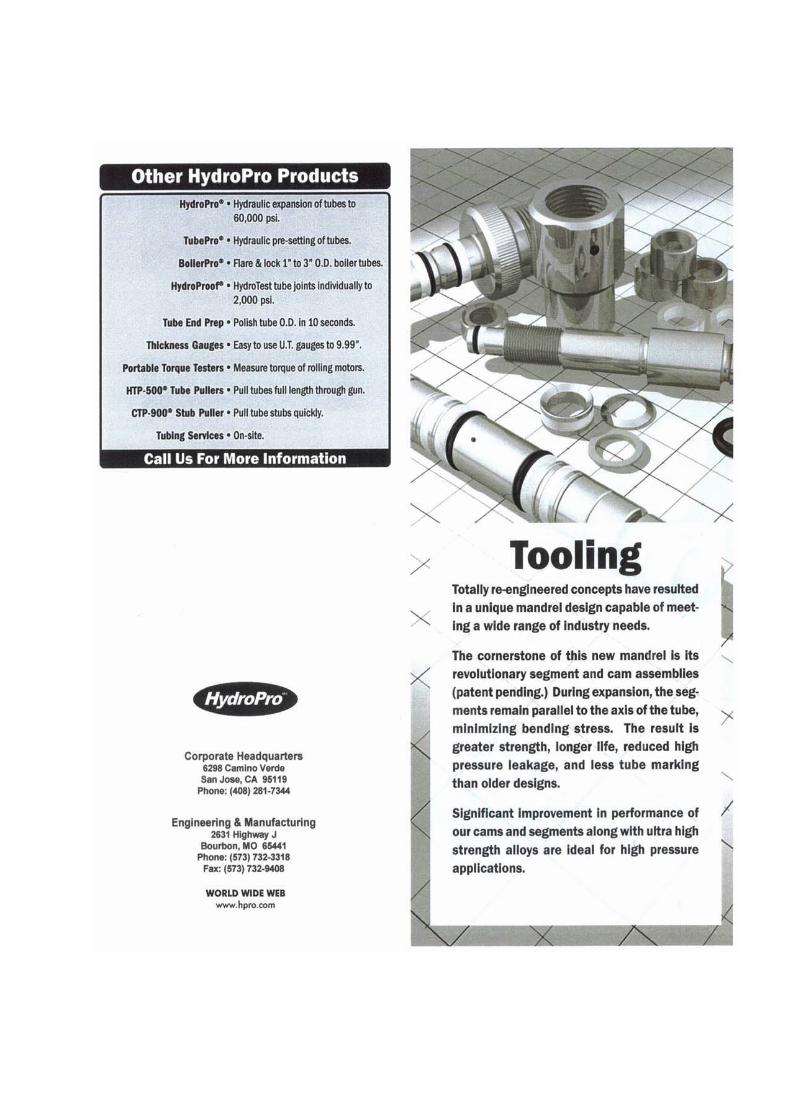
Totally re-engineered concepts have resulted in a unique mandrel design capable of meeting a wide range of industry needs.
The cornerstone of this new mandrel is its revolutionary segment and cam assemblies (patent pending). During expansion, the segments remain parallel to the axis of the tube, minimizing bending stress. The result is greater strength, longer life, reduced high-pressure leakage, and less tube marking than older designs.
Significant improvement in performance of our cams and segments along with ultra high strength alloys are ideal for high-pressure applications.
Interchangeability with older design products eliminates the need to scrap current mandrels and shafts. Expansion of a wider tube I.D. variation jumps traditional size gaps. Fast and easy band and segment replacement increases efficiency and ease of use. Standard sizes for tubes from ½” O.D. through 2 ½” O.D.
HydroPro Standard Tooling
.202” range between sizes. Heavy-duty cams resist bending. Parallel expanding segments reduce tube marking. 3/8” to 2 ½” standard. Standard 2-Week Delivery. All metal parts are high strength heat-treated alloy stainless steal.

Corporate Headquarters 6298 Camino Verde Dr. San Jose, CA 95119 Phone (408) 281-7344
World Leaders in Equipment and Technology for Hydraulic Tube Expansion
Engineering & Manufacturing 2631 Highway J
Bourbon, MO 65411 Phone (573) 732-3318
Fax (573) 732-9408
Page 1 of 7
MOST COMMONLY ASKED HYDRAULIC EXPANSION
QUESTIONS AND ANSWERS
QUESTIONS
1. HOW IS THE IDEAL PRESSURE FOR PRODUCTION USE DETERMINED? 2
2. WHAT IS THE PERMISSIBLE VARIATION FROM EXPANSION PRESURE? 2
3. WHAT ARE THE EFFECTS OF EXCEEDING THE EXPANSION PRESSURE RANGE? 3
4. FOR WHAT TIME PERIOD IS THE PRESSURE HELD? 3
5. THE INTERFACIAL PRESSURE BETWEEN TUBE AND TUBESHEET WITH PRESSURE
APPLIED. 3
6. THE RESIDUAL INTERFACIAL FIT PRESSURE REMAINING AFTER EXPANSION PRESSURE
IS REMOVED 3
7. DIAMETRICAL CLEARANCE BETWEEN TUBE AND TUBESHEET? 4
8. WHAT IS THE EFFECT OF TUBESHEET SURFACE PROFILE AND GROOVES? 4
9. EFFECT OF RESPECTIVE PHYSICAL PROPERTIES OF TUBE AND TUBESHEET? 4
10. WHAT ARE LIMITATIONS OF LIGAMENT AND TUBE WALL THICKNESSES? 5
11. WHAT IS CORRECTIVE ACTION FOR JOINT LEAK AND LIMITATIONS ON EXPANSION
PRESSURE? 5
12. CAN HYDROPRO MEET MILITARY SPEC REQUIREMENT OF A PULL-OUT STRENGTH
EQUAL TO TUBE YIELD? 5
13. WHAT IS THE FUNCTION AND SPEED OF THE TUBEPRO TUBE SETTING TOOL? 5
14. WHAT ARE SPECIAL CONSIDERATIONS WHEN USING MANDRELS? 5
15. WHAT ARE THE “PRE” PREPARATIONS TO HYDRAULIC EXPANSION? 6
16. TUBE EXPANSION BEFORE WELDING. 6
17. TUBE EXPANSION AFTER WELDING 6
18. WHAT IS THE EFFECT OF THE WELD BEAD? 7
19. IS THE COST OF THE HYDROPRO SYSTEM MUCH MORE THAN MECHANICAL ROLLING 7

MOST COMMONLY ASKED HYDRAULIC EXPANSION QUESTIONS AND ANSWERS (con’t)
Page 2 of 7
1. HOW IS THE IDEAL PRESSURE FOR PRODUCTION USE DETERMINED?
The ideal expanding pressure is theoretically determined first from equations and tables based upon the curve published in “Hydro expanding; the Current State of Art” presented at the Joint power General Conference in October 1982. The curve was adopted from, Goodier, J.N. & Schoessow, G.J., “The Holding Power and Hydraulic Tightness of Expanded Tube Joints: Analysis of the Stress and Deformation”, Trans. ASME July 1943.
It provides the theoretically highest expanding pressure that will: (1) not exceed the plastic limit of the tube at its inside; and (2) will not cause the pressure of the tube on the hole to exceed the plastic limit of the tubesheet hole. In the Goodier & Schoessow work, it was demonstrated that the highest expanding pressure that met these conditions would produce the maximum interfacial fit pressure. It was also demonstrated that this was the pressure that would produce the highest residual interfacial pressure when expanding pressure was released.
It is extremely important to note that the expanding pressure chosen from the chart must be related to the actualmill test values of the tube and tubesheet yield shown on mill test reports. Specifically, it should be pointed out that there may be a wide variation in tube yields from heat to heat, and the minimum values shown in the ASME code cannot be used for setting expanding pressures. Suggest that they maintain a tube map showing where tubes from each heat are located.
Empirical determination through tests and the use of coupons covers items not considered in the theoretical approach:
A. Tube spring back varies with different tube material. Titanium is the worst, showing about .004” spring back or relaxation when pressure is released. This degree of spring back is not available in the published data on material properties such as tensile, yield, elongation, modulus, etc. It must be considered that hydraulic expanding, unlike roller expanding, DOES NOT mechanically work harden the tube; therefore, the tube should be deflected sufficiently to overcome spring back. Work hardening does tend to overcome spring back. The various deleterious effects of this are well known in the industry.
B. Effect of grooves upon sealing and pull strength are best determined by coupon tests.
C. Effect of variations in surface conditions of tube O.D. and tubesheet hole cannot be calculated and one needs to resort to empirical findings.
Report HAR114, Appendix, shows a typical test program on a particular tube and tubesheet combination. Through a test such as this, the following can be determined:
1) Tube O.D. change vs. pressure, including spring back characteristics. 2) O.D. change of tube and coupon or portion of tubesheet overcome tube which determines
pressure needed to overcome tube spring back characteristics. 3) Groove width and depth effect on penetration of tube and ability to cut through tube O.D.
surface discontinuities. It also shows amount of shear shoulder which produces pull strength. This data is evaluated against 1) and 2) above and the optimum groove configuration determined.
2. WHAT IS THE PERMISSIBLE VARIATION FROM EXPANSION PRESSURE (+OR-)?
Expansion pressure should be held as close as possible. With the HydroPro, a +/- of 1000 psi is easily held. The controller set points and indicating lights give the operator good control of the swaging process. This is in stark contrast to the lack of control with roller expansion which is dependent upon operator “feel” and skill. Furthermore, the HydroPro performance can be accurately measured and recorded.
It should be noted, that the variation from set pressure on the HydroPro system is well within the limits of precision of data on the tube and tubesheet properties.

MOST COMMONLY ASKED HYDRAULIC EXPANSION QUESTIONS AND ANSWERS (con’t)
Page 3 of 7
3. WHAT ARE THE EFFECTS OF EXCEEDING THE EXPANSION PRESSURE RANGE?
The effects of exceeding the maximum theoretical pressure are to initiate tube or tubesheet extrusion. The actual degree can be determined by calculation or review of test data. It can also reduce leakage and increase joint strength. This is in contrast to roller expansion, where over rolling will break the bond between tube and tubesheet, increase leakage and reduce joint strength.
An under pressure condition will reduce joint strength and increase the tendency to leak. This can be corrected by re-expanding at a higher pressure.
4. FOR WHAT TIME PERIOD IS THE PRESSURE HELD?
There are two adjustable time periods:
a) Prefill Time: This is the time to fill the tube at low pressure and is determined by the diameter and length of tube being pressurized. Time can be determined by observing the time it takes for the pressure to stabilize.
b) Expansion Time: This is the expansion pressure holding time. This time can be determined by observing the pressure read-out. It can also be observed more scientifically by attaching a strip chart recorder and observing the profile of the pressure trace.
5. THE INTERFACIAL PRESSURE BETWEEN TUBE AND TUBESHEET WITH EXPANSION PRESSURE APPLIED.
No attempt is made to idealize interfacial pressure during application of expanding pressure. Based upon the Goodier & Schoessow work, maximum expanding pressure is applied that will not cause extrusion of tube or tubesheet. This will provide the highest residual interfacial fit pressure when the expanding pressure is withdrawn.
The original Goodier & Schoessow paper, can be used to determine the stress state of the tube-tubesheet structure under various pressure load conditions. Podhorsky & Krips’ papers provide a theoretical consideration which gives results somewhat different from the Goodier & Schoessow investigation, Uragami, K. Sugino, M. Urushibatat, S. Kodama, and Jujiwara’s, “Experimental Residual Stress Analysis Of Tube To Tube Sheet Joints During Expansion”, ASME paper 82-PV-61, give other results.
Since the interfacial pressure during application of pressure is not idealized, permissible variations have not been established. The variation in interfacial fit pressure during application of expanding pressure will essentially vary linearly with the limits of variation of the HydroPro set pressure which is + or – 1000 psi. There is no way directly to measure the variations in interfacial pressure during or after expanding.
If the expanding pressure, that will produce the maximum residual interfacial pressure after expanding pressure is released, is exceeded, it may cause either the tube or the tube hole to extrude.
If the tubesheet extrudes, it will distort! When this happens, joint strength declines.
6. THE RESIDUAL INTERFACIAL FIT PRESSURE REMAINING AFTER EXPANSION PRESSURE IS REMOVED.
Theoretical calculations for residual pressure can be made by using Soler-Xu Hong work, embodied in chapter 7 of Soler, A.I. and Singh, K.P., “Mechanical Design of Heat Exchangers and Pressure Vessels”, Arcturus Publishers, Inc., Cherry Hill, NJ, 1984. This work provides in Appendix 7.D, the computer code for calculating residual fit pressure among other things.
However, the theoretical calculations notwithstanding. Relying on theoretical joint strength calculations using anyexpanding method is not recommended. Instead, test models should be made and pullout results should be correlated with expanding pressure.

MOST COMMONLY ASKED HYDRAULIC EXPANSION QUESTIONS AND ANSWERS (con’t)
Page 4 of 7
Consider this—the interfacial pressure is but one of three major factors in determining joint strength and tightness. The other factors are surface area in contact and effective coefficient of friction. You can make an approximate calculation of area in contact, but unless you can control both tube surface and hole surface within narrow limits, you cannot truly predict the coefficient of friction that exists in any tube-tubesheet assembly. In addition, the coefficient of friction will vary from hole to hole depending upon the variations in machining.
When the idealized residual pressure is exceeded, the joint strength declines. This relationship is illustrated in the work by Goodier and Schoessow.
7. DIAMETRICAL CLEARANCE BETWEEN TUBE AND TUBESHEET?
Ideally, there would be no clearance between the tube and tubesheet hole when expanding pressure is applied. As a general rule, the smaller the clearance, the better from the expanding point of view no matter what expanding method is used. What establishes the clearance used by manufacturers is their ability to stuff the tubes through the tubesheets and baffles. This varies with the size of the structure, its configuration and the tube diameter.
From a practical standpoint, the best quality will be obtained by using the TEMA Special Close Fit drilling tolerances and adhering to tubing manufactured in complete conformity with section II of the ASME code.
8. WHAT IS EFFECT OF TUBESHEET SURFACE PROFILE AND GROOVES?
Circumferential markings are beneficial and will indent themselves into the tube O.D. surface. This will increase joint strength and reduce leakage. Longitudinal markings form leak paths and increase leakage. It is therefore recommended, that the tubesheet holes be drilled only with no reaming afterward.
Grooves are recommended and serve to interrupt longitudinal markings, thus providing a seal. Various investigators have examined the effects grooves on strength and tightness, both for roller expanded and hydraulically expanded tube configurations. Specifically, joint strength increases linearly with groove depth. The minimum effective groove depth for hydraulic expansion was shown by Yoshitomi, and others, “Tube-Hole Structure For Expanded Tube-To-Tubesheet Joints”, U.S. Patent No. 4,142,581, to be about 1/64”.
Generally groove dimensions are approximately 2-1/2 times wall thickness in width with a depth of approximately 20% times wall thickness. Final dimensional determination can be further optimized by test.
Out of round and tapered holes (within reason) are easily handled as pressure is equal in all directions and the tube will form itself to the I.D. of the hole.
9. EFFECT OF RESPECTIVE PHYSICAL PROPERTIES OF TUBE AND TUBESHEET?
Generally speaking, the tubesheet should be stronger than the tube. With hydraulic expansion, the tube is deformed until it contacts the tubesheet. The tubesheet is then deflected within its elastic range sufficiently so that, when expanding pressure is released, the tubesheet relaxes and creates an interference fit with the tube O.D.
Specifically: It is always preferable to have the tubesheet yield strength higher than the tube yield strength.
It is always preferable to have the tubesheet modulus of elasticity lower than the tube modulus so that the tube hole will spring back more than the tube.
It is always preferable to have a harder hole than tube. According to the Goodier & Schoessow analysis, “no joint can be made if the tube is much harder than the plate, unless the tube is sufficiently thick.”
If the tubesheet yield is less than 60% of the tube yield, it is problematical whether you can get a satisfactory expanded joint, no matter how you expand it. If the tube modulus of elasticity is very low and the tube yield stress very high compared with relatively high tubesheet elastic modulus and low tubesheet yield stress, satisfactorily tight, a strong expanded joint made by any process will be difficult to achieve and may not be achieved. This is especially true when the ratio of tube diameter to wall is greater than 20 (thin walled tubes).

MOST COMMONLY ASKED HYDRAULIC EXPANSION QUESTIONS AND ANSWERS (con’t)
Page 5 of 7
10. WHAT ARE LIMITATIONS OF LIGAMENT AND TUBE WALL THICKNESS?
The relationship between tube wall and ligament thickness is a design consideration. There is an infinite number of combinations. Each combination requires its own evaluation and no general answer is available.
Wall thickness by itself doesn’t determine its expandability. The relationship between wall thickness and tube O.D., along with its tensile strength, determines how much pressure a tube will withstand. Therefore, since hydro expanding does not apply force cyclically but only by uniformly applied pressure, any tube-ligament configuration that can be successfully rolled should be more capable of being successfully hydro expanded. Generally, it has been found that hydraulic pressure is approximately2-1/2 times the calculated tube burst pressure.
Variations in wall thickness do not limit the effectiveness of HydroPro.
The position of the tube hole relative to the center edge or corner of the tubesheet doesn’t limit the effectiveness of HydroPro. It may, however, affect the deflection characteristics of the ligaments.
11. WHAT IS THE CORRECTIVE ACTION FOR JOINT LEAK AND LIMITATIONS ON EXPANSION PRESSURE?
Any joint can be re-expanded at the same or a higher pressure. In some cases, a short tack roll (Hybrid) can be added if kept well inside the tubesheet. This would utilize the tighter fit produced by the roller work hardening without it extending into the transition zone.
The HydroPro system is set at the factory for a maximum swage pressure of 60,000 psi. This can be increased, but it is not generally recommended.
12. CAN HYDROPRO MEET MILITARY SPEC REQUIREMENT OF A PULL OUT STRENGTH EQUAL TO TUBE YIELD STRENGTH?
This can be accomplished with the use of properly designed grooves. The joint strength is determined by the shearing strength of the expanded portion of the tube within the groove.
13. WHAT IS FUNCTION AND SPEED OF TUBEPRO TUBE SET TOOL?
The TubePro tube setting tool serves to position the tube relative to tubesheet face. It also opens the diameter of the tube and makes it easier to insert the mandrel o-rings into the tube. The normal time to position the tube and set it in is 3 to 5 seconds.
14. WHAT ARE SPECIAL CONSIDERATIONS WHEN USING MANDRELS?
Mandrels come in ½ mm increments. O-Rings, to be effective, must have squeeze within the tube I.D. The amount of squeeze is carefully worked out within the ½ mm increment sizing.
Tube ends should be chamfered on the I.D. to permit easy o-ring insertion.
O-Ring seal life is not usually determined by condition of tube entrance. It is not unusual to get 200 to 500 or more expansions per o-ring.
The o-ring is 75 Shore A hardness and will seal most tube I.D. conditions.
The o-ring doesn’t function alone. It is supported by a Shore D polyurethane backup ring which is in turn supported by a six piece steel segment. These are designed to support pressures up to 60,000 psi.
There is scant likelihood of a tube rupture as long as the pressure zone is within the tubesheet.
Normal production rate is determines by dwell times and speed of operator inserting and removing tooling, 3 to 5 seconds is very common on most tube to tubesheet jobs.

MOST COMMONLY ASKED HYDRAULIC EXPANSION QUESTIONS AND ANSWERS (con’t)
Page 6 of 7
15. WHAT ARE THE “PRE” PREPARATIONS TO HYDRAULIC EXPANSION?
Measure and mike tube I.D.’s for proper mandrel selection. (Refer to mandrel sizing chart in tooling handbook.)
Make sure tubes are clean and I.D. of tubes are properly chamfered for easy insertion of mandrel and tube lock.
Measure and mike I.D. of tubesheet hole for accurate expansion zone. Also be alert for exact depth of chamfer in tubesheet hole, if applicable. Example: T/S hole thickness is 7/8”. Expansion zone is normally ¾” (1/8” & 1/8”). If there is a chamfer of 1/32”, that makes the placement of the mandrel inside the tubesheet necessary to be 1/32” more inside. The danger, if not done, is blown segments and o-rings, as well as loss of seal.
Always check expansion pressure for desired job. Please refer to pressure setting chart and please feel free to contact HydroPro, Inc. for confirmation of recommended pressure settings as well as time settings.
If you have sized the mandrel for said tube and tubesheet job and after mandrel insertion you find that you can’t achieve a seal, go to the next largest o-ring size.
Always use a liberal amount of lubricant with both the tube set tool as well as the expanding mandrel. Recommended lubricant: HSL-102, conforms to MIL-D-16791-ETYL.
When sizing the tube set tool, drawbar and anvil, always down size by ½ mm (or size), i.e.: proper size should be 1550, go down to 1500 on tube set.
Always refer to operating manual on HydroPro before starting a job and always feel to contact HydroPro, Inc. or your local Representative for advice.
16. TUBE EXPANSION BEFORE WELDING.
Welding after Hydraulic Expansion may leave difficulties with the out flow of weld gases. There are numerous reports and studies that indicate the negative effects of welding gases that were not allowed to escape. For this reason, we recommend the use of a tube set tool to position and set the tube prior to welding. This process allows the welding gases to escape.
Distilled or purified water is used, as this is preferred by most manufacturers. Any other fluid must be suitable for use in the pumping system. Acetone is not a suitable fluid.
17. TUBE EXPANSION AFTER WELDING.
There ought not be any weld roll-over welding. The shop personnel should be instructed to run a cleaning reamer into the tube.
After welding, the welded surfaces should be fluid penetrant examined. When all welds are shown to be joint tested by an air-bubble test; depending upon how critical the welded joint is, a halogen or a helium leak test may be considered. Only after the weld is shown to be tight should you expand. After expanding, the standard hydrostatic test is used to verify that the structure can withstand the stresses imposed by applying pressure of 1.5 X the maximum allowable pressure shown on the nameplate, corrected for temperature.
If the expanded, zone started about 3/8” into the tube interior behind the weld, the expansion would not affect the weld at all, except to protect if from the effects of tube vibration. If expansion were to start right at the welded region, the weld would be stressed uniformly and have a slight tendency to work the weld. However, it is doubted that enough force would be applied to achieve the benefit of changing its character from a cast structure to a forged grain structure.

MOST COMMONLY ASKED HYDRAULIC EXPANSION QUESTIONS AND ANSWERS (con’t)
Page 7 of 7
18. WHAT IS EFFECT OF WELD BEAD INSIDE THE TUBE DIAMETER?
The weld bead affects the size of mandrel that can be inserted into the tube. A limited size weld bead can be sealed by the o-ring. Usually, the tube is drawn after welding, in which case there is no weld bead and thus no effect from it.
Expanded joints can be tested by any means previously used by the manufacturer. Leak test fixtures are available for leak testing individual tube stubs.
19. IS THE COST OF THE HYDROPRO MUCH MORE EXPENSIVE THAN MECHANICAL ROLLING?
In the past HydroPro, Inc. has only been able to offer one Hydraulic System. We now have a Base HydroPro System that is approximately one-half the cost. This system still allows you the ability to hydraulically expand, without the digital electronics. The +/- pressure is till 1000 psi and you will still be able to expand in a production mode. After the initial capital outlay for the equipment, the tooling and spares required for each succeeding job are less costly than mechanical rolling methods. In addition to the Base HydroPro System HydroPro, Inc. also offers a 6050 digital system and a 7000 nuclear grade system. Each of these systems will address any of your expanding needs.
HydroPro, Inc. 2631 Highway J
Bourbon, MO 65441 573-732-3318
FAX: 573-732-9408

Corporate Headquarters 6298 Camino Verde Drive San Jose, CA 95119 Phone (408) 281-7344
World Leaders in Equipment and Technology for Hydraulic Tube Expansion
Engineering & Manufacturing 2631 Highway J
Bourbon, MO 65441 Phone (573) 732-3318
Fax (573) 732-9408
HYDRAULIC EXPANSION DATA SHEET DATE CONTACT PHONE
HYDRAULIC EXPANSION END USER
SCOPE OF APPLICATION AND SPECIFICATIONS NEW OR RETUBE NUMBER OF EXPANSIONS APPROXIMATE START DATE
TYPE OF UNIT: o Heat Exchanger o Condenser o Feedwater Heater
o Boiler o Other (Describe):
TUBESMATERIAL MIN. YIELD MIN. TENSILE
O.D. WALL THICKNESS/GAGE WALL (CIRCLE ONE): Avg. / Min. / Nominal ACTUAL TUBE I.D. MEASUREMENT TYPE: Seamless / Welded DrawnU-BEND OR STRAIGHT OVERALL LENGTH OF TUBE
SETTING OF TUBE TO TUBESHEET PRIMARY FACE: Recessed / Flush / ProtrudingMAX. PROTRUSION OF TUBE ON SECONDARY TUBESHEET
ARE THE TUBES TO BE WELDED TO THE TUBESHEET: Yes / No HAVE TUBES BEEN PROPERLY ANNEALED: Yes / No
TUBESHEETTOTAL THICKNESS MATERIAL MIN. YIELD MIN. TENSILE
CLAD: Yes / No THICKNESS MATERIAL
SHELL ATTACHED: Yes / No PARTITION PLATE: Yes / NoIF "YES" TO EITHER OF THE ABOVE: SHORTEST DISTANCE BETWEEN HOLE CENTER LINE AND SHELL/PLATE
HOLESDIAMETER CHAMFER: Yes / No WHERE IS THE CHAMFER LOCATED: Face / BackDEGREE OF CHAMFER DEPTH OF THE CHAMFER
GROOVESNUMBER Note: as a minimum, placement of the 1st groove should begin 1/2" from the face of the tubesheet or in the center based on tubesheet thickness.
TEMA: Yes / No IF "NO", PLEASE PROVIDE SPECIFICATIONS IN THE AREA PROVIDED ON PAGE 2.
CUSTOMER RECEPTIVE TO HYDRAULIC EXPANSION GROOVE: Yes / No Note: hydraulic expansion groove is a single wide groove (centered in sheet if possible).
LIGAMENTTHICKNESS PITCH HOLE PATTERN

HYDRAULIC EXPANSION DATA SHEET (CON’T)
2 of 2
EXPANSION ZONE START OF EXPANSION INSIDE TUBESHEET
STOP OF EXPANSION DISTANCE FROM REAR OF TUBESHEET
TOTAL EXPANSION ZONE
TUBE-TO-TUBESHEET WELD REQUIREMENTS ARE TUBES TO BE WELDED: Yes / No IF "YES": Seal Welded / Strength WeldedWILL YOU TUBE LOCK PRIOR TO WELD: Yes / NoWHAT IS THE MAXIMUM COUNTER SINK O.D. FOR WELD
EXPANDING PRESSURE REQUIREMENTS CONTACT ONLY: Yes / No HYDROTEST PRESSURE APPROXIMATE START DATE
NOTE: WHEN WELDING, THE FOLLOWING EXPANSION PROCEDURE IS RECOMMENDED.
1. TubePro; setting of tube 2. Weld
3. Hydraulic Expand Note: No weld rollover is recommended when hydraulic expanding
SPECIFICATIONS (IF APPLICABLE)
Please provide any available drawings, sketches, or blueprints, as well as performance requirements regarding working and test pressure of the vessel. Drawings Supplied: Yes / No
EXTERNAL EXTENSIONS For expansion which require going around an interference such as a channel, shell, partition plate, or any other obstruction, creating a situation where expansion would take place at a distance from the tubesheet face.
DISTANCE FROM OUTSIDE FACE OF SHELL OR PLATE TO FACE OF TUBESHEET
IS THERE ACCESS FOR A STOP COLLAR TO BE LOCATED AT TUBESHEET FACE OR OUTSIDE OF SHELL: Yes / No
INTERNAL EXTENSIONS For expansions which require mandrel travel within a tube, re: inner tubesheet of a dual tubesheet application, baffle expansions, or expansion of a tubesheet through the opposite end.
DISTANCE FROM TUBESHEET FACE TO FACE OF INNER TUBESHEET OR BAFFLE.
Signature: ______________________________________________________________ Date:___________