learning guide j-1 install fire alarm and suppression systems · constru ction electrician...
TRANSCRIPT

ConstruCtion ElECtriCian apprEntiCEship programlevel 4 line J: install signal and Communication systems
lEarning guidE J-1install firE alarm and supprEssion systEms
J-1

ForewordThe Industry Training Authority (ITA) is pleased to release this major update of learning resources to support the delivery of the BC Electrician Apprenticeship Program. It was made possible by the dedicated efforts of the Electrical Articulation Committee of BC (EAC).
The EAC is a working group of electrical instructors from institutions across the province and is one of the key stakeholder groups that supports and strengthens industry training in BC. It was the driving force behind the update of the Electrician Apprenticeship Program Learning Guides, supplying the specialized expertise required to incorporate technological, procedural and industry-driven changes. The EAC plays an important role in the province’s post-secondary public institutions. As discipline specialists the committee’s members share information and engage in discussions of curriculum matters, particularly those affecting student mobility.
ITA would also like to acknowledge the Construction Industry Training Organization (CITO) which provides direction for improving industry training in the construction sector. CITO is responsible for organizing industry and instructor representatives within BC to consult and provide changes related to the BC Construction Electrician Training Program.
We are grateful to EAC for their contributions to the ongoing development of BC Construction Electrician Training Program Learning Guides (materials whose ownership and copyright are maintained by the Province of British Columbia through ITA).
Industry Training AuthorityJanuary 2011
DisclaimerThe materials in these Learning Guides are for use by students and instructional staff and have been compiled from sources believed to be reliable and to represent best current opinions on these subjects. These manuals are intended to serve as a starting point for good practices and may not specify all minimum legal standards. No warranty, guarantee or representation is made by the British Columbia Electrical Articulation Committee, the British Columbia Industry Training Authority or the Queen’s Printer of British Columbia as to the accuracy or sufficiency of the information contained in these publications. These manuals are intended to provide basic guidelines for electrical trade practices. Do not assume, therefore, that all necessary warnings and safety precautionary measures are contained in this module and that other or additional measures may not be required.

Acknowledgements and CopyrightCopyright © 2011, 2014 Industry Training Authority
All rights reserved. No part of this publication may be reproduced or transmitted in any form or by any means, electronic or digital, without written permission from Industry Training Authority (ITA). Reproducing passages from this publication by photographic, electrostatic, mechanical, or digital means without permission is an infringement of copyright law.
Optical smoke detector image used by permission of Apollo Fire Detectors Limited. Wikimedia Commons. GNU Free Documentation License Version 1.2 or later. http://commons.wikimedia.org/wiki/Commons:GNU_Free_Documentation_License_1.2
The issuing/publishing body is: Crown Publications, Queen’s Printer, Ministry of Citizens’ Services
The Industry Training Authority of British Columbia would like to acknowledge the Electrical Articulation Committee and Open School BC, the Ministry of Education, as well as the following individuals and organizations for their contributions in updating the Electrician Apprenticeship Program Learning Guides:
Electrical Articulation Committee (EAC) Curriculum SubcommitteePeter Poeschek (Thompson Rivers University)Ken Holland (Camosun College)Alain Lavoie (College of New Caledonia)Don Gillingham (North Island University)Jim Gamble (Okanagan College)John Todrick (University of the Fraser Valley) Ted Simmons (British Columbia Institute of Technology)
Members of the Curriculum Subcommittee have assumed roles as writers, reviewers, and subject matter experts throughout the development and revision of materials for the Electrician Apprenticeship Program.
Open School BCOpen School BC provided project management and design expertise in updating the Electrician Apprenticeship Program print materials:
Adrian Hill, Project ManagerEleanor Liddy, Director/SupervisorBeverly Carstensen, Dennis Evans, Laurie Lozoway, Production Technician (print layout, graphics)Christine Ramkeesoon, Graphics Media CoordinatorKeith Learmonth, EditorMargaret Kernaghan, Graphic Artist Max Licht, Graphic Artist
Publishing Services, Queen’s PrinterSherry Brown, Director of QP Publishing Services
Intellectual Property Program Ilona Ugro, Copyright Officer, Ministry of Citizens’ Services, Province of British Columbia
To order copies of any of the Electrician Apprenticeship Program Learning Guide, please contact us:
Crown Publications, Queen’s PrinterPO Box 9452 Stn Prov Govt563 Superior Street 2nd FlrVictoria, BC V8W 9V7Phone: 250-387-6409 Toll Free: 1-800-663-6105Fax: 250-387-1120Email: [email protected]: www.crownpub.bc.ca
Version 1Revised, April 2014 New, October 2012

ConstruCtion ElECtriCian apprEntiCEship program: lEvEl 4 5
LEvEL 4, LEArnIng guIDE J-1:
install firE alarm and supprEssion systEmsLearning Objectives . . . . . . . . . . . . . . . . . . . . . . . . . . . . . . . . . . . . . . . . . . . . . . . 7
Learning Task 1: Describe the basic features of a fire alarm system. . . . . . . . . . . . . . . . . . 9Self-Test 1. . . . . . . . . . . . . . . . . . . . . . . . . . . . . . . . . . . . . . . . . 35
Answer Key . . . . . . . . . . . . . . . . . . . . . . . . . . . . . . . . . . . . . . . . . . . . . . . . . . 41

6 ConstruCtion ElECtriCian apprEntiCEship program: lEvEl 4

lEarning obJECtivEs J-1
ConstruCtion ElECtriCian apprEntiCEship program: lEvEl 4 7
learning objectives• The learner will be able to describe the operation of fire alarm and suppression systems.
• The learner will be able to describe procedures to install and test fire alarm and suppression systems.
Activities• Read and study the topics of Learning Guide J-1: Install Fire Alarm and Suppression
Systems.
• Complete Self-Test 1. Check your answers with the Answer Key provided at the end of this Learning Guide.
resources
You are encouraged to obtain the following texts to supplement your information for learning:
Canadian Electrical Code – Part 1 (latest edition), published by the Canadian Standards Association
Fire Alarm Systems – A Reference Manual, by Canadian Fire Alarm Association, Prosafe Publications Ltd.

lEarning obJECtivEs J-1
8 ConstruCtion ElECtriCian apprEntiCEship program: lEvEl 4
BC Trades Moduleswww.bctradesmodules.ca
We want your feedback! Please go the BC Trades Modules website to enter comments about specific section(s) that require correction or modification. All submissions will be reviewed and considered for inclusion in the next revision.
safEty advisoryBe advised that references to the Workers’ Compensation Board of British Columbia safety regulations contained within these materials do not/may not reflect the most recent Occupational Health and Safety Regulation. The current Standards and Regulation in BC can be obtained at the following website: http://www.worksafebc.com.
Please note that it is always the responsibility of any person using these materials to inform him/herself about the Occupational Health and Safety Regulation pertaining to his/her area of work.
Industry Training Authority January 2011

ConstruCtion ElECtriCian apprEntiCEship program: lEvEl 4 9
learning task 1:
describe the basic features of a fire alarm systemFire alarm (FA) systems are first and foremost for the protection of people; the protection of property is secondary. FA signal devices warn people to evacuate a building in the event of a fire, and then alert the fire department. In most cases, these signals are initiated manually by pull-stations, and automatically by heat and smoke detectors. They can also be initiated by water sprinkler systems.
In large buildings ancillary devices will also be activated by a general alarm. Such ancillary devices are not an integral part of the FA system wiring but are activated by contacts in the FA control panel. They include fan shutdowns, damper closures, fan start-ups, door holder and fire door releases, and elevator capture.
Figure 1 shows the basic elements of a local FA system.
-
Figure 1—Basic elements of an FA system
Additional equipment may be added to these basic elements, including alert signals, sprinkler systems, remote trouble indicators, more annunciator panels, automatic fan shutdowns, fire door releases, zone paging, master telephones, fire hall and municipal hall tie-ins.
Initiating devicesInitiating devices send a message to the control unit in the control panel to warn of an actual or impending fire situation. They may be manual pull-stations (typically breakglass) or automatic detectors. Most of the automatic detectors respond to heat and smoke, but others may be activated by water sprinkler switches, pressure switches, or by optical devices that detect ultra-violet or infrared energy. Contacts and switches in the panel then change status to energize the signal devices. The initiating devices are called the inputs.

lEarning task 1 J-1
10 ConstruCtion ElECtriCian apprEntiCEship program: lEvEl 4
Signal devicesThe signal devices produce an audible or visible alarm, or both. The most common signal devices are vibrating bells and speakers. Flashing lights and sirens are used in locations of high ambient noise levels, while chimes are more suitable for occupancies such as hospital wards. Two-stage FA systems use alert-alarm audible signals. The alert signal is typically a series of single strokes on a bell for alerting designated people of a possible fire condition. This may or may not be followed by a vibrating alarm bell signal. The signal devices are called the outputs.
Control panel The control panel houses the control unit—the “brain” of every FA system. The primary functions of the control unit are to monitor changes in conditions that occur at the input devices throughout the building and activate the output devices if conditions require it. There are also auxiliary relays in the panel that control such things as motors that operate fans, and solenoids that release fire doors. The size and sophistication of control panels vary widely, depending on their applications.
System classificationsDesigning the FA system is not your responsibility as an electrician. When an FA system is engineered, it must meet the customer’s needs and take into consideration the type of building, nature of the business, occupancy and other variables. The plans and design specifications must be approved by the local fire authority.
There are two main classifications of FA systems:
Single-stage systemIn a single-stage FA system, any initiating device will sound a general alarm on all the signal devices, warning occupants to vacate the area. Single-stage systems are most common where people are able-bodied and familiar with the exits (in schools, apartment buildings and industrial plants).
Two-stage systemIn a two-stage system, any initiating device will first cause an alert signal, which is commonly 20 strokes per minute on the bells. The alert signal may quickly be converted by trained staff to an alarm signal via a key-operated switch required in selected manual pull-station boxes. If the alert signal is not responded to, it will be automatically followed (usually within 3 to 5 minutes) by an alarm signal, which is commonly 120 strokes per minute, normally on the same bell.
A two-stage system requires trained staff on duty 24 hours a day. The two-stage system is designed to allow trained staff to investigate the cause of an alert signal, which may be a false alarm caused by someone activating a pull-station, smoke from an ashtray, or a minor local fire. If there is a fire, the system gives staff time to carry out an orderly evacuation and to prevent panic situations.
In some cases, the alert system is heard throughout the building, but in others, it goes off only in designated areas where key personnel are located. Typical places that use two-stage systems are hospitals, airports, shopping malls and hotels. Every two-stage system is linked with the local fire department to facilitate a fast response in the event of a fire.

lEarning task 1 J-1
ConstruCtion ElECtriCian apprEntiCEship program: lEvEl 4 11
The National Building Code (NBC) of Canada specifies the following five types of fire alarm systems:
Type 1A Type 1 fire alarm system is a general alarm system in which any alarm-initiating device activates all alarms in the system. It is defined as a single-stage, non-coded, non-indicating, local, general alarm system. It is not permitted in buildings that are required to have an annunciator.
Type 2A Type 2 fire alarm system is a general alarm system that is equipped with an annunciator to indicate the zone in which the alarm was initiated. It is defined as a single-stage, zoned, non-coded, indicating, local, general alarm system.
Type 3A Type 3 fire alarm system is a general alarm system in which the operation of any alarm-initiating device first causes a coded signal (identifying the zone) to sound on all audible alarm devices. The coded signal repeats itself at least four times, after which the general fire alarm is automatically sounded. This alarm system is also equipped with an annunciator to indicate the zone in which the alarm was initiated. It is defined as a single-stage, zone-coded, indicating, local, general alarm system.
Type 4In a Type 4 fire alarm system, the operation of any alarm-initiating device causes a distinctive alert alarm. The system uses manual key-operated alarm stations (or other similar devices) that allow authorized people to activate all alarm devices in the zones to be evacuated. A Type 4 fire alarm system is equipped with an annunciator and backed up with a general fire alarm. It is defined as a two-stage, zone-coded, indicating, local, fire alarm system.
Type 5A Type 5 fire alarm system is similar to the Type 4 system except that the operation of any alarm-initiating device causes a coded signal to sound the alert alarm devices, indicating the zone in which the alarm was initiated. It is defined as a two-stage, zone-coded, indicating, local, fire alarm system.
Fire alarm zonesA zone in a building’s FA system is a defined location that is covered by initiating devices in one circuit (or zone). In this way, if an initiating device is activated, its location can be easily determined.
The size and purpose of a building influence how many zones the building should have. A typical zone in a building could be a floor or a wing, but each floor or wing may also have more than one zone.
• A building with an area of 2000 m2 or less, and a maximum of three storeys may be all on one zone.
• A large building such as a hospital may have hundreds of zones.
• Institutional buildings like nursing homes require a minimum of two zones per floor.
lEarning task 1 J-1
12 ConstruCtion ElECtriCian apprEntiCEship program: lEvEl 4
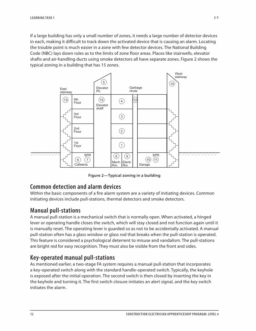
If a large building has only a small number of zones, it needs a large number of detector devices in each, making it difficult to track down the activated device that is causing an alarm. Locating the trouble point is much easier in a zone with few detector devices. The National Building Code (NBC) lays down rules as to the limits of zone floor areas. Places like stairwells, elevator shafts and air-handling ducts using smoke detectors all have separate zones. Figure 2 shows the typical zoning in a building that has 15 zones.
Figure 2—Typical zoning in a building
Common detection and alarm devicesWithin the basic components of a fire alarm system are a variety of initiating devices. Common initiating devices include pull-stations, thermal detectors and smoke detectors.
Manual pull-stationsA manual pull-station is a mechanical switch that is normally open. When activated, a hinged lever or operating handle closes the switch, which will stay closed and not function again until it is manually reset. The operating lever is guarded so as not to be accidentally activated. A manual pull-station often has a glass window or glass rod that breaks when the pull-station is operated. This feature is considered a psychological deterrent to misuse and vandalism. The pull-stations are bright red for easy recognition. They must also be visible from the front and sides.
Key-operated manual pull-stationsAs mentioned earlier, a two-stage FA system requires a manual pull-station that incorporates a key-operated switch along with the standard handle-operated switch. Typically, the keyhole is exposed after the initial operation. The second switch is then closed by inserting the key in the keyhole and turning it. The first switch closure initiates an alert signal, and the key switch initiates the alarm.

lEarning task 1 J-1
ConstruCtion ElECtriCian apprEntiCEship program: lEvEl 4 13
Manual pull-stations are installed on all floors, including basements, in corridors and lobbies, and at every exit to a stairwell or building. They are also installed in large meeting rooms, auditoriums, gymnasiums and so forth. All key-operated types must operate in the same manner and from the same keys. Some manual stations in buildings such as mental institutions will be key-operated only, due to the nature of the occupants. In these cases, the keys are held by the employees of the institution.
Figure 3 shows both the standard and key-operated manual pull-stations.
Figure 3—Manual pull-stations
Thermal detectorsThermal detector is another term for a heat detector. This type of detector responds to temperature change. Some respond to a temperature rise only, others to temperature rise as well as the rate at which the temperature rises.
Fixed-temperature heat detectorsA fixed-temperature detector may be a restorable or non-restorable type.
• In the restorable type, a bi-metal disc causes contact closure as it expands with the temperature rise. When the temperature decreases, the device is restored to its original state and the contacts reopen.
• In the non-restorable type, the heat causes a solder-based spot of metal to melt at a specified temperature. When it melts, it releases a plunger, causing contact closure. However, when the temperature decreases, there is no way the contact mechanism can be re-soldered, so the unit must be discarded and replaced.
lEarning task 1 J-1
14 ConstruCtion ElECtriCian apprEntiCEship program: lEvEl 4
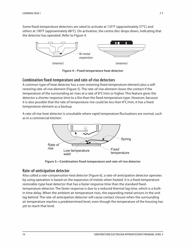
Some fixed-temperature detectors are rated to activate at 135°F (approximately 57°C) and others at 190°F (approximately 88°C). On activation, the centre disc drops down, indicating that the detector has operated. Refer to Figure 4.
(interior) (exterior)
Bi-metal expansion
Figure 4—Fixed temperature heat detector
Combination fixed-temperature and rate-of-rise detectorsA common type of heat detector has a non-restoring fixed-temperature element plus a self-restoring rate-of-rise element (Figure 5). The rate-of-rise element closes the contact if the temperature of the surrounding air rises at a rate of 8°C/min or higher. This feature gives the detector a shorter response time to a fire than the fixed-temperature type. However, because it is also possible that the rate of temperature rise could be less than 8°C/min, it has a fixed temperature element as a backup.
A rate-of-rise heat detector is unsuitable where rapid temperature fluctuations are normal, such as in a commercial kitchen.
-
Figure 5—Combination fixed-temperature and rate-of-rise detector
rate-of-anticipation detectorAlso called a rate-compensation heat detector (Figure 6), a rate-of-anticipation detector operates by using operation is based on the expansion of metals when heated. It is a fixed-temperature restorable-type heat detector that has a faster response time than the standard fixed-temperature detector. The faster response is due to a reduced thermal lag time, which is a built-in time delay. When the ambient air temperature rises, the expanding metal sensors in the unit lag behind. The rate-of-anticipation detector will cause contact closure when the surrounding air temperature reaches a predetermined level, even though the temperature of the housing has yet to reach that level.

lEarning task 1 J-1
ConstruCtion ElECtriCian apprEntiCEship program: lEvEl 4 15
Figure 6—Rate-compensation heat detector
Smoke detectorsSmoke detectors, in most cases, provide the earliest warning of a fire condition. Smoke generally precedes the heat that activates heat detectors and water sprinklers. The most commonly used smoke detectors are the ionization and photoelectric types.
Smoke detectors may be ceiling-mounted types or duct types. Duct types are mounted on the outside of air-handling ducts, with smoke sensor air sampling tubes projecting into the duct. Monitoring the presence of smoke or combustion products in air ducts is important because these air-handling systems feed oxygen into a fire situation. When the smoke detector is activated, blowers are shut down and dampers are closed.
Ionization detectorThe ionization detector is also known as a products-of-combustion smoke detector (Figure 7). This very sensitive smoke detector is triggered by the presence of “invisible smoke,” better named products-of-combustion. It contains a small quantity of radioactive material between positive and negative plates housed in an ionization chamber that is open to the atmosphere. Under normal conditions, a small ionization current (around 1 × 10-12 A) flows between the plates, but if particles of visible or invisible smoke enter the chamber, they reduce the ionization and the current flow is interrupted. The condition is monitored by solid-state circuitry, which then closes a contact to initiate a signal condition. The sensitivity of the detector is factory adjustable or, in some modern types, adjustable from the control panel to meet particular environmental conditions. If too sensitive, these devices may cause false alarms.
Ionization smoke detectors are more sensitive than the photoelectric types but are also more likely to set off false alarms. Ionization smoke detectors should not be used in areas of high humidity, excessive dust and vapours, or steam.

lEarning task 1 J-1
16 ConstruCtion ElECtriCian apprEntiCEship program: lEvEl 4
Figure 7—Ionization smoke detector
Photoelectric detectorThe photoelectric smoke detector, also known as an obstruction smoke detector, requires visible smoke to initiate a signal condition. When smoke enters the unit, it passes through a light beam, either blocking or scattering it. The light beam’s source and receiver are located in the housing, and the unit is open to the atmosphere, as shown in Figure 8. When the device operates, a set of contacts close to initiate the signals in the FA system.
Signal devices Signal devices are used to warn people of a fire situation. They may be audible, visible or a combination of both. Signal devices include vibrating and single-stroke bells, chimes, sirens, horns, speakers and flashing lights. The application depends on the type of occupancy of the building.

lEarning task 1 J-1
ConstruCtion ElECtriCian apprEntiCEship program: lEvEl 4 17
Figure 8—Photoelectric smoke detector
vibrating bell The vibrating bell is the oldest and most common alarm device. Standard available sizes are 4-inch, 6-inch and 10-inch diameters. The sound level increases with the size. The most common type is the 10-inch bell shown in Figure 9. Bells may be either 24 V DC or 120 V AC.
Single-stroke bellThe single-stroke bell is similar to the vibrating bell except that it produces single-stroke sounds only. In a two-stage system, the same bell is usually used to give both the single-stroke alert sound and the vibrating sound. This is controlled by relays in the control unit. Single-stroke bells and chimes are most often used for the alert stages of fire alarms.
ChimesThese low-intensity sound devices are used in quiet areas such as hospitals.
Horns and sirensHorns and sirens are most suitable in locations with high ambient noise levels, or where bells are commonly used for other purposes; for example, in a school where vibrating bells are used to signal class start. These devices are available with a wide range of sound intensities to overcome ambient sounds. They are also common in outer storage yards. See Figure 10.
Case moulding Infra red LED
Optical chamber
Cover
Photo diode
Figure 9—Vibrating bell

lEarning task 1 J-1
18 ConstruCtion ElECtriCian apprEntiCEship program: lEvEl 4
Figure 10—Sirens and horns
visual devicesVisual devices (Figure 11) are used in locations with high ambient noise or in buildings used by people with hearing impairments. These visual signals must not be regarded as replacements for audible devices; they must only be used along with audible devices.
Visual signals must be installed so that at least one light is visible—directly or indirectly—to every person in the building or premises. A visual device may be a spotlight or a sign that is readily distinguishable from normal lighting, but it is more likely to be a flashing strobe light or rotating reflecting light because these are usually easiest to spot.
Figure 11—Visual signal devices
lEarning task 1 J-1
ConstruCtion ElECtriCian apprEntiCEship program: lEvEl 4 19
LoudspeakersLoudspeakers operate as signal devices over the normal range of voice frequencies, and sound bell tones if the building needs to be evacuated. A handset in the control panel allows for signal override once the alarm bell tones have sounded. This is to allow the user to give emergency evacuation instructions over the loudspeakers. If loudspeakers are installed for more than this purpose, they must be installed so that the fire alarm signals take priority over all other signals. A typical FA loudspeaker is shown in Figure 12.
Control panelsAs mentioned earlier, the control panel houses the control unit, the “brains” of the FA system. It coordinates the initiating and signal devices, sends information to annunciator panels, often controls the operation of several ancillary devices, and in some installations, alerts municipal and fire halls. It gets its power supply from a separate circuit breaker (CB) in the electrical panel, which supplies electricity to no other equipment but the FA devices. It also has a backup power supply.
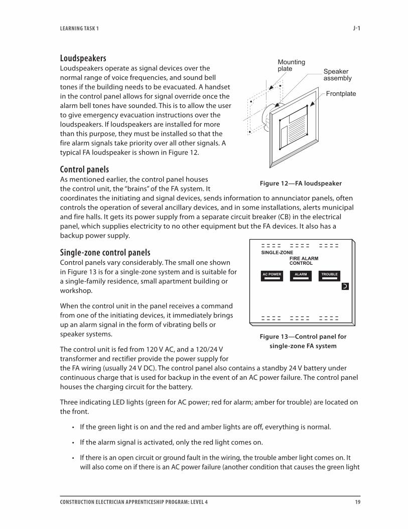
Single-zone control panelsControl panels vary considerably. The small one shown in Figure 13 is for a single-zone system and is suitable for a single-family residence, small apartment building or workshop.
When the control unit in the panel receives a command from one of the initiating devices, it immediately brings up an alarm signal in the form of vibrating bells or speaker systems.
The control unit is fed from 120 V AC, and a 120/24 V transformer and rectifier provide the power supply for the FA wiring (usually 24 V DC). The control panel also contains a standby 24 V battery under continuous charge that is used for backup in the event of an AC power failure. The control panel houses the charging circuit for the battery.
Three indicating LED lights (green for AC power; red for alarm; amber for trouble) are located on the front.
• If the green light is on and the red and amber lights are off, everything is normal.
• If the alarm signal is activated, only the red light comes on.
• If there is an open circuit or ground fault in the wiring, the trouble amber light comes on. It will also come on if there is an AC power failure (another condition that causes the green light
Figure 12—FA loudspeaker
Figure 13—Control panel for single-zone FA system

lEarning task 1 J-1
20 ConstruCtion ElECtriCian apprEntiCEship program: lEvEl 4
to go off ). A trouble light “on” condition will be accompanied by an audible trouble signal from a buzzer in the control panel. A remote trouble indicator unit may or may not be used.
Control panels contain:
• Terminal blocks for the wiring
• Electronic circuitry to coordinate the wiring and change the status of auxiliary contacts when abnormal conditions occur
• Push-buttons for testing the lamps
• Test points for checking the FA system
• Reset switches for silencing the trouble and alarm conditions
Multi-zone control panelA multi-zone control panel (Figure 14) is more complex than the single-zone type, since a multi-zone building ordinarily has a lot of equipment and features not required in a single-zone building. Along with the manual and automatic initiating devices (as in the simple FA system), it will likely include such things as:
• Sprinkler flow systems and switches
• Electromagnetic door release mechanisms
• Air-handling shutdown systems
• Selective initiate alarm and alert signals
• Evacuation telephone and public address voice systems
Figure 14—Typical multi-zone control panel for addressable system
lEarning task 1 J-1
ConstruCtion ElECtriCian apprEntiCEship program: lEvEl 4 21
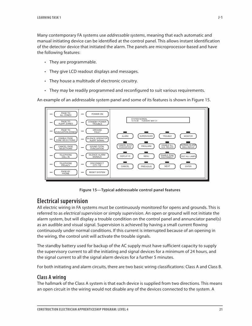
Many contemporary FA systems use addressable systems, meaning that each automatic and manual initiating device can be identified at the control panel. This allows instant identification of the detector device that initiated the alarm. The panels are microprocessor-based and have the following features:
• They are programmable.
• They give LCD readout displays and messages.
• They house a multitude of electronic circuitry.
• They may be readily programmed and reconfigured to suit various requirements.
An example of an addressable system panel and some of its features is shown in Figure 15.
DRILL/REPLAY
Figure 15—Typical addressable control panel features
Electrical supervisionAll electric wiring in FA systems must be continuously monitored for opens and grounds. This is referred to as electrical supervision or simply supervision. An open or ground will not initiate the alarm system, but will display a trouble condition on the control panel and annunciator panel(s) as an audible and visual signal. Supervision is achieved by having a small current flowing continuously under normal conditions. If this current is interrupted because of an opening in the wiring, the control unit will activate the trouble signals.
The standby battery used for backup of the AC supply must have sufficient capacity to supply the supervisory current to all the initiating and signal devices for a minimum of 24 hours, and the signal current to all the signal alarm devices for a further 5 minutes.
For both initiating and alarm circuits, there are two basic wiring classifications: Class A and Class B.
Class A wiringThe hallmark of the Class A system is that each device is supplied from two directions. This means an open circuit in the wiring would not disable any of the devices connected to the system. A

lEarning task 1 J-1
22 ConstruCtion ElECtriCian apprEntiCEship program: lEvEl 4
Class A wiring system is shown in Figure 16. The fact that all devices would still be operational in the event of an open circuit does not imply that electrical supervision is unnecessary.
All FA wiring today requires electrical supervision.
-
Fire AlarmControl PlanelTerminal Board
19 –
10 –
11 +
12 –
13 +
18 +
21 –
20 +
Figure 16—Class A wiring method
Class B wiringClass B wiring supplies the devices from one direction only. If an opening occurs in the wiring, all devices downstream will be out of commission. A feature of Class B wiring is the end-of-line device, which provides a current path for the supervisory current. Although diodes are occasionally used, the end-of-line resistor is more common. It is a colour-coded 0.5 W resistor, located in a separate box beyond the last initiating device or signal device in the respective circuits. Refer to Figure 17.
Under normal conditions a low (supervisory) current flows through the external wiring. If an initiating device operates, its NO contact closes and current increases. This is monitored in the panel and the polarity of the wires to the bells reverses, permitting current to pass through their coils, creating an alarm condition.

lEarning task 1 J-1
ConstruCtion ElECtriCian apprEntiCEship program: lEvEl 4 23
- -
- -
Figure 17—Class B wiring method
Most initiating and signal components are four-terminal devices. Pigtailing is not permitted, nor are tap-offs (except in some parts of addressable systems), because these impede electrical supervision. Refer to Figure 18.

lEarning task 1 J-1
24 ConstruCtion ElECtriCian apprEntiCEship program: lEvEl 4
Figure 18—Pigtailing and tap-offs
AnnunciatorsAnnunciators are panels located at one or more key points in a building. They provide visual indication of the signals received in a multi-zone FA system. Every FA system with more than one zone must have an electrically supervised annunciator at the main entrance of the building to allow firefighters to quickly see the area where the fire has occurred. This annunciator usually includes a floor plan or graphic illustration of the building with appropriate zone indicator alarm lights and their zone identifications. Figure 19 shows a typical annunciator panel display.
The number of annunciators required will depend on:
• Whether the FA system is single-stage or two-stage
• The number of main entrances to the building
• The system design

lEarning task 1 J-1
ConstruCtion ElECtriCian apprEntiCEship program: lEvEl 4 25
9
Figure 19—Annunciator panel display plate
In two-stage systems, there may be annunciator panels in locations such as administration offices, nursing stations and engineers’ offices. This provides for rapid and appropriate response to the fire call. There are different styles of annunciators, but each one must have a visual and audible trouble signal device.
Addressable fire alarm systemsIn an addressable system, a smoke, heat or manual initiating device (or a group of these devices) is given a number or address code. The CPU in the FA control panel monitors the individual devices (or groups of devices) and can identify which one initiated the signal. In general, it is only necessary to pinpoint the location where the device was activated, but it is also possible to have each initiating device on a separate address. These systems, though relatively new, are being used extensively in large apartment buildings and offices, hospitals, shopping malls and so on.
A group of smoke or heat detectors is usually connected to a transponder unit in a Class B wiring configuration. A transponder is a multiplexer—a device that permits a combination of different signals to be transmitted over a single line. Each transponder has a distinct address and monitors all output devices connected to it for any changes in status. It then relays the information back to the main control panel. The microprocessor in the main panel is pre-programmed, to instruct a transponder to activate or not activate any of the devices connected to it, based on the information it receives (Figure 20).

lEarning task 1 J-1
26 ConstruCtion ElECtriCian apprEntiCEship program: lEvEl 4
Figure 20—Communication between main control panel and transponder
All transponders are regularly polled by the communication loops between them and the computer in the main panel. Individual addressable sensors are also polled. These analogue addressable transponders and sensors relay analogue information back to the computer and allow for adjustment of sensitivity and verifiability from the main control panel. Up to five sensitivity settings are possible with smoke detectors.
The transponder is connected to the control panel by a twisted pair of shielded wires. These two wires transmit the signals to the control unit CPU. Other transponders and/or addressable devices may tapoff this run. This system is cost-effective in larger FA systems because of the savings in the many runs of wire that otherwise have to be run in. In addressable systems, the rules on tapoffs that apply to conventional systems do not necessarily apply. The wiring for an addressable system is shown in Figure 21.
A system designed to protect lives and property must not be easily accessible. Therefore, programming is done at the factory. However, a certain amount of access may be made available to persons authorized to work with the system.
This limited access makes troubleshooting these systems difficult. If a transponder is not relaying information, for example, it most likely needs replacing. However, the output devices that connect to the unit can be disconnected at the unit and checked in the conventional manner.

lEarning task 1 J-1
ConstruCtion ElECtriCian apprEntiCEship program: lEvEl 4 27
Figure 21—Addressable FA wiring system
Courtesy of Edwards
Smoke and heat detectors and manual pull-stations are addressable devices. Traditional, non-addressable devices include vibrating bells, strobe lights, speakers and so forth. An addressable device requires an address, a dipswitch and microchip circuitry. (An addressable smoke detector may use a standard head with an addressable base.) Non-addressable devices connect to addressable transponders. If a device is activated, the transponder to which it is connected reveals the area in which the device is located. This is normally sufficient information. Addressable devices, however, pinpoint the exact location, but these cost more and involve additional wiring expenses.
Installation and wiring requirementsSeveral agencies have input into the design, installation, verification and testing of FA installations. These agencies include:
• National Building Code (NBC)
• Underwriters Laboratories of Canada (ULC)
• Canadian Standards Association (CSA)

lEarning task 1 J-1
28 ConstruCtion ElECtriCian apprEntiCEship program: lEvEl 4
• Canadian Electrical Code (CEC)
• National Fire Code (NFC)
• Provincial and municipal fire authorities
People working in FA systems should be familiar with these agencies and their publications.
Manual pull-stationsManual stations shall be installed not less than 1200 mm and not more than 1400 mm above the finished floor level measured to the centre of the manual station. Manual pull-stations must be installed at every stairway exit and entrance, and it must be impossible to exit a floor area without passing a pull-station.
Audible signal devicesThese devices must be mounted so that the centre of the device will be not less than 1.8 m above the floor level. If the signal device is a loudspeaker with voice reproduction capability, the CAN/ULC Standards requires that it be mounted in accordance with the manufacturer’s recommendations. It must be audible to all occupants within the area served by the signal device.
visual signal appliancesWhen visual signal appliances are required, they must always be installed so that at least one can be seen by every person in the room or area.
Control panelThe top of the control panel must not be more than 2.4 m above the finished floor.
AnnunciatorsAn annunciator panel must be wall-mounted, and the top of the panel must not be more than 2.4 m above the finished floor. The CAN/ULC Standards state that where annunciators are required, at least one must be located and readily visible at the main entrance of the building at street level.
End-of-line devicesThe end-of-line device is usually located in a separate box beyond the last signal or initiating device, but it can also be located in the control panel. When located in a separate box, the CAN/ULC Standards state that these devices must be beyond the last initiating or signal device, and that the box must be not more than 1.8 m above the finished floor. End-of-line devices are usually colour-coded, 0.5 W resistors used in conventional Class B circuits.
Smoke and heat detectorsThese devices are normally ceiling-mounted, so designated heights are not stated. But the ULC does state rules about their placement, separation, area coverage and so forth. Note that this is beyond the scope of the material covered in this Learning Task.
lEarning task 1 J-1
ConstruCtion ElECtriCian apprEntiCEship program: lEvEl 4 29
CEC rulesThe Canadian Electrical Code (CEC) is responsible for the rules governing wiring methods. Section 32 of the CEC covers the rules pertaining to FA systems and fire pumps. The rules in Section 32 are in addition, or amendatory, to the general sections 0–16 and 26. It is the Building Code that stipulates when an FA system is required, and what type. The CEC in Section 32 then stipulates the minimum conductor sizes, acceptable cables, methods of connection and so on. The following rules are relevant to FA installations.
Conductors (rule 32-100)Conductors must be copper and must have sufficient ampacity to carry the maximum current of the circuit. Signal wires are commonly #14 or #16 AWG. Wires in the initiating circuits are usually smaller. Conductors must have an insulation rating of not less than 300 V.
The absolute minimum conductor size is #22 AWG. This can be used only when it is part of a cable having a minimum of four conductors. Stranded conductors with more than seven strands must be bunch-tinned, or else terminated in compression connectors.
Wiring methods (rule 32-102)It is important that conductors used in the FA system be physically protected. The CEC states that such conductors must be in one of the following:
• Totally enclosed metal raceways.
• Cables having a metal armour or sheath.
• Rigid non-metallic conduits when embedded in concrete or masonry (minimum depth of 50 mm); but if the building is of wood-frame construction (as opposed to a high-rise building), the CEC accepts standard NMSC (non-metallic sheathed cable) or FA and signal cable.
These conductors must be for the FA system only and must not enter fixtures, boxes, raceways or other enclosures by other wiring unless that wiring is associated with the point of supply, signal, ancillary device or communication circuit. For the wiring of a communication system that extends beyond the building in question, Section 60 of the CEC applies.
Electrical supervision (rule 32-106)Rule 32-106 requires wires to detectors, pull-stations and signal devices to be terminated in such a manner that the removal of a component will interrupt the supervisory current and bring up a trouble signal. These devices will be either four-terminal devices or have dual splice leads.
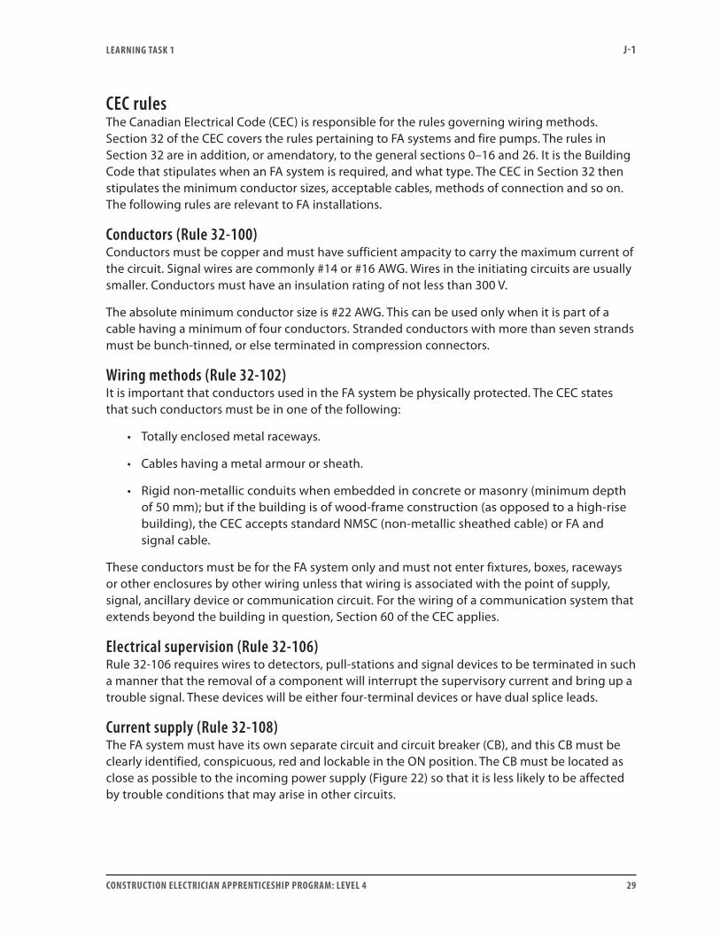
Current supply (rule 32-108)The FA system must have its own separate circuit and circuit breaker (CB), and this CB must be clearly identified, conspicuous, red and lockable in the ON position. The CB must be located as close as possible to the incoming power supply (Figure 22) so that it is less likely to be affected by trouble conditions that may arise in other circuits.

lEarning task 1 J-1
30 ConstruCtion ElECtriCian apprEntiCEship program: lEvEl 4
Figure 22—Typical FA power supply arrangement
Testing and inspection of FA system wiringBefore the FA system is connected to the wiring terminals on the control panel, it should be tested for short circuits between wires, opens and grounds. Use a good-quality ohmmeter when testing FA wiring.
Caution! Do not use a megger, because many meggers generate a voltage of 500 V and will likely damage electronic components in the FA system.
If the external wiring proves free of any problems, and there is a fault condition after connection, the problem is likely in the panel or in one of the devices.
Opens and shorts (initiating circuits)Check for opens and shorts by connecting an ohmmeter as shown in Figure 23.
Figure 23—Checking an initiating circuit, Class B wiring

lEarning task 1 J-1
ConstruCtion ElECtriCian apprEntiCEship program: lEvEl 4 31
For manual pull-stations, heat detectors and non-ionization smoke detectors, the ohmmeter should read the magnitude of the end-of-line resistor when checking the initiating circuit, regardless of the polarity of the meter leads.
If a short is indicated, it could be due to such things as an incorrect wiring connection, a closed automatic detector or a manual pull-station that has been activated. Any of these conditions can cause an alarm after connection if they are not corrected.
If an open circuit is indicated, it could be due to a wire not connected to a terminal, a break in the wire, a shorting strip supplied with a detector base not in place, or a missing or unconnected end-of-line device. An open circuit will cause a trouble signal when connected to an energized control panel.
If ionization smoke detectors are being used, leave the shorting device supplied with the detector base installed until after the wires have been checked. Otherwise, an incorrect reading will result. The detector is plugged into the base after the wiring tests are completed. Since the circuits between the base terminals are usually completed within the detector, it is necessary to jumper some terminals to permit testing.
Opens and shorts (signal circuits)Figure 24 shows a signal circuit checked for opens and shorts.
Figure 24—Checking a signal circuit, Class B wiring
When checking the bells, the ohmmeter reading should be that of the end-of-line resistor, provided the diodes in the bell circuits are reverse-biased to the ohmmeter. Bells normally have diodes that are series-connected with their operating coils. If the leads of the ohmmeter are reversed, the reading will be 500 Ω or less, depending on the number of bells on that circuit. If the reading is around this magnitude for both, it is likely that some bells have been connected with reverse polarity. If a polarized bell is connected backwards, it will energize once it is connected to the control panel and the panel is energized. A short-circuit condition will blow fuses and an open-circuit condition will cause a trouble signal.
If a short is indicated, it may be due to an incorrect wiring connection. If an open circuit is indicated, it could be due to a wire not connected to a terminal, a break in the wire, or a missing or unconnected end-of-line device.
A common practice when tracking down trouble in wiring is to start working from the centre point of the initiating or signal circuit toward the end-of-line device, and then from the centre
lEarning task 1 J-1
32 ConstruCtion ElECtriCian apprEntiCEship program: lEvEl 4
point back to the control panel. An end-of-line resistor is placed across the outgoing pair at the panel terminals. The wires are disconnected at the centre device and metered in both directions. The problem can then be isolated to eliminate half the wiring. It can then be further pinpointed by continuing this process.
ground faultsA single ground on the wiring will not prevent the operation of the system. But a second ground could result in an alarm condition or a blown fuse, depending on where the grounds have occurred.
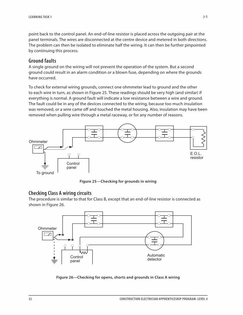
To check for external wiring grounds, connect one ohmmeter lead to ground and the other to each wire in turn, as shown in Figure 25. These readings should be very high (and similar) if everything is normal. A ground fault will indicate a low resistance between a wire and ground. The fault could be in any of the devices connected to the wiring, because too much insulation was removed, or a wire came off and touched the metal housing. Also, insulation may have been removed when pulling wire through a metal raceway, or for any number of reasons.
Figure 25—Checking for grounds in wiring
Checking Class A wiring circuitsThe procedure is similar to that for Class B, except that an end-of-line resistor is connected as shown in Figure 26.
Figure 26—Checking for opens, shorts and grounds in Class A wiring
lEarning task 1 J-1
ConstruCtion ElECtriCian apprEntiCEship program: lEvEl 4 33
Faults after connectionIf a fault arises after the external wiring has been connected to the panel, disconnect the external wires from the terminals and place an end-of-line resistor across the two terminals. If the trouble signal remains, the problem is in the panel. If it disappears, it is in the external wiring. Ground faults can be caused by water leaking into a raceway or any other equipment that houses the FA wiring. Open circuits can be caused by careless connections to devices, or by “ringing” the conductor when stripping the insulation. In the latter case, the conductor has been partly severed, then breaks later due to vibration or handling.
Checking trouble signal operationControl panels and annunciator panels should identify FA problems such as open circuits, grounds, low battery conditions and loss of power supply as trouble signals. These appear as a flashing amber light along with a buzzer sound. To check that the system works, ground one wire in the initiating or signal circuit and verify that the system is functioning. This ground can be applied at the control panel or at one of the devices under normal system operation. Remember that a single ground does not bring up an alarm signal, but it should bring up a visual and audible trouble signal on the control panel, indicating in which zone the trouble is located.
False alarmsFalse fire alarm signals may be caused by vandals pulling manual pull-stations or activating heat or smoke detectors. They may also be caused by detectors that are faulty, too sensitive for their location or poorly placed. Smoke detectors near exhaust fumes, or rate-of-rise heat detectors near heating vents, are prime candidates for false alarms.
Testing the FA installationTesting means checking the devices to ensure that they function properly. This is done after all system wiring problems have been checked. (Standards for verification of the FA system are published by the ULC.) The testing must be done by qualified persons who are acceptable to the authority having jurisdiction. Testing of devices includes some of the following:
• All manual pull-stations must be individually operated to test if they are capable of initiating an alarm condition.
• Automatic FA initiating devices, including heat, smoke and water flow devices, must be tested in accordance with the FA manufacturers’ instructions.
• The control panel and annunciators must be checked as each initiating device is operated to ensure the proper zone is annunciated.
• Heat detectors of the restorable type can be readily tested using an acceptable FA manufacturers’ heat source. Do not use an open flame.
• A percentage of the non-restorable types must be tested.
• Smoke detectors and signal devices must be tested for operation.
It is your job as an electrician to install the wiring system, to correctly connect the various components and to ensure that everything is free of faults. The installer will also be involved with the testing in conjunction with the equipment supplier and local fire inspector.

lEarning task 1 J-1
34 ConstruCtion ElECtriCian apprEntiCEship program: lEvEl 4
All tests must be recorded and documented. Everything must be functioning properly before the authority having jurisdiction will accept the system.
FA system maintenanceBuilding owners or their agents must have a fire safety plan for each building. A record of checks must be kept in a log book, recording inspections, testing and repairs of all FA components. These records must be retained for inspection by the authority having jurisdiction. It is essential that FA systems be maintained in operating condition at all times. When a trouble signal comes up on the control or annunciator panel, it must be responded to and fixed without delay. If something is neglected and a fire occurs, there may be serious problems later with claims.
The National Fire Code requires regular checking, testing and inspection of FA systems and voice communication systems.
Now do Self-Test 1 and check your answers.

lEarning task 1 J-1
ConstruCtion ElECtriCian apprEntiCEship program: lEvEl 4 35
self-test 1
1. The primary function of a FA system is to protect .
2. Name three basic elements of any FA system.
3. Most FA automatic initiating devices respond to and
.
4. The most common FA signal devices are and .
5. The heart of a FA system is the .
6. In the single-stage FA system, what happens when an initiating device operates?
7. In a two-stage FA system, what usually happens when a manual pull-station is operated?
8. A typical zone in a building might be a or .
9. Name one advantage of having many zones in a building.
10. What special feature must all manual pull-stations in a two-stage FA system incorporate?
11. Name the three most common initiating devices.

lEarning task 1 J-1
36 ConstruCtion ElECtriCian apprEntiCEship program: lEvEl 4
12. Where would it not be practical to use a rate-of-rise heat detector?
13. Are all thermal detectors restorable types?
14. Which type of automatic fire detector usually gives the earliest warning of a fire condition?
15. What is the reason for using smoke detectors in air-handling duct systems?
16. What are the two most common types of smoke detectors?
17. Which type of smoke detector would be most suitable in an area of high ambient humidity?
18. What is the function of a key-operated manual pull-station?
19. Is a rate-of-anticipation detector restorable? What advantage does it have over a standard fixed-temperature thermal detector?
20. Identify three locations where manual pull-stations are normally required.

lEarning task 1 J-1
ConstruCtion ElECtriCian apprEntiCEship program: lEvEl 4 37
21. Are single-stroke bells (and chimes) usually used for alert signals or alarm signals?
22. The common voltage used in FA wiring is .
23. In a typical control panel, what do the green, amber and red lights signify?
24. What is the reason for “supervising” FA systems?
25. How is electrical supervision of wiring accomplished in an FA system?
26. The standby battery used in FA systems must have enough capacity to supply the
supervisory current for a minimum of how long?
27. Which class of FA wiring uses the end-of-line resistor?
28. Name one advantage and one disadvantage of the Class A system.
29. Which two features of the addressable FA system make it advantageous over the non-addressable system for certain installations?
lEarning task 1 J-1
38 ConstruCtion ElECtriCian apprEntiCEship program: lEvEl 4
30. If an opening occurs in a Class B wiring system because a wire comes off the terminal of the end-of-line resistor, all devices on that zone are de-activated.
a. True
b. False
31. Where must an annunciator be located in a building?
32. What type of FA systems require annunciator panels?
33. What features would you expect to find in a typical FA annunciator panel?
34. What are the mounting height requirements for manual pull-stations?
35. What are the mounting height requirements for alarm bells?
36. What are the mounting height requirements for the control panel?
37. What are the mounting height requirements for end-of-line resistors?
38. Where are smoke and heat detectors normally mounted?
39. Conductors used in FA systems must be of what material?
40. What is the minimum size of conductor permitted in FA wiring?

lEarning task 1 J-1
ConstruCtion ElECtriCian apprEntiCEship program: lEvEl 4 39
41. What does the CEC rule say about stranded wires in FA systems?
42. Is it permitted to put non-FA equipment on the FA circuit?
43. How must the circuit breaker for the FA circuit be identified?
44. What are the Code requirements for the FA circuit-breaker location?
45. Why is it not advisable to use a megger to test FA systems?
46. An ohmmeter is used to test FA wiring for what types of faults?
47. If an initiating circuit is a Class B type having four heat detectors and a manual pull-station, what reading should you expect on an ohmmeter connected to the two wires that will connect to the control panel?
48. When an ohmmeter is connected across the polarized bell circuit wires as shown in Figure 1,
what reading would you get?
Figure 1
49. If the leads of the meter in Figure 1 were reversed, should the reading increase or decrease
compared to the previous reading?

lEarning task 1 J-1
40 ConstruCtion ElECtriCian apprEntiCEship program: lEvEl 4
50. For the circuit test in Figure 2, if the system is working properly, should the ohms reading on
the meter be high, low or somewhere in between?
Figure 2
51. What would be the reason for connecting an end-of-line resistor to the output wiring terminals in place of the signal or initiating wires when making an ohmmeter test?
52. Some, but not all, manual pull-stations are required to be tested in an FA system.
a. True
b. False
53. When testing the FA system, only the restorable heat detectors are tested and no testing is done on non-restorable types.
a. True
b. False
54. What agency publishes the standards for testing FA systems?
55. List the five regulatory groups that have input regarding FA systems.
Go to the Answer Key at the end of the Learning Guide to check your answers.

answEr kEy J-1
ConstruCtion ElECtriCian apprEntiCEship program: lEvEl 4 41
answer key
Self-Test 11. people
2. • Initiatingdevices• Signal devices• Control unit
3. smoke, heat
4. bells, speakers
5. control panel
6. All signal devices go into alarm.
7. Signal devices initially go to an alert condition. This may be followed by an alarm condition.
8. floor, wing
9. Makes it easier to track down the location of the trouble spot.
10. key-operated switch
11. manual pull-stations, heat detectors, smoke detectors
12. in a commercial kitchen
13. no
14. ionization smoke detector
15. to shut down fans and dampers that might worsen the fire situation
16. Ionization type and photoelectric type
17. Photoelectric type
18. To enable the operator to change an alert signal to an alarm signal
19. Yes. It responds faster to ambient air temperature rise.

answEr kEy J-1
42 ConstruCtion ElECtriCian apprEntiCEship program: lEvEl 4
20. • Entrancestostairways• Exits• Large assembly rooms
21. alert signals
22. 24 V DC
23. • GreenisforACpowersupply.• Amber is for trouble condition.• Red is for alarm condition.
24. to monitor the wiring to ensure no open or ground conditions are present that would inhibit the operation of the devices should a fire situation arise
25. By maintaining a continuous current in the wiring. Any interruption brings up a trouble signal.
26. 24 hours
27. Class B
28. An open in the wiring system does not knock out any of the initiating or signal devices, but installation costs are higher because of this additional wiring.
29. Activated devices are easily identifiable, and the wiring costs are often less.
30. b. False
31. at the main door entrance to the building at street level
32. FA installations that have more than one zone
33. a map of the building and zone alarm indicating lights, plus a trouble light and an audible signal device
34. 1.35 m to 1.5 m to centre above floor
35. not less than 1.8 m to centre above floor
36. not more than 2.4 m to top above floor
37. not more than 1.8 m above floor
38. on the ceiling

answEr kEy J-1
ConstruCtion ElECtriCian apprEntiCEship program: lEvEl 4 43
39. copper
40. #22 AWG
41. Stranded conductors with more than seven strands must be bunch-tinned, or terminated in compression connectors.
42. no
43. Clearly and conspicuously, and it must be red
44. It must be located as close as possible to the incoming power supply.
45. Electronic components could be damaged by excessive megger voltage.
46. opens, shorts and grounds
47. end-of-line resistor value (approximately)
48. 22 kΩ
49. decrease
50. high
51. to check if the problem is in the control panel
52. b. False
53. b. False
54. the ULC
55. NBC, CEC, ULC, NFC, CSA


7960003587
ISBN 978-0-7726-6791-5
9 780772 667915