learning robotics using python - sample chapter
TRANSCRIPT

Free Sample

In this package, you will find: • The author biography • A preview chapter from the book, Chapter 2 'Mechanical Design
of a Service Robot' • A synopsis of the book’s content • More information on Learning Robotics Using Python
About the Author Lentin Joseph is an electronics engineer, robotics enthusiast, machine vision expert, embedded programmer, and the founder and CEO of Qbotics Labs (http://www.qboticslabs.com) in India. He got his bachelor's degree in electronics and communication engineering at the Federal Institute of Science and Technology (FISAT), Kerala. In his final year engineering project, he created a social robot, which can interact with people. The project was a huge success and got mentioned in visual and print media. The main feature of this robot was that it could communicate with people and reply intelligently. It also has some image-processing capabilities, such as face, motion, and color detection. The entire project was implemented using the Python programming language. His interest in robotics, image processing, and Python began this project.
After graduation, he worked at a start-up company based on robotics and image processing for 3 years. In the meantime, he learned famous robotic software platforms—such as Robot Operating system (ROS), V-REP, and Actin (a robotic simulation tool)—and image processing libraries, such as OpenCV, OpenNI, and PCL. He also knows about robot 3D designing, embedded programming on Arduino, and Stellaris Launchpad.
After 3 years of work experience, he started a new company called Qbotics Labs, which is mainly focused on research to build great products in domains such as wearable technology, robotics, machine vision, green technology, and online education. He maintains a personal website (http://www.lentinjoseph.com) and a technology blog called technolabsz (http://www.technolabsz.com). He publishes his works on his tech blog. He was a speaker at PyCon2013 India, and he spoke on the topic of learning robotics using Python.

Learning Robotics Using Python Learning Robotics with Python contains twelve chapters that mainly aims at how to build an autonomous mobile robot from scratch and how to program it using Python. The robot mentioned in this book is a service robot, which can be used to serve food at home, hotels, and restaurants. From the beginning to end, this book discusses the step-by-step procedure on how to build this robot. The book starts with the basic concepts of robotics and then moves on to the 3D modeling and simulation of the robot. After the successful simulation of the robot, it discusses the hardware components required to build the robot prototype in order to complete the robot navigation.
The software part of this robot is mainly implemented using the Python programming language and software frameworks, such as Robot Operating System (ROS), Open-CV, and so on. You will understand the application of Python from the aspects of designing the robot to the robot’s user interface. The Gazebo simulator is used to simulate the robot and machine vision libraries, such as Open-CV and OpenNI. PCL is used to process the 2D and 3D image data of the robot. Each chapter is presented with an adequate theory to understand the application aspect. The book is reviewed by experts in this field who are passionate about robotics.
What This Book Covers Chapter 1, Introduction to Robotics, contains basic concepts and terminologies of robotics. This chapter is a must for beginners who are just starting with robotics.
Chapter 2, Mechanical Design of a Service Robot, discusses the 2D and 3D CAD designing aspect of the robot using LibreCAD and Blender (free software). This chapter also demonstrates how to use Blender Python APIs in order to build the 3D model.
Chapter 3, Working with Robot Simulation Using ROS and Gazebo, takes you through the simulation of the service robot using Gazebo and ROS.
Chapter 4, Designing ChefBot Hardware, explains the hardware designing of the robot, including block diagram and hardware components required to build ChefBot.
Chapter 5, Working with Robotic Actuators and Wheel Encoders, covers interfacing of robotic actuators and wheel encoders using Tiva C LaunchPad. It also mentions high-end smart actuators like dynamixel.
Chapter 6, Working with Robotic Sensors, discusses interfacing of ultrasonic distance sensors, IR proximity sensors, and IMU using Tiva C LaunchPad.

Chapter 7, Programming Vision Sensors Using Python and ROS, talks about the introduction to Open-CV, OpenNI, and PCL libraries and interfacing these to ROS and programming using Python.
Chapter 8, Working with Speech Recognition and Synthesis Using Python and ROS, discusses speech recognition and synthesis using various libraries and interfacing it to ROS programming using Python.
Chapter 9, Applying Artificial Intelligence to ChefBot Using Python, covers tutorials to build a ChatterBot. This can be used to make the robot interactive.
Chapter 10, Integration of ChefBot Hardware and Interfacing it into ROS, Using Python, explores tutorials to integrate the complete hardware and essential software section. It mainly discusses autonomous navigation of the service robot and how to program it using ROS and Python.
Chapter 11, Designing a GUI for a Robot Using Qt and Python, covers tutorials on how to build a GUI for the user who operates the robot in a typical restaurant. The GUI is built using Qt and the PyQt Python wrapper.
Chapter 12, The Calibration and Testing of ChefBot, explores tutorials on how to calibrate and test the robot for the final run.

[ 17 ]
Mechanical Design of a Service Robot
The main purpose of this book is to learn robotics by designing and building robots and programming it using Python. To learn robotics, we will fi rst look at how to mechanically design a robot from scratch. The robot that we are going to build is used as a service robot in hotels and restaurants to serve food and drinks.
In this chapter, we can see various mechanical components used in this robot. Also, we can see how to assemble its components. We can design and assemble the parts using CAD tool and also build a 3D model of robot for simulating the robot.
The actual robot deployed in hotels may be big, but here we are intending to build a miniature version of it only for testing our technology. If you are interested to build a robot from scratch, this chapter is for you. If you are not interested to build the robot, you can choose some robotic platforms already available on the market to work with this book.
To build the robot body, we fi rst need to know the requirements of designing the robot; after getting the requirements, we can design it and draw the model in 2D CAD tools to manufacture the robot parts. We can also discuss the 3D model to simulate the robot for the next chapter.

Mechanical Design of a Service Robot
[ 18 ]
The Requirements of a service robotBefore designing any robotic system, the fi rst procedure is to identify its requirements. The following are a set of hardware requirements to be met by this robot:
• The robot should have a provision to carry food• The robot should be able to carry a maximum payload of 5 kg• The robot should travel at a speed between 0.25 m/s and 1 m/s• The ground clearance of the robot should be greater than 3 cm• The robot must be able to work for 2 hours continuously• The robot should be able to move and supply food to any table
avoiding obstacles• The robot height should be between 40 cm and 1 meter• The robot should be of low cost
Now, we can identify the mechanical design requirements such as payload, moving speed, ground clearance, robot height, and the cost of the robot. We will design the body and select components accordingly. Let's discuss the robot mechanism we can use to match these requirements.
Robot drive mechanismOne of the cost effective solution for mobile robot navigation is differential drive systems. It's one of the simplest drive mechanisms for a mobile robot that is mainly indented for indoor navigation. The differential drive robot consists of two wheels mounted on a common axis controlled by two separate motors. There are two supporting wheels called caster wheels. It ensures stability and weight distribution of the robot. The following diagram shows a typical differential drive system:

Chapter 2
[ 19 ]
Differential drive system
The next step is to select the mechanical components of this robot drive system, that is, mainly motors, wheels, and robot chassis. Based on the requirements, we will fi rst discuss how to select the motor.
Selection of motors and wheelsMotors are selected after looking at their specifi cations. Some of the important parameters for motor selection are torque and RPM. We can compute these values from the given requirements.
Calculation of RPM of motorsAssume the required robot's speed as 0.35 m/s. We saw the speed of robot must be within 0.25 m/s to 1 m/s, as per the requirement. Take the diameter of the wheel as 9 cm because according to the requirement, the ground clearance should be greater than 3 cm. Using the following equation, we can calculate the RPM of motors:
RPM = ((60 * Speed /(3.14 * Diameter of Wheel)
RPM = (60 * 0.35 )/(3.14 * 0.09) = 21 / 0.2826 = 74 RPM

Mechanical Design of a Service Robot
[ 20 ]
You can also take a look at http://www.robotshop.com/blog/en/vehicle-speed-rpm-and-wheel-diameter-finder-9786 for computation.
The calculated RPM with 9 cm diameter wheel and 0.35 m/s speed is 74 RPM. We can consider 80 RPM as the standard value.
Calculation of motor torqueLet's calculate the torque required to move the robot:
1. No of wheels = Four wheels including two caster wheels.2. No of motors = Two.3. Let's assume the coeffi cient of friction is 0.6 and radius of wheel is 4.5 cm.4. Take total weight of robot = weight of robot + payload = (W = mg) = (~ 100 N
+ ~ 50 N) W= ~ 150 N, whereas total mass = 15 Kg5. The weight acting on the four wheels can be written as 2 * N1 + 2 * N2 = W,
that is, N1 is the weight acting on each caster wheel and N2 on each motor wheel.
6. Assume that the robot is stationary. The maximum torque is required when the robot starts moving. It should also overcome friction.
7. We can write the frictional force as robot torque = 0 until the robot moves. If we get the robot torque in this condition, we get the maximum torque as follows:μ * N * r - T = 0, where μ is the coeffi cient of friction, N is the average weight acting on each wheel, r is the radius of wheels, and T is the torque.N = W/4 ( assuming that the weight of the robot is equally distributed on all the four wheels)Therefore, we get:0.6 * (150/4) * 0.045 - T = 0Hence, T = 1.0125 N-m or 10.32 Kg-cm
The design summaryAfter design, we calculated the following values:
• Motor RPM = 80• Motor Torque = 10.32 kg-cm• Wheel diameter = 9 cm

Chapter 2
[ 21 ]
Robot chassis designAfter computing the robot's motor and wheel parameters, we can design the robot chassis or robot body. As required, the robot chassis should have a provision to hold food, it should be able to withstand up to 5 kg payload, the ground clearance of the robot should be greater than 3 cm and it should be low in cost. Apart from this, the robot should have a provision to place electronics components such as Personal Computer (PC), sensors, and battery.
One of the easiest designs to satisfy these requirements is a table-like design. The TurtleBot (http://www.turtlebot.com/) design is a kind of table-like design. It has three layers in the chassis. A robot platform called Roomba is the drive mechanism of this platform. The Roomba platform has motors and sensors inbuilt, so no need to worry about the designing of robot hardware. The following fi gure shows the TurtleBot robot chassis design:
TurtleBot Robot
We will design a robot similar to TurtleBot with our own moving platform and components. Our design will also have a three layer architecture. Let's see what all tools we want before we start designing.
Before we start designing the robot chassis, we need to know about Computer-aided design (CAD) tools. The popular tools available for CAD are:
• SolidWorks (http://www.solidworks.com/default.htm)• AutoCAD (http://www.autodesk.com/products/autocad/overview)• Maya (http://www.autodesk.com/products/maya/overview)• Inventor (http://www.autodesk.com/products/inventor/overview)• Google SketchUp (http://www.sketchup.com/)• Blender (http://www.blender.org/download/)• LibreCAD (http://librecad.org/cms/home.html)

Mechanical Design of a Service Robot
[ 22 ]
The chassis design can be designed using any software you are comfortable with. Here, we will demonstrate the 2D model in LibreCAD and the 3D model in Blender. One of the highlights of these applications is that they are free and available for all OS platforms. We will use a 3D mesh viewing tool called MeshLab to view and check the 3D model design and use Ubuntu as the main operating system. Also, we can see the installation procedures of these applications in Ubuntu 14.04.2 to start the designing process. We will provide tutorial links to install applications in other platforms too.
Installing LibreCAD, Blender, and MeshLabLibreCAD is a free, open source 2D CAD application for Windows, OS X, and Linux. Blender is a free, open source 3D computer graphics software used to create 3D models, animation, and video games. It comes with a GPL license as per which users can share, modify, and distribute the application. MeshLab is an open source, portable, and extensible system to process and edit unstructured 3D triangular meshes.
The following are the links to install LibreCAD in Windows, Linux, and OS X:
• Visit http://librecad.org/cms/home.html to download LibreCAD• Visit http://librecad.org/cms/home/from-source/linux.html to
build LibreCAD from source• Visit http://librecad.org/cms/home/installation/linux.html to
install LibreCAD in Debian/Ubuntu• Visit http://librecad.org/cms/home/installation/rpm-packages.
html to install LibreCAD in Fedora• Visit http://librecad.org/cms/home/installation/osx.html to
install LibreCAD in OS X

Chapter 2
[ 23 ]
• Visit http://librecad.org/cms/home/installation/windows.html to install LibreCAD in Windows
We can fi nd the documentation on LibreCAD at the following link:http://wiki.librecad.org/index.php/Main_Page.
Installing LibreCADThe installation procedure for all operating systems is provided. If you are an Ubuntu user, you can simply install it from the Ubuntu Software Centre as well.
Installing BlenderVisit the following download page to install Blender for your OS platform: http://www.blender.org/download/. You can fi nd the latest version of Blender here. Also, you can fi nd the latest documentation on Blender at http://wiki.blender.org/.
If you are using Ubuntu/Linux, you can simply install Blender via Ubuntu Software Centre.
Installing MeshLabMeshLab is available for all OS platforms. The following link will provide you the download links of prebuilt binaries and source code of MeshLab:
http://meshlab.sourceforge.net/
If you are an Ubuntu user, you can install MeshLab from an apt package manager using the following command:
$sudo apt-get install meshlab

Mechanical Design of a Service Robot
[ 24 ]
Creating a 2D CAD drawing of the robot using LibreCADWe can take a look at the basic interface of LibreCAD. The following screenshot shows the interface of LibreCAD:

Chapter 2
[ 25 ]
A CAD toolbar has the necessary components to draw a model. The following screenshot shows the detailed overview of the CAD toolbar:
A detailed description of LibreCAD tools is available at the following link:
http://wiki.librecad.org/index.php/LibreCAD_users_Manual.
• Command Box: This is used to draw fi gures by only using commands. We can draw diagrams without touching any toolbar. A detailed explanation about the usage of the command box can be found at:http://wiki.librecad.org/index.php/A_short_manual_for_use_from_the_command_line.
• Layer List: This will have layers used in the current drawing. A basic concept in computer-aided drafting is the use of layers to organize a drawing. A detailed explanation of layers can be found at:http://wiki.librecad.org/index.php/Layers.

Mechanical Design of a Service Robot
[ 26 ]
• Block: This is a group of entities and can be inserted in the same drawing more than once with different attributes at different locations, different scale, and rotation angle. A detailed explanation of Blocks can be found at the following link:http://wiki.librecad.org/index.php/Blocks.
• Absolute Zero: This is the origin of the drawing (0,0).
Now, start sketching by setting the unit of drawing. Set the drawing unit to centimeter. Open LibreCAD, navigate to Edit | Application Preference. Set Unit as Centimeters, as shown in the following screenshot:
Let's start with the base plate design. The base plate has provisions to connect motors, place battery, and control board.

Chapter 2
[ 27 ]
The base plate designThe following fi gure shows the robot's base plate. This plate provides provisions for two motors for differential drive and each caster wheel on the front and back of the base plate. Motors are mentioned as M1 and M2 in the diagram and caster wheels are represented as C1 and C2. It also holds four poles to connect to the next plates. Poles are represented as P1-1, P1-2, P1-3, and P1-4. The screws are indicated as S and we will use the same screws here. There is a hole at the center to bring the wires from the motor to the top of the plate. The plate is cut on the left-hand side and the right-hand side so that the wheels can be attached to the motor. The distance from the center to caster wheels is mentioned as 12.5 cm and the distance from the center to motors is mentioned as 5.5 cm. The center of poles is at 9 cm in length and 9 cm in height from the center. The holes of all the plates follow the same dimensions:

Mechanical Design of a Service Robot
[ 28 ]
The dimensions are not marked on the diagram; instead, it's mentioned in the following table:
Parts Dimension(cm)(Length x Height)( radius)M1 and M2 5 x 4C1 and C2 Radius = 1.5S(Screw) 0.15P1-1, P1-2, P1-3, P1-4 Outer radius 0.7, Height 3.5Left and Right Wheel Sections 2.5 x 10Base plate Radius = 15
We can discuss more about motor dimensions and clamp dimensions later.
Base plate pole designThe base plate has four poles to extend to the next layer. The poles are 3.5 cm in length with a radius of 0.7 cm. We can extend to the next plate by attaching hollow tubes to the poles. At the top of the hollow tube, we will insert a hard plastic to make a screw hole. This hole will be useful to extend to the top layer. The base plate pole and the hollow tubes on each pole is shown in the following fi gure. Each hollow tube a radius of 0.75 cm and length of 15 cm:

Chapter 2
[ 29 ]
Wheel, motor, and motor clamp designWe have to decide the diameter of the wheel and compute motor requirements. Here, we are using a typical motor and wheel that we can use if the design is successful:
The motor design can vary according to the motor selection; if necessary, this motor can be taken as per the design and can be changed after simulation. The X value in the motor diagram can vary according to the speed and torque of motors. This is the gear assembly of motor.
The following fi gure shows a typical wheel that we can use with a diameter of 90 cm. The wheel with a diameter of 86.5 mm will become 90 mm after placing the grip.

Mechanical Design of a Service Robot
[ 30 ]
The motor needs to be mounted on the base plate; to mount, we need a clamp which can be screwed onto the plate and also connect the motor to the clamp. The following fi gure shows a typical clamp we can use for this purpose. It's an L-shaped clamp, with which we can mount the motor on one side and fi t another side to the plate:
Caster wheel designCaster wheels need not have a special design; we can use any caster wheel that can touch the ground similar to the wheels. The following link has a collection of caster wheels that we can use for this design:
http://www.pololu.com/category/45/pololu-ball-casters

Chapter 2
[ 31 ]
Middle plate designThe dimension of this plate is same as the base plate, and the screw size is also similar:
The middle plate can be held above the hollow tubes from the base plate. This arrangement is connected using another hollow tube that extends from the middle plate. The tube from the middle plate will have a screw at the bottom to fi x the tube from the base plate to the middle plate, and a hollow end to connect the top plate. The top and side view of the tube extending from the middle plate is shown in the following fi gure:
This tube will connect the middle plate to the base plate and at the same time provide a provision to connect the top plate.
Mechanical Design of a Service Robot
[ 32 ]
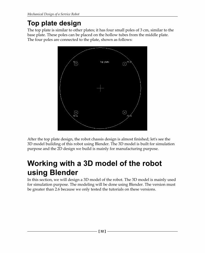
Top plate designThe top plate is similar to other plates; it has four small poles of 3 cm, similar to the base plate. These poles can be placed on the hollow tubes from the middle plate. The four poles are connected to the plate, shown as follows:
After the top plate design, the robot chassis design is almost fi nished; let's see the 3D model building of this robot using Blender. The 3D model is built for simulation purpose and the 2D design we build is mainly for manufacturing purpose.
Working with a 3D model of the robot using BlenderIn this section, we will design a 3D model of the robot. The 3D model is mainly used for simulation purpose. The modeling will be done using Blender. The version must be greater than 2.6 because we only tested the tutorials on these versions.

Chapter 2
[ 33 ]
The following screenshot shows the blender workspace and tools that can be used to work with 3D models:
The main reason why we are using Blender here is so that we can model the robot using Python scripts. Blender has an inbuilt Python interpreter and a Python script editor for coding purpose. We are not discussing about the user interface of Blender here. We can fi nd a good tutorial of Blender on its website. Refer to the following link to learn about Blender's user interface:
http://www.blender.org/support/tutorials/
Let's start coding in Blender using Python.
Python scripting in BlenderBlender is mainly written in C, C++, and Python. Users can write their own Python script and access all the functionalities of Blender. If you are an expert in Blender Python APIs, you can model the entire robot using a Python script instead of manual modeling.

Mechanical Design of a Service Robot
[ 34 ]
Blender uses Python 3.x. Blender. Python API is generally stable, but some areas are still being added to and improved. Refer to http://www.blender.org/documentation/blender_python_api_2_69_7/ for the documentation on Blender Python API.
Let's discuss Blender Python APIs that we will use in our robot model script.
Introduction to Blender Python APIsPython APIs in Blender can do most of the functionalities of Blender. The main jobs that can be done by these APIs are as follows:
• Edit any data inside Blender, such as scenes, meshes, particles, and so on• Modify user preference, key maps, and themes• Create new Blender tools• Draw the 3D view using OpenGL commands from Python
Blender provides the bpy module to the Python interpreter. This module can be imported in a script and gives access to blender data, classes, and functions; scripts that deal with Blender data will need to import this module. The main Python modules we will use in bpy are:
• Context Access: This provides access to Blender user interface functions from the (bpy.context) script.
• Data Access: This provides access to the Blender internal data (bpy.data).• Operators: This provides Python access to calling operators, which includes
operators written in C, Python, or Macros (bpy.ops).

Chapter 2
[ 35 ]
For switching to scripting in Blender, we need to change the screen layout of Blender. The following screenshot shows the option that helps you to switch to Scripting layout:
After selecting the Scripting tab, we can see a text editor and Python console window in Blender. In the text editor, we can code using Blender APIs and also try Python commands via the Python console. Click on the New button to create a new Python script and name it robot.py. Now, we can design the 3D model of robot using only Python scripts. The upcoming section has the complete script to design our robot model. We can discuss the code before running it. We hope you have read the Python APIs of Blender from their site. The code in the upcoming section is split into six Python functions to draw three robot plates, draw motors and wheels, draw four support tubes, and export into the STereoLithography (STL) 3D fi le format for simulation.

Mechanical Design of a Service Robot
[ 36 ]
Python script of the robot modelThe following is the Python script of the robot model that we will design:.
1. Before starting Python script in Blender, we must import the bpy module. The bpy module contains all the functionalities of Blender and it can only be accessed from inside the Blender application:import bpy
2. This following function will draw the base plate of the robot. This function will draw a cylinder with a radius of 5 cm and cut a portion from the opposite sides so that motors can be connected using the Boolean modifi er inside Blender:#This function will draw base platedef Draw_Base_Plate():
3. The following two commands will create two cubes with a radius of 0.05 meter on either side of the base plate. The purpose of these cubes is to create a modifi er that subtracts the cubes from the base plate. So in effect, we will get a base plate with two cuts. After cutting the two sides, we will delete the cubes: bpy.ops.mesh.primitive_cube_add(radius=0.05, location=(0.175,0,0.09)) bpy.ops.mesh.primitive_cube_add(radius=0.05, location=(-0.175,0,0.09)) #################################################### #################################################### #Adding base plate bpy.ops.mesh.primitive_cylinder_add(radius=0.15, depth=0.005, location=(0,0,0.09)) #Adding boolean difference modifier from first cube bpy.ops.object.modifier_add(type='BOOLEAN') bpy.context.object.modifiers["Boolean"].operation = 'DIFFERENCE' bpy.context.object.modifiers["Boolean"].object = bpy.data.objects["Cube"] bpy.ops.object.modifier_apply(modifier="Boolean")

Chapter 2
[ 37 ]
###################################################### ######################################################
#Adding boolean difference modifier from second cube bpy.ops.object.modifier_add(type='BOOLEAN') bpy.context.object.modifiers["Boolean"].operation = 'DIFFERENCE' bpy.context.object.modifiers["Boolean"].object = bpy.data.objects["Cube.001"] bpy.ops.object.modifier_apply(modifier="Boolean") ####################################################### ####################################################### #Deselect cylinder and delete cubes bpy.ops.object.select_pattern(pattern="Cube") bpy.ops.object.select_pattern(pattern="Cube.001") bpy.data.objects['Cylinder'].select = False bpy.ops.object.delete(use_global=False)
4. The following function will draw the motors and wheels attached to the base plate:#This function will draw motors and wheelsdef Draw_Motors_Wheels():
5. The following commands will draw a cylinder with a radius of 0.045 and 0.01 meter in depth for the wheels. After creating the wheels, it will be rotated and translated into the cut portion of the base plate: #Create first Wheel bpy.ops.mesh.primitive_cylinder_add(radius=0.045, depth=0.01, location=(0,0,0.07)) #Rotate bpy.context.object.rotation_euler[1] = 1.5708 #Transalation bpy.context.object.location[0] = 0.135

Mechanical Design of a Service Robot
[ 38 ]
#Create second wheel bpy.ops.mesh.primitive_cylinder_add(radius=0.045, depth=0.01, location=(0,0,0.07)) #Rotate bpy.context.object.rotation_euler[1] = 1.5708 #Transalation bpy.context.object.location[0] = -0.135
6. The following code will add two dummy motors to the base plate. The dimensions of motors are mentioned in the 2D design. The motor is basically a cylinder and it will be rotated and placed in the base plate: #Adding motors bpy.ops.mesh.primitive_cylinder_add(radius=0.018, depth=0.06, location=(0.075,0,0.075)) bpy.context.object.rotation_euler[1] = 1.5708 bpy.ops.mesh.primitive_cylinder_add(radius=0.018, depth=0.06, location=(-0.075,0,0.075)) bpy.context.object.rotation_euler[1] = 1.5708
7. The following code will add a shaft to the motors, similar to the motor model; the shaft is also a cylinder and it will be rotated and inserted into the motor model: #Adding motor shaft bpy.ops.mesh.primitive_cylinder_add(radius=0.006, depth=0.04, location=(0.12,0,0.075)) bpy.context.object.rotation_euler[1] = 1.5708 bpy.ops.mesh.primitive_cylinder_add(radius=0.006, depth=0.04, location=(-0.12,0,0.075)) bpy.context.object.rotation_euler[1] = 1.5708 ####################################################### #######################################################
8. The following code will add two caster wheels on the base plate. Currently, we are adding a cylinder as wheel. In the simulation, we can assign it as a wheel: #Adding Caster Wheel bpy.ops.mesh.primitive_cylinder_add(radius=0.015, depth=0.05, location=(0,0.125,0.065)) bpy.ops.mesh.primitive_cylinder_add(radius=0.015, depth=0.05, location=(0,-0.125,0.065))
Chapter 2
[ 39 ]
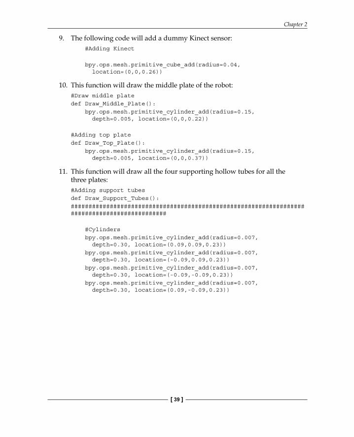
9. The following code will add a dummy Kinect sensor: #Adding Kinect bpy.ops.mesh.primitive_cube_add(radius=0.04, location=(0,0,0.26))
10. This function will draw the middle plate of the robot:#Draw middle platedef Draw_Middle_Plate(): bpy.ops.mesh.primitive_cylinder_add(radius=0.15, depth=0.005, location=(0,0,0.22))
#Adding top platedef Draw_Top_Plate(): bpy.ops.mesh.primitive_cylinder_add(radius=0.15, depth=0.005, location=(0,0,0.37))
11. This function will draw all the four supporting hollow tubes for all the three plates:#Adding support tubesdef Draw_Support_Tubes():############################################################################################# #Cylinders bpy.ops.mesh.primitive_cylinder_add(radius=0.007, depth=0.30, location=(0.09,0.09,0.23)) bpy.ops.mesh.primitive_cylinder_add(radius=0.007, depth=0.30, location=(-0.09,0.09,0.23)) bpy.ops.mesh.primitive_cylinder_add(radius=0.007, depth=0.30, location=(-0.09,-0.09,0.23)) bpy.ops.mesh.primitive_cylinder_add(radius=0.007, depth=0.30, location=(0.09,-0.09,0.23))

Mechanical Design of a Service Robot
[ 40 ]
12. This function will export the designed robot to STL. We have to change the STL fi le path before executing the script:#Exporting into STL def Save_to_STL(): bpy.ops.object.select_all(action='SELECT')# bpy.ops.mesh.select_all(action='TOGGLE') bpy.ops.export_mesh.stl(check_existing=True, filepath="/home/lentin/Desktop/exported.stl", filter_glob="*.stl", ascii=False, use_mesh_modifiers=True, axis_forward='Y', axis_up='Z', global_scale=1.0)
#Main code
if __name__ == "__main__": Draw_Base_Plate() Draw_Motors_Wheels() Draw_Middle_Plate() Draw_Top_Plate() Draw_Support_Tubes() Save_to_STL()
13. After entering the code in the text editor, execute the script by pressing the Run Script button, as shown in the following screenshot. The output 3D model will be shown on the 3D view of Blender. Also, if we check the desktop, we can see the exported.stl fi le for the simulation purposes:

Chapter 2
[ 41 ]
The exported.stl fi le can be opened with MeshLab and the following is a screenshot of MeshLab:
Downloading the example codeYou can download the example code fi les for all Packt books you have purchased from your account at http://www.packtpub.com. If you purchased this book elsewhere, you can visit http://www.packtpub.com/support and register to have the fi les e-mailed directly to you.
Questions1. What is robot modeling and what are its uses?2. What is the aim of 2D robot model?3. What is the aim of 3D robot model?4. What is the advantage of Python scripting over manual modeling?

Mechanical Design of a Service Robot
[ 42 ]
SummaryThis chapter was mainly aimed at robot mechanical designing. It also included the robot parameter calculation and robot chassis design. In robot designing, we fi rst need to have the prerequisites ready. Once it's ready, we can calculate the requirements of the components to be used in the robot. After the component requirements are met, we design the robot chassis according to the given requirements. The robot chassis design involves 2D design of all the parts required to build the robot. After 2D designing, we saw how to build the 3D robot model using Blender and Python script. The 3D model was built using the dimensions that we used in 2D drawing. We also covered the Blender Python script to build the entire 3D model. In this chapter, we got the design of the robot that can be used to manufacture it, and also developed a 3D model for simulation. In the next chapter, we will discuss the simulation of this robot model and some popular simulation tools.

Where to buy this book You can buy Learning Robotics Using Python from the Packt Publishing website. Alternatively, you can buy the book from Amazon, BN.com, Computer Manuals and most internet book retailers.
Click here for ordering and shipping details.
www.PacktPub.com
Stay Connected:
Get more information Learning Robotics Using Python