learning system dynamics: transfer of training in a ... · american institute of aeronautics and...
TRANSCRIPT

American Institute of Aeronautics and Astronautics
1
Learning System Dynamics: Transfer of Training in a Helicopter Hover Simulator
H.-G. Nusseck1, H.J. Teufel2, F.M. Nieuwenhuizen3 and H.H. Bülthoff4 Max Planck Institute for Biological Cybernetics, Tübingen, Germany
Transfer of training between the simulation of an inert and an agile helicopter dynamic was assessed involving a quasi-transfer design. The focus of this study was to test the ability of flight-naïve subjects to successfully acquire and transfer the skills required to perform lateral sidestep hover maneuvers in a helicopter simulation. The experiments were performed using the MPI Motion Simulator with its ability to realize a highly realistic 1:1 motion representation of a simulated helicopter maneuver. As a result, the amount of training needed to stabilize either an agile or an inert helicopter dynamic did not differ. A clear positive transfer effect was found for the acquired skills from the agile to the inert dynamics but not from the inert to the agile dynamics.
I. Introduction EARNING to stabilize a helicopter while hovering is one of the most challenging aspects of helicopter training. Because helicopters are intrinsically unstable systems, continuous active control is required to maintain stable
helicopter position and orientation. The highly nonlinear system dynamics include latencies between the control input and the consequences of that input. Therefore, a skilled pilot must attain helicopter stabilization using feed forward adjustments. To learn how to adequately stabilize the system, a pilot in training must learn how to effectively control the system. Based on the complexity of the helicopter dynamics, a novice pilot is naïve to the concrete system dynamics and of its parameters. The particular system dynamics are highly dependent on the type of helicopter: heavy helicopters with more inert dynamics need different control input characteristics than lightweight helicopters with agile system dynamics. When changing between different helicopter types, a pilot has to adapt his control policy to the changed system behavior through a learning process.
Simulators are a common part of the rotary-wing flight training procedures in military, commercial and private flight schools. Many of them are fixed base simulators. They are frequently used for mission training (e.g., navigational tasks) and for instrumental or handling training to gain familiarity with the cockpit instruments and the control inputs.
Currently, there is a strong discussion about the need of motion bases in helicopter training simulation. Several studies in the area of aviation flight simulation examined the effect of simulator motion in recurrent training. They found that in the presence of a sufficient visualization system the motion provided by a six-degree-of-freedom motion system provides only minimal benefits on training.1 A meta-analysis by Vaden et al. also suggests only a small positive performance benefit for pilot simulator training when simulator platform motion is included.2 On the other side, simulator motion does improve performance during hover training3,4 and motion cues may be beneficial under certain conditions like engine failures or turbulences. However, after analyzing the existing literature, McCauley concluded that “there is virtually no scientific evidence to support the effectiveness of motion platforms for training”.5
Motion simulators are widely used as part of pilot training in aviation. An optimal helicopter simulator should react and behave like a real helicopter (and should also “look, taste and smell like a helicopter”).6 Because of the 1 VR-system Administrator, Max Planck Institute for Biological Cybernetics, P.O. Box 2169, 72012 Tübingen, Germany; [email protected]. 2 Research Associate, Max Planck Institute for Biological Cybernetics, P.O. Box 2169, 72012 Tübingen, Germany; [email protected]. 3 Ph.D. student, Department Max Planck Institute for Biological Cybernetics, P.O. Box 2169, 72012 Tübingen, Germany; [email protected]. Student member AIAA. 4 Professor and Director, Department Max Planck Institute for Biological Cybernetics, P.O. Box 2169, 72012 Tübingen, Germany; [email protected]. Member AIAA
L
AIAA Modeling and Simulation Technologies Conference and Exhibit18 - 21 August 2008, Honolulu, Hawaii
AIAA 2008-7107
Copyright © 2008 by Max Planck Institute for Biological Cybernetics. Published by the American Institute of Aeronautics and Astronautics, Inc., with permission.
American Institute of Aeronautics and Astronautics
2
more inert dynamic of most fixed wing airplanes, the simulation is more feasible in a realistic manner than for the more complex dynamics of helicopters. Based on physical restrictions, a simulator can never move like a real helicopter. The visual motion can be simulated very well by state-of-the-art visualization systems, but based on the physical limitations of motion systems, the vestibular and somato-sensory senses cannot be simulated to the full extent. Compared to the capability of standard Stewart based flight simulators, the large motion range of the MPI Motion Simulator offers the possibility to let the simulator move and behave more similarly to a real helicopter. In particular, the MPI Motion Simulator has the potential to provide realistic helicopter flight dynamics without requiring motion cueing algorithms.
In the current study, a quasi-transfer design, with two different helicopter dynamics (agile and inert) was used to examine transfer of training effects. Quasi-transfer studies employ tasks where participants alternate between different simulators or where some change in task is performed in the same simulated environment.7 In contrast, real-flight-transfer studies investigate whether certain skills can be acquired in a simulator and successfully transferred to actual flight.
Holding states that “Transfer of training occurs whenever the effect of prior learning influences the performance of a later activity.”8 Transfer may be either positive or negative, the former occurring when performance is aided by the acquisition of skills on a prior task, the latter being the reverse effect with adverse interference caused by prior knowledge.
The focus of this study was to test the ability of flight-naïve subjects to successfully acquire and transfer the skills required to stabilize a helicopter and to perform lateral sidestep hover maneuvers. To our knowledge, no study was able to show a clear and reliable flight-transfer effect of helicopter hover training simulations. The outcome of this study may provide new insights to the ongoing discussion about the needs of real motion cues for flight training. This paper addresses two open questions. First, are there differences in the learning time between different helicopter dynamics? Second, does learning to control one set of helicopter dynamics affect the learning of new helicopter dynamics, i.e., is there transfer of training? To investigate these questions, we used a roll-lateral side-step maneuver analogous to the experiments of Schroeder9 and Beykirch et al.10,11. The sidestep maneuver was selected as a controlled small lateral movement followed by a hovering period is one of the most challenging aspects of helicopter flying.
II. Method It has been suggested that the use of ‘ab initio’ (flight-naïve) participants in training transfer research has the
capacity to reveal underlying transfer relationships without the interfering effect of prior experience.7 Therefore naïve participants without any flight experience or experience with flight training simulators were chosen to participate in this experiment.
In total, 20 subjects participated in the experiment (12 male and 8 female, ranging in age range from 17 to 37, with an average of 21.7). Verbal and written instructions were presented prior to the start of the experiment. The subjects were not informed about the background or motivation for the experiment. Specifically, no information about the change of helicopter dynamics was given.
The experiment consisted of three phases:
• Phase 1: Acquisition phase with either agile or an inert helicopter dynamics.
• Phase 2: Transfer phase with the other helicopter type.
• Phase 3: Back-Transfer phase with helicopter type from Phase 1.
Participants were randomly allocated to one of two experimental groups (counterbalanced by gender). One group began the training with a simulated agile (light) helicopter dynamic for the acquisition phase and then performed the inert (heavy) dynamic for the transfer phase followed by a back-transfer phase with again the agile dynamic (AIA-Group). The other group began with the inert helicopter dynamics, followed by the agile dynamic for the transfer phase and was again tested on the inert dynamics for the back-transfer phase (IAI-Group). Each phase was performed until a particular performance criterion was reached.
A. Performance measurements Analogous to the training in the experiment of Beykirch et al.10,11, performance was calculated using a
combination of the time needed to reach the target and the lateral and roll deviations during the 5 sec hovering period. A data set, collected during the design phase of the experiment, was used to scale the performance of the participants such that a value of 100% corresponds to the best average performance of well-trained participants. For
American Institute of Aeronautics and Astronautics
3
this task, the performance was similar to the one of an experienced helicopter instructor with more than 8500 hours of flight experience.
The performance of each subject was calculated from a combination of the time needed to reach a stable position and from stabilization accuracy during the 5 second hover phase at the target. The stabilization accuracy was measured by the variability (RMS) of the lateral position (in this simulation axis 1 of the robot arm) and the variability (RMS) of the roll angle (axis 6 of the robot arm). As discussed above, the data of the expert pilot served as standard value by 100% performance. Each performance criterion was calculated individually hence each trial results in a relative performance for time, lateral stability and roll stability (Ptime, Plateral and Proll) within a range from 0% to 100%. In more detail, the score was linearly scaled in the range of two standard deviations around the expert value. The overall total performance (Ptot) was calculated by combining the weighted single performances by the formula
rolllateraltimetot PPPP 41
41
21 ++= (1)
The weights were chosen such that the total performance was based equally on time and stability. The weight for stability was subdivided in lateral and roll variability with equal weighting.
The experimental procedure was divided into blocks of 12 trials. The average performance of each block was calculated by the mean of the 12 individual trials within the block. Each experimental phase was finished when the subjects reached a performance (Ptot) of more than 70% within two subsequent blocks. This criterion was selected based on the results from several measurements during the design phase of the experiment and correlates well with the subjective evaluation of hover performance by the instructors.
All trials were conducted in the same simulator environment. It is well-known that if several instructors are involved, variations can exist in students’ flight performance depending on the instructor.13,14 To prevent this type of effect, all participants were supervised by the same instructor. The performances (Ptime, Plateral, Proll) were computed after each block. Instructions were given to the participants only if the individual performance values lagged behind the others or when clearly bad strategies of the participants required this intervention. We did not give a performance feedback any each block or session.
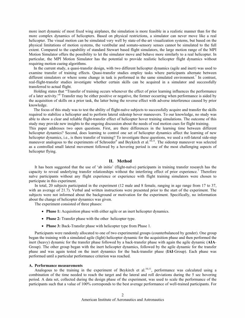
Figure 1. MPI Motion Simulator with a participant and the target lamps. This picture shows exactly the employed simulation environment. Room light condition was set to normal indoor intensity.
B. Setup The experiment was performed using the MPI Motion Simulator15, see Fig. 1, which is based on a 3-2-1 serial
robot (Kuka Roboter GmbH, Germany). The simulator has the capability of moving along all six degrees of freedom. For this experiment, however, the movement was restricted to roll motions (Axis 6) and to translations along an arc using the axis of rotation of the simulator base (Axis 1). Pitch remained zero over the experiment. Because lateral movement was on an arc, the yaw angle was deduced from Axis 1 (see Fig. 3). As a result, a reduced helicopter dynamic with only two degrees of freedom (DOF) and one actuated DOF was simulated. The vehicle
American Institute of Aeronautics and Astronautics
4
dynamics from the simulated helicopter had a 1:1 mapping to the Motion Simulator; hence no motion cueing algorithms were needed to scale down the movement to fit within the simulator workspace. The roll angle was controlled by the cyclic stick input of the pilot and the lateral dynamics followed from the roll angle. These simplified helicopter dynamics should serve as a baseline to assess the usability of robot arm based simulators for helicopter pilot training. A goal of subsequent research will be to simulate the full 6-DOF dynamics of a helicopter.
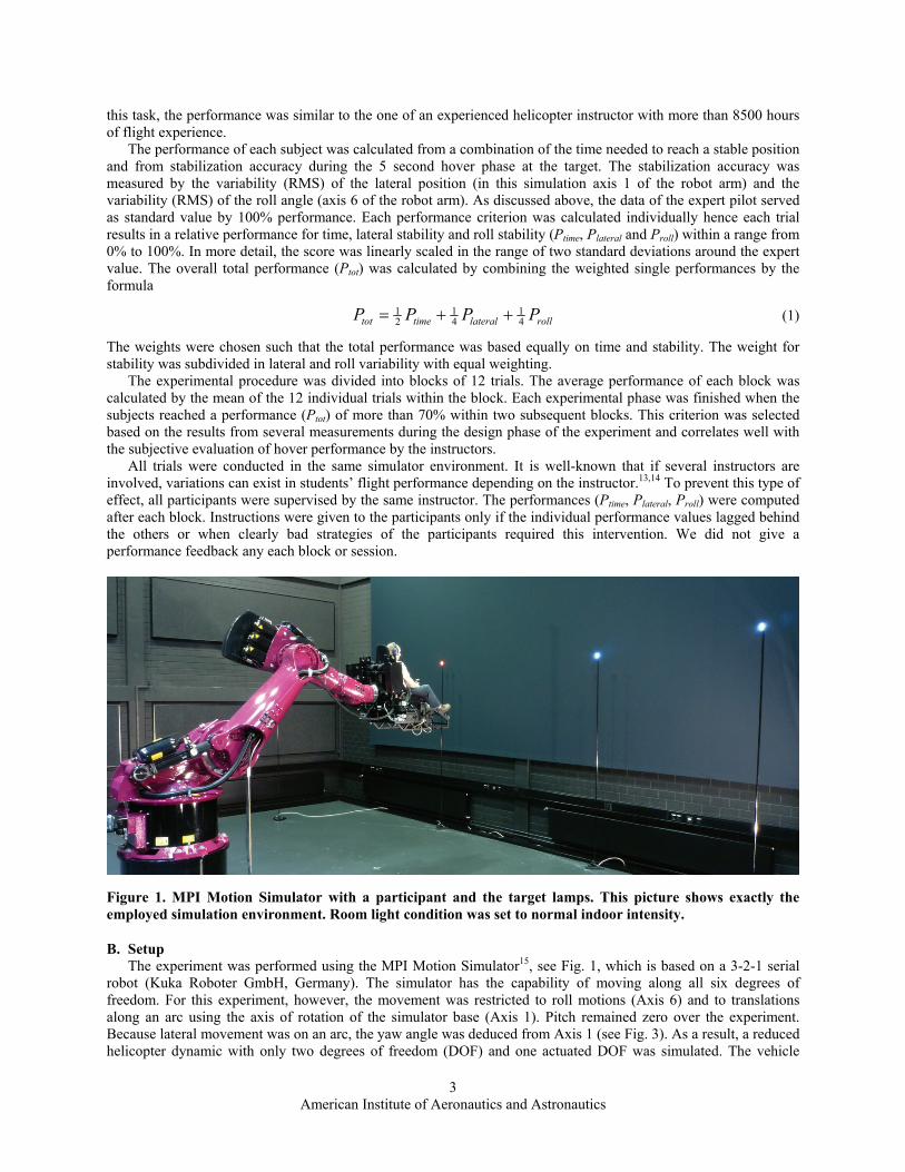
Analogous to the studies of Beykirch et al.10,11, participants were asked to perform constant-altitude roll-lateral side-step maneuvers, see Fig. 2, between several targets positioned along an arc. No visualization system (i.e., HMD or projectors) was used to present the visual targets. Instead, LED-based lamps on stands inside the simulation hall were used as ‘real world’ targets. This ‘real-world’ visualization ensures that no conflict between the visual and the vestibular system was introduced by the simulation. The perceived body motion was always identical to the perceived visual motion.
Figure 2. Illustration of a helicopter roll-lateral sidestep maneuver (top) and the appropriated simulator
movement (bottom).
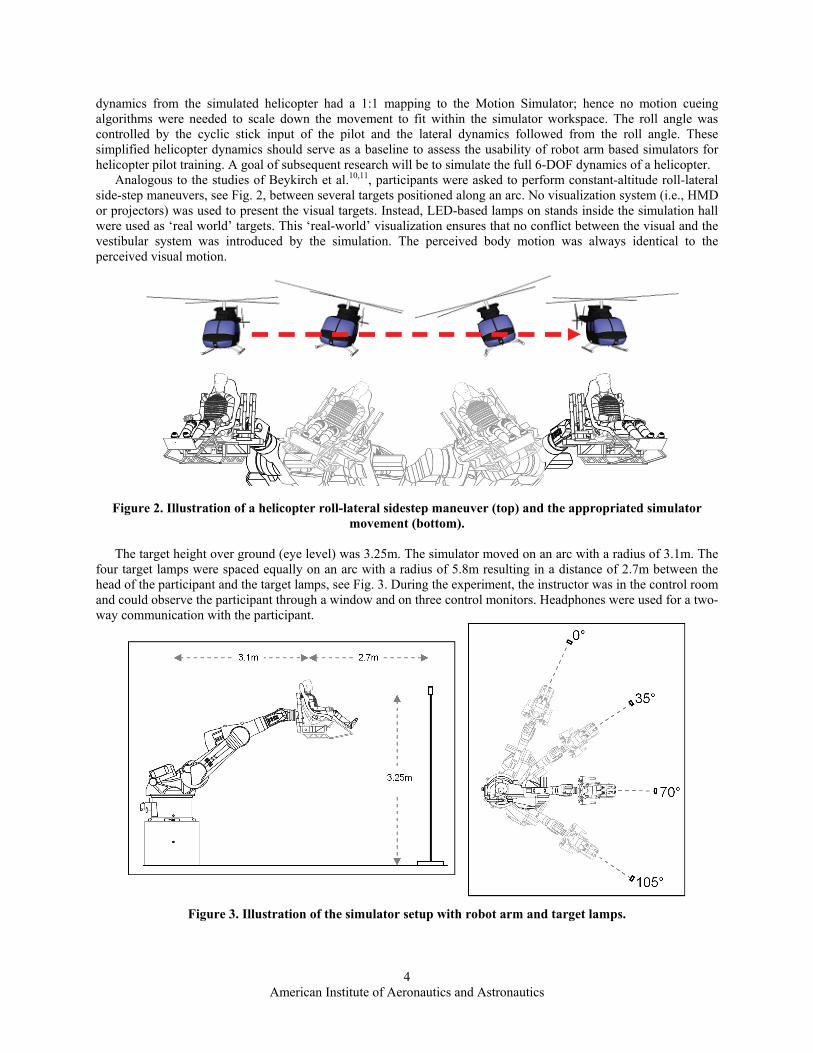
The target height over ground (eye level) was 3.25m. The simulator moved on an arc with a radius of 3.1m. The four target lamps were spaced equally on an arc with a radius of 5.8m resulting in a distance of 2.7m between the head of the participant and the target lamps, see Fig. 3. During the experiment, the instructor was in the control room and could observe the participant through a window and on three control monitors. Headphones were used for a two-way communication with the participant.
Figure 3. Illustration of the simulator setup with robot arm and target lamps.
American Institute of Aeronautics and Astronautics
5
C. Procedure Left and right side-steps with different distances were performed in a random order. The participants were
instructed to translate from a starting position to a particular target and then indicate when they were hovering stably in front of the target by pressing a button on the cyclic control stick. After this, the participants were required to hover stably in front of the target for 5 seconds. Subsequently the target disappeared and a new target flashed either to the left or to the right. Participants had to perform a side-step in order to get to the new target position.
Each block consisted of 12 side-step maneuvers. Using four target-lamps equally spaced on an arc resulted in 3 different distances of the lateral sidesteps (35°, 70° and 105° or 1,9m, 3,8m or 5,7m lateral movement), each with two possible directions. This number of six direction-distance combinations was repeated twice in each block of 12 sidesteps in random order. The participants’ objective was to optimize the accuracy and time to reach a stable state in front of each target.
In addition to the instructions, some hints and repetitions of the instructions were provided if necessary. The additional hints were given in writing in a standardized way. Some typical instructions and also the brief instruction can be found in the Appendix.
To prevent fatigue, an interleaved subject design was chosen where always two subjects participated at the experiment at the same time with interleaved sessions. While one participant was performing the experiment, the other participant took a break but was never provided with feedback nor able to watch the other participant.
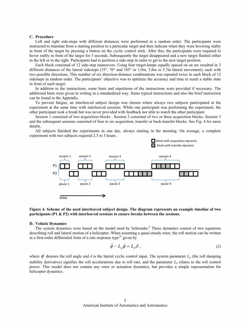
Session 1 consisted of two acquisition blocks . Session 2 consisted of two or three acquisition blocks. Session 3 and the subsequent sessions consisted of four to six acquisition, transfer or back-transfer blocks. See Fig. 4 for more details.
All subjects finished the experiments in one day, always starting in the morning. On average, a complete experiment with two subjects required 2.5 to 3 hours.
Figure 4. Scheme of the used interleaved subject design. The diagram represents an example timeline of two participants (P1 & P2) with interleaved sessions to ensure breaks between the sessions.
D. Vehicle Dynamics The system dynamics were based on the model used by Schroeder.9 These dynamics consist of two equations
describing roll and lateral motion of a helicopter. When assuming a quasi-steady rotor, the roll motion can be written in a first-order differential form of a rate response type16 given by
δφφ δLLp =− &&& , (2)
where φ denotes the roll angle and δ is the lateral cyclic control input. The system parameter Lp (the roll damping stability derivative) signifies the roll accelerations due to roll rate, and the parameter Lδ relates to the roll control power. This model does not contain any rotor or actuation dynamics, but provides a simple representation for helicopter dynamics.
P1
P2
time
block with acquisition dynamic block with transfer dynamic
session 1 session 2 session 3 session 4
pause 1 pause 2 pause 3 pause 4
American Institute of Aeronautics and Astronautics
6
The lateral degree of freedom is fully coordinated with the roll angle and is calculated using the following equation
φθ sing=&& , (3)
where θ is the rotation along the simulator base and g is the gravity constant estimated as 9.81 m/s2. In order to create two system dynamics (inert and agile), two different values were used for the roll damping
stability derivative. A value of -4.5/sec was taken from previous work by Schroeder9 and represents a responsive (agile) helicopter. In order to create a much more inert helicopter dynamics a value of -12.0/sec was chosen that the roll damping is much higher and thus the helicopter response is slower.
The roll control power did not differ between the two helicopter dynamics and was set to 12.5 rad/sec2. Note that the control input from the lateral direction of the cyclic stick has normalized output between -1 to 1.
The value for the roll control power was chosen by subjective estimation of two experienced helicopter pilots. Both pilots stated that 12.5 rad/sec2 for the roll control power adequately represented the dynamics of both the agile and the inert helicopter.
The first differential equation for the roll movement was solved numerically using the Runge-Kutta-Nyström-algorithm. The second differential equation was integrated analytically and solved for each time step. The length of each time step was 12ms and was determined by the internal control frequency of the robot. Position commands were sent to the control unit of the robot at this rate.
In principle, the control algorithm of the robot incorporated a velocity and acceleration limitation that ensured that the two joints used in the experiment did not exceed their velocity and acceleration bounds. In practice, however, the output of the differential equations never exceeded the maximum values during the flight maneuvers and therefore the MPI Motion Simulator could perform the computed motion profile on a 1 to1 scale.
III. Results The stopping criterion was reached in two consecutive blocks with a performance level of more than 70%. Based
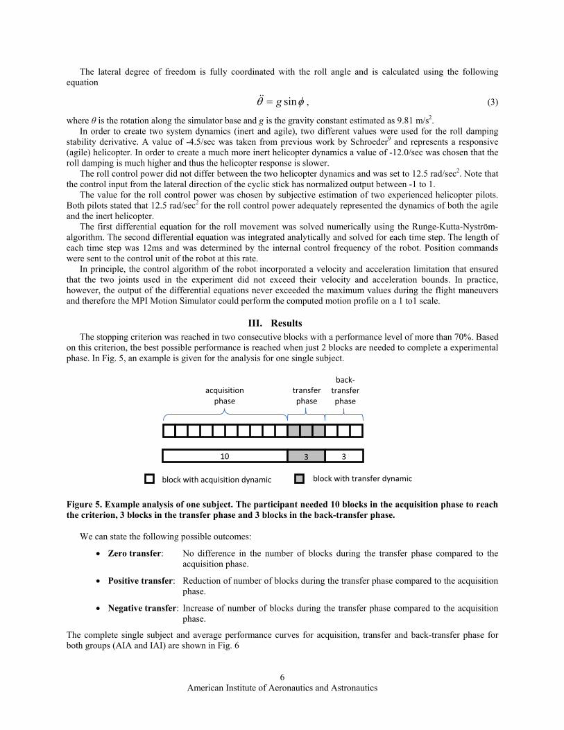
on this criterion, the best possible performance is reached when just 2 blocks are needed to complete a experimental phase. In Fig. 5, an example is given for the analysis for one single subject.
Figure 5. Example analysis of one subject. The participant needed 10 blocks in the acquisition phase to reach the criterion, 3 blocks in the transfer phase and 3 blocks in the back-transfer phase.
We can state the following possible outcomes:
• Zero transfer: No difference in the number of blocks during the transfer phase compared to the acquisition phase.
• Positive transfer: Reduction of number of blocks during the transfer phase compared to the acquisition phase.
• Negative transfer: Increase of number of blocks during the transfer phase compared to the acquisition phase.
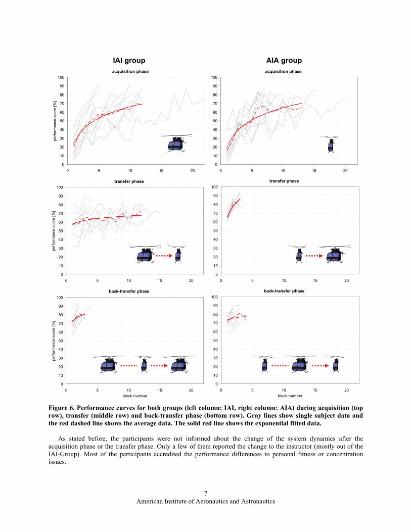
The complete single subject and average performance curves for acquisition, transfer and back-transfer phase for both groups (AIA and IAI) are shown in Fig. 6
3block with acquisition dynamic block with transfer dynamic
back‐transfer phase
transfer phase
acquisition phase
10 3 3
American Institute of Aeronautics and Astronautics
7
IAI group AIA group
acquisition phase
0
10
20
30
40
50
60
70
80
90
100
0 5 10 15 20
perfo
rman
ce-s
core
[%]
acquisition phase
0
10
20
30
40
50
60
70
80
90
100
0 5 10 15 20 transfer phase
0
10
20
30
40
50
60
70
80
90
100
0 5 10 15 20
perfo
rman
ce-s
core
[%]
transfer phase
0
10
20
30
40
50
60
70
80
90
100
0 5 10 15 20 back-transfer phase
0
10
20
30
40
50
60
70
80
90
100
0 5 10 15 20block number
perfo
rman
ce-s
core
[%]
back-transfer phase
0
10
20
30
40
50
60
70
80
90
100
0 5 10 15 20block number
Figure 6. Performance curves for both groups (left column: IAI, right column: AIA) during acquisition (top row), transfer (middle row) and back-transfer phase (bottom row). Gray lines show single subject data and the red dashed line shows the average data. The solid red line shows the exponential fitted data.
As stated before, the participants were not informed about the change of the system dynamics after the
acquisition phase or the transfer phase. Only a few of them reported the change to the instructor (mostly out of the IAI-Group). Most of the participants accredited the performance differences to personal fitness or concentration issues.
American Institute of Aeronautics and Astronautics
8
IAI - Group inert -> agile -> inert
5
5
8
9
10
10
11
12
12
22
4
4
4
2
6
12
10
15
13
9
2
2
3
4
2
3
2
2
3
3
10.40 7.90 2.60
0 5 10 15 20 25 30 35
MEAN
1
12
10
3
8
13
6
15
20
17
subj
ect
block number
IAI Group inert agile inert
0
2
4
6
8
10
12
14
acquisition transfer back‐transfer
phase
numbe
r of blocks
n.s.
**
p < 0.01
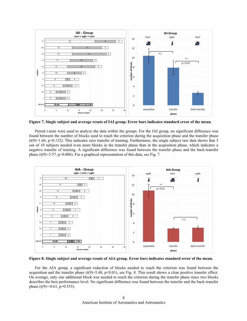
Figure 7. Single subject and average resuts of IAI group. Error bars indicates standard error of the mean.
Paired t-tests were used to analyze the data within the groups. For the IAI group, no significant difference was
found between the number of blocks used to reach the criterion during the acquisition phase and the transfer phase (t(9)=1.66, p=0.132). This indicates zero transfer of training. Furthermore, the single subject raw data shows that 3 out of 10 subjects needed even more blocks in the transfer phase than in the acquisition phase, which indicates a negative transfer of training. A significant difference was found between the transfer phase and the back-transfer phase (t(9)=3.57, p=0.006). For a graphical representation of this data, see Fig. 7.
AIA - Groupagile -> inert -> agile
7
7
7
8
9
10
12
13
15
20
3
3
3
3
3
3
3
3
2
2
2
2
3
4
4
2
3
4
2
4
10.80 2.80 3.00
0 5 10 15 20 25 30 35
MEAN
7
14
18
2
9
11
4
16
19
5
subj
ect
block number
AIA Group agile inert agile
0
2
4
6
8
10
12
14
acquisition transfer back‐transfer
phase
numbe
r of blocks
n.s.
**
p < 0.01
Figure 8. Single subject and average resuts of AIA group. Error bars indicates standard error of the mean.
For the AIA group, a significant reduction of blocks needed to reach the criterion was found between the
acquisition and the transfer phase (t(9)=5.48, p<0.01), see Fig. 8. This result shows a clear positive transfer effect. On average, only one additional block was needed to reach the criterion during the transfer phase since two blocks describes the best performance level. No significant difference was found between the transfer and the back-transfer phase (t(9)=-0.61, p=0.555).
American Institute of Aeronautics and Astronautics
9
0
2
4
6
8
10
12
14
acquisition transfer back‐transfer
phase
numbe
r of blocks
IAI (inert ‐ agile ‐ inert)
AIA (agile ‐ inert ‐ agile)
p < 0.01
**
n.s.
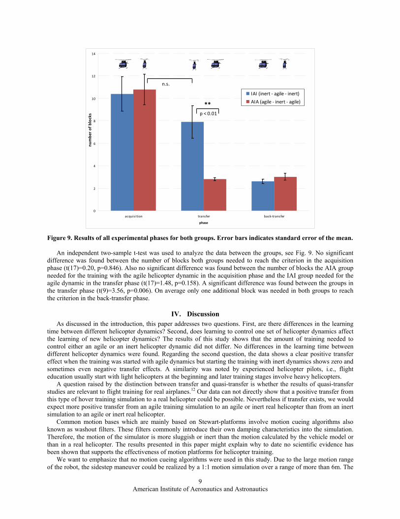
Figure 9. Results of all experimental phases for both groups. Error bars indicates standard error of the mean.
An independent two-sample t-test was used to analyze the data between the groups, see Fig. 9. No significant
difference was found between the number of blocks both groups needed to reach the criterion in the acquisition phase (t(17)=0.20, p=0.846). Also no significant difference was found between the number of blocks the AIA group needed for the training with the agile helicopter dynamic in the acquisition phase and the IAI group needed for the agile dynamic in the transfer phase (t(17)=1.48, p=0.158). A significant difference was found between the groups in the transfer phase (t(9)=3.56, p=0.006). On average only one additional block was needed in both groups to reach the criterion in the back-transfer phase.
IV. Discussion As discussed in the introduction, this paper addresses two questions. First, are there differences in the learning
time between different helicopter dynamics? Second, does learning to control one set of helicopter dynamics affect the learning of new helicopter dynamics? The results of this study shows that the amount of training needed to control either an agile or an inert helicopter dynamic did not differ. No differences in the learning time between different helicopter dynamics were found. Regarding the second question, the data shows a clear positive transfer effect when the training was started with agile dynamics but starting the training with inert dynamics shows zero and sometimes even negative transfer effects. A similarity was noted by experienced helicopter pilots, i.e., flight education usually start with light helicopters at the beginning and later training stages involve heavy helicopters.
A question raised by the distinction between transfer and quasi-transfer is whether the results of quasi-transfer studies are relevant to flight training for real airplanes.12 Our data can not directly show that a positive transfer from this type of hover training simulation to a real helicopter could be possible. Nevertheless if transfer exists, we would expect more positive transfer from an agile training simulation to an agile or inert real helicopter than from an inert simulation to an agile or inert real helicopter.
Common motion bases which are mainly based on Stewart-platforms involve motion cueing algorithms also known as washout filters. These filters commonly introduce their own damping characteristics into the simulation. Therefore, the motion of the simulator is more sluggish or inert than the motion calculated by the vehicle model or than in a real helicopter. The results presented in this paper might explain why to date no scientific evidence has been shown that supports the effectiveness of motion platforms for helicopter training.
We want to emphasize that no motion cueing algorithms were used in this study. Due to the large motion range of the robot, the sidestep maneuver could be realized by a 1:1 motion simulation over a range of more than 6m. The
American Institute of Aeronautics and Astronautics
10
large workspace and tremendous roll-tilt dynamics and range make the MPI motion simulator design very attractive not only for helicopter training.
In ongoing work, the authors will apply the method developed in this study to design a ‘real’ transfer experiment where the transfer of training will be assessed between a helicopter simulation and a real helicopter. This could verify the simulator effectiveness but also address the question whether effects similar to the effects presented here can be observed in real flight training.
Appendix: Participant’s briefing Thank you for participating in this experiment. You are free to quit the experiment at any time if you feel sick or
for any other reason.
Introduction The objective of the study is to investigate the learning of the stabilization skill in a simplified helicopter
simulation. The experiment will use the MPI Motion-Simulator which is behaving like a basic helicopter. The simulation is restricted to tilt movements and lateral side movements along an arc. The maximum amplitude
of each arc is limited to the range needed for the experiment. Thus, unlimited movement is not possible. The general task is to move the helicopter in front of a target and keep it stable in front of the target. The targets
are LED lights placed in the simulation hall and change automatically.
Helicopter Dynamics To move a helicopter from one position to another on must first tilt the helicopter so it starts accelerating in the
desired direction. To stop in front of the target position you have to initiate a tilt in the opposite direction in order to decelerate the helicopter. Finally the helicopter must be leveled out in order to maintain a stable position.
The tilt is controlled by the cyclic stick. Moving the cyclic stick to the right will initiate a roll movement to the right and vice-verse. Without a roll movement there will be no lateral movement. In other words all lateral movements are the result of rolling the helicopter using the cyclic stick. Without constant control the helicopter starts rolling automatically as the result of unstable system dynamics so one must control constantly to maintain stability.
Experimental Procedure After taking your place in the simulator and fastening the safety belt you will be taken to a starting position in
front of the LED lamps. Then, one lamp lights up which signals the start of the experiment. At this point you will gain control of the helicopter through the cyclic stick. Now try to bring yourself in front of the target. If you reach a stable position in front of the target press the trigger button located in front of your index finger on the cyclic stick. You will hear a sound and should maintain the stable position for a couple seconds until the lamp goes out. A new lamp will then light up and you should move toward that lamp. Once stable in front of the new lamp you repeat the procedure described previously.
In this experiment when we talk about a maintaining ‘a stable position in front of that target’ we mean that the pilot should have control of the helicopter to the best of his/her ability and be maintaining the position in front of the target. The helicopter does not need be perfectly still but should be kept near the front of the target.
The experiment is divided into blocks of twelve lamp changes. The task is to complete one block as fast as possible but also as accurately as possible. Accuracy is defined as proximity to the target as well as relative stability in front of the target.
Here are some hints:
1. Concentrate more on the roll than the lateral position and movement. Try first to keep the simulator in an upright position. Next, try to move laterally by controlled roll of the helicopter.
2. Keep a loose grip on the cyclic stick. Try to avoid fast and large movements.
3. Looking at or fixating the cyclic stick is not helpful. Try to look at the target lamps or the wall behind the target.
4. Try not to produce fast lateral velocities and balance quickness with accuracy. Fast lateral speeds can produce loss of control which then takes time to stabilize. Try to optimize the time to reach a stable position in front of the targets.
5. If the system starts oscillating one strategy to regain control is to leave the stick in a stable position for a brief period of time before trying to regain control of the helicopter.
American Institute of Aeronautics and Astronautics
11
6. Moving very slow to the target is of cause a strategy to prevent the loss of control. But we want you to be fast! Or in other words: Try to find your own speed as a balance between fastness and controllability.
7. The simulator motion is restricted on the left and right side of the arc. Some find it helpful to rest here before proceeding with the stabilizing tasks.
Now have fun with the experiment. If you have questions do not be afraid to ask us.
References 1Bürki-Cohen, J. and Go, T. H. "The Effect of Simulator Motion Cues on Initial Training of Airline Pilots," Proceedings of
the AIAA Modeling and Simulation Technologies Conference and Exhibit, San Francisco (CA), No. AIAA-2005-6109, Aug 15-18, 2005.
2Vaden, E.A. and Hall, S. "The Effect of Simulator Platform Motion on Pilot Training Transfer: A Meta-Analysis," The International Journal of Aviation Psychology, No. 15(4), p.375-393, 2005
3Terzibas, C. "Entwicklung eines Hubschraubersimulators zur Untersuchung der Lagestabilisierung mit visuellen und vestibulären Reizen auf einer Bewegungsplattform mit sechs Freiheitsgraden," Diploma Thesis, Oct 2004
4Berger, D. R., Terzibas, C., Beykirch, K., and Bülthoff, H. H., "The Role of Visual Cues and Whole-Body Rotations in Helicopter Hovering Control," Proceedings of the AIAA Modeling and Simulation Technologies Conference and Exhibit, Hilton Head (SC), No. AIAA-2007-6798, Aug 20-23, 2007.
5 McCauley, M.E. "Do Army Helicopter Training Simulators Need Motion Bases?," U.S. Army Research Institute for the Behavioral Sciences, Technical Report 1176, Arlington, VA, 2006.
6Dohme, J. "Transfer of Training and Simulator Qualification or Myth and Folklore in Helicopter Simulation," FAA Helicopter Simulator Workshop, p.115-121, NASA/N93-30687, 1993
7Taylor, H.L., Lintern G. and Koonce, J.M. "Quasi-Transfer as a Predictor of Transfer From Simulator to Airplane," The Journal of General Psychology, No. 120(3), p.257-276, 1993
8Holding (in "Training for Performance: Principles of Applied Human Learning," Wiley Series in Human Performance and Cognition, J. Ed p.93, 1991)
9Schroeder, J.A., "Helicopter Flight Simulation Motion Platform Requirements," NASA/TP-1999-208766, NASA, 1999. 10Beykirch, K., Nieuwenhuizen, F.M., Teufel, H.J., Nusseck, H.-G., Butler, J.S., and Bülthoff, H.H. "Control of a Lateral
Helicopter Side-step Maneuver on an Anthropomorphic Robot," Proceedings of the AIAA Modeling and Simulation Technologies Conference and Exhibit, Hilton Head (SC), No. AIAA-2007-6801, Aug 20-23, 2007.
11Beykirch, K.A., Nieuwenhuizen, F.M., Teufel, H.J., Nusseck, H.-G., and Bülthoff, H.H., "A Roll-Lateral Helicopter Side-Step Maneuver on the MPI Motion Simulator," Proceedings of the AHS 64th Annual Forum and Technology Display, Montréal (CA), Apr 2008.
13Lintern, G., Roscoe, S.N., and Sivier, J.E. "Display principle, control dynamics, and environmental factors in pilot training and transfer," Human Factors, 32, p.299-317, 1990.
14Hays, R.T. "The Science of Learning: A Systems Theory Approach, " BrownWalker Press, Dec 2006 15Teufel, H.J., Nusseck, H.-G., Beykirch, K.A., Butler, J.S., Kerger, M., and Bülthoff, H.H., "MPI Motion Simulator:
Development and Analysis of a Novel Motion Simulator," Proceedings of the AIAA Modeling and Simulation Technologies Conference and Exhibit, Hilton Head (SC), No. AIAA-2007-6476, Aug 20-23, 2007.
16Padfield, G.D., "Helicopter Flight Dynamics, Second Edition," AIAA Education Series, AIAA, New York, 2007.