lec-2281 & lec-2284 user manual - lanner inc. · embedded & industrial computing lec-2281...
TRANSCRIPT

Embedded & Industrial Computing
LEC-2281 & LEC-2284
User Manual
Rev 1.1 January 10th
, 2017

Embedded & Industrial Computing
Revision History
This document contains proprietary information of Lanner Electronics Inc. –and is not to be
disclosed or used except in accordance with applicable agreements.
Copyright © 2017. All Rights Reserved.
Copyright© 2017 Lanner Electronics Inc. All rights reserved. The information in this document
is proprietary and confidential to Lanner Electronics Inc. No part of this document may be
reproduced in any form or by any means or used to make any derivative work (such as
translation, transformation, or adaptation) without the express written consent of Lanner
Electronics Inc. Lanner Electronics Inc. reserves the right to revise this document and to make
changes in content from time to time without obligation on the part of Lanner Electronics Inc. to
provide notification of such revision or change.
The information in this document is furnished for informational use only, is subject to change
without notice, and should not be construed as a commitment by Lanner Electronics Inc. Lanner
Electronics Inc. assumes no responsibility or liability for any errors or inaccuracies that may
appear in this document or any software that may be provided in association with this document.
Rev Date Descriptions
0.1 2015/09/16 Preliminary
0.2 2016/01/27 Incorporated LEC-2284 model
0.3 2016/02/02 Added riser cards LEK-EA7 and LEK-PB6
1.0 2016/02/23 Official release
1.1 2017/01/10 Added serial configuration jumpers
Modified J2 PCIe jumper setting
Modified hardware installations

Embedded & Industrial Computing
Online Resources
The listed websites are links to the on-line product information and technical support.
Resource Website
Lanner www.lannerinc.com
Product Resources www.lannerinc.com/support/download-center
RMA http://eRMA.lannerinc.com
Acknowledgement
Intel, Pentium and Celeron are registered trademarks of Intel Corp.
Microsoft Windows and MS-DOS are registered trademarks of Microsoft Corp.
All other product names or trademarks are properties of their respective owners.
Compliances and Certification
CE Certification
This product has passed the CE test for environmental specifications. Test conditions for
passing included the equipment being operated within an industrial enclosure. In order to
protect the product from being damaged by ESD (Electrostatic Discharge) and EMI leakage,
we strongly recommend the use of CE-compliant industrial enclosure products.
FCC Class A Certification
This equipment has been tested and found to comply with the limits for a Class A digital device,
pursuant to Part 15 of the FCC Rules. These limits are designed to provide reasonable
protection against harmful interference when the equipment is operated in a commercial
environment. This equipment generates, uses and can radiate radio frequency energy and, if
not installed and used in accordance with the instruction manual, may cause harmful
interference to radio communications. Operation of this equipment in a residential area is likely
to cause harmful interference in which case the user will be required to correct the interference
at his own expense.
EMC Notice
This equipment has been tested and found to comply with the limits for a Class A digital device,
pursuant to Part 15 of the FCC Rules. These limits are designed to provide reasonable
protection against harmful interference when the equipment is operated in a commercial
environment. This equipment generates, uses, and can radiate radio frequency energy and, if

Embedded & Industrial Computing
not installed and used in accordance with the instruction manual, may cause harmful
interference to radio communications. Operation of this equipment in a residential area is likely
to cause harmful interference in which case users will be required to correct the interference at
their own expense.
Safety Guidelines
Follow these guidelines to ensure general safety:
Keep the chassis area clear and dust-free before, during and after installation.
Do not wear loose clothing or jewelry that could get caught in the chassis. Fasten your tie
or scarf and roll up your sleeves.
Wear safety glasses/goggles if you are working under any conditions that might be
hazardous to your eyes.
Do not perform any action that creates a potential hazard to people or makes the
equipment unsafe.
Disconnect all power by turning off the power and unplugging the power cord before
installing or removing a chassis or working near power supplies
Do not work alone if potentially hazardous conditions exist.
Never assume that power is disconnected from a circuit; always check the circuit.
LITHIUM BATTERY CAUTION:
Risk of explosion could occur if battery is replaced by an incorrect type. Please dispose of
used batteries according to the recycling instructions of your country.
Installation only by a trained electrician or only by an electrically trained person who knows
all the applied or related installation and device specifications..
Do not carry the handle of power supplies when moving to other place.
The machine can only be used in a fixed location such as labs or computer facilities.
Operating Safety
Electrical equipment generates heat. Ambient air temperature may not be adequate to
cool equipment to acceptable operating temperatures without adequate circulation. Be
sure that the room in which you choose to operate your system has adequate air
circulation.
Ensure that the chassis cover is secure. The chassis design allows cooling air to circulate
effectively. An open chassis permits air leaks, which may interrupt and redirect the flow of
cooling air from internal components.
Electrostatic discharge (ESD) can damage equipment and impair electrical circuitry. ESD
damage occurs when electronic components are improperly handled and can result in

Embedded & Industrial Computing
complete or intermittent failures. Be sure to follow ESD-prevention procedures when removing
and replacing components to avoid these problems.
Wear an ESD-preventive wrist strap, ensuring that it makes good skin contact. If no wrist
strap is available, ground yourself by touching the metal part of the chassis.
Periodically check the resistance value of the antistatic strap, which should be between 1
and 10 megohms (Mohms).
Mounting Installation Environment Precaution
1. Elevated Operating Ambient - If installed in a closed or multi-unit rack assembly, the
operating ambient temperature of the rack environment may be greater than room ambient.
Therefore, consideration should be given to installing the equipment in an environment
compatible with the maximum ambient temperature (Tma) specified by the manufacturer.
2. Reduced Air Flow - Installation of the equipment in a rack should be such that the amount of
air flow required for safe operation of the equipment is not compromised.
3. Mechanical Loading - Mounting of the equipment in the rack should be such that a
hazardous condition is not achieved due to uneven mechanical loading.
4. Circuit Overloading - Consideration should be given to the connection of the equipment to
the supply circuit and the effect that overloading of the circuits might have on over-current
protection and supply wiring. Appropriate consideration of equipment nameplate ratings
should be used when addressing this concern.
5. Reliable Earthing - Reliable earthing of rack-mounted equipment should be maintained.
Particular attention should be given to supply connections other than direct connections to the
branch circuit (e.g. use of power strips).”
Consignes de sécurité
Suivez ces consignes pour assurer la securite generale :
Laissez la zone du chassis propre et sans poussiere pendant et apres l’installation.
Ne portez pas de vetements amples ou de bijoux qui pourraient etre pris dans le chassis.
Attachez votre cravate ou echarpe et remontez vos manches.
Portez des lunettes de securite pour proteger vosmyeux.
N’effectuez aucune action qui pourrait creer un dangermpour d’autres ou rendre
l’equipement dangereux.
Coupez completement l’alimentation en eteignant l’alimentation et en debranchant le
cordon d’alimentation avant d’installer ou de retirer un chassis ou de travailler a proximite
de sources d’alimentation.
Ne travaillez pas seul si des conditions dangereuses sont presentes.

Embedded & Industrial Computing
Ne considerez jamais que l’alimentation est coupee d’un circuit, verifiez toujours le circuit.
Cet appareil genere, utilise et emet une energie radiofrequence et, s’il n’est pas installe et
utilise conformement aux instructions des fournisseurs de composants sans fil, il risque de
provoquer des interferences dans les communications radio.
Avertissement concernant la pile au lithium
Risque d’explosion si la pile est remplacee par une autre d’un mauvais type.
Jetez les piles usagees conformement aux instructions.
L’installation doit etre effectuee par un electr icien forme ou une personne formee a
l’electricite connaissant toutes les specifications d’installation et d’appareil du produit.
Ne transportez pas l’unite en la tenant par le cable d’alimentation lorsque vous deplacez
l’appareil.
La machine ne peut etre utilisee qu’a un lieu fixe comme en laboratoire, salle d’ordinateurs
ou salle de classe.
Sécurité de fonctionnement
L’equipement electrique genere de la chaleur. La temperature ambiante peut ne pas etre
adequate pour refroidir l’equipement a une temperature de fonctionnement acceptable
sans circulation adaptee. Verifiez que votre site propose une circulation d’air adequate.
Verifiez que le couvercle du chassis est bien fixe. La conception du chassis permet a l’air
de refroidissement de bien circuler. Un chassis ouvert laisse l’air s’echapper, ce qui peut
interrompre et rediriger le flux d’air frais destine aux composants internes.
Les decharges electrostatiques (ESD) peuvent endommager l’equipement et gener les
circuits electriques. Des degats d’ESD surviennent lorsque des composants electroniques
sont mal manipules et peuvent causer des pannes totales ou intermittentes. Suivez les
procedures de prevention d’ESD lors du retrait et du remplacement de composants.
- Portez un bracelet anti-ESD et veillez a ce qu’il soit bien au contact de la peau. Si aucun
bracelet n’est disponible, reliez votre corps a la terre en touchant la partie metallique du
chassis. Verifiez regulierement la valeur de resistance du bracelet antistatique, qui doit etre
comprise entre 1 et 10 megohms (Mohms).
Consignes de sécurité électrique
Avant d’allumer l’appareil, reliez le cable de mise a la terre de l’equipement a la terre.
Une bonne mise a la terre (connexion a la terre) est tres importante pour proteger l
equipement contre les effets nefastes du bruit externe et reduire les risques d’electrocution
en cas de foudre.
Pour desinstaller l’equipement, debranchez le cable de mise a la terre apres avoir eteint
l’appareil.

Embedded & Industrial Computing
Un cable de mise a la terre est requis et la zone reliant les sections du conducteur doit
faire plus de 4 mm2 ou 10 AWG.
Procédure de mise à la terre pour source
d’alimentation CC Procédure de mise à la terre pour
source d’alimentation CC
• Desserrez la vis du terminal de mise a la terre.
• Branchez le cable de mise a la terre a la terre.
• L’appareil de protection pour la source d’alimentation
CC doit fournir 30 A de courant. Cet appareil de protection doit etre branche a la source
d’alimentation avant l’alimentation CC.

Embedded & Industrial Computing
Table of Contents
Revision History ................................................................................................................. 2
Chapter 1: Introduction ...................................................................................................... 9
System Specification ................................................................................................10
Ordering Information ...............................................................................................12
Accessories ...............................................................................................................12
Package Contents .....................................................................................................12
Chapter 2: System Overview ...........................................................................................13
Mechanical Drawing (LEC-2281)...........................................................................13
Mechanical Drawing (LEC-2284)...........................................................................14
Block Diagram (LEC-2281) ....................................................................................15
Block Diagram (LEC-2284) ....................................................................................16
Front I/Os (LEC-2281) ............................................................................................17
Rear I/Os (LEC-2281)..............................................................................................18
Front I/Os (LEC-2284) ............................................................................................19
Rear I/Os (LEC-2284)..............................................................................................20
Chapter 3: Board Layout ..................................................................................................21
Jumpers and Connectors on the Motherboard ........................................................21
Jumpers and Connectors on the Add-on Board ......................................................22
Jumpers and Connectors on the Add-on Board ......................................................23
Jumpers and Connectors List...................................................................................25
Jumper Setting and Connector Pin-out ...................................................................26
Chapter 4: Hardware Setup ..............................................................................................39
Accessing the Inside of the System.........................................................................39
Installing the System Memory.................................................................................40
Installing a mSATA or Mini-PCIe module .............................................................41
Installing a Disk Drive for LEC-2281.....................................................................41
Installing a Disk Drive for LEC-2284.....................................................................43
Connecting Power ....................................................................................................44
Appendix1: Programming Watchdog Timer ...................................................................45

Embedded & Industrial Computing
Chapter 1: Introduction
Thank you for choosing LEC-2281/LEC-2284. This fanless embedded Box PC utilizes Intel
Haswell platform, with ordering options of Celeron 2000E, i3-4102E, i5-4400E, or i7-4700EQ.
The system supports DDR3L memory up to 16GB. Regarding peripheral connections,
LEC-2281/LEC-2284 supports multiple I/O features including 2 LAN ports (one with
iAMT/Teaming), 6 USB ports, 2 x mini-PCIe slots and two SATA 2.5” storage bays supporting
RAID 0 & 1. The rich I/O functionality makes LEC-2281/LEC-2284 an instant embedded
platform for various applications. Their major difference lies in physical size. For compact
applications, LEC-2281 is the ideal choice. For larger system with externally accessible disk
drives, LEC-2284 is the primary option.
Here is the summary of the key features:
On board Intel Haswell Family CPU: Celeron 2000E/ i3-4102E/ i5-4400E/ i7-4700EQ
Intel QM87 Chipset
Fanless System
2x DDR3L SO-DIMM support up to 16GB
2x 10/100/1000Mbps Ethernet ports (one support iAMT or Teaming)
2x USB3.0, 6x USB 2.0 (2x USB2.0 used onboard 2x5 pin header)
2x mini-PCIe sockets (one with SIM card reader)
Storage:
LEC-2281 Series: 2 x SATA 2.5” HDD/SSD drive bays
LEC-2284 Series: 2x SATA 2.5” HDD/SSD externally accessible drive bays
2x SATA 2.5”storage bay support RAID 0 &1 and 1 x mSATA socket
Support 9~30V wide range power input
External Expansion:
LEC-2281 series: 1x PCIe expansion slot; standard with x16 riser card, with 1x PCI
expansion slot (included in package)
LEC-2284 series: 2x PCIe expansion slot; standard with x8 riser card, with 2x PCI
expansion slot (included in package)
Please refer to the following chart for a detailed description of the system's specifications.

Embedded & Industrial Computing
System Specification
Processor Options Onboard Haswell processor:
Intel® Core™ i7-4700EQ (47W)
Intel® Core™ i5-4400E (37W)
Intel® Core™ i3-4102E (25W)
Intel® Celeron® Processor 2000E (37W)
Chipset Intel® QM87
BIOS AMI SPI 128Mbit Flash BIOS
System Memory 2x DDR3L SO-DIMM socket supports capacity up to
16GB (8GB for each socket)
@1333/1600MHz
USB 4 x USB 2.0 ports in double-stacked type-A
connector
2x USB 3.0 ports in double-stacked type-A
connector
1 x USB2.0 onboard pin header
OS Support Windows Embedded Standard 7, Windows 7 FES,
Windows Embedded 8.1 Industry Pro,Windows 10
IoT Enterprise 2016, Linux
Kernel 3.x
Storage 1 x mSATA socket
2 x 2.5” SATA HDD/SSD drive bays (Externally
accessible for LEC-2284)
Supports RAID 0/1
Networking LAN 2x RJ-45 of 10/100/1000Mbps Ethernet ports
(one with iAMT or Teaming)
Controller 1x Intel i217LM & 1x Intel i210AT
Serial Interface Serial Standard 2 x DB9 COM ports (with RS232/422/485)
Display Graphics
Controller
Intel integrated HD graphic engine 4600
Intel® HD Graphics (Intel® Celeron® Processor
2000E )
Dual Display
Function
Independent, clone, and extended mode
Output 1 x VGA port
1 x HDMI port
1 x DVI-D connector
Super I/O 1x LPC Super I/O Fintek F81866AD-I supporting

Embedded & Industrial Computing
Watchdog Timer, Hardware monitor,1x
Temperature monitor for internal system
Audio Realtek ALC886-GR
Mic-in, Line-out
Expansion Internal:
2x mini-PCIe slots (one with SIM card Reader)
External:
LEC-2281:
1x PCIe expansion slot; standard with x16 riser card
Option: 1x PCI expansion slot (included in package)
LEC-2284:
2x PCIe expansion slot; standard with x8 riser card
Option: 2x PCI expansion slot (included in package)
Antenna 2 x SMA antenna inputs
TPM TPM Pin header onboard
LED Indicator 2x LED for Power-on status(Green) and Storage
access status(Yellow)
Physical
Characteristics
Housing Made by Aluminum & SGCC
Thermal Fanless design
Dimensions 277 x 110 x 195 mm (10.9” x 4.33” x 7.68”)
Mounting Options Wallmount, VESA, Rackmoount
Weight 4.2 kg
Environment Operating
Temperature
-10°C to +50°C
Non-operating
Temperature
-20°C to +70°C
Ambient
Humidity
5 to 95% (non-condensing)
Vibration IEC 60068-2-64, 0.5Grms, Random 5 ~500 Hz, 40
Mins/Axis
Power Input Voltage 1x 2-pin terminal block for +9V~+30V DC input
Power
Consumption
Idle: 25.42W
Full Load: 36.22W
Power Button 1x Power-on button(Red-Stand by,
Green-Operating)
Reset 1x Reset Switch
Certifications EMC CE/FCC Class A
Embedded & Industrial Computing
Green product RoHS
Reliability Automatic
Reboot
Trigger
Watchdog Timer 1~255 level time interval
system reset, software programmable
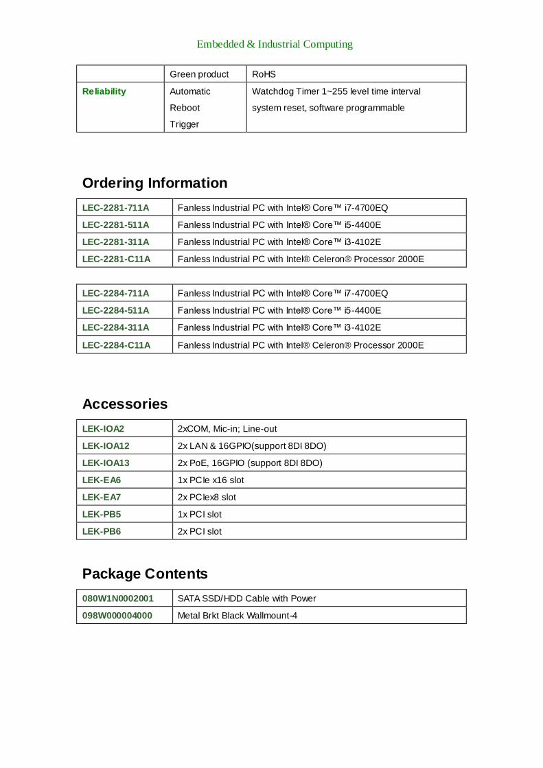
Ordering Information
LEC-2281-711A Fanless Industrial PC with Intel® Core™ i7-4700EQ
LEC-2281-511A Fanless Industrial PC with Intel® Core™ i5-4400E
LEC-2281-311A Fanless Industrial PC with Intel® Core™ i3-4102E
LEC-2281-C11A Fanless Industrial PC with Intel® Celeron® Processor 2000E
LEC-2284-711A Fanless Industrial PC with Intel® Core™ i7-4700EQ
LEC-2284-511A Fanless Industrial PC with Intel® Core™ i5-4400E
LEC-2284-311A Fanless Industrial PC with Intel® Core™ i3-4102E
LEC-2284-C11A Fanless Industrial PC with Intel® Celeron® Processor 2000E
Accessories
LEK-IOA2 2xCOM, Mic-in; Line-out
LEK-IOA12 2x LAN & 16GPIO(support 8DI 8DO)
LEK-IOA13 2x PoE, 16GPIO (support 8DI 8DO)
LEK-EA6 1x PCIe x16 slot
LEK-EA7 2x PCIex8 slot
LEK-PB5 1x PCI slot
LEK-PB6 2x PCI slot
Package Contents
080W1N0002001 SATA SSD/HDD Cable with Power
098W000004000 Metal Brkt Black Wallmount-4

Embedded & Industrial Computing
Chapter 2: System Overview
Mechanical Drawing (LEC-2281)
Unit: mm

Embedded & Industrial Computing
Mechanical Drawing (LEC-2284)
Unit: mm

Embedded & Industrial Computing
Block Diagram (LEC-2281)
1x mSATA Mini PCIe Slot
SATA II
PCIex2 GPIO SATA Serial
HDMI resolution: up to 4096x2304
Processor Intel Haswell
Series (BGA)
DDR3L 1333/1600 2x SO-DIMM up to 16G PCIe Expansion
For Riser Card
PCH QM87
VGA resolution: up to
1920x1200
SATA Connector 4x 6Gbs
USB3.0 2x Type A
USB2.0 4x TypeA
2x pinheader onboard
SATA III
USB
USB
Mini PCIe
1x Mini PCIe
1x Mini PCIe with SIM Card
PCIe
USB Realtek
ALC886-GR
MIO Function 2x PCIe
2x COM 1x SATA
8x GPIO
Fintek
F81866A
LPC
LEK-IOA2
2x COM, AUDIO
PCIe Intel
I217LM
Intel
I210AT
1x RJ45 ( iAMT)
1x RJ45 ( Teaming)
PCIe
DVI resolution: up to
2560x1600
Embedded & Industrial Computing
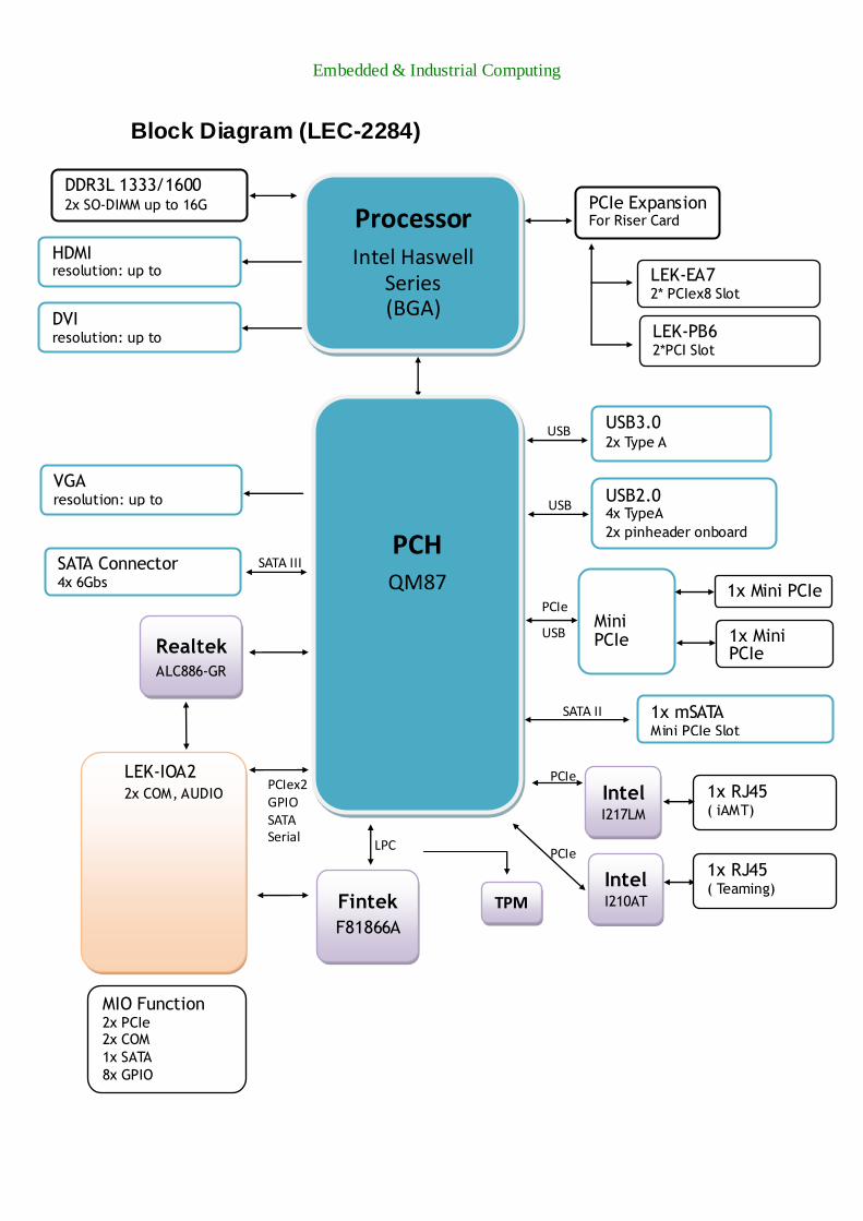
Block Diagram (LEC-2284)
1x mSATA Mini PCIe Slot
SATA II
PCIex2 GPIO SATA Serial
HDMI resolution: up to
4096x2304
Processor Intel Haswell
Series (BGA)
DDR3L 1333/1600 2x SO-DIMM up to 16G PCIe Expansion
For Riser Card
LEK-EA7 2* PCIex8 Slot
LEK-PB6 2*PCI Slot
PCH QM87
VGA resolution: up to
1920x1200
SATA Connector 4x 6Gbs
USB3.0 2x Type A
USB2.0 4x TypeA
2x pinheader onboard
SATA III
USB
USB
Mini PCIe
1x Mini PCIe
1x Mini PCIe with SIM Card
PCIe
USB Realtek
ALC886-GR
MIO Function 2x PCIe 2x COM
1x SATA
8x GPIO
Fintek
F81866A
LPC
LEK-IOA2
2x COM, AUDIO
PCIe
Intel I217LM
Intel I210AT
1x RJ45 ( iAMT)
1x RJ45 ( Teaming)
PCIe
DVI resolution: up to 2560x1600
TPM
Embedded & Industrial Computing
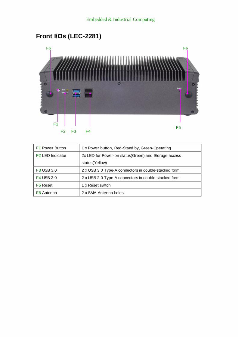
Front I/Os (LEC-2281)
F1 Power Button 1 x Power button, Red-Stand by, Green-Operating
F2 LED Indicator 2x LED for Power-on status(Green) and Storage access
status(Yellow)
F3 USB 3.0 2 x USB 3.0 Type-A connectors in double-stacked form
F4 USB 2.0 2 x USB 2.0 Type-A connectors in double-stacked form
F5 Reset 1 x Reset switch
F6 Antenna 2 x SMA Antenna holes
F1
F2 F3 F4 F5
F6 F6

Embedded & Industrial Computing
Rear I/Os (LEC-2281)
R1 Power Input 2-pin power input DC +9~+30VDC
R2 USB 2 x USB2.0 type A connectors
R3 LAN 2x 10/100/1000Mbps LAN ports
R4 Expansion 1x PCIe expansion slot; standard with x16 riser card
Option: 1x PCI expansion slot (included in package)
R5 DVI-D 1 x DVI-D display connector
R6 HDMI 1 x HDMI port
R7 VGA 1 x VGA display port
R8 COM 2 x DB9 COM ports with RS-232/422/485 signals
R9 Audio Mic-in, Line-out
R1 R2 R3
R4
R5 R6 R7
R8 R9

Embedded & Industrial Computing
Front I/Os (LEC-2284)
F1 Power Button 1 x Power button, Red-Stand by, Green-Operating
F2 LED Indicator 2x LED for Power-on status(Green) and Storage access
status(Yellow)
F3 USB 3.0 2 x USB 3.0 Type-A connectors in double-stacked form
F4 USB 2.0 2 x USB 2.0 Type-A connectors in double-stacked form
F5 Reset 1 x Reset switch
F6 Antenna 2 x SMA Antenna holes
F7 HDD/SSD trays 2 x Externally accessible SATA 2.5” HDD/SSD drive trays
F1
F2 F3
F4 F5 F6
F6
R7

Embedded & Industrial Computing
Rear I/Os (LEC-2284)
R1 Power Input 2-pin power input DC +9~+30VDC
R2 USB 2 x USB2.0 type A connectors
R3 LAN 2x 10/100/1000Mbps LAN ports
R4 Expansion 2x PCIe expansion slot; standard with x8 riser card
Option: 2x PCI expansion slot (included in package)
R5 DVI-D 1 x DVI-D display connector
R6 HDMI 1 x HDMI port
R7 VGA 1 x VGA display port
R8 COM 2 x DB9 COM ports with RS-232/422/485 signals
R9 Audio Mic-in, Line-out
R1 R2
R3
R4
R5 R6 R7
R8 R9
Embedded & Industrial Computing
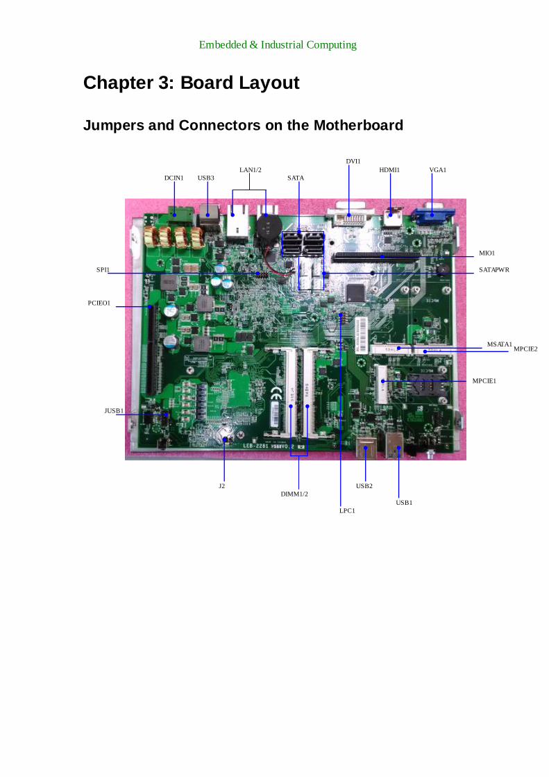
Chapter 3: Board Layout
Jumpers and Connectors on the Motherboard
DIMM1/2
DVI1
PCIEO1
HDMI1
VGA1
LAN1/2
USB1
USB3
USB2
DCIN1
MIO1
SPI1
JUSB1
LPC1
MPCIE1
MSATA1
SATA
SATAPWR
J2
MPCIE2

Embedded & Industrial Computing
Jumpers and Connectors on the Add-on Board
LEK-IOA2
Top Side
Rear Side
P12V1
J1

Embedded & Industrial Computing
Jumpers and Connectors on the Add-on Board
LEK-PB5
LEK-PB6
LEK-EA6
PCI
PCIE
PCI2
PCI1
Embedded & Industrial Computing
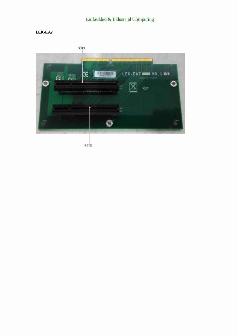
LEK-EA7
PCIE1
PCIE2

Embedded & Industrial Computing
Jumpers and Connectors List
Labels Descriptions Remarks
VGA1 VGA display interface
DVI1 DVI-D digital visual interface
HDMI1 High definition multimedia interface
LAN1/2 2 x RJ-45 LAN connectors
USB1 USB 3.0 double stacked ports
USB2/3 USB 2.0 double stacked ports
JUSB1 Internal USB pin header
MPCIE1 Mini-PCIe socket with SIM card reader
MPCIE2 Mini-PCIe socket
MSATA1 mSATA socket
MIO1 Multiple I/O interface for add-on cards
PCIEO1 PCIe multiple I/O interface for riser
card
DCIN1 2-pin DC power input 9-30V
CMOS1 Clear CMOS jumper
SPI1 SPI for debug use
LPC1 Low-pin-count for debug use
J2 PCIe configuration jumper

Embedded & Industrial Computing
Jumper Setting and Connector Pin-out
VGA Connector (VGA1): DB-15 VGA display connector
Digital Visual Interface Port (DVI1): a DVI-D display connector
HDMI (High Definition Multimedia Interface) Ports (HDMI1): HDMI display port
Pin No. Description Pin No. Description
1 DATA2+ 2 GND
3 DATA2- 4 DATA1+
5 GND 6 DATA1-
7 DATA0+ 8 GND
9 DATA0- 10 CLK+
11 GND 12 CLK-
13 N.C 14 N.C
15 DDC CLK 16 DDC DAT
17 GND 18 HDMI_VCC
19 HPD
Pin No. Description Pin No. Description Pin No. Description
1 DATA2- 9 DATA1- 17 DATA0-
2 DATA2+ 10 DATA1+ 18 DATA0+
3 GND 11 GND 19 GND
4 DATA4- 12 DATA3- 20 DATA5-
5 DATA4+ 13 DATA3+ 21 DATA5+
6 DDC_CLK 14 VCC 22 GND
7 DDC_DAT 15 GND 23 CLK+
8 N.C 16 HP_DET 24 CLK-
Pin No. Description Pin No. Description Pin No. Description
1 CRT-R 6 GND 11 N.C
2 CRT-G 7 GND 12 V_SDAT
3 CRT-B 8 GND 13 HSYNC
4 N.C 9 VCC 14 VSYNC
5 GND 10 GND 15 V_SCLK
VGA1
5
1

Embedded & Industrial Computing
Ethernet (LAN1/2): 2 x RJ-45 LAN connectors
USB 3.0 Connectors (USB1): USB3.0 ports in double-stacked form
PIN NO 9 8 7 6 5
DESCRIPTION USB1_TX+ USB1_TX- GND USB1_RX+ USB1_RX-
PIN NO 1 2 3 4
DESCRIPTION USB_VCC1 USB1_D- USB1_D+ GND
USB 2.0 Connectors (USB2/3): USB 2.0 ports in double stacked form
Pin No. Description
1 TXD+ MD0+
2 TXD- MD0-
3 RXD+ MD1+
4 T45 MD2+
5 T45 MD2-
6 RXD- MD1-
7 T78 MD3+
8 T78 MD3-
9 10-/100-/1000+
10 10+/100+/1000-
11 NC
12 NC
13 Active LED-(yellow)
14 Active LED+
PIN NO. DESCRIPTION
1 USB_VCC1
2 -USB
3 +USB
4 GND
0 USB_VCC2
6 -USB
7 +USB
8 GND
USBB2/3
5 8
4 1

Embedded & Industrial Computing
Internal USB Pin Header (JUSB1)
Mini-PCIe Expansion (MPCIE1): mini-PCIe expansion socket with SIM Card reader
PIN NO. DESCRIPTION PIN NO DESCRIPTION
1 USB_VCC 2 GND
3 KEY 4 +USB
5 -USB 6 -USB
7 +USB 8 KEY
9 GND 10 USB_VCC
Pin NO DESCRIPTION Pin NO DESCRIPTION
1 WAKE# 2 +3.3V
3 RSVD 4 GND
5 RSVD 6 +1.5V
7 CLKREQ# 8 UIM_PWR
9 GND 10 UIM_DATA
11 REFCLK- 12 UIM_CLK
13 REFCLK+ 14 UIM_RESET
15 GND 16 UIM_VPP
KEY
17 RSVD 18 GND
19 RSVD 20 W_DISABLE#
21 GND 22 PERST#
23 PERn0 24 +3.3V
25 PERp0 26 GND
27 GND 28 +1.5V
29 GND 30 SMB_CLK
31 PETn0 32 SMB_DATA
33 PETp0 34 GND
35 GND 36 USB_D+
37 GND 38 USB_D-
39 +3.3V 40 GND
41 +3.3V 42 LED_WWAN#
43 GND 44 LED_WLAN#
45 RSVD 46 LED_WPAN#
47 RSVD 48 +1.5V
49 RSVD 50 GND
51 RSVD 52 +3.3V
2
USB1 9
1
0
1

Embedded & Industrial Computing
mSATA (MSATA1): mSATA socket for storage
Pin NO DESCRIPTION Pin NO DESCRIPTION
1 N.C 2 +3.3V
3 N.C 4 GND
5 N.C 6 N.C
7 N.C 8 N.C
9 GND 10 N.C
11 N.C 12 N.C
13 N.C 14 N.C
15 GND 16 N.C
KEY
17 N.C 18 GND
19 N.C 20 N.C
21 GND 22 N.C
23 SATA_RXp 24 +3.3V
25 SATA_RXn 26 GND
27 GND 28 N.C
29 GND 30 N.C
31 SATA_TXn 32 N.C
33 SATA_TXp 34 GND
35 GND 36 N.C
37 GND 38 N.C
39 +3.3V 40 GND
41 +3.3V 42 N.C
43 GND 44 N.C
45 N.C 46 N.C
47 N.C 48 N.C
49 N.C 50 GND
51 N.C 52 +3.3V
Embedded & Industrial Computing
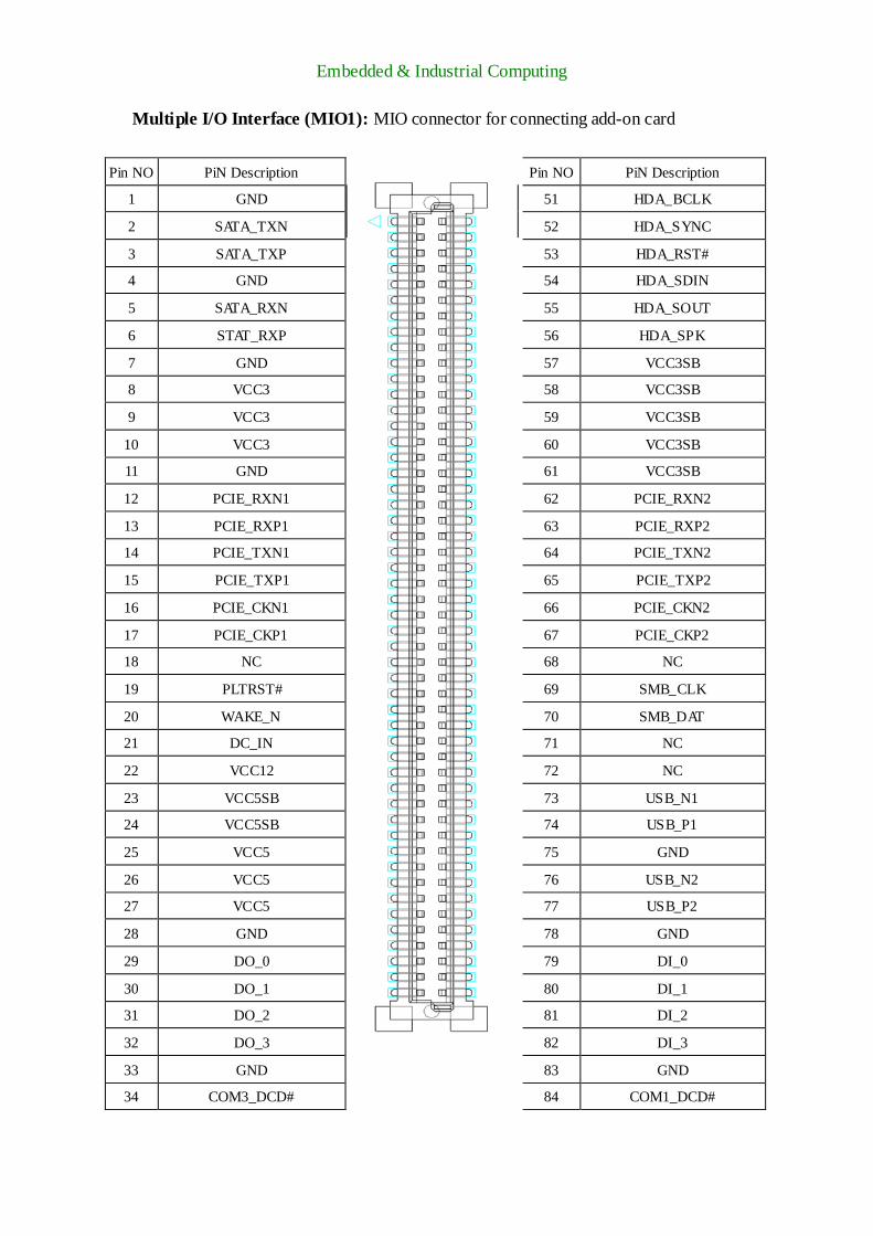
Multiple I/O Interface (MIO1): MIO connector for connecting add-on card
Pin NO PiN Description
Pin NO PiN Description
1 GND 51 HDA_BCLK
2 SATA_TXN 52 HDA_SYNC
3 SATA_TXP 53 HDA_RST#
4 GND 54 HDA_SDIN
5 SATA_RXN 55 HDA_SOUT
6 STAT_RXP 56 HDA_SPK
7 GND 57 VCC3SB
8 VCC3 58 VCC3SB
9 VCC3 59 VCC3SB
10 VCC3 60 VCC3SB
11 GND 61 VCC3SB
12 PCIE_RXN1 62 PCIE_RXN2
13 PCIE_RXP1 63 PCIE_RXP2
14 PCIE_TXN1 64 PCIE_TXN2
15 PCIE_TXP1 65 PCIE_TXP2
16 PCIE_CKN1 66 PCIE_CKN2
17 PCIE_CKP1 67 PCIE_CKP2
18 NC 68 NC
19 PLTRST# 69 SMB_CLK
20 WAKE_N 70 SMB_DAT
21 DC_IN 71 NC
22 VCC12 72 NC
23 VCC5SB 73 USB_N1
24 VCC5SB 74 USB_P1
25 VCC5 75 GND
26 VCC5 76 USB_N2
27 VCC5 77 USB_P2
28 GND 78 GND
29 DO_0 79 DI_0
30 DO_1 80 DI_1
31 DO_2 81 DI_2
32 DO_3 82 DI_3
33 GND 83 GND
34 COM3_DCD# 84 COM1_DCD#

Embedded & Industrial Computing
35 COM3_RI# 85 COM1_RI#
36 COM3_CTS# 86 COM1_CTS#
37 COM3_DTR# 87 COM1_DTR#
38 COM3_RTS# 88 COM1_RTS#
39 COM3_DSR# 89 COM1_DSR#
40 COM3_SOUT 90 COM1_SOUT
41 COM3_SIN 91 COM1_SIN
42 GND 92 GND
43 COM4_DCD# 93 COM2_DCD#
44 COM4_RI# 94 COM2_RI#
45 COM4_CTS# 95 COM2_CTS#
46 COM4_DTR# 96 COM2_DTR#
47 COM4_RTS# 97 COM2_RTS#
48 COM4_DSR# 98 COM2_DSR#
49 COM4_SOUT 99 COM2_SOUT
50 COM4_SIN 100 COM2_SIN

Embedded & Industrial Computing
PCIe Expansion Socket (PCIEO1): PCIe interface connector for riser card
Pin NO Description
Pin NO Description
1 VCC3SB 2 VCC5SB
3 VCC3SB 4 VCC5SB
5 NC 6 NC
7 VCC3P3 8 V1P5
9 VCC3P3 10 NC
11 VCC3P3 12 VCC5
13 VCC3P3 14 VCC5
15 VCC3P3 16 VCC5
17 VCC3P3 18 VCC5
19 NC 20 VCC5
21 GND 22 VCC5
23 NC 24 NC
25 +12 26 GND
27 +12 28 GND
29 +12 30 CLKRQ1
31 +12 32 CLKRQ2
33 NC 34 GND
35 PLTRST# 36 SMB_CLK
37 PCIE_WAKE# 38 SMB_DAT
39 GND 40 GND
41 PCIE_RXN2 42 PCIE_CKN2
43 PCIE_RXP2 44 PCIE_CKP2
45 GND 46 GND
47 PCIE_RXP1 48 PCIE_TXN2
49 PCIE_RXN1 50 PCIE_TXP2
51 GND 52 GND
53 PCIE_CKP1 54 PCIE_TXN1
55 PCIE_CKN1 56 PCIE_TXP1
57 GND 58 GND
59 PEGA_CLKN 60 PEGB_CLKN
61 PEGA_CLKP 62 PEGB_CLKP
63 GND 64 GND
KEY KEY
65 GND 66 GND
67 PEG_RXN15 68 PEG_TXN15
69 PEG_RXP15 70 PEG_TXP15
71 GND 72 GND
73 PEG_RXN14 74 PEG_TXN14
75 PEG_RXP14 76 PEG_TXP14
77 GND 78 GND
79 PEG_RXN13 80 PEG_TXN13
81 PEG_RXP13 82 PEG_TXP13
83 GND 84 GND
85 PEG_RXN12 86 PEG_TXN12
87 PEG_RXP12 88 PEG_TXP12

Embedded & Industrial Computing
89 GND 90 GND
91 PEG_RXN11 92 PEG_TXN11
93 PEG_RXP11 94 PEG_TXP11
95 GND 96 GND
97 PEG_RXN10 98 PEG_TXN10
99 PEG_RXP10 100 PEG_TXP10
101 GND 102 GND
103 PEG_RXN9 104 PEG_TXN9
105 PEG_RXP9 106 PEG_TXP9
107 GND 108 GND
109 PEG_RXN8 110 PEG_TXN8
111 PEG_RXP8 112 PEG_TXP8
113 GND 114 GND
115 PEG_RXN7 116 PEG_TXN7
117 PEG_RXP7 118 PEG_TXP7
119 GND 120 GND
121 PEG_RXN6 122 PEG_TXN6
123 PEG_RXP6 124 PEG_TXP6
125 GND 126 GND
127 PEG_RXN5 128 PEG_TXN5
129 PEG_RXP5 130 PEG_TXP5
131 GND 132 GND
133 PEG_RXN4 134 PEG_TXN4
135 PEG_RXP4 136 PEG_TXP4
137 GND 138 GND
139 PEG_RXN3 140 PEG_TXN3
141 PEG_RXP3 142 PEG_TXP3
143 GND 144 GND
145 PEG_RXN2 146 PEG_TXN2
147 PEG_RXP2 148 PEG_TXP2
149 GND 150 GND
151 PEG_RXN1 152 PEG_TXN1
153 PEG_RXP1 154 PEG_TXP1
155 GND 156 GND
157 PEG_RXN0 158 PEG_TXN0
159 PEG_RXP0 160 PEG_TXP0

Embedded & Industrial Computing
DC Power input (DCIN1): 2-pin Phoenix connector for power input (9 to 30V)
CMOS1:Clear CMOS jumper
SPI Interface(SPI1): SPI pin header for debug use
PIN NO. DESCRIPTION PIN NO. DESCRIPTION
1 SPI_HOLD 2 N.C
3 SPI_CS# 4 SPI_VCC
5 SPI_MO 6 N.C
7 N.C 8 SPI_CLK
9 GND 10 SPI_MI
PIN NO. DESCRIPTION
1 DC_IN (GND)
2 DC_IN (9~30V)
Description Short pin
Normal (Default) 1-2
Clear CMOS 2-3
Clear CMOS
Normal(Def)
CMOS1
1
2
3
CMOS1
1
2
3
1
2
3
2
SPI1 9
10
1
Embedded & Industrial Computing
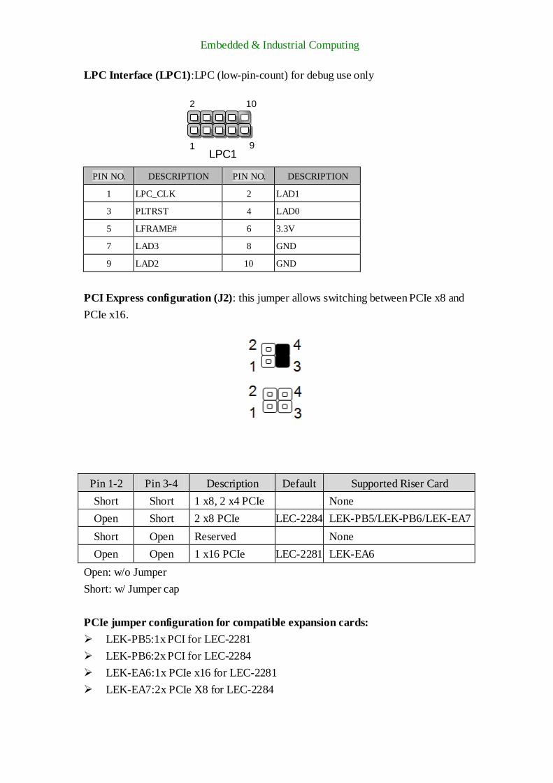
LPC Interface (LPC1):LPC (low-pin-count) for debug use only
PIN NO. DESCRIPTION PIN NO. DESCRIPTION
1 LPC_CLK 2 LAD1
3 PLTRST 4 LAD0
5 LFRAME# 6 3.3V
7 LAD3 8 GND
9 LAD2 10 GND
PCI Express configuration (J2): this jumper allows switching between PCIe x8 and
PCIe x16.
Pin 1-2 Pin 3-4 Description Default Supported Riser Card
Short Short 1 x8, 2 x4 PCIe None
Open Short 2 x8 PCIe LEC-2284 LEK-PB5/LEK-PB6/LEK-EA7
Short Open Reserved None
Open Open 1 x16 PCIe LEC-2281 LEK-EA6
Open: w/o Jumper
Short: w/ Jumper cap
PCIe jumper configuration for compatible expansion cards:
LEK-PB5:1x PCI for LEC-2281
LEK-PB6:2x PCI for LEC-2284
LEK-EA6:1x PCIe x16 for LEC-2281
LEK-EA7:2x PCIe X8 for LEC-2284
2
LPC1 9
10
1

Embedded & Industrial Computing
Serial Ports (COM1-2): 2 x D-sub9 RS-232/422/485 serial ports
PIN NO. DESCRIPTION
RS-232 RS-422 RS-485
1 DCD TXD- DATA-
2 RXD TXD+ DATA+
3 TXD RXD+
4 DTR RXD-
5 GND
6 DSR
7 RTS
8 CTS
9 RI
COM Protocol Setting (SCT1/SCT2): jumpers select for COM1 protocol setting.
The diagram is for instruction purpose about the pins to short.

Embedded & Industrial Computing
COM Protocol Setting (SCT3/SCT4): jumpers select for COM2 protocol setting.
The diagram is for instruction purpose about the pins to short.
SCT1 SCT2
RS-232 (Default)
1-5
2-6
3-7
4-8
1-2
RS-422
5-9
6-10
7-11
8-12
3-4
RS-485
5-9
6-10
7-11
8-12
5-6
SCT1 SCT2
RS-232 (Default)
1-5
2-6
3-7
4-8
1-2
RS-422
5-9
6-10
7-11
8-12
3-4
RS-485
5-9
6-10
7-11
8-12
5-6
Switch Protocol
Switch Protocol

Embedded & Industrial Computing
COM1-2 Pin9 Setting (JP1/JP2): the JP1/2 jumper setting is designed to configure
the Pin9 (Ring Indicator) functionality for COM1/COM2.
JP1 JP2
Pin Signal Pin Signal
1-2 VCC5 1-2 VCC5
3-4 VCC12 3-4 VCC12
5-6 SPI_RI 5-6 SPI_RI
Embedded & Industrial Computing
Chapter 4: Hardware Setup
Preparing the Hardware Installation
To access some components and perform certain service procedures, you must perform the
following procedures first.
WARNING:
To reduce the risk of personal injury, electric shock, or damage to the equipment, please
remove all power sources.
Please wear ESD protected gloves before conducting the following steps.
Do NOT pile items on the system.
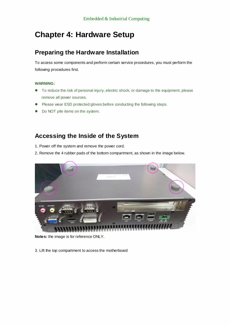
Accessing the Inside of the System
1. Power off the system and remove the power cord.
2. Remove the 4 rubber pads of the bottom compartment, as shown in the image below.
Notes: the image is for reference ONLY.
3. Lift the top compartment to access the motherboard

Embedded & Industrial Computing
Installing the System Memory
The motherboard supports DDR3L memory that features data transfer rates of 1333/1600
MHz to meet the bandwidth requirements of current operating system and Internet applications.
It comes with two DDR3L Small Outline Dual In-line Memory Module (SO-DIMM) socket.
1. Align the memory module’s key with the SO-DIMM socket’s key.
2. Insert the SO-DIMM.
Note:
1. SO-DIMMs installed should meet the required speed which is 1333/1600 MHz. Do not install
SODIMM supporting different frequencies.
2. Each SO-DIMM socket on this motherboard supports up to 8GB.

Embedded & Industrial Computing
Installing a mSATA or Mini-PCIe module
The system provides a mSATA socket and two mini-PCIe slots for expansions. Please follow
the steps below for installations.
1. Locate the mSATA or the mini-PCIe socket.
2. Align the mechanical notches between the module and the socket.
3. Insert the module into the socket.
4. Secure the installed module with two screws.
Installing a Disk Drive for LEC-2281
The system can accommodate two 2.5” SATA disk drives. Please follow the steps below.
1. Locate the SATA drive tray on the inner side of the bottom compartment. You have to
remove the 4 rubber pads on the bottom of the system.
2. Apply 4 screws for each disk drive. There are 8 screw holes in total. When placing a SATA
disk drive, make sure the SATA connector face the direction as shown in the arrow of direction
below.
mSATA
Mini-PCIe
with SIM
Mini-PCIe

Embedded & Industrial Computing
3. Prepare the supplied SATA cable.
To the SATA drive
To the SATA 7-pin connector
on the motherboard
To the SATA 4-pin power
connector on the motherboard

Embedded & Industrial Computing
Installing a Disk Drive for LEC-2284
The system provides two 2.5” SATA disk drives that are externally accessible. Please follow
the steps below for disk installation.
1. Unscrew the captive screw at the door of the drive bay.
2. Hold onto the captive screw and gently pull it outwards.
3. When the tray is removed from the drive bay, install a SATA 2.5” HDD/SSD into the tray and
apply 4 screws to fix it.

Embedded & Industrial Computing
Connecting Power
Connect the system to a compliant DC power source. The power source comes from the
AC/DC Adapter through a Phoenix contact. This power socket is purposely designed to guard
against fault in power contact so that the reverse of the electrical polarity will not damage the
system.
Embedded & Industrial Computing
Appendix1: Programming Watchdog Timer
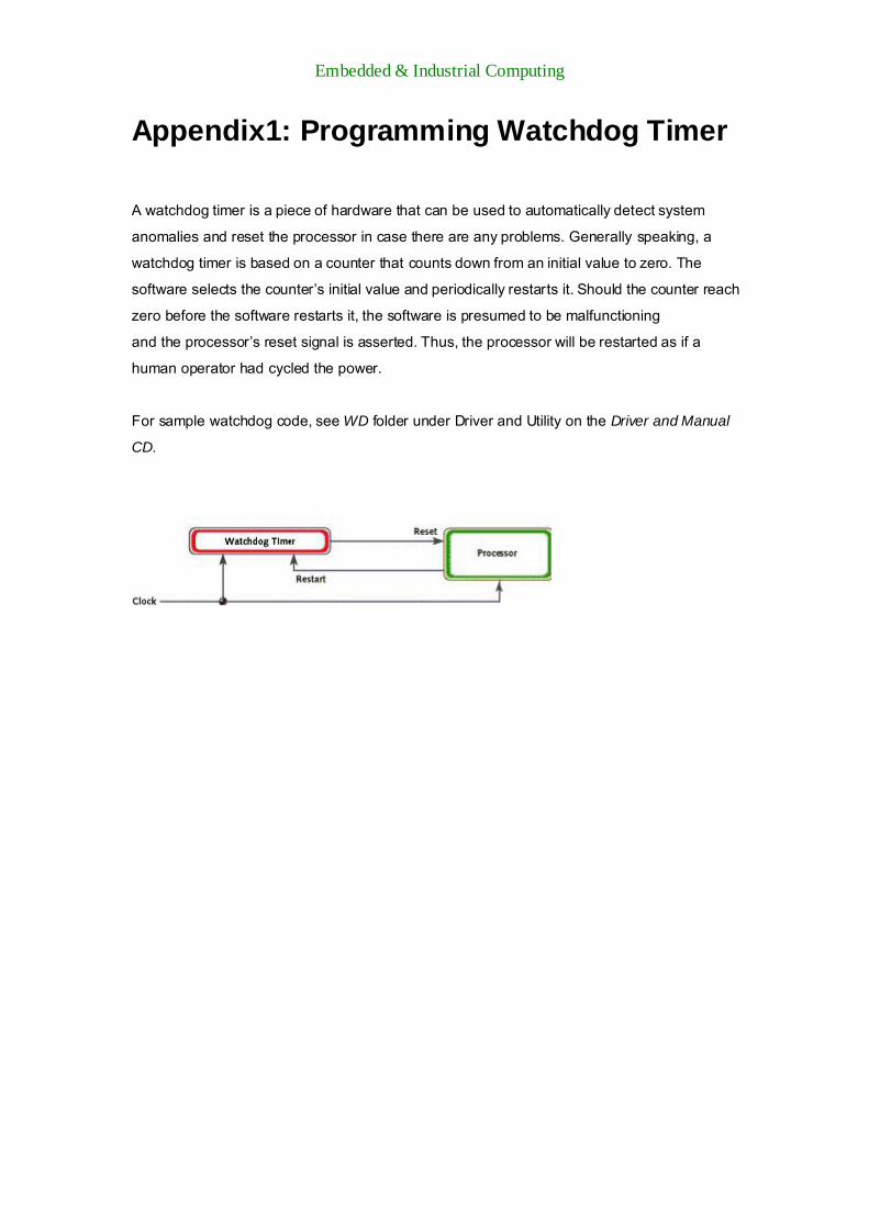
A watchdog timer is a piece of hardware that can be used to automatically detect system
anomalies and reset the processor in case there are any problems. Generally speaking, a
watchdog timer is based on a counter that counts down from an initial value to zero. The
software selects the counter’s initial value and periodically restarts it. Should the counter reach
zero before the software restarts it, the software is presumed to be malfunctioning
and the processor’s reset signal is asserted. Thus, the processor will be restarted as if a
human operator had cycled the power.
For sample watchdog code, see WD folder under Driver and Utility on the Driver and Manual
CD.