lect-14 · basic operation of axial compressors • turbines on the other hand operate under...
TRANSCRIPT
1
Lect-14
Prof. Bhaskar Roy, Prof. A M Pradeep, Department of Aerospace, IIT Bombay2
Lect-14
In this lecture...
• Axial flow compressors– Basic operation of axial compressors– Velocity triangles– Work and compression– Design parameters
• Flow coefficient• Loading coefficient• Degree of reaction• Diffusion factor
Prof. Bhaskar Roy, Prof. A M Pradeep, Department of Aerospace, IIT Bombay3
Lect-14
Basic operation of axial compressors• Axial flow compressors usually consists of a
series of stages.• Each stage comprises of a row of rotor
blades followed by a row of stator blades.• The working fluid is initially accelerated by
the rotor blades and then decelerated in the stator passages.
• In the stator, the kinetic energy transferred in the rotor is converted to static pressure.
• This process is repeated in several stages to yield the necessary overall pressure ratio.
Prof. Bhaskar Roy, Prof. A M Pradeep, Department of Aerospace, IIT Bombay4
Lect-14
Basic operation of axial compressors• The compression process consists of a series of
diffusions.• This occurs both in the rotor as well as the
stator. • Due to motion of the rotor blades two distinct
velocity components: absolute and relative velocities in the rotor.
• The absolute velocity of the fluid is increased in the rotor, whereas the relative velocity is decreased, leading to diffusion.
• Per stage pressure ratio is limited because a compressor operates in an adverse pressure gradient environment.
Prof. Bhaskar Roy, Prof. A M Pradeep, Department of Aerospace, IIT Bombay5
Lect-14
Basic operation of axial compressors
• Turbines on the other hand operate under favourable pressure gradients.
• Several stages of an axial compressor can be driven by a single turbine stage.
• Careful design of the compressor blading is essential to minimize losses as well as to ensure stable operation.
• Some compressors also have inlet Guide Vanes (IGV) that permit the flow entering the first stage to vary under off-design conditions.
Prof. Bhaskar Roy, Prof. A M Pradeep, Department of Aerospace, IIT Bombay6
Lect-14
Velocity triangles• Elementary analysis of axial compressors begins
with velocity triangles.• The analysis will be carried out at the mean height
of the blade, where the peripheral velocity or the blade speed is, U.
• The absolute component of velocity will be denoted by, C and the relative component by, V.
• The axial velocity (absolute) will be denoted by Caand the tangential components will be denoted by subscript w (for eg, Cw or Vw)
• α denotes the angle between the absolute velocity with the axial direction and β the corresponding angle for the relative velocity.
Prof. Bhaskar Roy, Prof. A M Pradeep, Department of Aerospace, IIT Bombay7
Lect-14
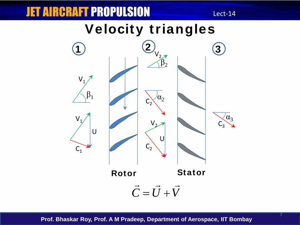
Velocity triangles
U
C1C2
C3V1 V2
V2
C2
Rotor Stator
1 2 3
β1
β2
α2
α3
U
V1
VUC
+=
Prof. Bhaskar Roy, Prof. A M Pradeep, Department of Aerospace, IIT Bombay8
Lect-14
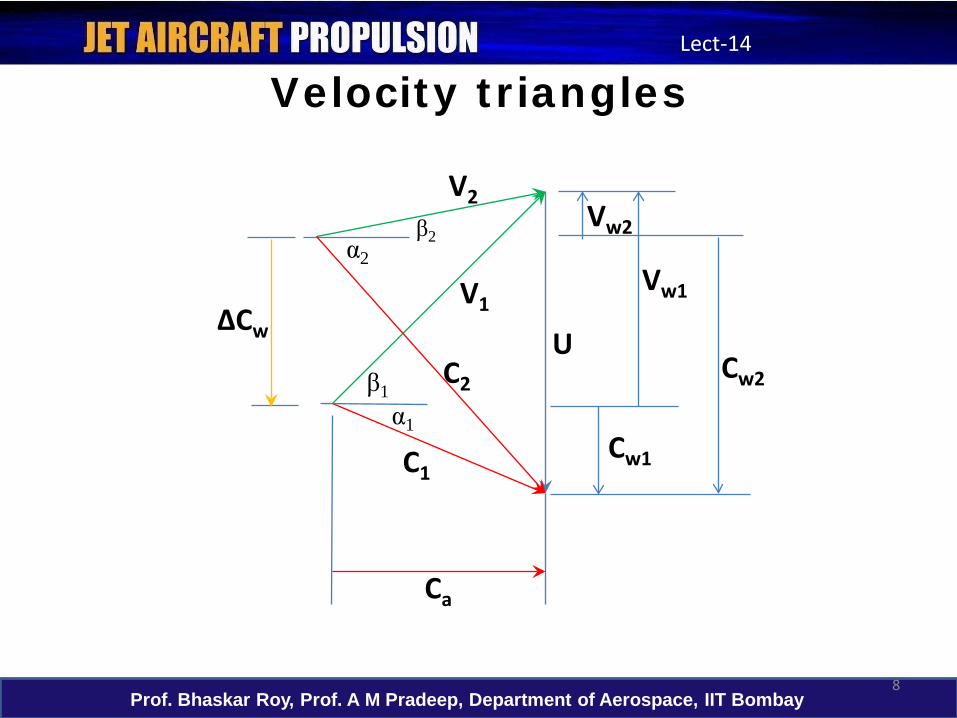
Velocity triangles
U
C1
C2
Ca
V1
V2
β1
β2α2
α1
ΔCw
Vw2
Vw1
Cw2
Cw1
Prof. Bhaskar Roy, Prof. A M Pradeep, Department of Aerospace, IIT Bombay9
Lect-14
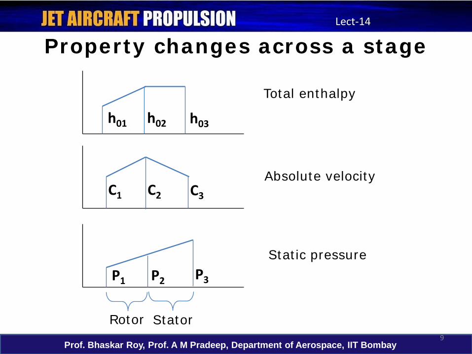
Property changes across a stage
Total enthalpy
Absolute velocity
Static pressure
C1 C2 C3
h01 h02 h03
P1 P2 P3
Rotor Stator
Prof. Bhaskar Roy, Prof. A M Pradeep, Department of Aerospace, IIT Bombay10
Lect-14
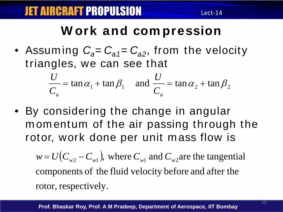
Work and compression• Assuming Ca=Ca1=Ca2, from the velocity
triangles, we can see that
• By considering the change in angular momentum of the air passing through the rotor, work done per unit mass flow is
2211 tantanandtantan βαβα +=+=aa C
UCU
( )
ly.respective rotor, after the and before velocity fluid theof components
l tangentia theare and where, 2112 wwww CCCCUw −=
Prof. Bhaskar Roy, Prof. A M Pradeep, Department of Aerospace, IIT Bombay11
Lect-14
Work and compression
w
a
a
CUwUCw
UCw
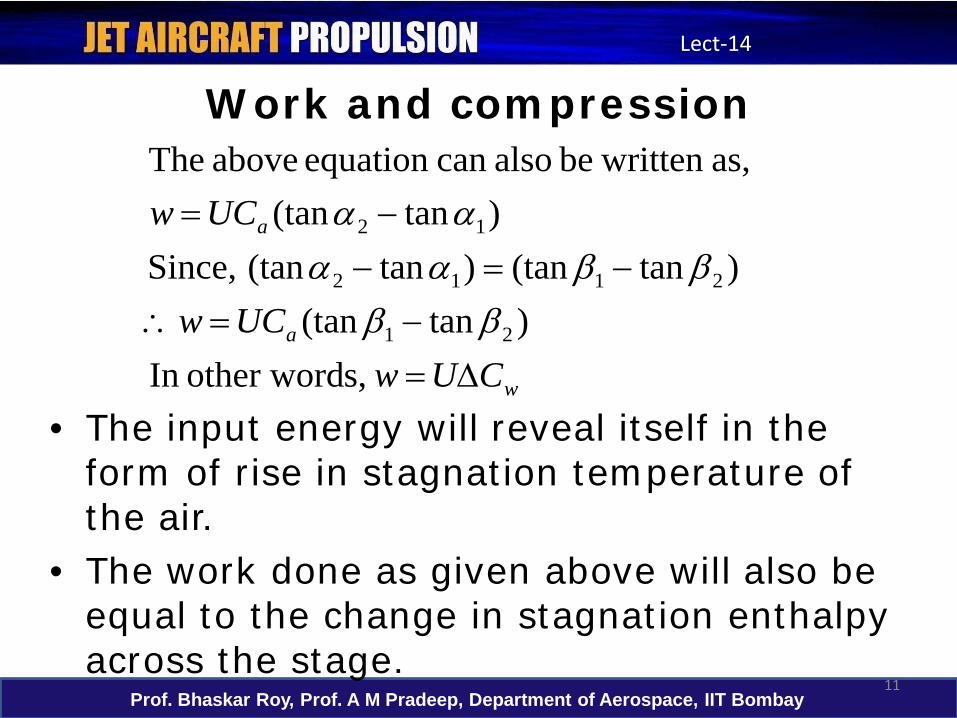
∆=−=∴
−=−−=
s,other wordIn )tan(tan
)tan(tan)tan(tan,Since)tan(tan
as, written be alsocan equation above The
21
2112
12
ββββαα
αα
• The input energy will reveal itself in the form of rise in stagnation temperature of the air.
• The work done as given above will also be equal to the change in stagnation enthalpy across the stage.
Prof. Bhaskar Roy, Prof. A M Pradeep, Department of Aerospace, IIT Bombay12
Lect-14
Work and compression
01
0st
01
03
0103
0103st
st
0203
0101
00102
0102
1
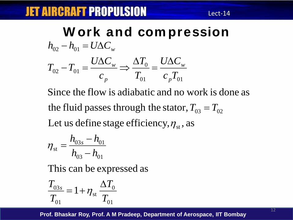
as expressed becan This
as ,,efficiency stage define usLet stator, he through tpasses fluid the
as done is work no and adiabatic is flow theSince
TT
TT
hhhh
TT
TcCU
TT
cCUTT
CUhh
s
s
p
w
p
w
w
∆+=
−−
=
=
∆=
∆⇒
∆=−
∆=−
η
η
η
Prof. Bhaskar Roy, Prof. A M Pradeep, Department of Aerospace, IIT Bombay13
Lect-14
Work and compression
( )
( )1/
0101
03
1/
01
0
01
03
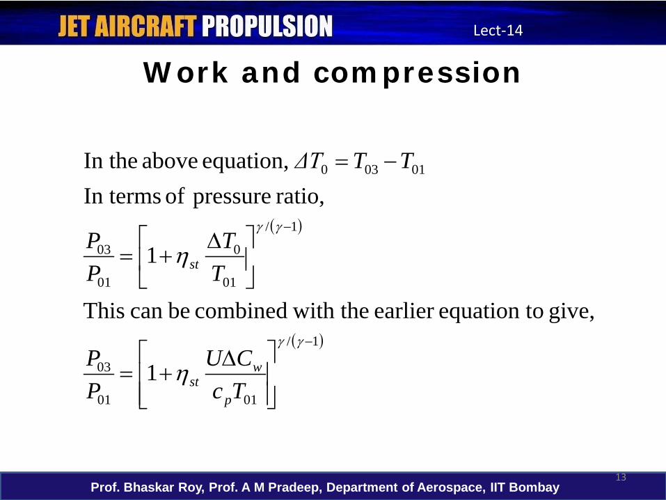
01030
1
give, oequation tearlier with thecombined becan This
1
ratio, pressure of In terms equation, above In the
−
−
∆+=
∆+=
−=
γγ
γγ
η
η
TcCU
PP
TT
PP
TTΔT
p
wst
st
Prof. Bhaskar Roy, Prof. A M Pradeep, Department of Aerospace, IIT Bombay14
Lect-14
Work and compression• From the above equation that relates the
per stage temperature rise to the pressure ratio, it can be seen that to obtain a high temperature ratio for a given overall pressure ratio (for minimizing number of stages),– High blade speed: limited by blades stresses– High axial velocity, high fluid deflection
(β1-β2): Aerodynamic considerations and adverse pressure gradients limit the above.
Prof. Bhaskar Roy, Prof. A M Pradeep, Department of Aerospace, IIT Bombay15
Lect-14
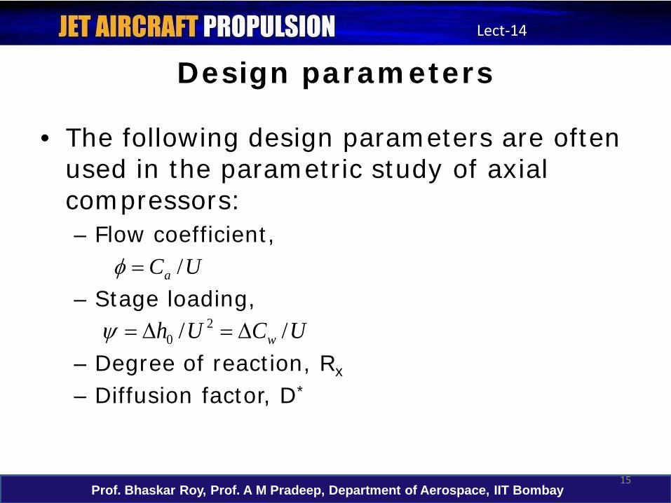
Design parameters
• The following design parameters are often used in the parametric study of axial compressors:– Flow coefficient,
– Stage loading,
– Degree of reaction, Rx
– Diffusion factor, D*
UCa /=φ
UCUh w // 20 ∆=∆=ψ
Prof. Bhaskar Roy, Prof. A M Pradeep, Department of Aerospace, IIT Bombay16
Lect-14
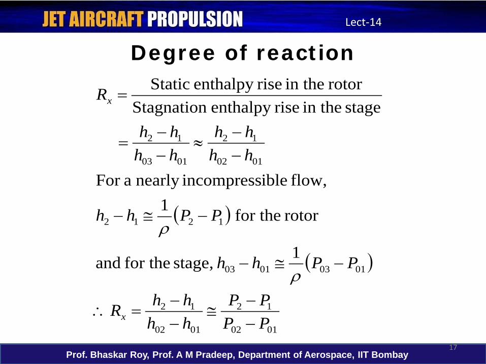
Degree of reaction
• Diffusion takes place in both rotor and the stator.
• Static pressure rises in the rotor as well as the stator.
• Degree of reaction provides a measure of the extent to which the rotor contributes to the overall pressure rise in the stage.
Prof. Bhaskar Roy, Prof. A M Pradeep, Department of Aerospace, IIT Bombay17
Lect-14
Degree of reaction
( )
( )
0102
12
0102
12
01030103
1212
0102
12
0103
12
1 stage, for the and
rotor for the1 flow, ibleincompressnearly aFor
stage in the riseenthalpy Stagnationrotor in the riseenthalpy Static
PPPP
hhhhR
PPhh
PPhh
hhhh
hhhh
R
x
x
−−
≅−−
=∴
−≅−
−≅−
−−
≈−−
=
=
ρ
ρ
Prof. Bhaskar Roy, Prof. A M Pradeep, Department of Aerospace, IIT Bombay18
Lect-14
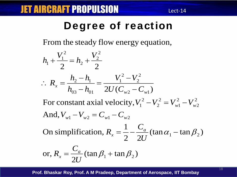
Degree of reaction
)tan(tan2
or,
)tan(tan22
1 tion,simplificaOn
And, velocity,axialconstant For
)(2
22
equation,energy flowsteady theFrom
21
21
2121
22
21
22
21
12
22
21
0103
12
22
2
21
1
ββ
βα
+=
−−=
−=−−=−
−−
=−−
=∴
+=+
UCR
UCR
CCVVVVVV
CCUVV
hhhhR
VhVh
ax
ax
wwww
ww
wwx
Prof. Bhaskar Roy, Prof. A M Pradeep, Department of Aerospace, IIT Bombay19
Lect-14
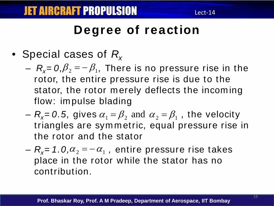
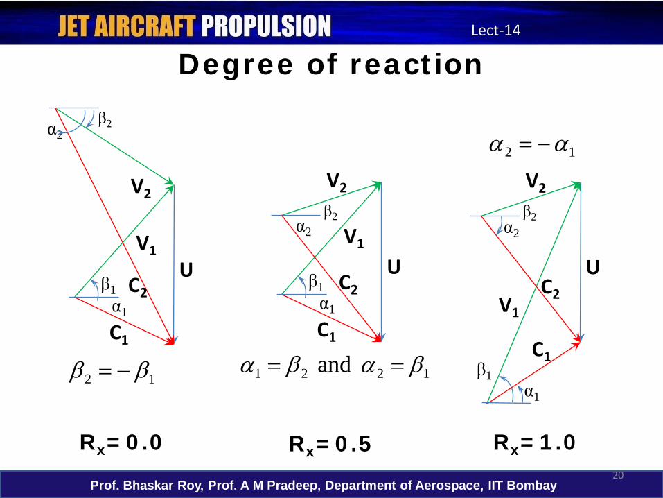
Degree of reaction
• Special cases of Rx– Rx=0, , There is no pressure rise in the
rotor, the entire pressure rise is due to the stator, the rotor merely deflects the incoming flow: impulse blading
– Rx=0.5, gives , the velocity triangles are symmetric, equal pressure rise in the rotor and the stator
– Rx=1.0, , entire pressure rise takes place in the rotor while the stator has no contribution.
1221 and βαβα ==
12 ββ −=
12 αα −=
Prof. Bhaskar Roy, Prof. A M Pradeep, Department of Aerospace, IIT Bombay20
Lect-14
Degree of reaction
U
C1
C2
V1
V2
β1
β2α2
α1
U
C1
C2
V1
V2
β1
β2α2
α1
U
C1
C2V1
V2
β1
β2α2
α1
1221 and βαβα ==12 ββ −=
12 αα −=
Rx=0.0 Rx=0.5 Rx=1.0
Prof. Bhaskar Roy, Prof. A M Pradeep, Department of Aerospace, IIT Bombay21
Lect-14
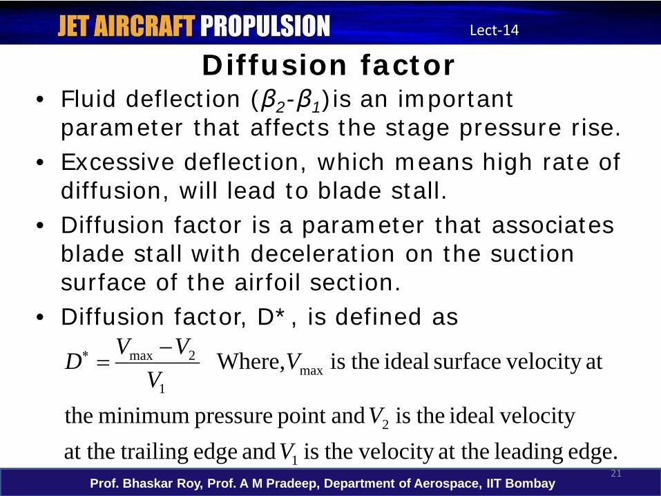
Diffusion factor• Fluid deflection (β2-β1)is an important
parameter that affects the stage pressure rise.• Excessive deflection, which means high rate of
diffusion, will lead to blade stall.• Diffusion factor is a parameter that associates
blade stall with deceleration on the suction surface of the airfoil section.
• Diffusion factor, D*, is defined as
edge. leading at the velocity theis and edge trailingat the velocity ideal theis andpoint pressure minimum the
at velocity surface ideal theis Where,
1
2
max1
2max
VV
VV
VVD −=∗
Prof. Bhaskar Roy, Prof. A M Pradeep, Department of Aerospace, IIT Bombay22
Lect-14
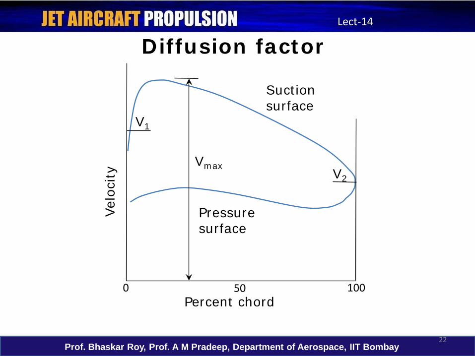
Diffusion factor
0 50 100
V2
V1
Vmax
Suction surface
Pressure surface
Velo
city
Percent chord
Prof. Bhaskar Roy, Prof. A M Pradeep, Department of Aerospace, IIT Bombay23
Lect-14
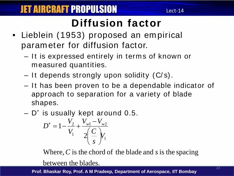
Diffusion factor• Lieblein (1953) proposed an empirical
parameter for diffusion factor.– It is expressed entirely in terms of known or
measured quantities.– It depends strongly upon solidity (C/s).– It has been proven to be a dependable indicator of
approach to separation for a variety of blade shapes.
– D* is usually kept around 0.5.
blades. ebetween thspacing theis and blade theof chord theis Where,
21
1
21
1
2
sC
VsC
VVVVD ww
−
+−=∗
Prof. Bhaskar Roy, Prof. A M Pradeep, Department of Aerospace, IIT Bombay24
Lect-14
In this lecture...• Axial flow compressors
– Basic operation of axial compressors– Velocity triangles– Work and compression– Design parameters
• Flow coefficient• Loading coefficient• Degree of reaction• Diffusion factor
Prof. Bhaskar Roy, Prof. A M Pradeep, Department of Aerospace, IIT Bombay25
Lect-14
In the next lecture...
• Cascade analysis– Cascade nomenclature– Loss and blade performance estimation