lecture 10: synchronous sequential logicwebpages.eng.wayne.edu/.../lecturenotes/lecture10.pdf ·...
TRANSCRIPT

Lecture 10: Synchronous Sequential Logic
Syed M. Mahmud, Ph.DECE Department
Wayne State University
Original Source: Aby K George, ECE Department, Wayne State University

Contents
• Introduction
• Sequential Circuits
• Storage Elements: Latches
• Storage Elements: Flip-Flops
• Analysis of Clocked Sequential Circuits
Chapter 5 ECE 2610 – Digital Logic 1 2

Introduction
• Storing information
• Memory
• Operation and Control of these devices
• Their use in the circuits
Chapter 5 ECE 2610 – Digital Logic 1 3

Sequential Circuits
• Combinational circuit with memory element in the feedback path.
• Storage elements can store binary information.
• A sequential circuit is specified by a time sequence of inputs, outputs, and internal states.
Chapter 5 ECE 2610 – Digital Logic 1 4

Sequential Circuits
• Two types of sequential circuits• Synchronous
• Asynchronous
• Synchronous SC• The system behavior can be defined from the knowledge of its signals at
discrete instants of time.
• The synchronization can be achieved by clock generator
• Asynchronous SC• Depends upon the input signals at any instant of time and the order in which
the inputs change.
Chapter 5 ECE 2610 – Digital Logic 1 5

Synchronous Clocked Sequential Circuits
Chapter 5 ECE 2610 – Digital Logic 1 6

Storage Elements: Latches & Flip-flops
Chapter 5 ECE 2610 – Digital Logic 1 7
Latches Flip-flops
Operate with signal levels Operate with clock signal transition
Level-sensitive Edge-sensitive
Not used in synchronous operations
Widely used in synchronous operations
Latches are the basic circuits
Latches are the buildingblocks of flip-flops

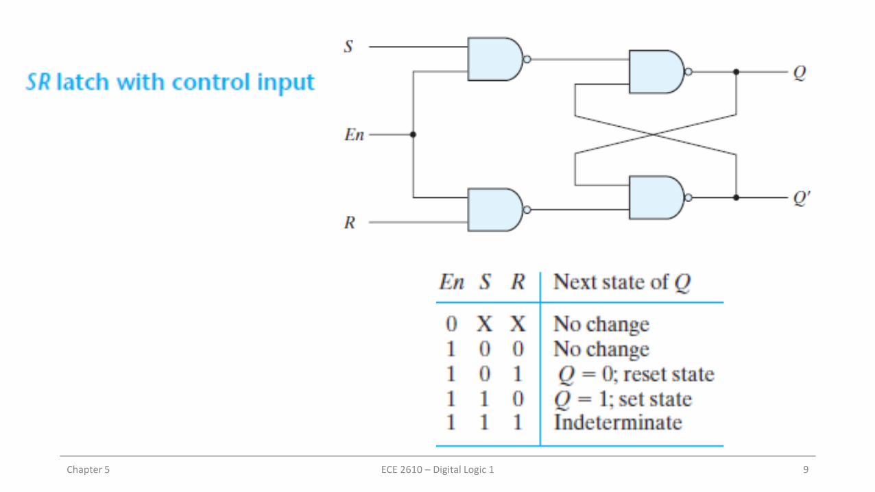
SR Latch
Chapter 5 ECE 2610 – Digital Logic 1 8
Chapter 5 ECE 2610 – Digital Logic 1 9
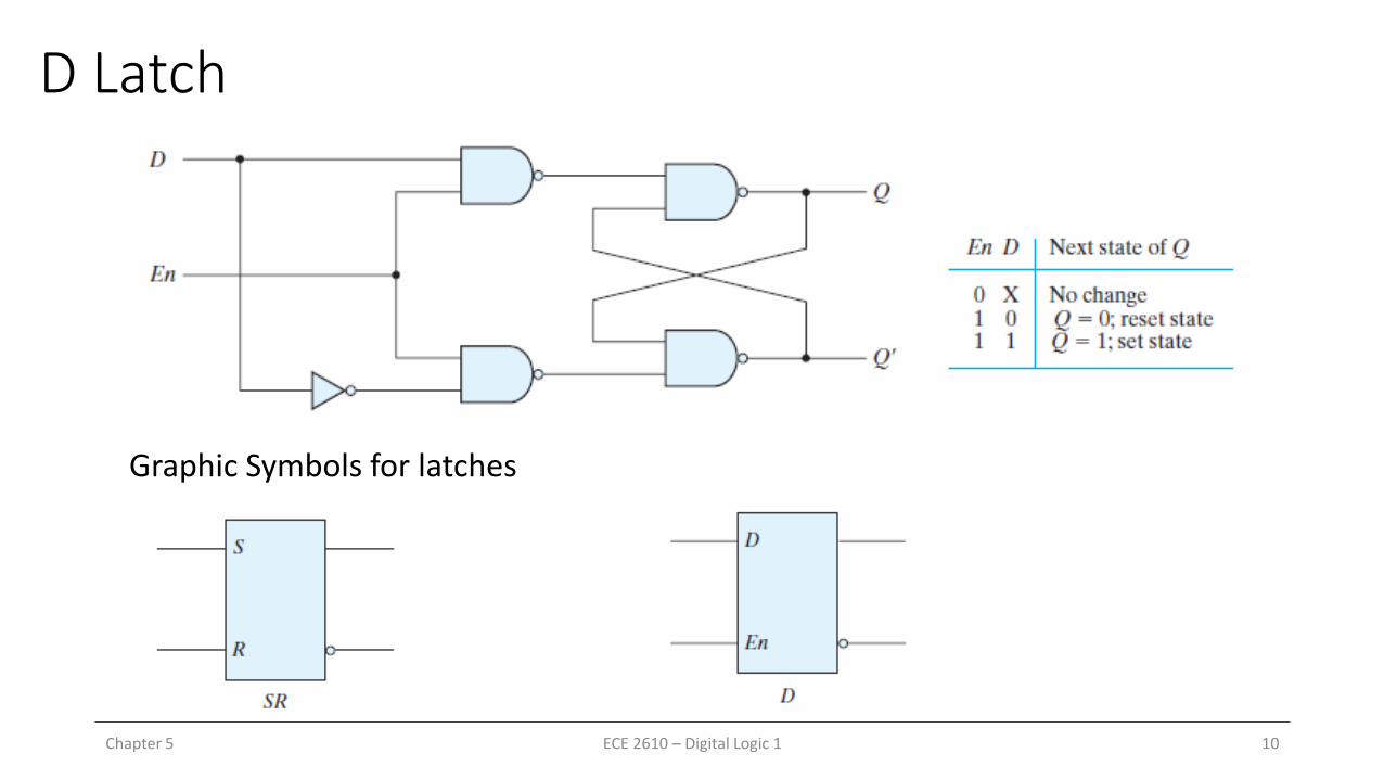
D Latch
Chapter 5 ECE 2610 – Digital Logic 1 10
Graphic Symbols for latches

Triggering
• Control input that changes the state of latch or flip-flop
Chapter 5 ECE 2610 – Digital Logic 1 11

Master Slave D Flip-flop (Positive edge triggered)• When clock changes to logic-0, External data input D is transferred to
the output of the master.
• When 𝑐𝑙𝑘 = 1, slave is enabled, and master is disabled. Hence, the output will be 𝑄 = 𝑃
Chapter 5 ECE 2610 – Digital Logic 1 12

S-R Flip-flop
Chapter 5 ECE 2610 – Digital Logic 1 13

J-K Flip-flop
Chapter 5 ECE 2610 – Digital Logic 1 14
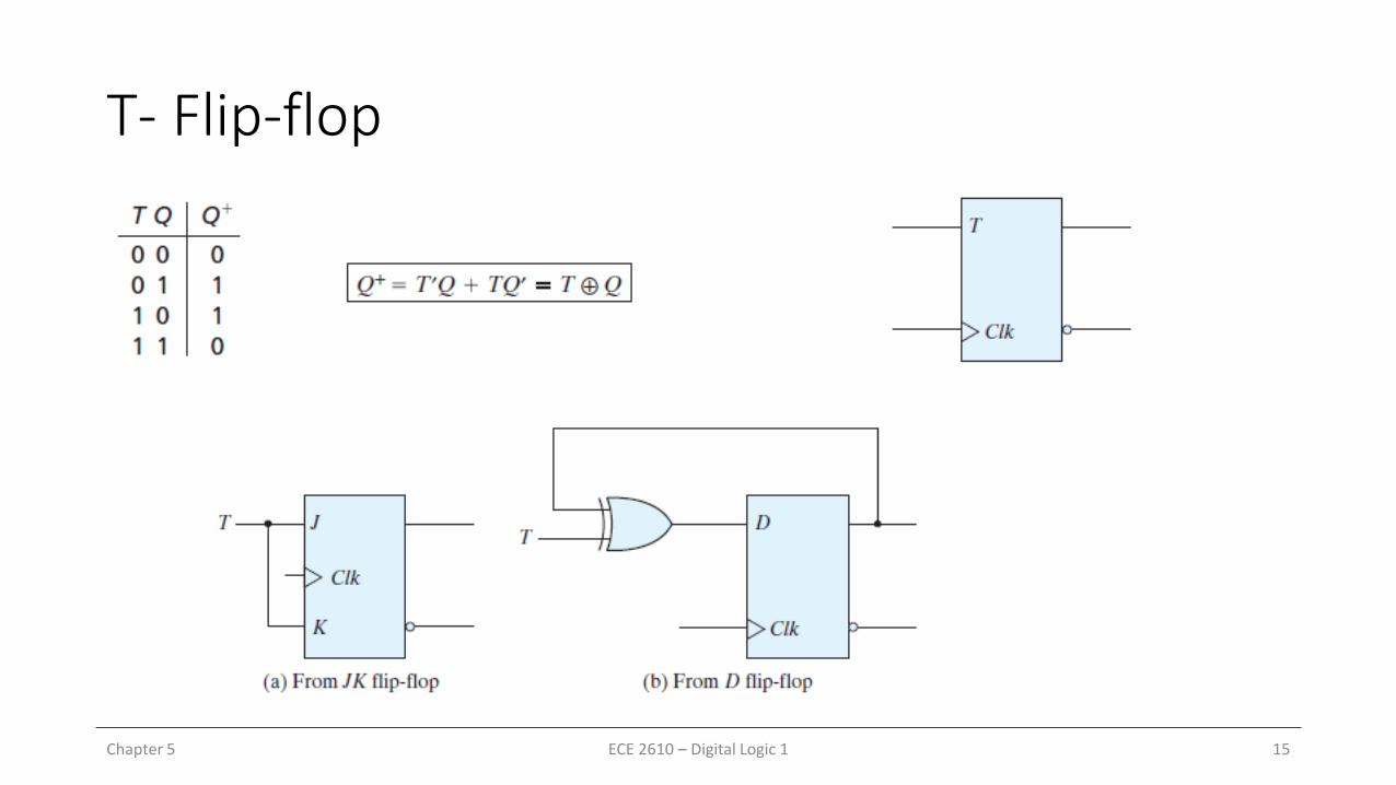
T- Flip-flop
Chapter 5 ECE 2610 – Digital Logic 1 15

Summary
• What are the differences between latches and flip-flops
• How to design a S-R latch?
• How to design a D flip-flop?
• Define setup and hold time in a D flip-flop?
• What are the other flip-flops?
Chapter 5 ECE 2610 – Digital Logic 1 16

Homework – 5 – Part a
• 5.2
• 5.4
Chapter 5 ECE 2610 – Digital Logic 1 17