lecture 12 (ac power) - overhead
DESCRIPTION
electrical circuitsTRANSCRIPT

University of British Columbia Elec Machines & Electronics
EECE 365 – Winter 2012 Lecture 12: AC Power Systems
Nathan Ozog © 2013 Page 1 of 12
AC Power Systems
Power Grid
University of British Columbia Elec Machines & Electronics
EECE 365 – Winter 2012 Lecture 12: AC Power Systems
Nathan Ozog © 2013 Page 2 of 12
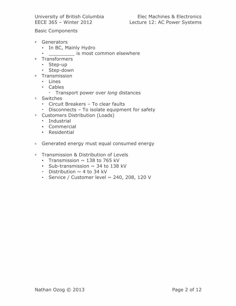
Basic Components
Generators
In BC, Mainly Hydro is most common elsewhere
Transformers Step-up
Step-down Transmission
Lines Cables
Transport power over long distances Switches
Circuit Breakers – To clear faults Disconnects – To isolate equipment for safety
Customers Distribution (Loads)
Industrial Commercial
Residential
Generated energy must equal consumed energy
Transmission & Distribution of Levels Transmission ~ 138 to 765 kV
Sub-transmission ~ 34 to 138 kV Distribution ~ 4 to 34 kV
Service / Customer level ~ 240, 208, 120 V
University of British Columbia Elec Machines & Electronics
EECE 365 – Winter 2012 Lecture 12: AC Power Systems
Nathan Ozog © 2013 Page 3 of 12
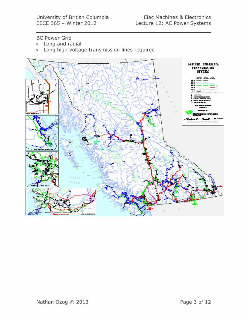
BC Power Grid Long and radial
Long high voltage transmission lines required
University of British Columbia Elec Machines & Electronics
EECE 365 – Winter 2012 Lecture 12: AC Power Systems
Nathan Ozog © 2013 Page 4 of 12
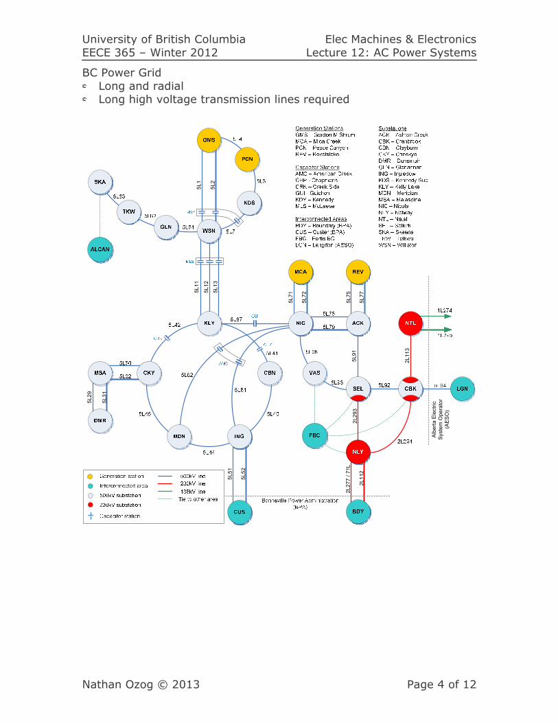
BC Power Grid
Long and radial Long high voltage transmission lines required
5L11
5L12
5L13
5L29
5L31
5L51
5L52
5L71
5L72
5L75
5L77
5L1
5L2
2L112
2L277 / 71L
Alberta Electric
System Operator
(AESO)
5L91
2L113
2L293
University of British Columbia Elec Machines & Electronics
EECE 365 – Winter 2012 Lecture 12: AC Power Systems
Nathan Ozog © 2013 Page 5 of 12
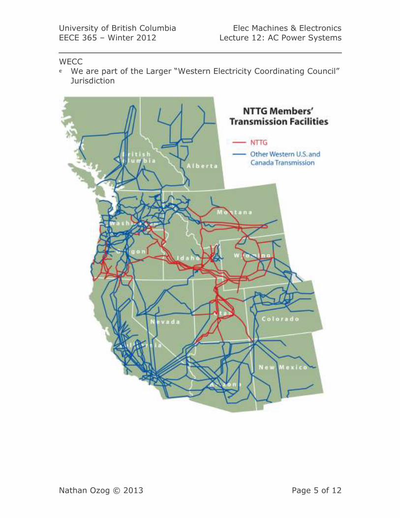
WECC We are part of the Larger “Western Electricity Coordinating Council”
Jurisdiction
University of British Columbia Elec Machines & Electronics
EECE 365 – Winter 2012 Lecture 12: AC Power Systems
Nathan Ozog © 2013 Page 6 of 12
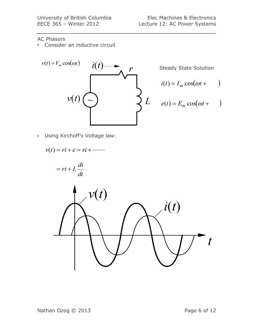
AC Phasors Consider an inductive circuit
Using Kirchoff’s Voltage law:
Steady State Solution
( )
( )+=
+=
tEte
tIti
m
m
ω
ω
cos)(
cos)(
( )tVtv m ωcos)( =
dt
diLri
rieritv
+=
+=+=)(
University of British Columbia Elec Machines & Electronics
EECE 365 – Winter 2012 Lecture 12: AC Power Systems
Nathan Ozog © 2013 Page 7 of 12
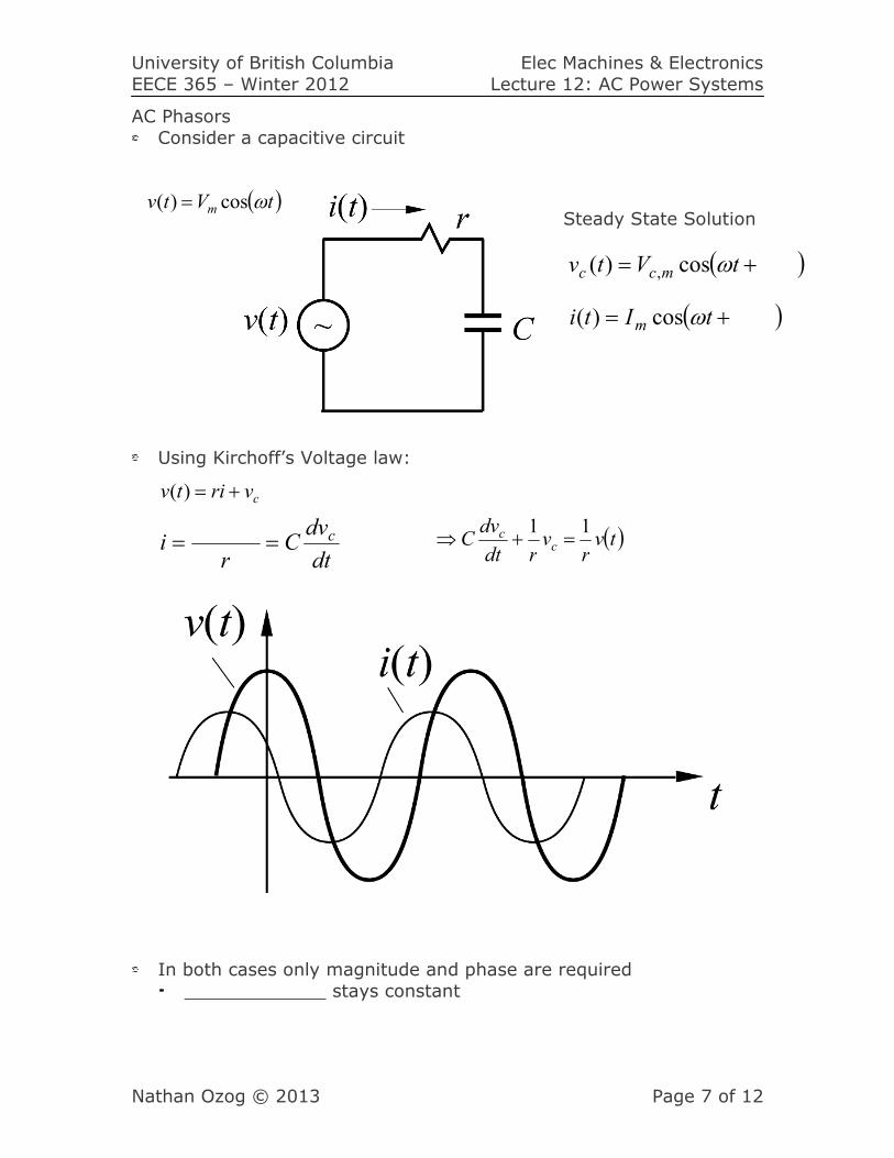
AC Phasors
Consider a capacitive circuit
Using Kirchoff’s Voltage law:
In both cases only magnitude and phase are required
stays constant
Steady State Solution
( )+= tIti m ωcos)(
( )+= tVtv mcc ωcos)( ,
( )tVtv m ωcos)( =
cvritv +=)(
dt
dvC
ri c== ( )tv
rvrdt
dvC c
c 11=+⇒
University of British Columbia Elec Machines & Electronics
EECE 365 – Winter 2012 Lecture 12: AC Power Systems
Nathan Ozog © 2013 Page 8 of 12
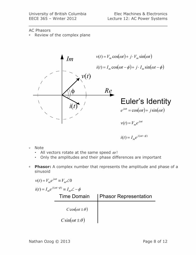
AC Phasors Review of the complex plane
Note All vectors rotate at the same speed ω !
Only the amplitudes and their phase differences are important
Phasor: A complex number that represents the amplitude and phase of a
sinusoid
Time Domain
( )θω ±tC cos
Phasor Representation
( ) ( )tVjtVtv mm ωω sincos)( ⋅+=
( ) ( )φωφω −⋅+−= tIjtIti mm sincos)(
)()(
)(
φω
ω
−=
=
tjm
tjm
eIti
eVtv
Euler’s Identity ( ) ( )tjte tj ωωω sincos +=
φφω −∠≡= −m
tjm IeIti )()(
0)( ∠≡= mtj
m VeVtv ω
( )θω ±tC sin
University of British Columbia Elec Machines & Electronics
EECE 365 – Winter 2012 Lecture 12: AC Power Systems
Nathan Ozog © 2013 Page 9 of 12
AC Phasors
Can be described in:
Polar: φ∠mC
Rectangular: jBA+
Conversion:
Rectangular � polar
=mC =φ
Polar � rectangular
=
=
B
A
Addition of Phasors Use rectangular notation
[ ] [ ]=+++=+ 2211 jBAjBAjBA tt
So 21
21
BBB
AAA
t
t
+=
+=
Multiplication of Phasors
[ ] [ ]=∠⋅∠=∠ 2211 φφφ CCC tt
Division of Phasors
∠=∠∠
=∠22
11
φφ
φC
CC tt
University of British Columbia Elec Machines & Electronics
EECE 365 – Winter 2012 Lecture 12: AC Power Systems
Nathan Ozog © 2013 Page 10 of 12
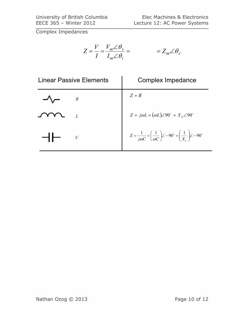
Complex Impedances
C
L
Linear Passive Elements
RRZ =
Complex Impedance
( ) oo 9090 ∠=∠== LXLLjZ ωω
oo 901
9011
−∠
=−∠
==
cXCCjZ
ωω
zmim
vm ZI
V
I
VZ θ
θθ
∠==∠∠
==
University of British Columbia Elec Machines & Electronics
EECE 365 – Winter 2012 Lecture 12: AC Power Systems
Nathan Ozog © 2013 Page 11 of 12
2
2
0
2
0
2
0
2
0
1
)(11
)(11
)(1
)(1
rms
V
T
T
T
T
ave
vr
dttvTr
dttvTr
dtr
tv
T
dttPT
P
rms
=
=
⋅=
=
=
∫
∫
∫
∫
4434421
2
2
0
2
0
2
0
2
0
)(1
)(1
)(1
)(1
rms
i
T
T
T
T
ave
ri
dttiT
r
dttiT
r
rdttiT
dttPT
P
rms
=
=
⋅=
=
=
∫
∫
∫
∫
4434421
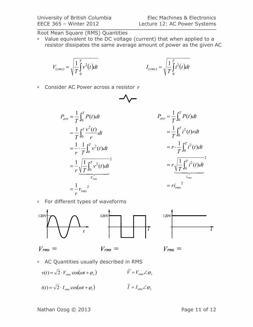
Root Mean Square (RMS) Quantities
Value equivalent to the DC voltage (current) that when applied to a resistor dissipates the same average amount of power as the given AC
Consider AC Power across a resistor r
For different types of waveforms
AC Quantities usually described in RMS
( )∫=T
rms dttvT
V0
2)(
1 ( )∫=T
rms dttiT
I0
2)(
1
( )vrms tVtv ϕω +⋅= cos2)(
( )irms tIti ϕω +⋅= cos2)(
vrmsVV ϕ∠=~
vrmsII ϕ∠=~
University of British Columbia Elec Machines & Electronics
EECE 365 – Winter 2012 Lecture 12: AC Power Systems
Nathan Ozog © 2013 Page 12 of 12
( )
( )
( ) ( ) ( )
=
+==
+⋅=
⋅=
ϕωω
ϕω
ω
ttVIvitp
tIti
tVtv
rms
rms
coscos2
cos2)(
cos2)(
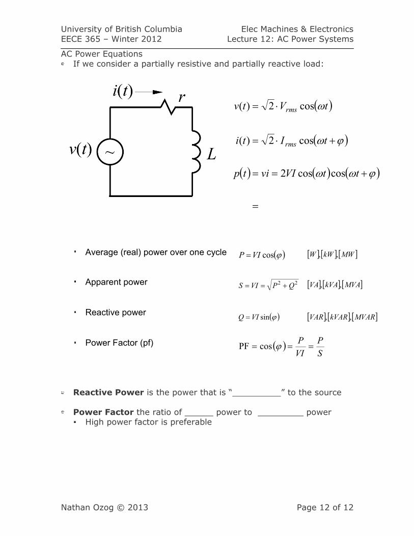
AC Power Equations
If we consider a partially resistive and partially reactive load:
Average (real) power over one cycle
Apparent power
Reactive power
Power Factor (pf)
Reactive Power is the power that is “ ” to the source
Power Factor the ratio of power to power High power factor is preferable
( )S
P
VI
P=== ϕcosPF
( )ϕsinVIQ =
22 QPVIS +== [ ] [ ] [ ]MVAkVAVA ,,
[ ] [ ] [ ]MVARkVARVAR ,,
( )ϕcosVIP = [ ] [ ] [ ]MWkWW ,,