lecture 12: wireless physical and link layers · - 802.11b: barker code (1-2mbps), complementary...
TRANSCRIPT
Lecture 12: Wireless Physical and LinkLayers
Static Routing is due today
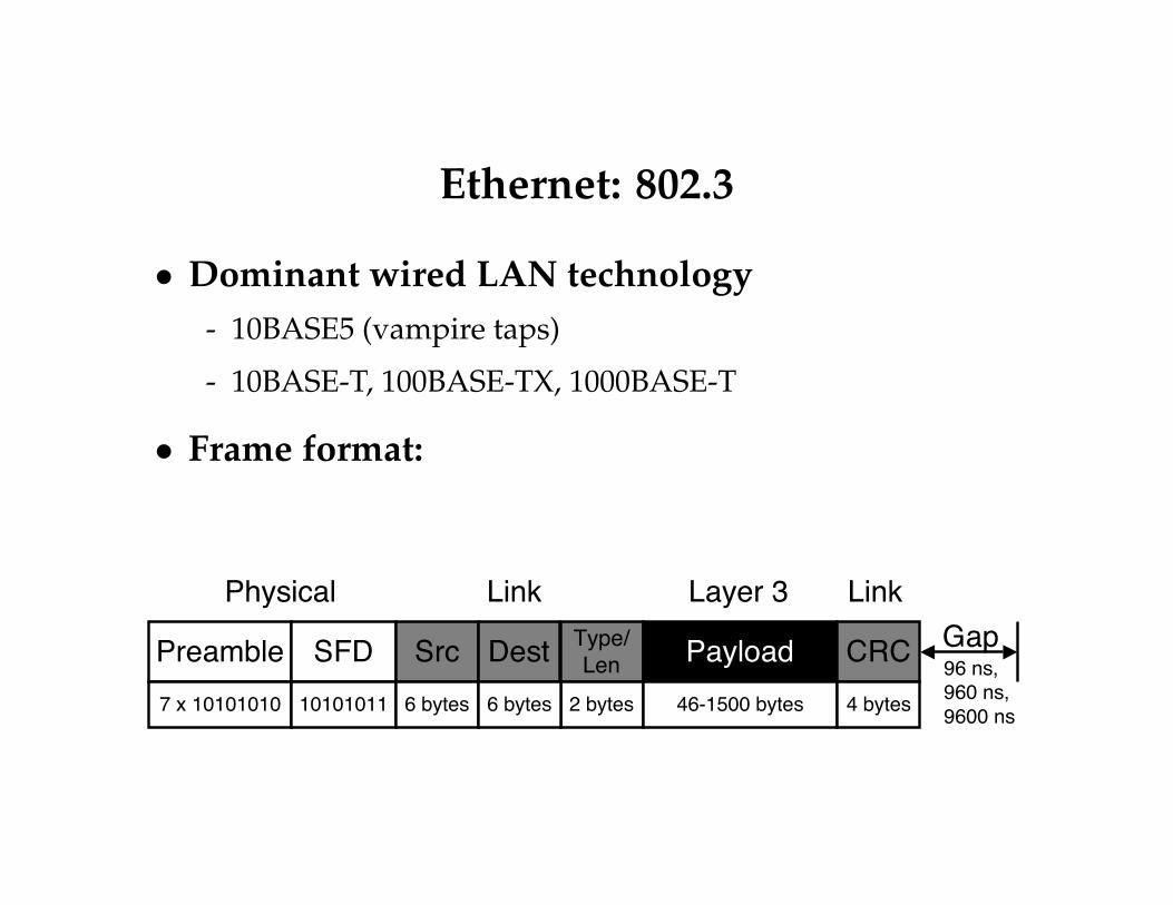
Ethernet: 802.3
• Dominant wired LAN technology- 10BASE5 (vampire taps)
- 10BASE-T, 100BASE-TX, 1000BASE-T
• Frame format:
Preamble Type/Len Payload
7 x 10101010
SFD10101011
Src6 bytes 2 bytes 46-1500 bytes
CRC4 bytes
Gap96 ns,960 ns,9600 ns
Physical Link LinkLayer 3
Dest6 bytes

Physical Layer (Layer 1)
• Responsible for specifying the physical medium- Category 5 cable (Cat5): 8 wires, twisted pair, RJ45 jack
- WiFi wireless: 2.4GHz
• Responsible for specifying the signal- 100BASE-T: 5-level pulse amplitude modulation (PAM-5)
- 802.11b: Binary and quadrature phase shift keying(BPSK/QPSK)
• Responsible for specifying the bits- 100BASE-T: 4-to-6 bit-to-chip encoding, 3 chip symbols
- 802.11b: Barker code (1-2Mbps), complementary codekeying (5.5-11Mbps)

Wireless is Different
• Variable: signal attenuates over space
• Interference: other RF sources can interfere withsignal
• Multipath: signal can self-interfere
• Distributed: nodes cannot detect collisions
• To address these differences, wireless link layersuse slightly different mechanisms

Attenuation Over Space
• Signal weakens as distance from transmitterincreases
• Reflections, obstructions, etc. complicate theattenuation
• Depending on the antenna, not uniform in alldirections
• Much more complex than the wired model

Signal Strength Over Space

Directional Antennas

Interference
• In unlicensed bands (e.g., 802.11), there are lots oftransmitters
- 802.11 cards
- 802.15.1 (Bluetooth)
- 802.15.4 (ZigBee)
- 2.4GHz phones
- Microwave ovens
• This interference can be stronger or weaker thanthe signal, and can prevent successful reception

Analog Signals
Amplitude
Wavelength

Specifying the Signal: Modulation
On-Off Keying(OOK)
1 0 1
Amplitude ShiftKeying (ASK)
1 0 1

Modulation, Continued
Frequency ShiftKeying (FSK)
1 0 1
Phase ShiftKeying (PSK)
1 0 1

I/Q Modulation
• I: in-phase, Q: quadrature
• Sum of two sines is a sine
• Show what the carrier looks like compared to asimple, unmodulated signal
• Use I/Q because this is how it’s actually done inhardware

I+Q

Modulation in I/Q Plots
Q Q Q Q
I
Q
OOK ASK FSK BPSK QPSK

Signal, Noise, and Interference
• Signal: energy of desired transmission
• Noise/Noise floor: energy of hardware thermaleffects
• Interference: energy of other transmitters
• Usually measured in dBm/dBW: 0dBm = 1mW,0dBW = 30dBm = 1W
- Note dB is a logarithmic scale: 10dBm = 10mW, 20dBm =100mW

Signal Plus Noise

SINR
• Signal to Interference-and-Noise Ratio
• Measured in dB: |S ||N+I |
- S = -50dBm, N+I = -95dBm, SINR = 35dB
- S = -89dBm, N+I = -93dBm, SINR = 4dB

Bit Error Rates
• There is a theoretical limit on how muchinformation a channel can carry
• Bit error rate depends on the SINR and themodulation
• This is why wireless link layers use more complexchip/bit encoding

2-3
After the signal is received and digitized, it is fed through aseries of adaptive delay stages which are summed togethervia feedback loops. This technique is particularly effective inslowly changing environments such as transmission overtelephone lines, but is more difficult to implement in rapidlychanging environments like factory floors, offices and homeswhere transmitters and receivers are moving in relation toeach other. The main drawback is the impact on system costand complexity. Adaptive equalizers can be expensive toimplement for broadband data links.
Spread spectrum systems are fairly robust in the presenceof multipath. Direct Sequence Spread Spectrum (DSSS)systems will reject reflected signals which are significantlydelayed relative to the direct path or strongest signal. This isthe same property which allows multiple users to share thesame bandwidth in Code Diversity Multiple Access (CDMA)systems. Frequency Hopping Spread Systems (FHSS) alsoexhibit some degree of immunity to multipath. Because aFHSS transmitter is continuously changing frequencies, itwill always hop to some frequencies which experience littleor no multipath loss. In a severe fading environment,throughput of an FHSS system will be reduced, but it isunlikely that the link will be lost completely. The performanceof DSSS systems in the presence of multipath is describedfurther in a separate section below.
Modulation TechniqueModulation technique is a key consideration. This is themethod by which the analog or digital information isconverted to signals at RF frequencies suitable fortransmission. Selection of modulation method determinessystem bandwidth, power efficiency, sensitivity, andcomplexity. Most of us are familiar with AmplitudeModulation (AM) and Frequency Modulation (FM) becauseof their widespread use in commercial radio. PhaseModulation is another important technique. It is used inapplications such as Global Position System (GPS)receivers and some cellular telephone networks.
For the purposes of link budget analysis, the most importantaspect of a given modulation technique is the Signal-to-Noise Ratio (SNR) necessary for a receiver to achieve aspecified level of reliability in terms of BER. A graph of Eb/Novs BER is shown in Figure 4. Eb/No is a measure of therequired energy per bit relative to the noise power. Note thatEb/No is independent of the system data rate. In order toconvert from Eb/No to SNR, the data rate and systembandwidth must be taken into account as shown below:
where:
Eb = Energy required per bit of information
No= thermal noise in 1Hz of bandwidth
R = system data rate
BT= system bandwidth
Spread Spectrum RadiosThe term “spread spectrum” simply means that the energyradiated by the transmitter is spread out over a wider amountof the RF spectrum than would otherwise be used. Byspreading out the energy, it is far less likely that two userssharing the same spectrum will interfere with each other.This is an important consideration in an unlicensed band,which why the regulatory authorities imposed spreadspectrum requirements on radios which transmit over -1dBm(about 0.75mW) in the following bands:
FIGURE 3. ADAPTIVE EQUALIZER
∑
W1 W2 W3 W4 Wn
Z-1 Z-1 Z-1 Z-1
DIGITAL EQUALIZER OUT
DIGITIZEDBASEBANDINPUT
TABLE 1. TYPICAL BANDWIDTHS FOR VARIOUS DIGITALMODULATION METHODS
MODULATION METHODTYPICAL BANDWIDTH
(NULL-TO-NULL)
QPSK, DQPSK 1.0 x Bit Rate
MSK 1.5 x Bit Rate
BPSK, DBPSK, OFSK 2.0 x Bit Rate
FIGURE 4. PROBABILITY OF BIT ERROR FOR COMMONMODULATION METHODS
0 1 2 3 4 5 6 7 8 9 10 11 12 13 14 15Eb/No (dB)
1.0E-01
1.0E-02
1.0E-03
1.0E-04
1.0E-05
1.0E-06
1.0E-07
BE
INCOHERENT OOK, OFSK
COHERENT OOK, OFSK
DBPSK, DQPSK
MSK, PSK
(EQ.4)SNR = (Eb/No) * (R/BT)
Application Note 9804

Example: 802.11b
• 11-chip Barker sequence: 10110111000
• Binary Phase Shift Keying (BPSK)
• SYNC, SFD, signal, service, length, CRC, data
• Service field reserved, length is in us
2005/1/345
CN@Lab
DS PLCP
FramingThe FH PHY uses a data whitener to randomize the data before transmission, but the data whitener applies only to the MAC frame.The DS PHY uses a scrambler and applies to PLCP header+preamble+MAC frame.

Variable Bit Rates
• 802.11b supports 1, 2, 5.5, and 11Mbps
• 2, 5.5Mbps and 11Mbps are QPSK
• To support this, the signal field says what the datarate is
- 00001010: 1Mbps (11 chips/bit, barker code)
- 00010100: 2Mbps (11 chips/bit, barker code)
- 00110111: 5.5Mbps (2 chips/bit, CCK)
- 01101110: 11Mbps (1 chip/bit, CCK)
• So the header is still at 1Mbps, even if the data isat 11Mbps
• CCK is rather complex: don’t worry about it

802.11 Packet Loss Rates

802.11 Packet Loss Rates (at 11Mbps)
0.0 0.2 0.4 0.6 0.8 1.0Packet Reception Ratio
0%
20%
40%
60%
80%
100%
% L
inks
• How does this affect TCP?

Wireless PHY Summary
• Can’t control or limit the channel
• Need to deal with weak signals, interference, etc.
• Many different kinds of modulation: amplitude,frequency, phase
• Use robust encodings when needed, use fastspeeds when possible
• Lots of intermediate packet delivery ratios

2 minute break

MAC Layer Responsibilities
• Arbitrate control of the channel
• One node should be able to use 100%
• Multiple nodes should get a fair share
• Want high utilization under contention
CA versus CD
• Collision detect (CD) is hard in wireless
• Local signal is much stronger than anythingreceived
• Protocols use collision avoidance (CA) by sensingthe channel
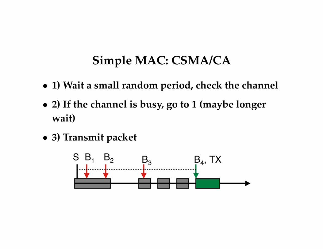
Simple MAC: CSMA/CA
• 1) Wait a small random period, check the channel
• 2) If the channel is busy, go to 1 (maybe longerwait)
• 3) Transmit packet
B1 B2 B3 B4, TXS

802.11b MAC: CSMA/CA
• Maintain a waiting counter c
• For each time step channel is idle, c −−
• When c = 0, transmit
• If packet is not acknowledged (layer 2), pick a new,larger c
- Use lack of layer 2 ack as collision detect
B1, TX B2, ACKS

Problems with CSMA/CA
• Want to know state of channel at receiver, nottransmitter
• But wireless is not transitive!- A hears B
- A hears C
- B and C may not hear each other
- B and C can only sense their channel, but need to know ifA’s channel is clear

Hidden Terminal Problem
B A C

Exposed Terminal Problem
B A C

RTS/CTS
• Request-to-send, Clear-to-send (RTS/CTS)
• Allows transmitter to check availability of channelat receiver
• Transmitter sends an RTS
• If it hears a CTS, sends data
• If not, retries RTS some time later
• If you hear a CTS for someone else, don’t transmit

RTS
B A CRTS

CTS
B A CCTS
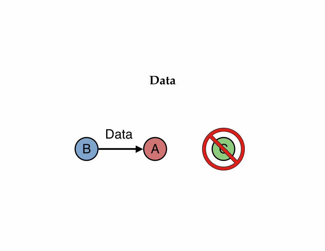
Data
B A CData
Network Allocation Vector (NAV)
• 802.11b supports RTS/CTS
• NAV is data structure node uses to know whenchannel may be clear
• NAV is in terms of time: variable bit rates, RTS,etc.

RTS/CTS Benefits
• Solves the hidden terminal problem (assumingCTS not corrupted)
• Improves packet delivery ratio
• Does it solve the exposed terminal problem? Whatabout ACKs?
B A C

RTS/CTS Drawbacks
• 3 packets per packet: RTS/CTS/DATA
• RTS still go through CSMA: they can be lost
• CTS losses cause lengthy retries
• 33% of IP packets are TCP ACKs: is it worth it?
• In practice, WiFi doesn’t use RTS/CTS