lecture 2 - fundamentals september, 2011 ce 370. lecture goals design process limit states design...
TRANSCRIPT

Lecture 2 - Lecture 2 - FundamentalsFundamentals
September, 2011CE 370

Lecture GoalsLecture Goals
Design ProcessLimit statesDesign PhilosophyLoading

Design ProcessDesign Process
Phase 1: Definition of clients’ needs and priorities. Functional requirements
Aesthetic requirements
Budgetary requirements

Design ProcessDesign Process
Phase 2: Development of project concept Develop possible layouts
Approximate analysis preliminary members sizes/cost for each arrangement
Design ProcessDesign Process
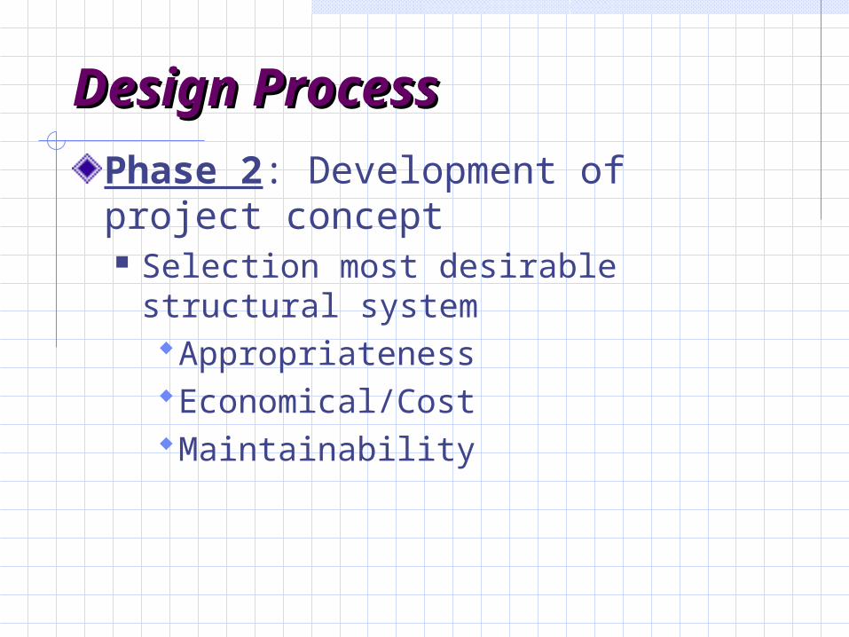
Phase 2: Development of project concept Selection most desirable structural
systemAppropriatenessEconomical/CostMaintainability
Design ProcessDesign Process
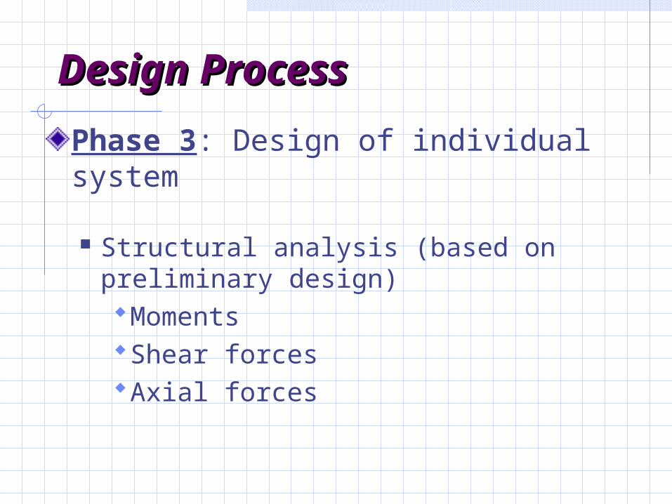
Phase 3: Design of individual system
Structural analysis (based on preliminary design)MomentsShear forcesAxial forces

Design ProcessDesign ProcessPhase 3: Design of individual system(cont.)
Member designPrepare construction days and
specifications. Proportion members to resist forces
aesthetics constructability maintainability

Limit States and DesignLimit States and Design
Limit State: Condition in which a structure or structural
element is no longer acceptable for its intended use.
Major groups for RC structural limit statesUltimateServiceabilitySpecial

Ultimate Limit StateUltimate Limit State
Ultimate limit state structural collapse of all or part of the
structure ( very low probability of occurrence) and loss of life can occur.
Loss of equilibrium of a part or all of a structure as a rigid body (tipping, sliding of structure).
Ultimate Limit StatesUltimate Limit States
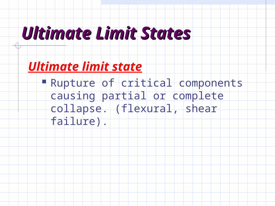
Ultimate limit state Rupture of critical components
causing partial or complete collapse. (flexural, shear failure).

Ultimate Limit StatesUltimate Limit States
Progressive Collapse Minor local failure overloads causing
adjacent members to failure entire structure collapses.
Structural integrity is provided by tying the structure together with correct detailing of reinforcement provides alternative load paths in case of localized failure
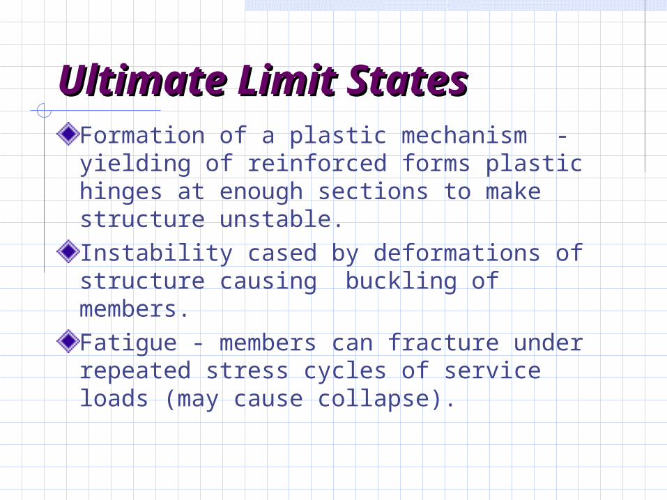
Ultimate Limit StatesUltimate Limit StatesFormation of a plastic mechanism - yielding of reinforced forms plastic hinges at enough sections to make structure unstable.Instability cased by deformations of structure causing buckling of members.Fatigue - members can fracture under repeated stress cycles of service loads (may cause collapse).
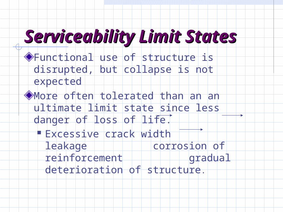
Serviceability Limit Serviceability Limit StatesStates
Functional use of structure is disrupted, but collapse is not expectedMore often tolerated than an an ultimate limit state since less danger of loss of life. Excessive crack width leakage
corrosion of reinforcement gradual deterioration of structure.
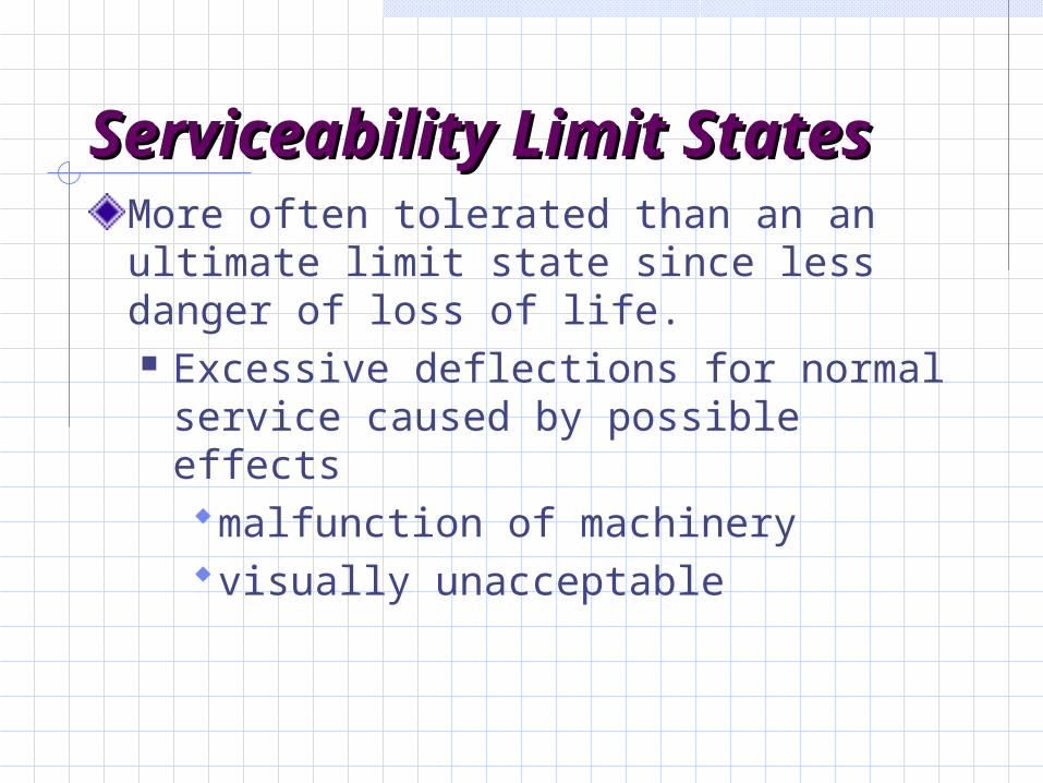
Serviceability Limit Serviceability Limit StatesStates
More often tolerated than an an ultimate limit state since less danger of loss of life. Excessive deflections for normal
service caused by possible effects malfunction of machineryvisually unacceptable

Serviceability Limit Serviceability Limit StatesStates
More often tolerated than an an ultimate limit state since less danger of loss of life. Excessive deflections for normal
service caused by possible effects damage of nonstructural elements changes in force distributionsponding on roofs collapse of
roof
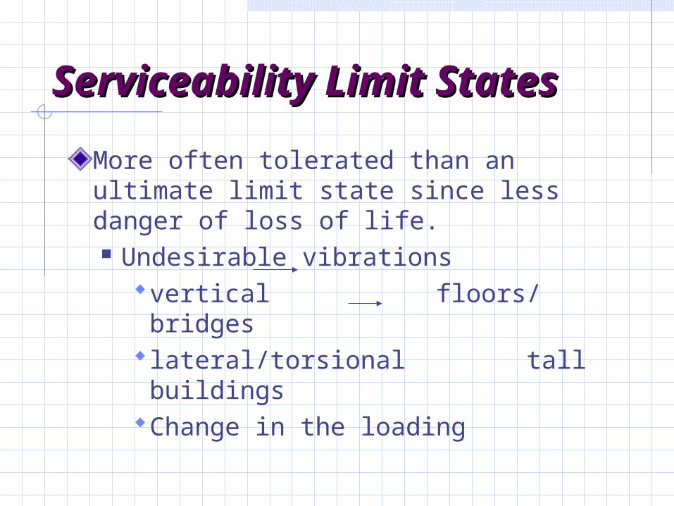
Serviceability Limit Serviceability Limit StatesStates
More often tolerated than an ultimate limit state since less danger of loss of life. Undesirable vibrations
vertical floors/ bridgeslateral/torsional tall buildings Change in the loading
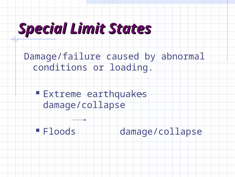
Special Limit StatesSpecial Limit States
Damage/failure caused by abnormal conditions or loading.
Extreme earthquakes damage/collapse
Floods damage/collapse

Special Limit StatesSpecial Limit StatesDamage/failure caused by abnormal
conditions or loading.
Effects of fire,explosions, or vehicular collisions.
Effects of corrosion, deterioration Long-term physical or chemical
instability

Limit States DesignLimit States Design
Identify all potential modes of failure.
Determine acceptable safety levels for normal structures building codes load combination/factors.
Limit States DesignLimit States Design
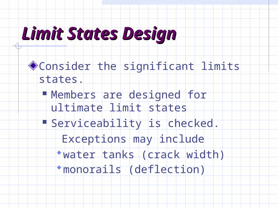
Consider the significant limits states. Members are designed for ultimate
limit states Serviceability is checked. Exceptions may include
water tanks (crack width)monorails (deflection)
ACI Building CodesACI Building Codes
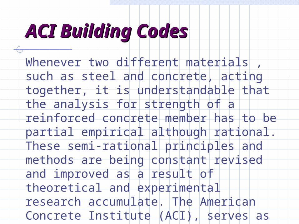
Whenever two different materials , such as steel and concrete, acting together, it is understandable that the analysis for strength of a reinforced concrete member has to be partial empirical although rational. These semi-rational principles and methods are being constant revised and improved as a result of theoretical and experimental research accumulate. The American Concrete Institute (ACI), serves as clearing house for these changes, issues building code requirements.

Design PhilosophyDesign Philosophy
Two philosophies of design have long prevalent.
• Working stress method focuses on conditions at service loads.
• Strength of design method focusing on conditions at loads greater than the service
loads when failure may be imminent.
The strength design method is deemed conceptually more realistic to establish structural safety.
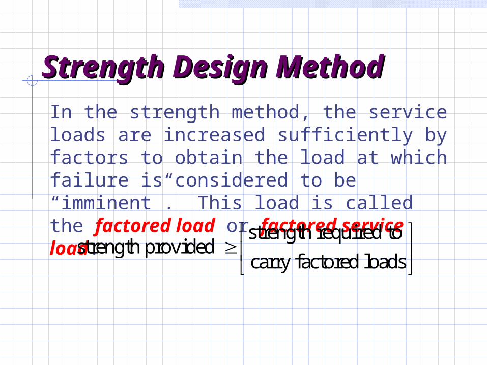
Strength Design Strength Design MethodMethodIn the strength method, the service loads are increased sufficiently by factors to obtain the load at which failure is considered to be “imminent”. This load is called the factored load or factored service load.
strength required to strength provided
carry factored loads
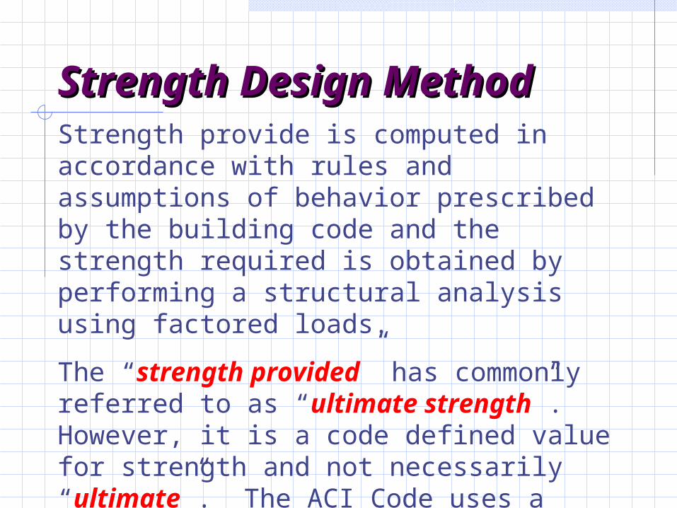
Strength Design Strength Design MethodMethodStrength provide is computed in accordance with rules and assumptions of behavior prescribed by the building code and the strength required is obtained by performing a structural analysis using factored loads.
The “strength provided” has commonly referred to as “ultimate strength”. However, it is a code defined value for strength and not necessarily “ultimate”. The ACI Code uses a conservative definition of strength.

Safety ProvisionsSafety Provisions
Structures and structural members must always be designed to carry some reserve load above what is expected under normal use.
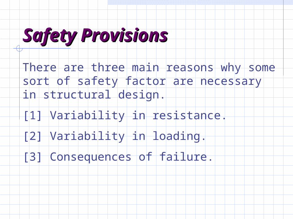
Safety ProvisionsSafety Provisions
There are three main reasons why some sort of safety factor are necessary in structural design.
[1] Variability in resistance.
[2] Variability in loading.
[3] Consequences of failure.
Variability in Variability in ResistanceResistance
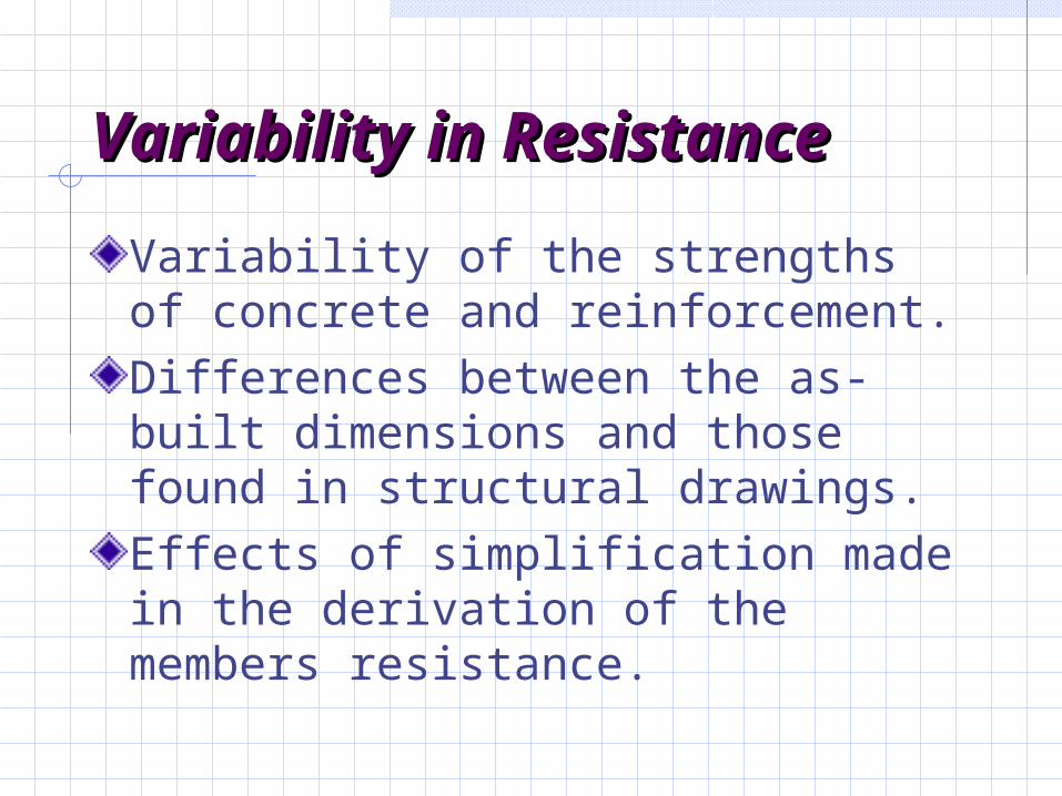
Variability of the strengths of concrete and reinforcement.Differences between the as-built dimensions and those found in structural drawings.Effects of simplification made in the derivation of the members resistance.
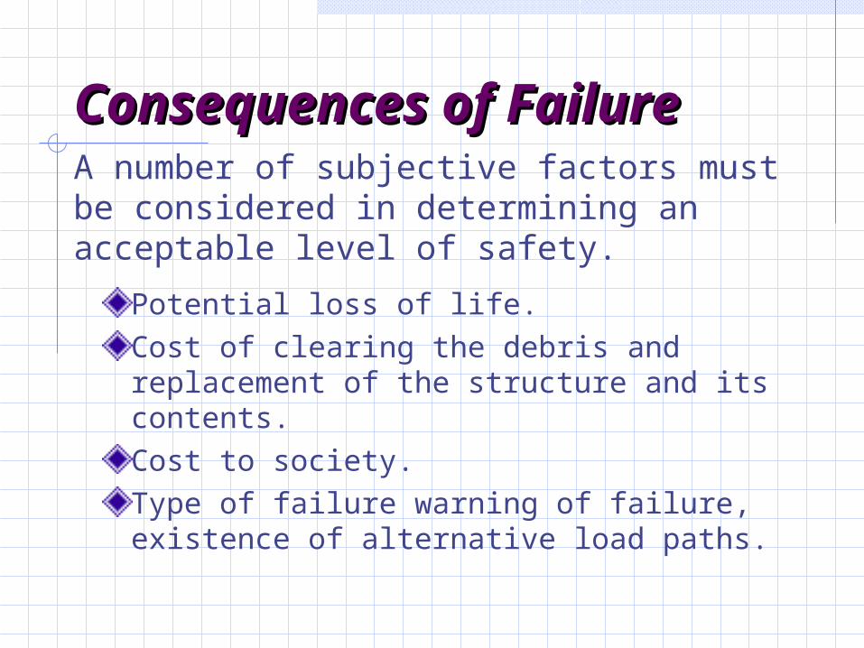
Consequences of Consequences of FailureFailure
Potential loss of life.Cost of clearing the debris and replacement of the structure and its contents.Cost to society.Type of failure warning of failure, existence of alternative load paths.
A number of subjective factors must be considered in determining an acceptable level of safety.
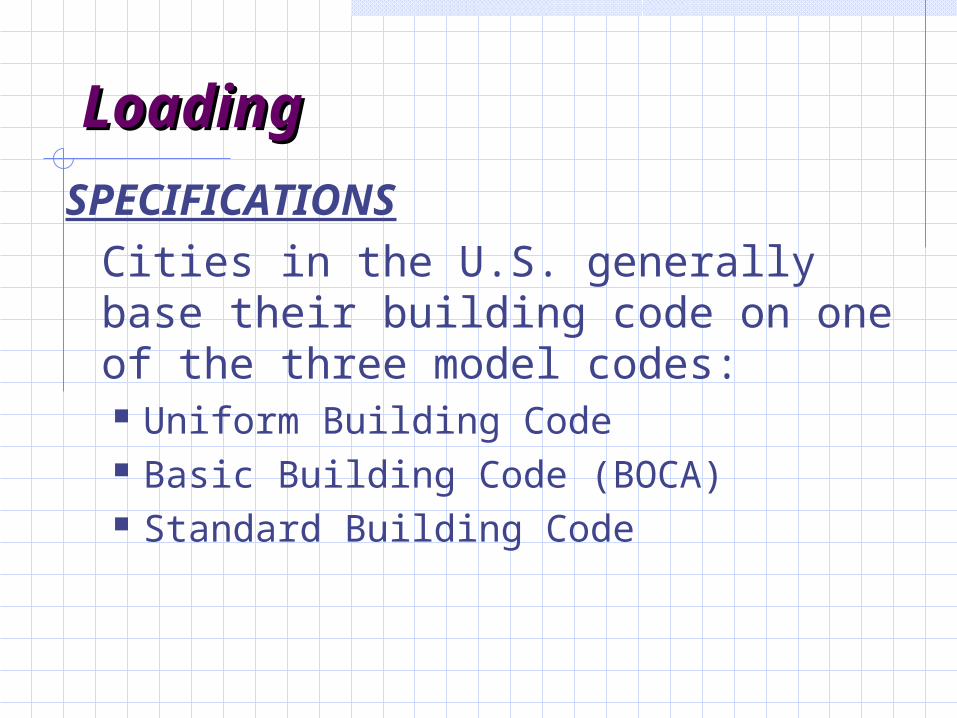
LoadingLoading
SPECIFICATIONSCities in the U.S. generally base their building code on one of the three model codes: Uniform Building Code Basic Building Code (BOCA) Standard Building Code

LoadingLoadingThese codes have been consolidated in the 2000 International Building Code.
Loadings in these codes are mainly based on ASCE Minimum Design Loads for Buildings and Other Structures (ASCE 7-98) – has been updated to ASCE 7-02.
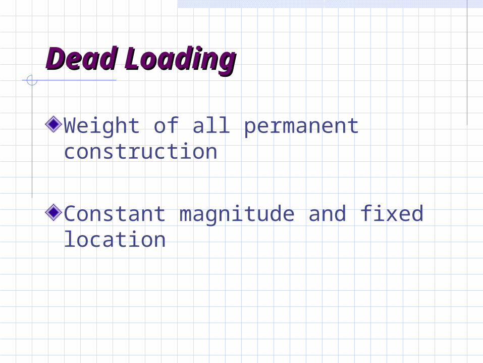
Dead LoadingDead Loading
Weight of all permanent construction
Constant magnitude and fixed location

Dead LoadsDead Loads
Examples: Weight of the Structure
(Walls, Floors, Roofs, Ceilings, Stairways)
Fixed Service Equipment(HVAC, Piping Weights, Cable Tray, Etc.)
Can Be Uncertain…. pavement thickness earth fill over underground structure

Live LoadsLive LoadsLoads produced by use and occupancy of the structure.Maximum loads likely to be produced by the intended use.Not less than the minimum uniformly distributed load given by Code.
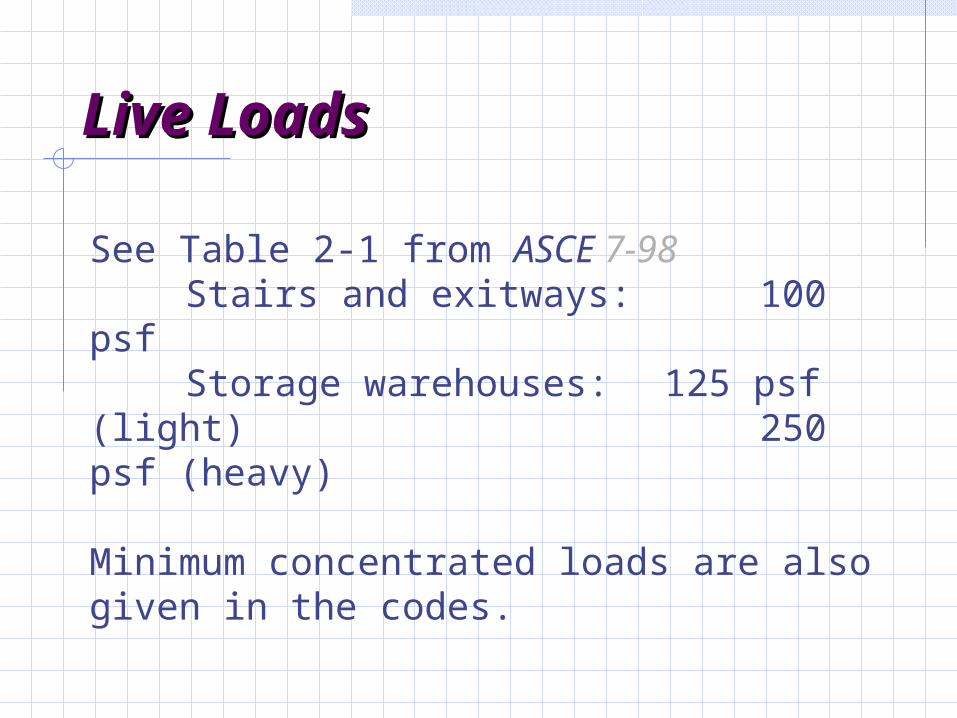
Live LoadsLive Loads
See Table 2-1 from ASCE 7-98 Stairs and exitways: 100 psfStorage warehouses: 125 psf
(light) 250 psf (heavy)
Minimum concentrated loads are also given in the codes.

Live LoadsLive Loads
Environmental LoadsEnvironmental Loads
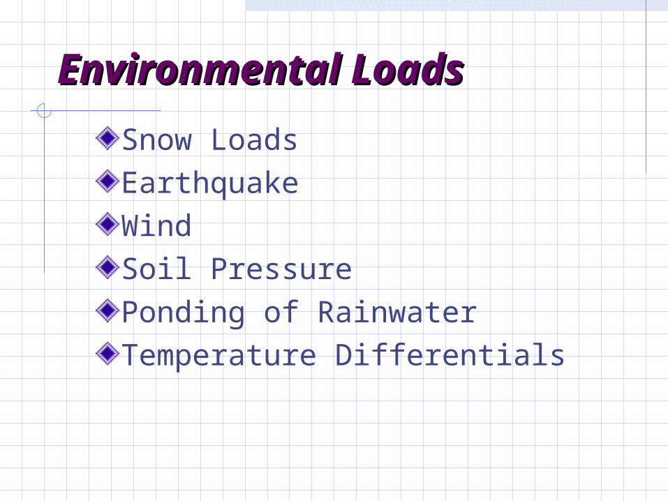
Snow LoadsEarthquakeWindSoil PressurePonding of RainwaterTemperature Differentials

Classification of Buildings for Classification of Buildings for Wind, Snow and Earthquake Wind, Snow and Earthquake LoadsLoads
Based on Use Categories (I through IV)
Buildings and other structures that represent a low hazard to human life in the event of a failure (such as agricultural facilities)
Buildings/structures not in categories I, III, and IV
I
II

Classification of Buildings for Classification of Buildings for Wind, Snow and Earthquake Wind, Snow and Earthquake LoadsLoads
Based on Use Categories (I through IV)
Buildings/structures that represent a substantial hazard to human life in the event of a failure (assembly halls, schools, colleges, jails, buildings containing toxic/explosive substances)
III

Classification of Buildings for Classification of Buildings for Wind, Snow and Earthquake Wind, Snow and Earthquake LoadsLoads
Based on Use Categories (I through IV)
Buildings/structures designated essential facilities (hospitals, fire and police stations, communication centers, power-generating stations)
IV

Snow LoadsSnow LoadsGround Snow Loads (Map in Fig. 6, ASCE 7):
Based on historical data (not always the maximum values)Basic equation in codes is for flat roof snow loadsAdditional equations for drifting effects, sloped roofs, etc.Use ACI live load factorNo LL reduction factor allowed

Wind LoadsWind LoadsWind pressure is proportional to velocity squared (v2 )
Wind velocity pressure = qz
IVkKq ztzz200256.0

Wind LoadsWind Loads
where 0.00256 reflects mass density of air and unit
conversions.V = Basic 3-second gust wind speed (mph) at a
height of 33 ft. above the ground in open terrain. (1:50 chance of exceedance in 1 year)
Kz = Exposure coefficient (bldg. ht., roughness of terrain)
kzt = Coefficient accounting for wind speed up over hills
I = Importance factor
IVkKq ztzz200256.0

Wind LoadsWind LoadsDesign wind pressure,
p = qz * G * Cp
G = Gust Response FactorCp = External pressure coefficients (accounts for
pressure directions on building)

Earthquake LoadsEarthquake LoadsInertia forces caused by earthquake motion
F = m * a
Distribution of forces can be found using equivalent static force procedure (code, not allowed for every building) or using dynamic analysis procedures

Earthquake LoadsEarthquake LoadsInertia forces caused by earthquake
motion. Equivalent Static Force Procedure for example, in ASCE 7-95:
V = Cs * W
whereV = Total lateral base shearCs = Seismic response coefficient
W = Total dead load
Earthquake LoadsEarthquake Loads
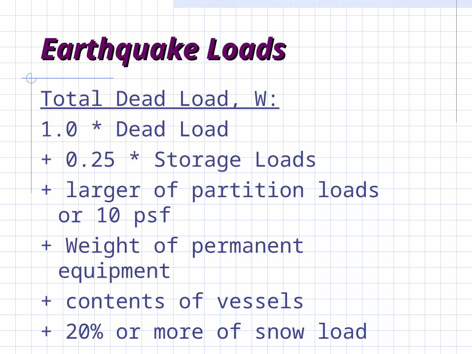
Total Dead Load, W:1.0 * Dead Load + 0.25 * Storage Loads + larger of partition loads or 10 psf + Weight of permanent equipment + contents of vessels + 20% or more of snow load
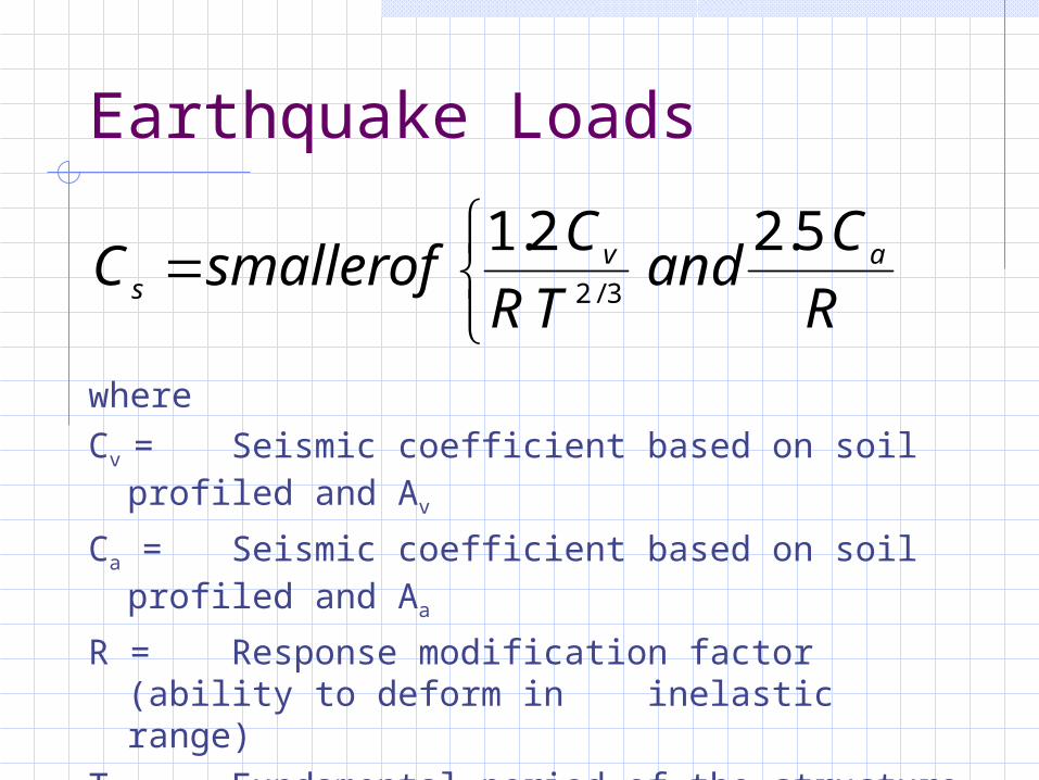
Earthquake Loads
whereCv = Seismic coefficient based on soil profiled
and Av
Ca = Seismic coefficient based on soil profiled and Aa
R = Response modification factor (ability to deform in inelastic range)
T = Fundamental period of the structure
R
Cand
TR
CofsmallerC av
s
5.22.13/2
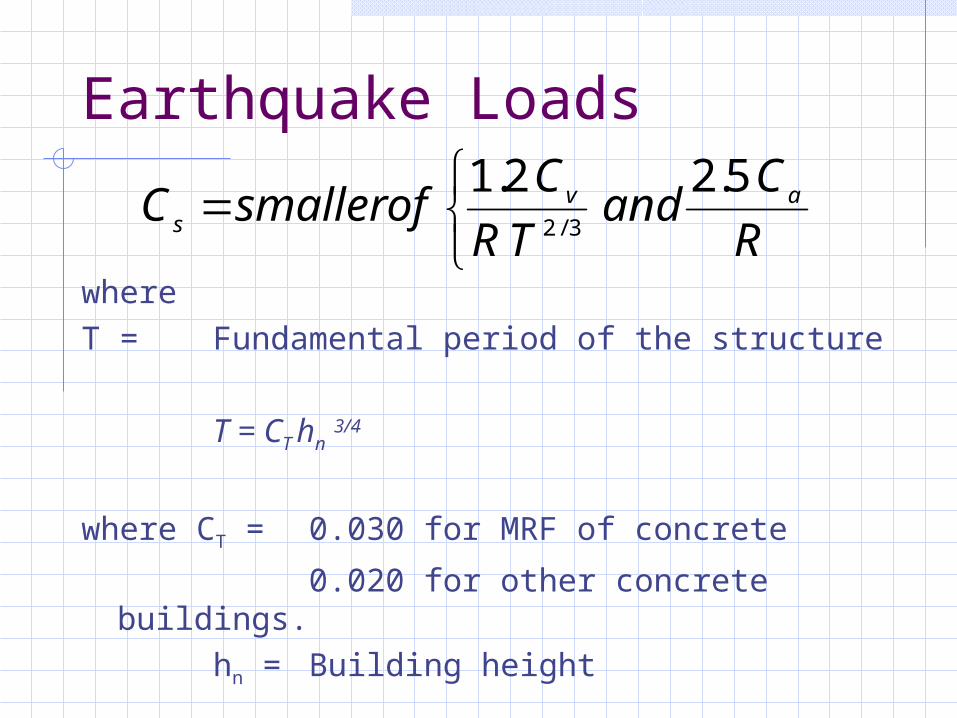
Earthquake Loads
whereT = Fundamental period of the structure
T = CT hn 3/4
where CT = 0.030 for MRF of concrete
0.020 for other concrete buildings.hn = Building height
R
Cand
TR
CofsmallerC av
s
5.22.13/2

Roof LoadsRoof Loads
Ponding of rainwater Roof must be able to support all rainwater that
could accumulate in an area if primary drains were blocked.
Ponding Failure:
Rain water ponds in area of maximum deflection
increases deflection allows more accumulation of water
cycle continues… potential failure

Roof LoadsRoof LoadsRoof loads are in addition to snow loads
Minimum loads for workers and construction materials during erection and repair

Construction LoadsConstruction Loads
Construction materials
Weight of formwork supporting weight of fresh concrete

wP1 P2 P3
C
T
jd
cm
tm
))a) Flexural stresses on a cross sectiona) Flexural stresses on a cross section
)b) Internal coupleInternal couple..
Basic Design Relationship:Basic Design Relationship:

The beam shown in the figure will safely support the load if, at every section, the resistance of the member exceed the The beam shown in the figure will safely support the load if, at every section, the resistance of the member exceed the effects of loadseffects of loads::
R S (2-1)The resistance, R is function of material and geometric properties.
To allow for variability in computed resistance and load effects, eq. (2-1) is rewritten as:
Rn 1S1+2S2+ … (2-1a)
is strength-reduction factor less than1I is load factor greater than 1Rn stands for nominal resistance (based on specified material and geometric properties.)S stands for load effects (based on specified loads.)
In terms of Moments: Mn DMD+LML+ … (2-2a)
Similar equations can be written for shear, Similar equations can be written for shear, VV, and axial forces, , and axial forces, PP::Vn DVD+LVL+ ... (2-2b)
Pn DPD+LPL+ … (2-2c)
Equation (2-1) is the basic limit-states design equation. Equations (2-2a) to (2-2c) are special forms.Equation (2-1) is the basic limit-states design equation. Equations (2-2a) to (2-2c) are special forms.
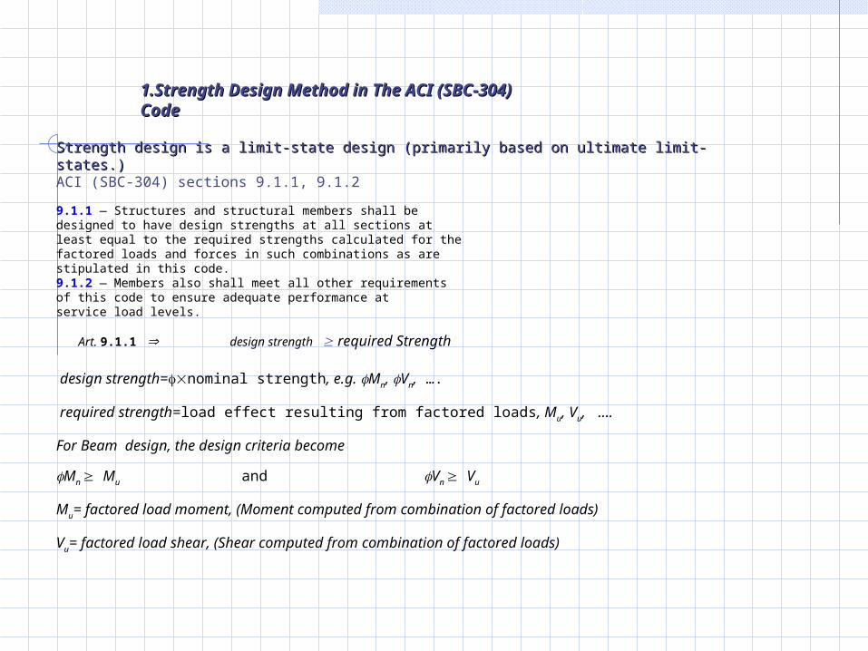
Strength design is a limit-state design (primarily based on ultimate limit-states.)Strength design is a limit-state design (primarily based on ultimate limit-states.)ACI (SBC-304) sections 9.1.1, 9.1.2
9.1.1 — Structures and structural members shall bedesigned to have design strengths at all sections atleast equal to the required strengths calculated for thefactored loads and forces in such combinations as arestipulated in this code. 9.1.2 — Members also shall meet all other requirementsof this code to ensure adequate performance atservice load levels.
Art. 9.1.1 design strength required Strength
design strength=nominal strength, e.g. Mn, Vn, ….
required strength=load effect resulting from factored loads, Mu, Vu, ….
For Beam design, the design criteria become
Mn Mu and Vn Vu
Mu= factored load moment, (Moment computed from combination of factored loads)
Vu= factored load shear, (Shear computed from combination of factored loads)
1.1.Strength Design Method in The ACI Strength Design Method in The ACI (SBC-304) Code(SBC-304) Code
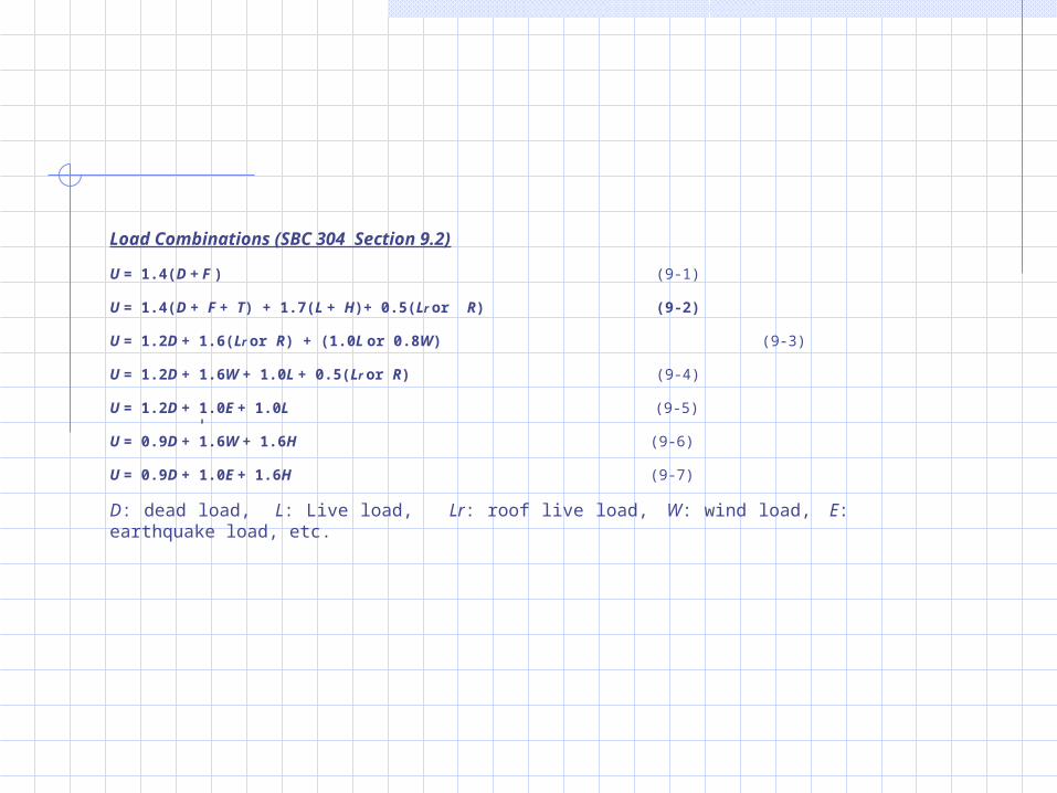
Load Combinations (SBC 304 Section 9.2)
U = 1.4(D + F ) )9-1)
U = 1.4(D + F + T) + 1.7(L + H)+ 0.5(Lr or R) (9-2)
U = 1.2D + 1.6(Lr or R) + (1.0L or 0.8W) )9-3)
U = 1.2D + 1.6W + 1.0L + 0.5(Lr or R) )9-4)
U = 1.2D + 1.0E + 1.0L )9-5)
U = 0.9D + 1.6W + 1.6H )9-6)
U = 0.9D + 1.0E + 1.6H )9-7)
D: dead load, L: Live load, Lr: roof live load, W: wind load, E: earthquake load, etc.

Strength Reduction Factors, (SBC 304 Section 9.3)
9.3.2.1 — Tension-controlled sections
as defined in SBC 304 Sec. 10.3.4 .......................................... 0.90
(See also SBC 304 Sec 9.3.2.7)
9.3.2.2 — Compression-controlled sections, as
defined in SBC 304 Sec 10.3.3:
(a)Members with spiral reinforcement
conforming to SBC 304 Sec 10.9.3.......................................... 0.70
(b) Other reinforced members ................................................. 0.65
9.3.2.2 — Shear and torsion .................................................... 0.75