lecture 2 sa
TRANSCRIPT

8/12/2019 Lecture 2 SA
http://slidepdf.com/reader/full/lecture-2-sa 1/14
Lecture 2 July 6, 2011
Hatley Pirbhai TemplateBy
Mangesh R. WanjariAsst. Professor, Department of CSE
RKNEC, Nagpur

8/12/2019 Lecture 2 SA
http://slidepdf.com/reader/full/lecture-2-sa 2/14
6/6/2014 2
Overview of the talk
Introduction to design method
according to Hatley and Pirbhai
Two types
overview of the requirements model
Further reading
References

8/12/2019 Lecture 2 SA
http://slidepdf.com/reader/full/lecture-2-sa 3/14
6/6/2014 3
Introduction
The requirements
model of the Hatley and
Pirbhai method is dividedinto two parts: A process
part and a control part
8/12/2019 Lecture 2 SA
http://slidepdf.com/reader/full/lecture-2-sa 4/14
6/6/2014 4
Introduction

8/12/2019 Lecture 2 SA
http://slidepdf.com/reader/full/lecture-2-sa 5/14
6/6/2014 5
Introduction
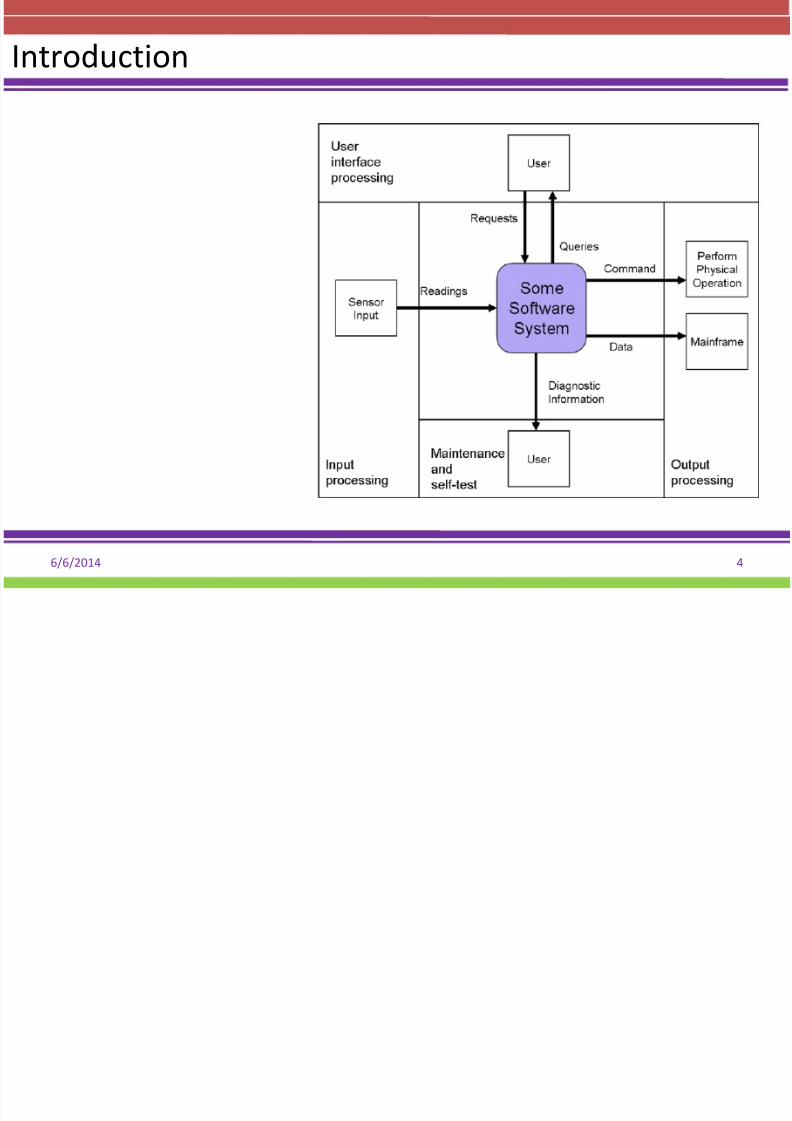
1. Hatley-Pirbhay modeling is an extension of the concept that every computersystem can be modeled through the usage of an input-processing-output model
by including the two additional features of user interface process and
maintenance/self testing.
2. These 5 components are added to a system model template to allow for
modeling of the system which allows for proper assignment to the processingregions.
3. The templates components are User Interface, Input, System Function and
Control, Output and Maintenance/Self Test.
4. This modeling technique allows for creation of a hierarchy of detail of which thetop level of this hierarchy should consist of a System Context Diagram.The
developed system context diagram serves the purpose of, "establish[ing] the
information boundary between the system being implemented and the
environment in which the system is to operate.”

8/12/2019 Lecture 2 SA
http://slidepdf.com/reader/full/lecture-2-sa 6/14
6/6/2014 6
THE REQUIREMENTS METHOD
1. This method merges into a unified whole the well-established
Structured Analysis (SA) method, and finite-state machine theory
2. Data processing is represented by conventional data flow diagrams
(DFDs), and the flow of control information is carried in a parallel
structure of control flow diagrams (CFDs).
3. Between these two are control specifications (CSPECs), containing the
finite state (FS) machine structures. These FS machines are used to
control the behavior of the processes in the DFDs, thus adding an
important dimension lacking in basic SA.
4. Input-to-output timing relationships are represented in a timing
specification (TSPEC), and all data and control information is defined in
a requirements dictionary.

8/12/2019 Lecture 2 SA
http://slidepdf.com/reader/full/lecture-2-sa 7/14
6/6/2014 7
1. This method models the physical realization of the system, and is anextension and formalization of the familiar engineering block
diagram.
2. Its principal graphical components are architecture flow diagrams
(AFDs) and architecture interconnect diagrams (AIDs).
3. The modules, flows, and channels are all rigorously defined in textualmodule and interconnect specifications, and in an architecture
dictionary.
4. The method includes an architecture template, which is used as a
guide in adding derived requirements to the requirements model,
and in allocating requirements to the architecture components.
5. The allocation of requirements to architecture is represented
graphically using Superbubbles on enhanced DFDs, and is further
recorded through Traceability Matrices.
THE ARCHITECTURE METHOD
8/12/2019 Lecture 2 SA
http://slidepdf.com/reader/full/lecture-2-sa 8/14
6/6/2014 8
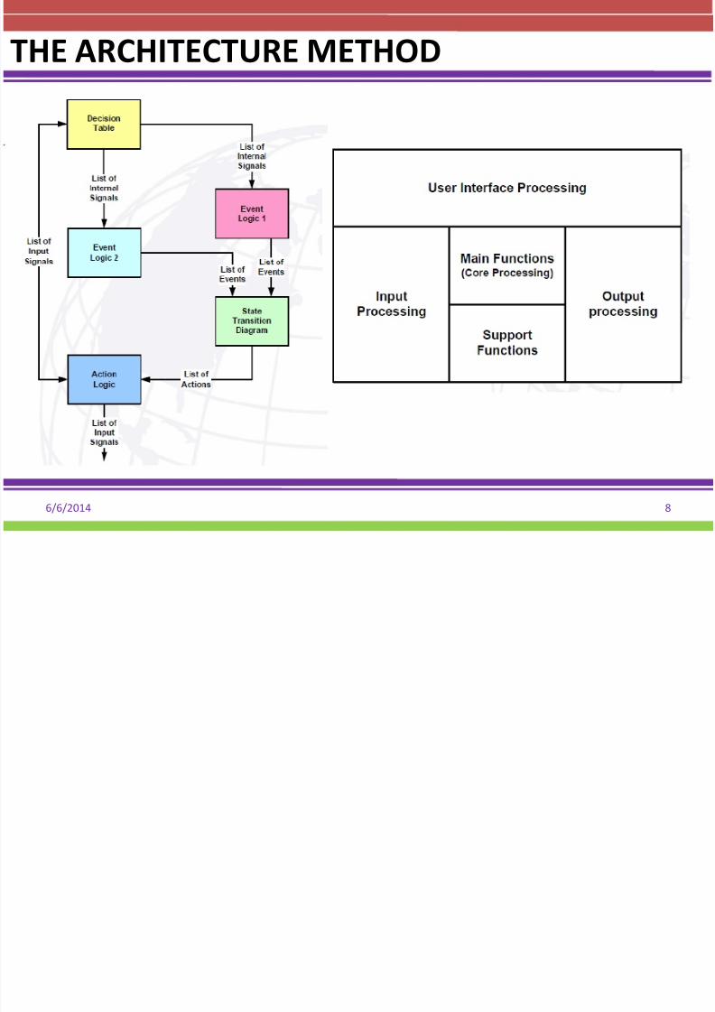
THE ARCHITECTURE METHOD

8/12/2019 Lecture 2 SA
http://slidepdf.com/reader/full/lecture-2-sa 9/14
6/6/2014 9
THE ARCHITECTURE METHOD

8/12/2019 Lecture 2 SA
http://slidepdf.com/reader/full/lecture-2-sa 10/14
6/6/2014 10
THE ARCHITECTURE METHOD
The
Steps

8/12/2019 Lecture 2 SA
http://slidepdf.com/reader/full/lecture-2-sa 11/14
6/6/2014 11
THE ARCHITECTURE METHOD
8/12/2019 Lecture 2 SA
http://slidepdf.com/reader/full/lecture-2-sa 12/14
6/6/2014 12
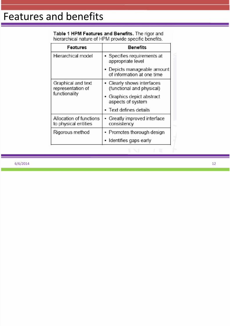
Features and benefits

8/12/2019 Lecture 2 SA
http://slidepdf.com/reader/full/lecture-2-sa 13/14
6/6/2014 13
Features and benefits
• Another advantage of a simulation-
based approach using H-P can be seen
by reference to the figure.
• As system development proceeds
down the left side of the “Vee” the
models developed provide the
foundation and guidance for the steps
as integration proceeds up the right side
of the “Vee”.
• It should noted that the “Vee” model
has been demonstrated to be consistent
with spiral development

8/12/2019 Lecture 2 SA
http://slidepdf.com/reader/full/lecture-2-sa 14/14
6/6/2014 14
Questions???
Thanks for Patient Listening…!!!