lecture 20: devices and i/o - · · 2014-06-24lecture 20: devices and i/o ... interrupt-request...
TRANSCRIPT

Lecture 20: Devices and I/O Computer Architecture and
Systems Programming (252-0061-00)
Timothy Roscoe
Herbstsemester 2012
© Systems Group | Department of Computer Science | ETH Zürich

Last time: P6 (ia32) Address Translation
CPU
VPN VPO 20 12
TLBT TLBI 4 16
virtual address (VA)
...
TLB (16 sets, 4 entries/set) VPN1 VPN2
10 10
PDE PTE
PDBR
PPN PPO 20 12
Page tables
TLB miss
TLB hit
physical address (PA)
result 32
...
CT CO 20 5
CI 7
L2 and DRAM
L1 (128 sets, 4 lines/set)
L1 hit
L1 miss

PTE VPN
Last time: VAX translation
Addr VPN Addr VPO
21 9
0 x
Addr VPN 0 0 PxTB 1 0
PTE VPO PTE VPN 1 0
0 0 SPTB 1 0
PTE VPO PTE PFN 1 0
Load
Addr PFO Addr PFN 1 0
Load
Load
← Virtual address requested (in seg. Px: user space)
← Virtual address of PTE (in seg. S0: system space)
← Physical address of PTE mapping the PTE we want
← Physical address of PTE we want
← The PTE: physical address of value we want
← Memory value (at last!) Data

Las time: Large Pages
• 4MB on 32-bit, 2MB on 64-bit
• Simplify address translation
• Useful for programs with very large, contiguous working sets – Reduces compulsory TLB misses
• How to use (Linux) – hugetlbfs support (since at least 2.6.16) – Use libhugetlbs
• {m,c,re}alloc replacements
VPN VPO
20 12
PPN PPO
20 12
VPN VPO
10 22
PPN PPO
10 22
versus

Last time: VM Buffering
• One iteration of a matrix-matrix multiply:
• Consequence – Each row is on different page – More rows than TLB entries: TLB thrashing – Solution: buffering = copy block to contiguous memory
• O(B2) cost for O(B3) operations
a b
* c
= c
+
assume > 4 KB = 512 doubles
blocksize B = 150
each row used O(B) times but every time O(B2) ops between

Today: I/O Devices
• What is a device?
• Registers
– Example: NS16550 UART
• Interrupts
• Direct Memory Access (DMA)
• PCI (Peripheral Component Interconnect)
• Summary

What is a device?
Specifically, to an OS programmer:
• Piece of hardware visible from software
• Occupies some location on a bus
• Set of registers
– Memory mapped or I/O space
• Source of interrupts
• May initiate Direct Memory Access transfers

Today: I/O Devices
• What is a device?
• Registers
– Example: NS16550 UART
• Interrupts
• Direct Memory Access (DMA)
• PCI (Peripheral Component Interconnect)
• Summary

Registers
• CPU can load from device registers:
– Obtain status info
– Read input data
• CPU can store to device registers:
– Set device state and configuration
– Write output data
– Reset states

Example: National Semiconductor ns16550 UART
• Universal Asynchronous Receiver/Transmitter – RS-232 serial line
• Basic IBM PC serial port – Chip now integrated into
Southbridge on all PCs – Still used for PC servers – Rarely seen on laptops any
more • First device driver
typically written for a new OS…

Registers
• Details of registers given in chip “datasheets” or “data books”
• Information is rarely trusted by OS programmers
From the data sheet for the
ns16550 UART

Addressing registers
1. Memory mapped: – Registers appear as memory locations – Access using loads/stores (movb/movw/movl/movq)
2. “I/O instructions”: – Different (16 bit) address space for older I/O devices – Specific (these days) to x86 architecture – Special instructions: inb, outb, etc.
3. Indirection: – Write an “index” register with an offset, then a “data” register
with the actual register value – Used to save scarce address space (usually I/O space)
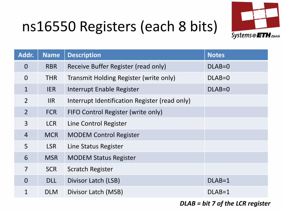
ns16550 Registers (each 8 bits)
Addr. Name Description Notes
0 RBR Receive Buffer Register (read only) DLAB=0
0 THR Transmit Holding Register (write only) DLAB=0
1 IER Interrupt Enable Register DLAB=0
2 IIR Interrupt Identification Register (read only)
2 FCR FIFO Control Register (write only)
3 LCR Line Control Register
4 MCR MODEM Control Register
5 LSR Line Status Register
6 MSR MODEM Status Register
7 SCR Scratch Register
0 DLL Divisor Latch (LSB) DLAB=1
1 DLM Divisor Latch (MSB) DLAB=1
DLAB = bit 7 of the LCR register

ns16550 LSR: Line Status Register
DR OE PE FE BI THRE TEMT ERRF
0 7
Error in Receiver FIFO
Transmitter Empty
Transmit Holding Register Empty
Break Interrupt
Framing Error
Parity Error
Overrun Error
Data Ready

Very simple UART driver #define UART_BASE 0x3f8 #define UART_THR (UART_BASE + 0) #define UART_RBR (UART_BASE + 0) #define UART_LSR (UART_BASE + 5) void serial_putc(char c) { // Wait until FIFO can hold more chars while( (inb(UART_LSR) & 0x20)== 0); // Write character to FIFO outb(UART_THR, c); } char serial_getc() { // Wait until there is a char to read while( (inb(UART_LSR) & 0x01) == 0); // Read from the receive FIFO return inb(UART_RBR); }
Register addresses from data sheet
0x3f8: location on a PC
Send a character (wait until we can first)
Read a character (spin waiting until one is
there to read)

Very simple UART driver
• Actually, far too simple! – But this is how the first version always looks…
• No initialization code, no error handling. • Uses Programmed I/O (PIO)
– CPU explicitly reads and writes all values to and from registers – All data must pass through CPU registers
• Uses polling – CPU polls device register waiting before send/receive
• Tight loop! – Can’t do anything else in the meantime
• Although could be extended with threads and care… – Without CPU polling, no I/O can occur

Registers are not memory
Device registers don’t behave like RAM!
• Register contents change without writes from CPU
– Status words
– Incoming data
• Writes to registers are used to trigger actions
– Sending data
– Resetting state machines

Dealing with caches
• Reads can’t come from the cache – Register value changes ⇒ cache becomes inconsistent
• Write-back caches (and write buffers) cause problems – You don’t know when the line will written
• Reads and writes cannot be combined into cache lines – Registers might require single word or byte writes only – Line-size writes stomp on other registers – Even spurious reads trigger device state changes
⇒ Device register access must bypass the cache – Handled in the MMU: PTEs have “no cache” flag – I/O space access isn’t cached anyway

Other challenges
1. How to avoid polling all the time?
– How does the CPU know when the device is ready, or finished?
2. How to avoid the CPU copying all the data?
– Can you transfer data without going through the CPU and caches?
– Can the CPU get on with something else?
3. Where do these register locations come from?
– How can the OS find devices in the physical address space?
– How are the physical addresses allocated?

Today: I/O Devices
• What is a device?
• Registers
– Example: NS16550 UART
• Interrupts
• Direct Memory Access (DMA)
• PCI (Peripheral Component Interconnect)
• Summary

Avoiding polling
• CPU can’t poll every device to see if it’s ready
– Waste of time
– Takes too long to react
• Solution: device can interrupt the processor
– Acts as an exception: saves state and jumps to kernel address
– Info about source encoded in the vector

Interrupts
• CPU Interrupt-request line triggered by I/O device – Might be edge- or level-triggered
• Interrupt handler receives interrupts
• Maskable to ignore or delay some interrupts
• Interrupt vector to dispatch interrupt to correct handler – Based on priority – Some nonmaskable
• Interrupt mechanism also used for exceptions

Recall x86 Exception Vectors 0 Divide error
1 Debug exception
2 Non-maskable interrupt (NMI)
3 Breakpoint
4 Overflow
5 Bounds check
6 Invalid opcode
7 Coprocessor not available
8 Double fault
9 Coprocessor segment overrun (386 or earlier)
A Invalid task state segment
B Segment not present
C Stack fault
D General protection fault
E Page Fault
F Reserved
10 Math fault
11 Alignment check
12 Machine check
13 SIMD floating point exception
14-1F Reserved to Intel
20-FF Available for external interrupts

Programmable Interrupt Controllers
x86 CPU
INTA
INTR
NMI
D0 … D7
Device 1
Device 2
Device n
… PIC
IRQ0
IRQ1
IRQ<n-1>

Today: I/O Devices
• What is a device?
• Registers
– Example: NS16550 UART
• Interrupts
• Direct Memory Access (DMA)
• PCI (Peripheral Component Interconnect)
• Summary

Direct Memory Access
• Avoid programmed I/O for lots of data
– E.g. fast network or disk interfaces
• Requires DMA controller
– Generally built-in these days
• Bypasses CPU to transfer data directly between I/O device and memory
– Doesn’t take up CPU time
– Can save memory bandwidth
– Only one interrupt per transfer

Old-style DMA transfer
CPU
Cache
Main memory Buffer
DMA/PCI controller
IDE disk controller
PCI bus
Frontside (memory) bus
1. Device driver requests data transfer of S bytes from disk controller; specifies buffer address A and size S to DMA controller
2. Disk controller starts DMA transfer of S bytes
3. Disk controller initiates bus request for each data byte from disk
4. DMA controller transfers byte to address A, increments A, decrements S.
5. When S == 0, DMA controller interrupts CPU to indicate transfer complete

Key DMA advantage
• Decoupling of data transfer from processing
– CPU does not need to copy data to/from device
– Doesn’t pollute CPU cache
– Can be processed when the CPU (or OS) decides
– Higher-performance: CPU and device work in parallel • Possible bus contention during transfers
• Possible disadvantages:
– Higher setup overhead for very small transfers
– Generally not a problem (even the UARTs do DMA!)

DMA and Caches
• DMA means memory becomes inconsistent with CPU caches
• Options:
1. CPU can map DMA buffers non-cacheable ⇒ large hit – probably wants to process data anyway
2. Cache can “snoop” DMAC bus transactions (but doesn’t scale beyond small SMP systems)
3. OS can explicitly flush/invalidate cache regions ⇒ cache management important part of device drivers!

DMA and Virtual Memory
• DMA addresses are physical – Appear on external bus
• User and OS code deal with virtual addresses (mostly)
• OS (and device drivers) must manually translate virtual ↔ physical addresses when programming DMA controllers – This can require more than just a hardware page table! – DMA of a single virtual address region might not be contiguous in
physical address space – Scatter-gather DMA controllers: DMA to/from a list of regions
• Very new systems: provide an IOMMU – Works like an MMU, but for DMA writes from devices – Must still be programmed by OS to match MMU state – Has all kinds of other interesting uses – beyond scope of this course!

Today: I/O Devices
• What is a device?
• Registers
– Example: NS16550 UART
• Interrupts
• Direct Memory Access (DMA)
• PCI (Peripheral Component Interconnect)
• Summary

Where are all the registers?
• How does the OS know which devices exist?
• Where are the device registers in the physical address space?
– And which interrupt vectors correspond to them?
• Solution: built into the I/O bus design
– Example: PCI

PCI is…
Peripheral Component Interconnect
• An electrical standard for connecting devices – As is PCMCIA, PCI-X, PCI-Express, etc.
• A standard for physical connectors
• A set of “bus protocols” for communication between devices
• A software-visible interface to I/O hardware
PCIe has succeeded PCI, but extends the same software-visible interface

PCI tries to solve many problems:
• Device discovery
– Finding out which devices are in the system
• Address allocation
– Which addresses should each device’s registers appear at?
• Interrupt routing
– Which interrupt signals from the device should map to which exception vectors?
• Intelligent DMA
– “Bus mastering” devices no longer need a DMA controller
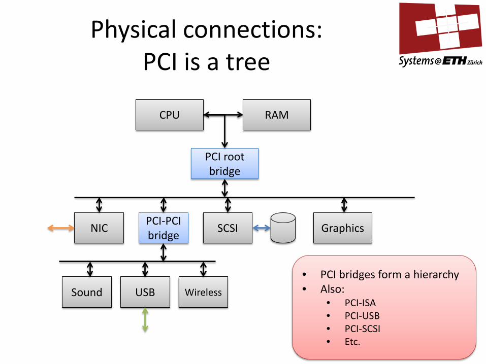
Physical connections: PCI is a tree
CPU RAM
PCI root bridge
USB
PCI-PCI bridge
SCSI Graphics
Sound
NIC
Wireless
• PCI bridges form a hierarchy • Also:
• PCI-ISA • PCI-USB • PCI-SCSI • Etc.

PCI address space is flat
• Each PCI device asks for a set of address ranges
– Physical address space (32-bit or 64-bit)
– I/O address space (usually 16-bit)
• Bridges up the tree remap addresses to the device
• Result:
– Each device appears as a set of contiguous address ranges • In memory space
• In I/O space (on x86 only)

PCI devices are self-describing
• Each device has a configuration header – Accessed through parent bridge, initially
• Some of the fields:
• Plus: – Allocated/required address ranges (BAR values) – Interrupts – Electrical information – Etc.
Bits Description
16 Manufacturer ID (idenfies Intel, 3Com, NVidia, etc.
16 Model ID (specific to manufacturer)
24 Class code (what kind of device is this?)
8 Version identifier

Finding all the devices
• Find the PCI “root complex” bridge – PCI bridge at the top of the tree – Large PCs can have more than one
• Read configuration to find all attached devices – Add to the list of devices and functions – Record requirements for address space – If a bridge, recurse!
• Result is: – List of all devices in system, with address space
requirements

Allocating addresses
• Find address ranges for each device and bridge Requirements include: – Each device has the size of address ranges it needs – All devices “below” a bridge have ranges that fit into the
bridge’s range – Each bridge has a range which includes all it’s “children”. – Each range is aligned to some power-of-2 boundary
• Then program: – Each PCI bridge with translation information – Each device with “base-address/range” (BAR) registers

PCI Interrupts
• Four interrupt lines – INTA, INTB, INTC, INTD… – Bridges allow arbitrary wiring of device lines to bridge lines – Translated by root bridge into system interrupt
• PCI Express introduces MSIs – Message-signalled interrupts – Interrupt encoded as PCI write to specified address range – Translated by root bridge into system interrupt – Interrupts can be individually steered to particular
cores/APICs

DMA over PCI
• PCI allows Bus Mastering
– Device can issue read/write transactions to anywhere in memory
– Even (in some cases) other PCI devices
• External DMA controllers no longer relevant
– Controller effectively integrated with device itself
– Principle applies: device DMAs data to/from memory
– Much more flexibility / intelligence possible

Today: I/O Devices
• What is a device?
• Registers
– Example: NS16550 UART
• Interrupts
• Direct Memory Access (DMA)
• PCI (Peripheral Component Interconnect)
• Summary

Intelligent devices
• Bus mastering, plus plenty of address space now
• Devices can now autonomously access any:
– Main memory
– Other devices
• Allows complex protocols for CPU↔Device interaction
– Try to keep both CPU and device busy during high load
– Extensive in-RAM buffering
– “Descriptor rings” exchange requests and responses

Example: Intel e1000 PCI-Express Ethernet card
• Multiple send queues • Multiple receive queues • Hashing of packet headers to queues • Directing interrupts to different cores • Packet checksumming in hardware • etc.

Summary
• Devices and the CPU communicate via:
– Memory mapped and I/O space registers
– Interrupts and interrupt vectors
– Direct Memory Access (DMA)
• I/O Interconnects (such as PCI):
– Allow devices to share/allocate physical addresses
– Allocate interrupts
– Permit bus mastering direct memory access