lecture 4: amplitude modulation (double sideband ...hawa.work/421/4 dsb-sc.pdf · called a...
TRANSCRIPT

9/8/2018
1
Lecture 4: Amplitude Modulation (Double Sideband Suppressed
Carrier, DSB-SC)
Dr. Mohammed HawaElectrical Engineering Department
University of Jordan
EE421: Communications I
Copyright © Dr. Mohammed Hawa Electrical Engineering Department, University of Jordan
Notation
2
9/8/2018
2
Copyright © Dr. Mohammed Hawa Electrical Engineering Department, University of Jordan
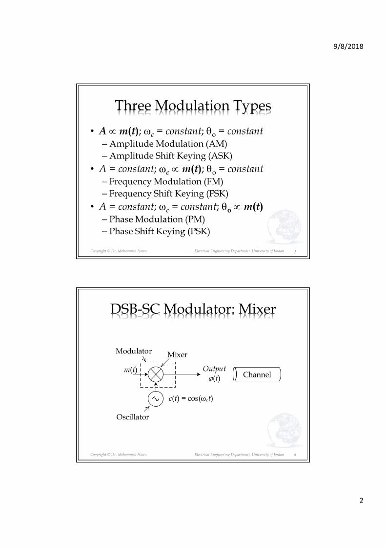
Three Modulation Types
• A ∝m(t); ωc = constant; θo = constant– Amplitude Modulation (AM)
– Amplitude Shift Keying (ASK)
• A = constant; ωc ∝m(t); θo = constant– Frequency Modulation (FM)
– Frequency Shift Keying (FSK)
• A = constant; ωc = constant; θo ∝m(t)– Phase Modulation (PM)
– Phase Shift Keying (PSK)
3
Copyright © Dr. Mohammed Hawa Electrical Engineering Department, University of Jordan
DSB-SC Modulator: Mixer
4
Output ϕ(t)
m(t)
Mixer
Channel
Oscillator
c(t) = cos(ωct)
Modulator
9/8/2018
3
Copyright © Dr. Mohammed Hawa Electrical Engineering Department, University of Jordan
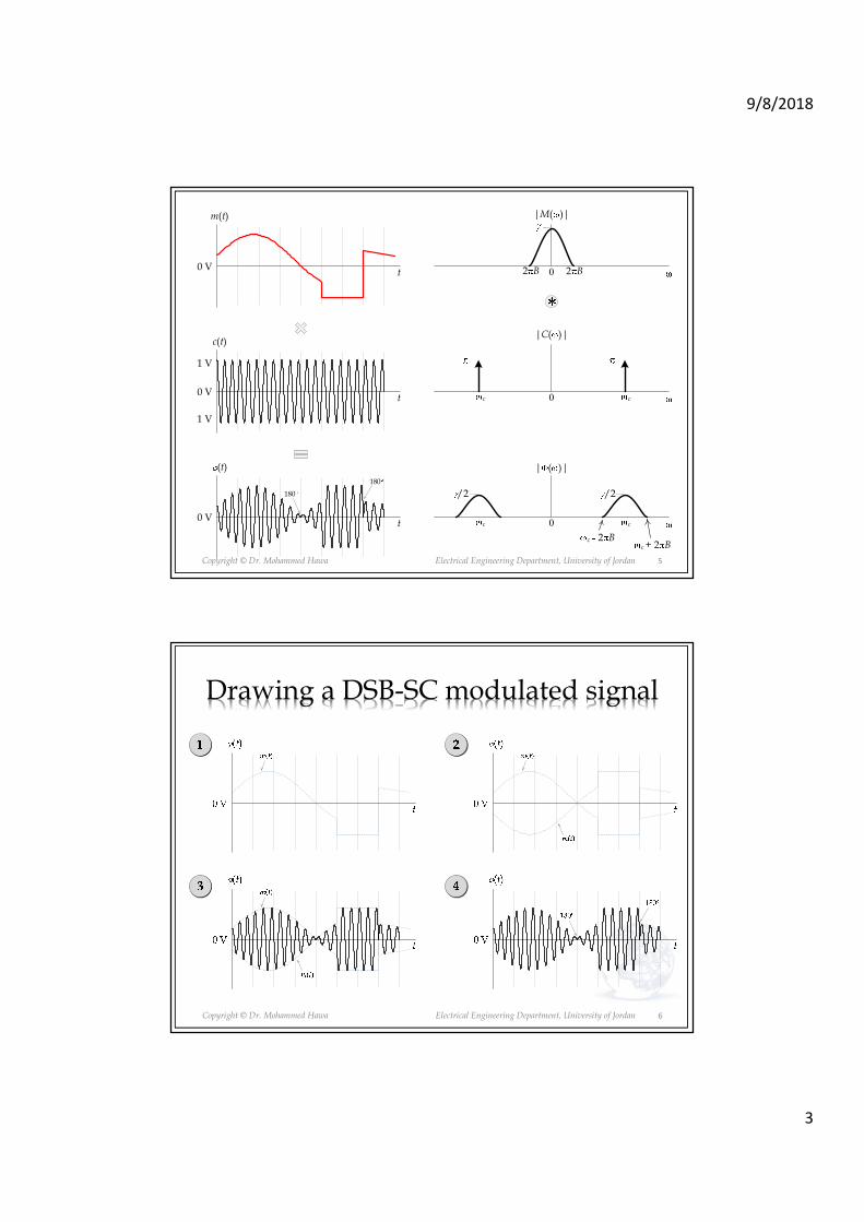
m(t)
t
0 V
0
|M( )|
2 B2 B
c(t)
t 0
|C( )|
cc
(t)
t
/2
0
/2
| ( )|
cc
0 V
0 V
180
180
c + 2 Bc 2 B
1 V
1 V
5
Copyright © Dr. Mohammed Hawa Electrical Engineering Department, University of Jordan
Drawing a DSB-SC modulated signal
6

9/8/2018
4
Copyright © Dr. Mohammed Hawa Electrical Engineering Department, University of Jordan
DSB-SC Demodulator: Mixer again!
7
Outputy(t)
ϕ(t)
Mixer
LPFH(ω)
Channelx(t)
c(t) = cos(ωct)
Demodulator
Copyright © Dr. Mohammed Hawa Electrical Engineering Department, University of Jordan 8

9/8/2018
5
Copyright © Dr. Mohammed Hawa Electrical Engineering Department, University of Jordan 9
Copyright © Dr. Mohammed Hawa Electrical Engineering Department, University of Jordan
The LPF is the missing piece!
Smoothed Output
0 V
x(t)
t
10
9/8/2018
6
Copyright © Dr. Mohammed Hawa Electrical Engineering Department, University of Jordan
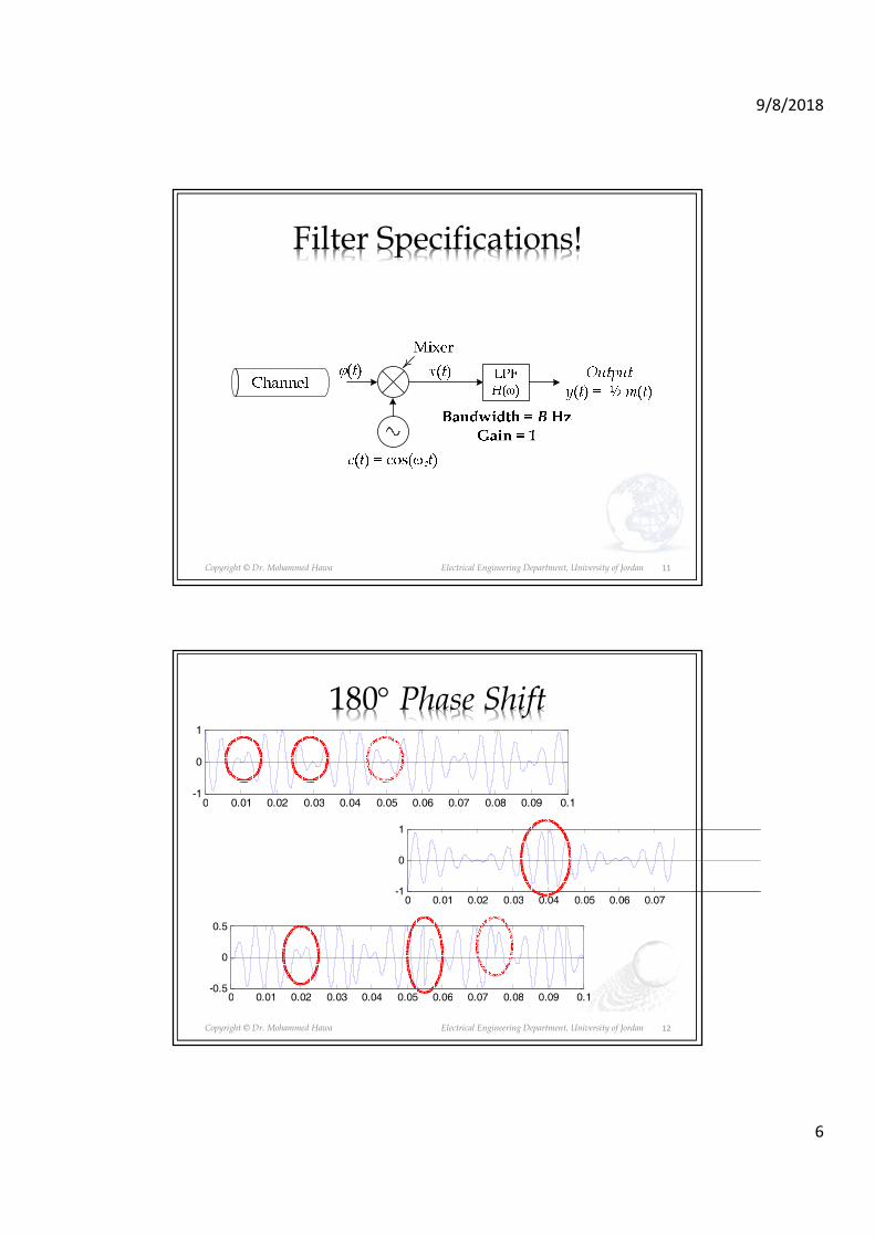
Filter Specifications!
11
Copyright © Dr. Mohammed Hawa Electrical Engineering Department, University of Jordan
180° Phase Shift
0 0.01 0.02 0.03 0.04 0.05 0.06 0.07 0.08 0.09 0.1-0.5
0
0.5
m
0 0.01 0.02 0.03 0.04 0.05 0.06 0.07-1
0
1
0 0.01 0.02 0.03 0.04 0.05 0.06 0.07 0.08 0.09 0.1-1
0
1
12

9/8/2018
7
Copyright © Dr. Mohammed Hawa Electrical Engineering Department, University of Jordan
Example
• Assume we perform DSB-SC modulation for the baseband signal m(t) = α cos (ωm t) [the case of tone modulation], where ωc >> ωm:– Sketch the time-domain modulated signal ϕ(t).
– Sketch the Fourier transform of the modulated signal Φ(ω) [frequency domain].
– Find the bandwidth of m(t) and ϕ(t).
– Find the average power in both m(t) and ϕ(t).
– Show the demodulator hardware.
– Sketch ���� and ���� in the demodulator.
13
Copyright © Dr. Mohammed Hawa Electrical Engineering Department, University of Jordan
Solution
14
9/8/2018
8
Copyright © Dr. Mohammed Hawa Electrical Engineering Department, University of Jordan
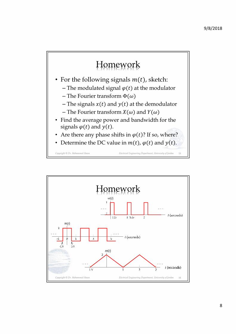
Homework
• For the following signals ����, sketch:
– The modulated signal ���� at the modulator
– The Fourier transform Φ��
– The signals ���� and � � at the demodulator
– The Fourier transform �� and ���
• Find the average power and bandwidth for the signals ���� and � � .
• Are there any phase shifts in � � ? If so, where?
• Determine the DC value in ����, ���� and � � .
15
Copyright © Dr. Mohammed Hawa Electrical Engineering Department, University of Jordan
Homework
16

9/8/2018
9
Copyright © Dr. Mohammed Hawa Electrical Engineering Department, University of Jordan
Solution: Part(b)
17
ω
|M(ω)|
ω0
|Φ(ω)|
ωc−ωc ωc + 2ω0ωc − 2ω0
−1
2
m(t)
t (sec)31 50 0 ω0−ω0 2ω0 3ω0−3ω0
2π|α1|2π|α-1|
2π|α2|2π|α-2|2π|α3|2π|α-3|
−2
2
ϕ(t)
t (sec)31 50
2π|α1|/22π|α-1|/22π|α1|/22π|α-1|/2180°
0.5−0.5
180° 180°
1
Copyright © Dr. Mohammed Hawa Electrical Engineering Department, University of Jordan
Homework
• For the following circuit, sketch���� and � � , along with the Fourier transform �� and ���.
18

9/8/2018
10
Copyright © Dr. Mohammed Hawa Electrical Engineering Department, University of Jordan
How to build a Mixer?
• Variable Gain Amplifier
– The basic design.
• Gilbert Cell (e.g., MC 1496)
– Popular (used in Integrated Circuits).
– Uses variable gain differential amplifiers.
• Switching Modulator
– Uses diodes.
– Cheaper design (was popular before ICs).
19
Copyright © Dr. Mohammed Hawa Electrical Engineering Department, University of Jordan
Variable Gain Amplifier
G
Fixed Gain
m(t) G m(t)
G
Variable GainG = k c(t)
m(t) k c(t) m(t)
20

9/8/2018
11
Copyright © Dr. Mohammed Hawa Electrical Engineering Department, University of Jordan
Gilbert Cell inside Phones
21
Copyright © Dr. Mohammed Hawa Electrical Engineering Department, University of Jordan
LTE Modem
(CAT 4 up to 150Mbps)
22

9/8/2018
12
Copyright © Dr. Mohammed Hawa Electrical Engineering Department, University of Jordan 23
Copyright © Dr. Mohammed Hawa Electrical Engineering Department, University of Jordan
RF Solid State Circuits
24

9/8/2018
13
Copyright © Dr. Mohammed Hawa Electrical Engineering Department, University of Jordan 25
Copyright © Dr. Mohammed Hawa Electrical Engineering Department, University of Jordan
Gilbert Cell (MC1496) Schematic
26
9/8/2018
14
Copyright © Dr. Mohammed Hawa Electrical Engineering Department, University of Jordan
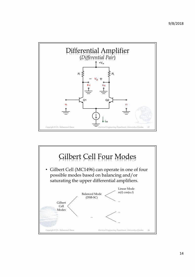
Differential Amplifier (Differential Pair)
27
Copyright © Dr. Mohammed Hawa Electrical Engineering Department, University of Jordan
Gilbert Cell Four Modes
• Gilbert Cell (MC1496) can operate in one of four possible modes based on balancing and/or saturating the upper differential amplifiers.
28
Gilbert Cell
Modes
Balanced Mode(DSB-SC)
...
Linear Modem(t) cos(ωct)
...
...
...

9/8/2018
15
Copyright © Dr. Mohammed Hawa Electrical Engineering Department, University of Jordan
Switching Modulator
29
Copyright © Dr. Mohammed Hawa Electrical Engineering Department, University of Jordan
DSB-SC Switching Modulator (Series-bridge diode modulator)
Channel
Oscillator
m(t)
Band-pass FilterGain = 1
Bandwidth = 2B HzCenter Frequency = c
y(t)
C cos( ct)
x(t)
D1 D2
D3 D4
30

9/8/2018
16
Copyright © Dr. Mohammed Hawa Electrical Engineering Department, University of Jordan 31
Copyright © Dr. Mohammed Hawa Electrical Engineering Department, University of Jordan
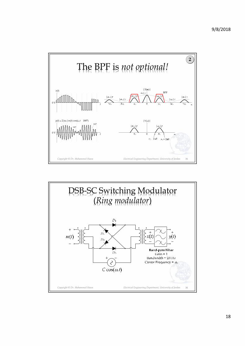
The BPF is not optional!
0 V
y(t) 2| 1|m(t) cos( ct)
t
180
180
0
|Y( )|
c + 2 Bc 2 B
x(t)
t0 V
0
|X( )|
cc cc cc
BPF0|| 1|| -1|
| 2|| -2|| 3|| -3|
cc
| 1|| -1|
32

9/8/2018
17
Copyright © Dr. Mohammed Hawa Electrical Engineering Department, University of Jordan
DSB-SC Switching Modulator (Shunt-bridge diode modulator)
33
Copyright © Dr. Mohammed Hawa Electrical Engineering Department, University of Jordan 34
9/8/2018
18
Copyright © Dr. Mohammed Hawa Electrical Engineering Department, University of Jordan
The BPF is not optional!
0 V
y(t) 2| 1|m(t) cos( ct 180 )
t
180
180
0
|Y( )|
c + 2 Bc 2 B
x(t)
t0 V
0
|X( )|
cc cc cc
BPF0|| 1|| -1|
| 2|| -2|| 3|| -3|
cc
| 1|| -1|
35
Copyright © Dr. Mohammed Hawa Electrical Engineering Department, University of Jordan
DSB-SC Switching Modulator (Ring modulator)
36

9/8/2018
19
Copyright © Dr. Mohammed Hawa Electrical Engineering Department, University of Jordan 37
Copyright © Dr. Mohammed Hawa Electrical Engineering Department, University of Jordan
The BPF is not optional!
0 V
y(t) 2| 1|m(t) cos( ct)
t
180
180
0
|Y( )|
c + 2 Bc 2 B
x(t)
t0 V
0
|X( )|
cc cc cc
BPF
| 1|| -1| | 3|| -3|
cc
| 1|| -1|
38
9/8/2018
20
Copyright © Dr. Mohammed Hawa Electrical Engineering Department, University of Jordan
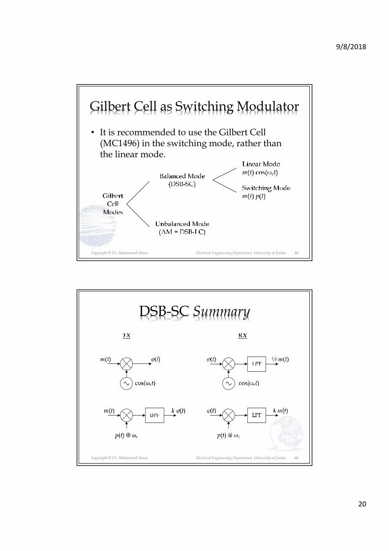
Gilbert Cell as Switching Modulator
• It is recommended to use the Gilbert Cell (MC1496) in the switching mode, rather than the linear mode.
39
Copyright © Dr. Mohammed Hawa Electrical Engineering Department, University of Jordan
DSB-SC Summary
40
9/8/2018
21
Copyright © Dr. Mohammed Hawa Electrical Engineering Department, University of Jordan
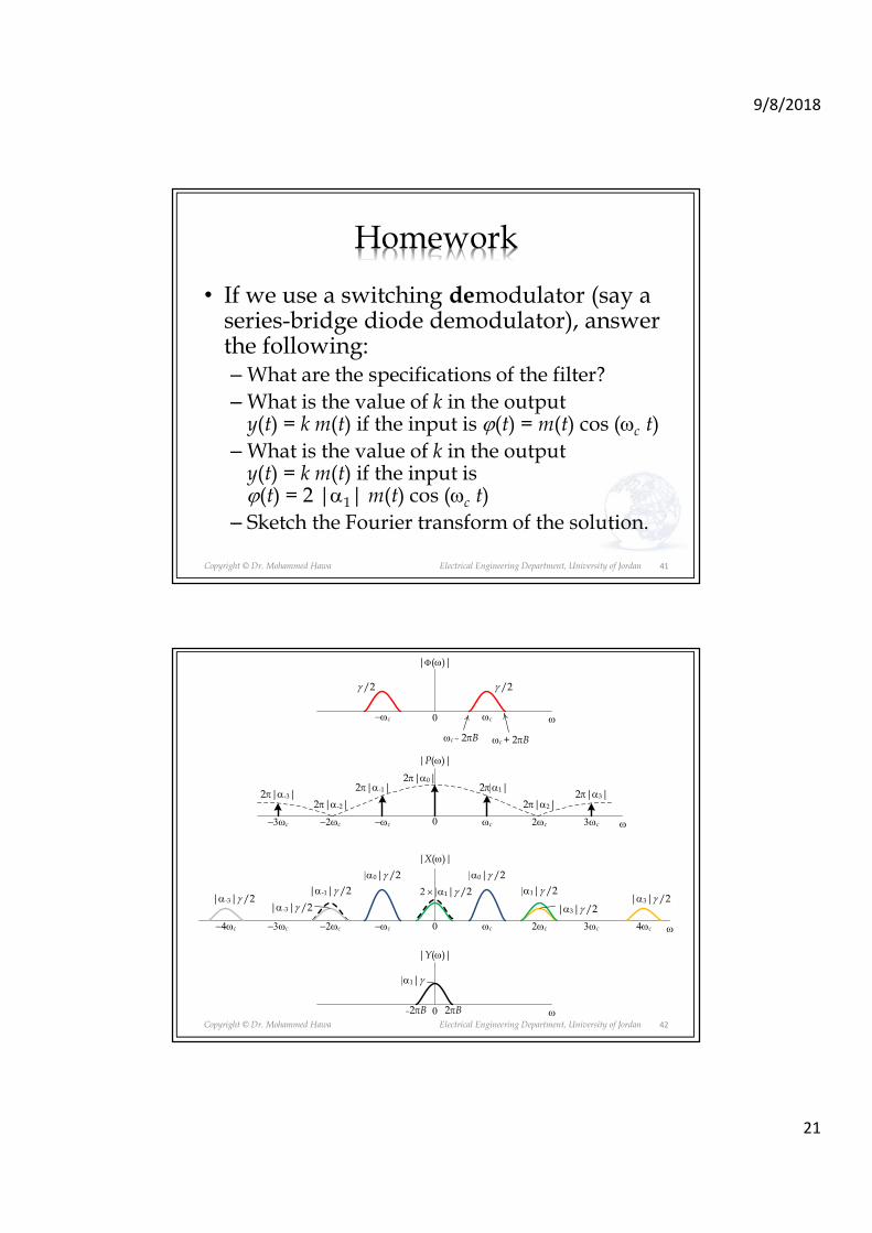
Homework
• If we use a switching demodulator (say a series-bridge diode demodulator), answer the following:–What are the specifications of the filter?
–What is the value of k in the output y(t) = k m(t) if the input is ϕ(t) = m(t) cos (ωc t)
–What is the value of k in the output y(t) = k m(t) if the input is ϕ(t) = 2 |α1| m(t) cos (ωc t)
– Sketch the Fourier transform of the solution.
41
Copyright © Dr. Mohammed Hawa Electrical Engineering Department, University of Jordan 42
ω0
|α1|γ
|Y(ω)|
2πB−2πB
ω0
|P(ω)|
ωc−ωc
ω0
|Φ(ω)|
ωc + 2πBωc − 2πB
2ωc−2ωc 3ωc−3ωc
2π|α0|2π|α1|2π|α-1|
2π|α2|2π|α-2|2π|α3|2π|α-3|
ω0
|X(ω)|
ωc−ωc 2ωc−2ωc 3ωc−3ωc
|α0|γ /2|α0|γ /2
|α3|γ /2
ωc−ωc
γ /2γ /2
|α3|γ /2|α-3|γ /2
|α1|γ /22 × |α1|γ /2|α-1|γ /2
4ωc−4ωc
|α-3|γ /2
9/8/2018
22
Copyright © Dr. Mohammed Hawa Electrical Engineering Department, University of Jordan
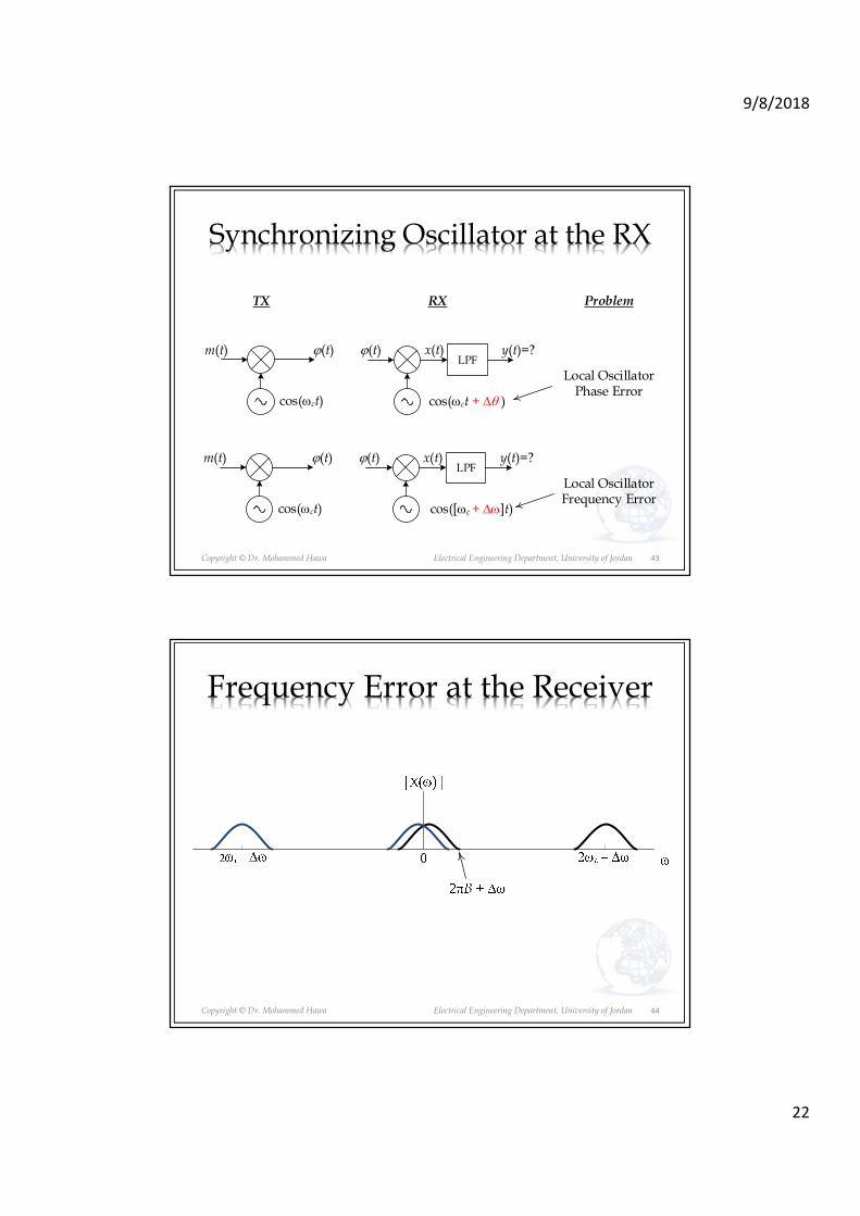
Synchronizing Oscillator at the RX
43
y(t)=?ϕ(t)LPF
ϕ(t)m(t)
cos(ωct) cos(ωct + ∆θ )
TX RX
y(t)=?ϕ(t)LPF
ϕ(t)m(t)
cos(ωct) cos([ωc + ∆ω]t)
Problem
Local Oscillator Phase Error
Local Oscillator Frequency Error
x(t)
x(t)
Copyright © Dr. Mohammed Hawa Electrical Engineering Department, University of Jordan
Frequency Error at the Receiver
44
9/8/2018
23
Copyright © Dr. Mohammed Hawa Electrical Engineering Department, University of Jordan 45
To avoid problems due to phase and frequency errors
• Solution #1: Use a PLL (Phase-Locked Loop) at the RX. A PLL can, by observing � � , recover the exact frequency and phase of the carrier at the TX, and hence use these values at the RX. The PLL is called a carrier-recovery circuit (complex and expensive). The receiver in this case is known as a synchronous or coherent receiver.
• Solution #2: Do not generate a carrier at the RX. Rather, let the TX send an extra copy of the carrier (e.g., DSB-LC) to help the RX demodulate � � . The RX is known as asynchronous or incoherentreceiver (cheaper), but the TX is power inefficient.