lecture 4. analog communications part ii. frequency ...lindai/3008_lecture4_fm.pdf1 lecture 4....
TRANSCRIPT

1
Lecture 4. Analog Communications
Part II. Frequency Modulation (FM)
• Angle Modulation (FM and PM)
• Spectral Characteristics of FM signals
• FM Modulator and Demodulator Lin Dai (City University of Hong Kong) EE3008 Principles of Communications Lecture 4
2
More About Amplitude Modulation
• Simple
• High requirement on amplifiers
– Linear amplifiers are difficult to achieve in applications.
• Low fidelity performance
– Noise enhancement in quiet periods
– No tradeoff between bandwidth and fidelity performance
and bandwidth efficient (compared to FM)
Lin Dai (City University of Hong Kong) EE3008 Principles of Communications Lecture 4

3
Angle Modulation
1 ( )( )
2
d tf t
dt
( ) cos( ( ))AnMs t A t
An angle-modulated signal can be written as
: Instantaneous Phase
: Instantaneous Frequency
( )t
( )f t
A typical carrier signal: ( ) 2 ( ),ct f t t
• Phase Modulation (PM):
( ) ( )t s t ( ) cos(2 ( ))PM cs t A f t s t
• Frequency Modulation (FM):
1 ( )( )
2
d tks t
dt
( ) cos(2 ( ( ) ))
t
FM cs t A f t k s d
Lin Dai (City University of Hong Kong) EE3008 Principles of Communications Lecture 4
1 ( )( )
2c
d tf t f
dt
4
Phase Deviation and Frequency Deviation
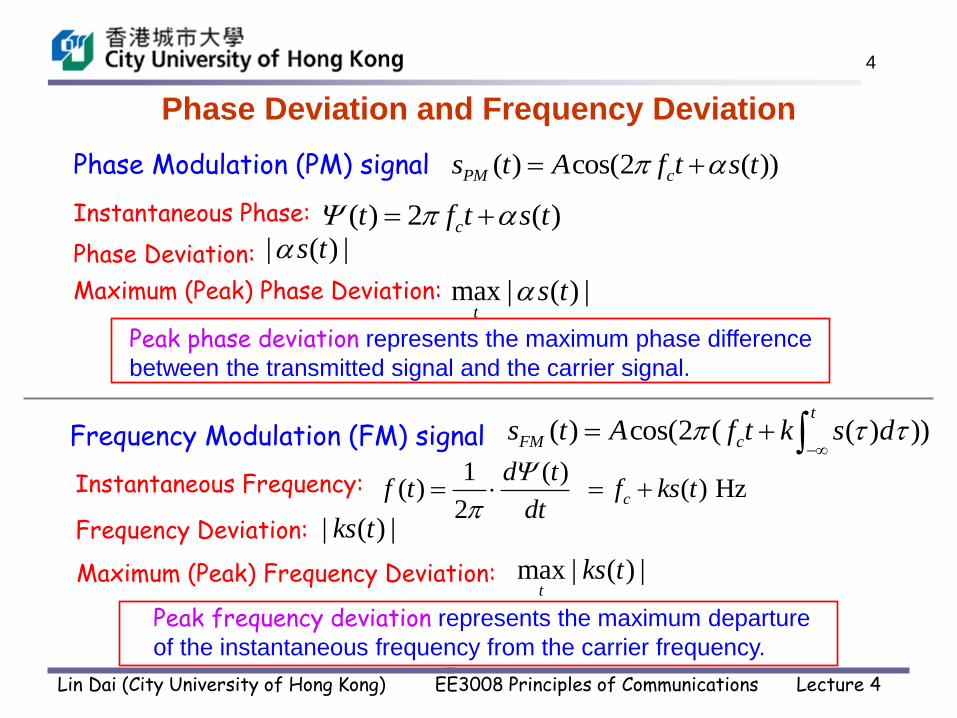
Phase Modulation (PM) signal
Frequency Modulation (FM) signal
( ) cos(2 ( ))PM cs t A f t s t
( ) cos(2 ( ( ) ))t
FM cs t A f t k s d
( ) 2 ( )ct f t s t
Instantaneous Frequency:
max | ( ) |t
ks t
Instantaneous Phase:
max | ( ) |t
s tMaximum (Peak) Phase Deviation:
Maximum (Peak) Frequency Deviation:
1 ( )( ) ( ) Hz
2c
d tf t f ks t
dt
Peak phase deviation represents the maximum phase difference
between the transmitted signal and the carrier signal.
Peak frequency deviation represents the maximum departure
of the instantaneous frequency from the carrier frequency.
Lin Dai (City University of Hong Kong) EE3008 Principles of Communications Lecture 4
Phase Deviation: | ( ) |s t
Frequency Deviation: | ( ) |ks t
5
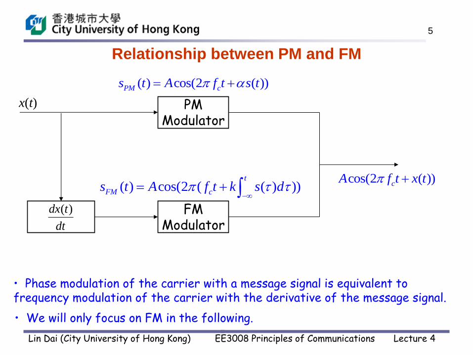
Relationship between PM and FM
( ) cos(2 ( ))PM cs t A f t s t
( ) cos(2 ( ( ) ))t
FM cs t A f t k s d
PM Modulator
x(t)
FM Modulator
• Phase modulation of the carrier with a message signal is equivalent to frequency modulation of the carrier with the derivative of the message signal.
• We will only focus on FM in the following.
( )dx t
dt
cos(2 ( ))cA f t x t
Lin Dai (City University of Hong Kong) EE3008 Principles of Communications Lecture 4

6
FM Signal
sFM(t)
s(t)
Lin Dai (City University of Hong Kong) EE3008 Principles of Communications Lecture 4
7
Spectral Characteristics of Frequency
Modulated Signals
Lin Dai (City University of Hong Kong) EE3008 Principles of Communications Lecture 4
8
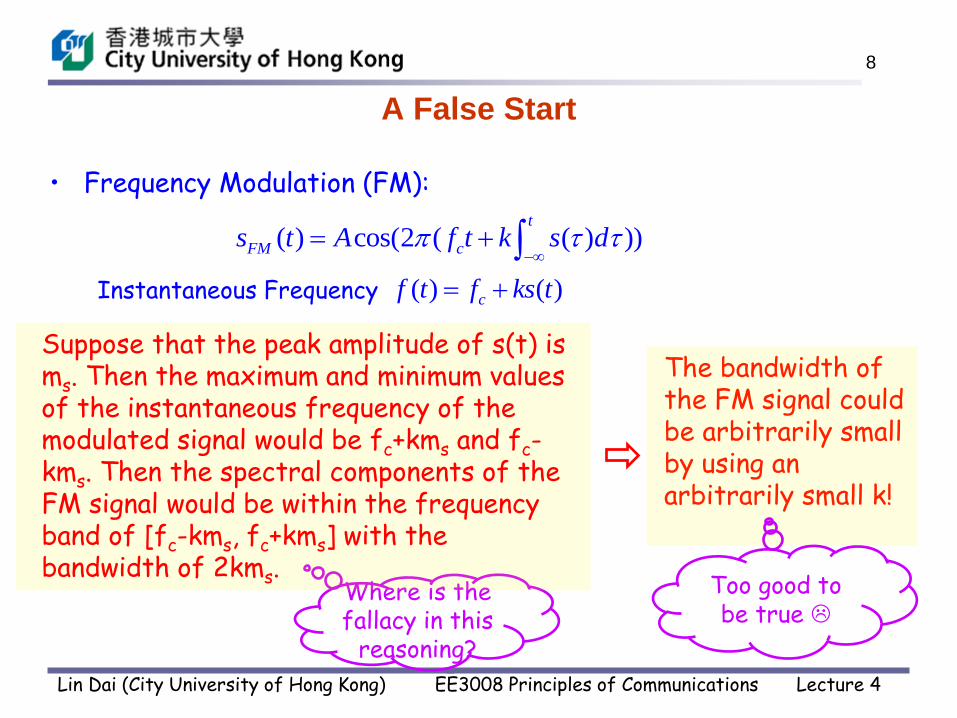
A False Start
• Frequency Modulation (FM):
( ) ( )cf t f ks t
( ) cos(2 ( ( ) ))t
FM cs t A f t k s d
Instantaneous Frequency
Where is the fallacy in this
reasoning?
The bandwidth of the FM signal could be arbitrarily small by using an arbitrarily small k!
Too good to be true
Lin Dai (City University of Hong Kong) EE3008 Principles of Communications Lecture 4
Suppose that the peak amplitude of s(t) is ms. Then the maximum and minimum values of the instantaneous frequency of the modulated signal would be fc+kms and fc-kms. Then the spectral components of the FM signal would be within the frequency band of [fc-kms, fc+kms] with the bandwidth of 2kms.

9
FM Sinusoidal Signal
= cos{2 [ sin(2 )]}2
mc m
m
kAA f t f t
f
Peak frequency deviation:
( ) cos(2 )c m mf t f kA f t
max | ( ) | mf ks t kA
Instantaneous phase
= cos[2 sin(2 )]c m
m
fA f t f t
f
Instantaneous frequency:
( ) cos{2 [ cos(2 ) ]}t
FM c m ms t A f t k A f d
( ) cos(2 )m ms t A f t
• Let us first assume the message signal s(t) is a sinusoidal signal:
• Peak frequency deviation is proportional to Am, the amplitude of the message signal s(t).
mf kA
m
f
f
• is defined as the modulation index.
= cos[2 sin(2 )]c mA f t f t
Lin Dai (City University of Hong Kong) EE3008 Principles of Communications Lecture 4

10
( ) cos[2 sin(2 )]FM c ms t A f t f t
= ( cos(2 ) 1)cos(2 )m cAc m f t f t
FM -- With a sinusoidal message signal : ( ) cos(2 )m ms t A f t
( ) ( ( ) )cos(2 )AM DSB C cs t A s t c f t ( ) ( )
( ) ( )
m m m
m m
A c A c Am
A c A c c
m
m
kA
f
With a general message signal s(t): max | ( ) |
s
k s t
B
AM-DSB-C -- with a message signal s(t): max[ ( ) ] min[ ( ) ]
max[ ( ) ] min[ ( ) ]
s t c s t cm
s t c s t c
With a sinusoidal message signal : ( ) cos(2 )m ms t A f t
Modulation Indices of AM-DSB-C and FM
Lin Dai (City University of Hong Kong) EE3008 Principles of Communications Lecture 4

11
sFM(t) can be expanded as an infinite Fourier series:
( ) cos[2 sin(2 )]
= ( )cos[2 ( ) ]
FM c m
n c m
n
s t A f t f t
A J f nf t
( sin )1( )
2
j x nx
nJ e dx
FM Sinusoidal Signal (Cont’d)
Jn() is called the Bessel Function of the first kind and of order n, which
is defined by
Read Reference [1] (Sec. 3.3.2) to see the derivation of sFM(t)
and more details about Bessel Function.
Lin Dai (City University of Hong Kong) EE3008 Principles of Communications Lecture 4

12
A Little Bit about Bessel Function
For small values of : ( )2 !
n
n nJ
n
For large values of : 2
( ) cos4 2
n
nJ
( ) even( )
( ) odd
n
n
n
J nJ
J n
Symmetry property: ( ) ( )n nJ J
Lin Dai (City University of Hong Kong) EE3008 Principles of Communications Lecture 4
13
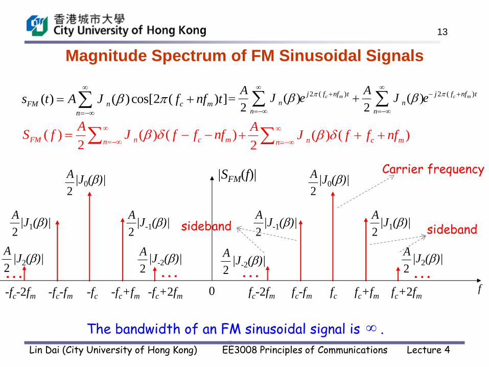
Magnitude Spectrum of FM Sinusoidal Signals
( ) ( )cos[2 ( ) ]FM n c m
n
s t A J f nf t
sideband
Carrier frequency
sideband
|J0()|
2
A
|J-1()| |J1()| 2
A
2
A
|J-2()| |J2()|
2
A
2
A
… … -fc -fc+fm -fc+2fm -fc-2fm -fc-fm fc fc+fm fc+2fm fc-2fm fc-fm
… … f
|SFM(f)|
0
|J0()|
2
A
|J1()| |J-1()| 2
A
2
A
|J2()| |J-2()| 2
A
2
A
( ) ( ) ( )2
FM n c mn
AS f J f f nf
2 ( ) 2 ( )( ) ( )
2 2c m c mj f nf t j f nf t
n n
n n
A AJ e J e
( ) ( )2
n c mn
AJ f f nf
The bandwidth of an FM sinusoidal signal is .
Lin Dai (City University of Hong Kong) EE3008 Principles of Communications Lecture 4

14
Power Spectrum of FM Sinusoidal Signals
|J0()|2 2
4
A
|J-1()|2 |J1()|2 2
4
A2
4
A
|J-2()|2 |J2()|2 2
4
A2
4
A
… … -fc -fc+fm -fc+2fm -fc-2fm -fc-fm fc fc+fm fc+2fm fc-2fm fc-fm
… … f
GFM(f)
0
|J0()|2 2
4
A
|J1()|2 |J-1()|2 2
4
A2
4
A
|J2()|2 |J-2()|2 2
4
A2
4
A
( ) ( ) ( )2
FM n c mn
AS f J f f nf
( ) ( )
2n c mn
AJ f f nf
2 22 2
( ) ( ) ( ) ( ) ( )4 4
FM n c m n c m
n n
A AG f J f f nf J f f nf
Lin Dai (City University of Hong Kong) EE3008 Principles of Communications Lecture 4

15
Power Spectrum of FM Sinusoidal Signals
Power at carrier
2
2t
AP
22
0 ( )2
AJ
( ) cos[2 sin(2 )]FM c ms t A f t f t
2
12 2
1( ) ( )
2n nn n
AJ J
Power at sidebands
|J0()|2 2
4
A
|J-1()|2 |J1()|2 2
4
A2
4
A
|J-2()|2 |J2()|2 2
4
A2
4
A
… … -fc -fc+fm -fc+2fm -fc-2fm -fc-fm fc fc+fm fc+2fm fc-2fm fc-fm
… … f
GFM(f)
0
|J0()|2 2
4
A
|J1()|2 |J-1()|2 2
4
A2
4
A
|J2()|2 |J-2()|2 2
4
A2
4
A
tP 2
2
A
2 2
0 1( ) 2 ( ) 1nn
J J
Lin Dai (City University of Hong Kong) EE3008 Principles of Communications Lecture 4
16
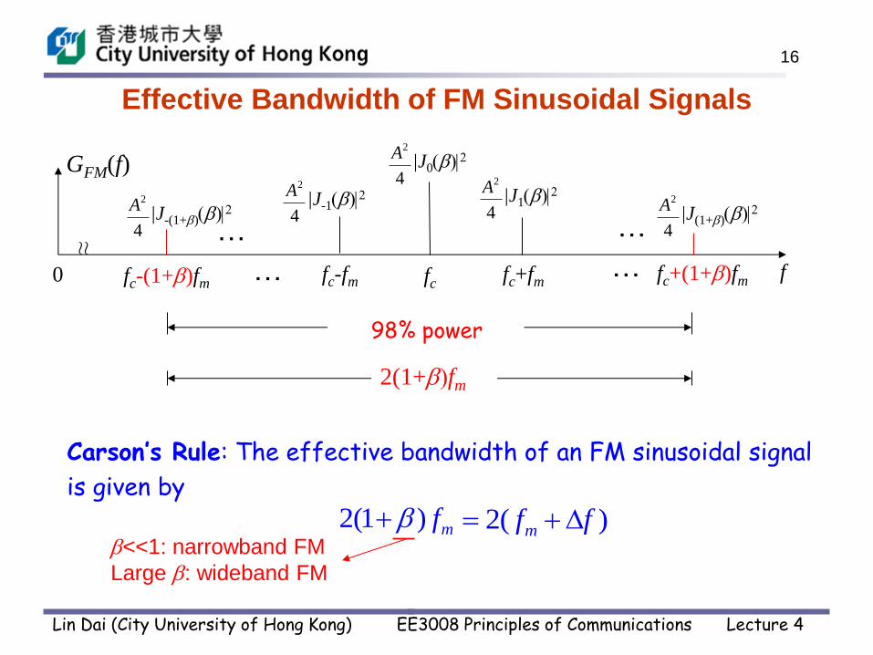
Effective Bandwidth of FM Sinusoidal Signals
|J(1+)|2
…
…
…
…
GFM(f)
≈
98% power
2(1+fm
Carson’s Rule: The effective bandwidth of an FM sinusoidal signal
is given by
<<1: narrowband FM
Large : wideband FM
2(1 ) mf 2( )mf f
fc-(1+)fm fc+(1+)fm 0
2
4
A|J-(1+)|2
2
4
A|J1|2
2
4
A|J-1|2
2
4
A
|J0|2 2
4
A
fc-fm fc+fm fc f
Lin Dai (City University of Hong Kong) EE3008 Principles of Communications Lecture 4

17
Bandwidth Efficiency of FM Signals
• Bandwidth Efficiency of FM sinusoidal signals:
1
2(1 ) 2(1 )
mFM
m
f
f
50%
• Bandwidth Efficiency of FM signals:
150%
2(1 ) 2(1 )
sFM
s
B
B
Worse than AM systems.
Lin Dai (City University of Hong Kong) EE3008 Principles of Communications Lecture 4

18
Edwin Howard Armstrong: Inventor of Modern FM Radio
(December 18, 1890 – January 31, 1954)
Lin Dai (City University of Hong Kong) EE3008 Principles of Communications Lecture 4

19
Bandwidth Efficiency of FM Signals
• Bandwidth Efficiency of FM sinusoidal signals:
1
2(1 ) 2(1 )
mFM
m
f
f
50%
• Bandwidth Efficiency of FM signals:
150%
2(1 ) 2(1 )
sFM
s
B
B
Larger :
Lower bandwidth efficiency
Better fidelity performance
Worse than AM systems.
FM systems can provide much better fidelity performance than AM systems by
sacrificing the bandwidth efficiency.
Lin Dai (City University of Hong Kong) EE3008 Principles of Communications Lecture 4

20
Pros and Cons of FM
• Less requirement on amplifiers (constant amplitude)
• Flexible tradeoff between channel bandwidth and fidelity
performance
• Low bandwidth efficiency
Lin Dai (City University of Hong Kong) EE3008 Principles of Communications Lecture 4

21
FM Modulator and Demodulator
Lin Dai (City University of Hong Kong) EE3008 Principles of Communications Lecture 4

22
The carrier signal used in a direct FM system can be generated by a sinusoidal oscillator circuit where the oscillator frequency is controllable.
For example, in the circuit shown below, the oscillator frequency can be adjusted by tuning the capacitance of Cv.
Direct FM
Lin Dai (City University of Hong Kong) EE3008 Principles of Communications Lecture 4
23
In practice, it is very difficult to construct highly stable oscillators that can be voltage-controlled accurately. Therefore, direct FM is not commonly used in FM broadcast transmitters. It is only used in applications where low equipment cost is more important than frequency stability, e.g. radio control.
Indirect FM is more widely adopted as it is easier for practical circuit realization. An indirect FM modulator includes two steps:
A highly stable narrowband FM (NBFM) modulator (i.e., with a small ) that does not require voltage-controlled oscillators; and
A frequency multiplier to increase . This is usually done together with frequency shifting and bandwidth expanding.
Indirect FM
Lin Dai (City University of Hong Kong) EE3008 Principles of Communications Lecture 4

24
NarrowBand FM (NBFM) is a special case of FM where the modulation index, , is small (usually << 1). Recall that an FM signal is given by:
If | (t)| is small then we have the following approximations:
cos((t)) 1 and sin((t)) (t)
As a result,
( ) cos(2 ) sin(2 ) 2 ( )t
FM c cs t A f t A f t k s d
( ) 2 ( )t
t k s d
Narrowband FM (NBFM) Modulator
( ) cos{2 [ ( ) ]}t
FM cs t A f t k s d
cos(2 ( ))cA f t t
cos(2 )cos( ( )) sin(2 )sin( ( ))c cA f t t A f t t
( ) 2 ( )t
t k s d
sFM(t) Acos(2fct) - A(t)sin(2fct )
Lin Dai (City University of Hong Kong) EE3008 Principles of Communications Lecture 4

25
Armstrong FM Modulator
s(t)
( ) cos(2 )
sin(2 ) 2 ( )
FM c
t
c
s t A f t
A f t k s d
cos(2 )cA f t
sin(2 )cA f t2 ( )
t
k s d
Lin Dai (City University of Hong Kong) EE3008 Principles of Communications Lecture 4
26
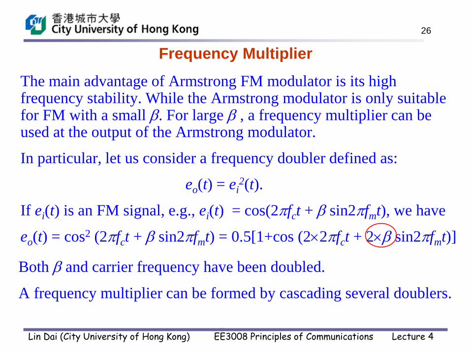
The main advantage of Armstrong FM modulator is its high frequency stability. While the Armstrong modulator is only suitable for FM with a small . For large , a frequency multiplier can be used at the output of the Armstrong modulator.
In particular, let us consider a frequency doubler defined as:
eo(t) = ei2(t).
If ei(t) is an FM signal, e.g., ei(t) = cos(2fct + sin2fmt), we have
eo(t) = cos2 (2fct + sin2fmt) = 0.5[1+cos (22fct + 2 sin2fmt)]
Both and carrier frequency have been doubled.
A frequency multiplier can be formed by cascading several doublers.
Frequency Multiplier
Lin Dai (City University of Hong Kong) EE3008 Principles of Communications Lecture 4

27
FM Demodulator: Slope Detection
( ) cos 2 ( ) :t
FM cs t A f t k s d
( )2 2 ( ) sin 2 ( )
tFM
c c
ds tf ks t A f t k s d
dt
Finally, we briefly discuss the FM demodulator.
Let us take the derivative of an FM signal
The envelope of this signal is:
We can then recover s(t) from this envelope signal by removing
its DC component.
2 2 ( )cA f ks t
Lin Dai (City University of Hong Kong) EE3008 Principles of Communications Lecture 4

28
Summary of FM and AM
Bandwidth
Efficiency
Fidelity
(evaluated by output SNR)
AM
FM
DSB-SC
DSB-C
SSB
VSB
(DSB-C has a lower SNR)
More bandwidth, better fidelity performance
50%
100%
Complexity
high
high
high
low
moderate
~ Pt
~ Pt ~ 2
50% 100%s
s
B
B
50%2(1 )
s
s
B
B
Lin Dai (City University of Hong Kong) EE3008 Principles of Communications Lecture 4