lecture dc machines compatibility mode
TRANSCRIPT
1
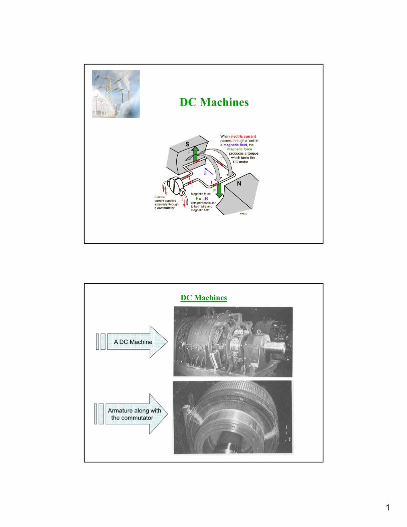
DC Machines
DC Machines
A DC Machine
Armature along with
the commutator

2
Significant Features of DC Machines
• Conventional DC generators are being replaced by the
solid state rectifiers where ac supply is available.
• The same is not true for dc motors because of
– Constant mechanical power output or constant torque
– Rapid acceleration or deceleration
– Responsiveness to feedback signals
• 1W to 10,000 hp
• Applications – in electric vehicles to extend their range
and reduce vehicle weight, in steel and aluminum rolling
mills, traction motors, electric trains, overhead cranes,
control devices, etc.
Introduction
Electromagnetic Energy Conversion:
1. When armature conductors move in a magnetic field produced
by the current in stator field winding, voltage is induced in the
armature conductors.
2. When current carrying armature conductors are placed in a
magnetic field produced by the current in stator field winding,
the armature conductors experience a mechanical force.
These two effects occur simultaneously in a DC machine
whenever energy conversion takes place from electrical to
mechanical or vice versa.

3
Constructional Features of DC Machines
• Commutator along with the armature on the rotor
• Salient-pole on the stator and, except for a few smaller machines, commutating poles between the main poles.
• Field windings (as many as 4):
– Two fields that act in a corrective capacity to combact the detrimental effects of armature reaction, called the commutating (compole or interpole) and compensating windings, which are connected in series with the armature.
– Two normal exciting field windings, the shunt and series windings
Schematic Connection Diagram of a DC Machine

4
Equivalent Circuit of a DC Machine
aaat
fff
RIEV
RIV
±±±±====
====
Ia_gen
If
Vf VtRf
+
- Ea
+
-
Ia_mot
Ra
+
Ia
If
VtRf
Ea
-
IL
Ra
+
+
-
Generated emf and Electromagnetic Torque
aaat
fff
RIEV
RIV
±±±±====
====
mdaa KE ωωωωφφφφ====
adae IKT φφφφ====
meaaem TIEP ωωωω========
Voltage generated in the armature circuit due the flux of the stator field current
Electromagnetic torque
Ka: design constant
Motor: Vt> EaGenerator: Vt > Ea

5
Comparison between the Shunt and Series Connected DC Machines
Speed Control in DC Motors
Shunt motor:
Electromagnetic torque is Te=Ka φd Ia, and the conductor emf is Ea=Vt - RaIa.
For armature voltage control: Ra and If are constant
For field control: Ra and Vt are constant
For armature resistance control: Vt and If are constant
(((( ))))221 etm TKVK −−−−====ωωωω
(((( ))))(((( ))))3
2 e
ff
a
ff
tm T
IK
R
IK
V−−−−====ωωωω
(((( ))))(((( ))))1
2da
ae
da
tm
ada
etmda
K
RT
K
V
RK
TVK
φφφφ−−−−
φφφφ====ωωωω
φφφφ−−−−====ωωωωφφφφ
(((( ))))(((( ))))4
2 e
da
adja
da
tm T
K
RR
K
V
φφφφ
++++−−−−
φφφφ====ωωωω

6
Speed Control in Shunt DC Motors
Armature Voltage Control:
Ra and If are kept constant and the armature
terminal voltage is varied to change the motor
speed.
For constant load torque, such as applied by an
elevator or hoist crane load, the speed will
change linearly with Vt. In an actual
application, when the speed is changed by
varying the terminal voltage, the armature
current is kept constant. This method can also
be applied to series motor.
(((( )))).constis;
KK;
KK
TKVK
d
dada
etm
φφφφφφφφ
====φφφφ
====
−−−−====ωωωω
221
21
11
Field Control:
Ra and Vt are kept constant, field rheostat is varied to
change the field current.
For no-load condition, Te=0. So, no-load speed varies
inversely with the field current.
Speed control from zero to base speed is usually
obtained by armature voltage control. Speed control
beyond the base speed is obtained by decreasing the field
current. If armature current is not to exceed its rated
value (heating limit), speed control beyond the base
speed is restricted to constant power, known as constant
power application.
Speed Control in Shunt DC Motors
mm
aae
meaaat
.constIET
TIEconstIVP
ωωωω====
ωωωω====
ωωωω================
(((( )))) e
ff
a
ff
tm T
IK
R
IK
V2
−−−−====ωωωω

7
Armature Resistance Control:
Vt and If are kept constant at their rated value,
armature resistance is varied.
The value of Radj can be adjusted to obtain
various speed such that the armature current Ia(hence torque, Te=KaφdIa) remains constant.
Armature resistance control is simple to
implement. However, this method is less
efficient because of loss in Radj. This resistance
should also been designed to carry armature
current. It is therefore more expensive than the
rheostat used in the field control method.
Speed Control in Shunt DC Motors
(((( )))) ee
da
adja
da
tm TKKT
K
RR
K
V652
−−−−====φφφφ
++++−−−−
φφφφ====ωωωω
Armature Voltage Control:
A variable dc voltage can be applied to a series motor to
control its speed. A variable dc voltage can be obtained
from a power electronic converter.
Torque in a series motor can be expressed as
Speed Control in Series DC Motors
(((( ))))[[[[ ]]]]
sae
t
sa
sa
sae
tm
samsa
tsa
asaadae
KKT
V
KK
RR
KKT
V,or
RRKK
VKK
IKKIKT
≈≈≈≈++++
−−−−====ωωωω
++++++++ωωωω====
====φφφφ====
2
2
2
(((( ))))(((( ))))
(((( )))) (((( ))))
samsa
ta
saamasa
saamda
saaat
asd
RRKK
VI
RRIIKK
RRIK
RRIEV
IK
++++++++ωωωω====
++++++++ωωωω====
++++++++ωωωωφφφφ====
++++++++====
====φφφφ
8
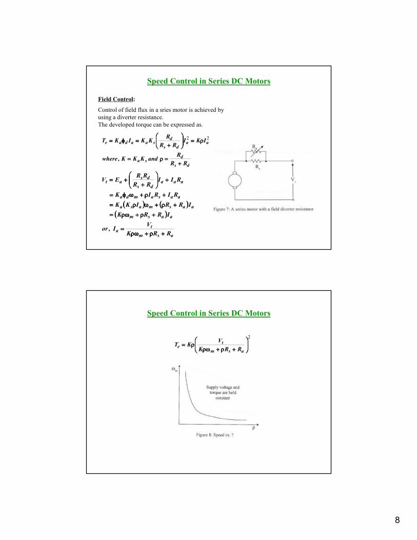
Field Control:
Control of field flux in a sries motor is achieved by
using a diverter resistance.
The developed torque can be expressed as.
Speed Control in Series DC Motors
ds
dsa
aads
dsaadae
RR
RandKKK,where
IKIRR
RKKIKT
++++====ρρρρ====
ρρρρ====
++++====φφφφ==== 22
(((( )))) (((( ))))(((( ))))
asm
ta
aasm
aasmasa
aasamda
aaads
dsat
RRK
VI,or
IRRK
IRRIKK
RIRIK
RIIRR
RREV
++++ρρρρ++++ρωρωρωρω====
++++ρρρρ++++ρωρωρωρω====
++++ρρρρ++++ωωωωρρρρ====
++++ρρρρ++++ωωωωφφφφ====
++++
++++++++====
Speed Control in Series DC Motors
2
++++ρρρρ++++ρωρωρωρωρρρρ====
asm
te
RRK
VKT

9
Armature Resistance Control:
Torque in this case can be expressed as
Rae is an external resistance connected in series with
the armature.
For a given supply voltage and a constant developed
torque, the term (Ra+Rae+Rs+Kωm) should remain
constant. Therefore, an increase in Rae must be
accompanied by a corresponding decrease in ωm.
Speed Control in Series DC Motors
(((( ))))
K
RRR
KT
V,or
VT
KKRRR,or
T
KVKRRR
sadja
e
tm
te
msadja
e
tmsadja
++++++++−−−−====ωωωω
====ωωωω++++++++++++
====ωωωω++++++++++++2
2
(((( ))))22
msadja
te
KRRR
KVT
ωωωω++++++++++++====
Power Division in DC Machines
Input from
prime-mover
Elec-magnetic
Power =EaIa
Arm. terminal
power = Vta Ia
Output power
= Vt IL
No-load rotational loss (friction
+windage+core)+stray load loss
Arm. copper loss
Ia2Ra+brush contact loss
Series field loss IL2Rs
+shunt field loss If2Rf
Input power from
mains =Vt IL
Elec-magnetic
Power =EaIa
Arm. terminal
power = Vta Ia
Output available
at the shaft
No-load rotational loss (friction
+windage+core)+stray load loss
Arm. copper loss
Ia2Ra+brush contact loss
Series field loss IL2Rs
+shunt field loss If2Rf
DC Motor
DC Generator

10
Efficiency
InputPower
Losses
InputPower
LossesInputPower
InputPower
OutputPower
−−−−====
−−−−====
====ηηηη
1
The losses are made up of rotational losses (3-15%), armature
circuit copper losses (3-6%), and shunt field copper loss (1-5%).
The voltage drop between the brush and commutator is 2V and
the brush contact loss is therefore calculated as 2Ia.
DC Machines Formulas

11
Problem 9-1 to 9-7 (Page 621)
Solution to Problem 9-1 (Page 621)

12
Solution to Problem 9-2 (Page 621)
Solution to Problem 9-5 (Page 621)

13
Problem 9-13 (Page 623)
Solution to Problem 9-13 (Page 623)

14
Solution to Problem 9-13 (Page 623)
The End