lecture note #1 iit kharagpur st1 semester, 2019 short
TRANSCRIPT

Lecture Note #1 IIT Kharagpur 1st Semester, 2019
Short Course
Design of Aircraft Components using Composite Materials
787 Dream Liner
Eurofighter Typhoon
Indian Institute of Technology-Kharagpur Department of Aerospace Engineering
Professor Changduk Kong
Dept. of Aerospace Engineering, Gas turbine Lab.
【Course Title】 Design of Aircraft Components using Composite Materials
【Instructor】 Family Name: KONG Given Name: Changduk Nationality: Republic of Korea Academic Titles: Professor(Emeritus)/Visiting Professor/Invited Professor /Invited Professor /Director/CTO/President Currently Work in: Chosun University/IIT Kharagpur/Korea Aerospace University/ Beihang University/AMRC(UK)- Korea/EGT /Korea Society for Naval Science & Technology Email Address: [email protected] / [email protected]
Lecture Syllabus
Dept. of Aerospace Engineering, Gas turbine Lab.
【Teaching Language】 English 【Credits/Credit Hours】 3/42 【Students】 4 years undergraduate students, post graduate students 【Size of Class】 Less than 40 【Prerequisites & Requirements】 Strength of Materials, aerospace structure, composite materials 【Methods of Instruction】 Lecture and design practice (Theory and Tutorial)
Lecture Syllabus

Dept. of Aerospace Engineering, Gas turbine Lab.
【Performance Evaluation】 Performance will be graded according to both the exam results and evaluation by homework and quizzes; exam 70% / attendance 10% / homework and quizzes 20/% of the total result 100%
【About the Instructor】 Prof. Changduk Kong graduated with a BSc in Aerospace Engineering from the Korea Aerospace University (national) and a PhD in Aerospace Engineering from the Osaka Prefecture University, Japan. He worked as Head of the Aero-Propulsion Division of ADD (Agency for Defense Development (1978-1994). He served as Professor at Department of Aerospace Engineering of Chosun University (1994-2016), and was appointed as Dean of the School of Aerospace and Naval Architecture Engineering (1999 and 2005-2006), and Dean of the Facility Management Office at Chosun University (2011-2012). Prof. Kong has contributed greatly to the development of Aerospace Engineering in Korea, primarily through his roles as Director of KIAST(Korea Institute of Aviation Safety Technology) (2015-2018), Director of AMRC(UK)-Korea (2015-2019) President of KSNST(Korean Society for Naval Science and Technology) (2017-2020), President of SASE(The Society for Aerospace System Engineering) (2013-2016), President of ICRC (International Collaboration Research Centre in Natural Composites, Chosun University (2012-2014), President of KSAS(The Korean Society for Aeronautical and Space
Lecture Syllabus
Dept. of Aerospace Engineering, Gas turbine Lab.
Sciences (2010), President of KSPE(The Korean Society of Propulsion Engineers (2007-2008), Chair of Cycle Innovation-IGTI-ASME (2009-2011), President of RIME(Research Institute of Mechanical Engineering-Chosun University (2006-2008), and First Lieutenant of ROKAF (Republic of Korea Air Forces (1974-1978). He was Visiting Professor at Imperial College London (2001-2002), and he is Invited as Invited Professor at Korea Aerospace University (2016-2018), Invited Professor at Summer School of Beihang University (2017-2018) and Vising Professor at IIT-Kharagpur (2017, 2019-20121). He is the Editorial Board Members of IJTJ(International Journal of Turbo & Jet Engines), IJCM(International Journal of Composite Materials), CJS(Chinese Journal of Aeronautics) and AEAT(Aircraft Engineering and Aerospace Technology), and Editor-in-Chief of JKSAS(Journal of Korean Society for Aeronautical and Space Science) and JKSPE(Journal of Korean Society of Propulsion Engineers) (2006-2010). He received the Korean National Decoration in Science for his scientific achievement and contribution to Korean aerospace development, Academic Achievement Awards from KSAS, SASE and KSPE and the 2015 KAI-KSAS Prize. Prof. Kong has authored and co-authored more than 611 papers including 61 SCI journal papers, and has received numerous lecture invitations from companies, research institutes and universities and delivered eight keynotes and invited lectures at international conferences. He has organized 25 national conferences, forums and workshops and was co-organizer on four international conferences.
Lecture Syllabus

Dept. of Aerospace Engineering, Gas turbine Lab.
【Course Description】 Recently, advanced aerospace vehicles tend to reduce the weight as well as improve the economic efficiency using the advanced composite materials and the simplification of manufacturing process. Therefore in order to understanding more the composite materials structures this lecture introduces firstly kinds and behaviors of matrixes and reinforcements, manufacturing methods, test methods and inspection methods, and teaches design procedure and method of aerospace vehicle structure, laminates analysis method and application examples, and finally provides a design capability through some design examples of typical aircraft composite component structures and a case study on design of regional aircraft fuselage floor beam.
【Syllabus】 42days (6 weeks) course (basically 2days per a week, 4 hours per a day)
Lecture Syllabus

Dept. of Aerospace Engineering, Gas turbine Lab.
< Module 1 ( 4 hours)> Subject : Introduction of composite Materials Contents : Definition of composite materials, kinds of composite materials, kinds and behaviors of matrixes/reinforcements/interface, terminologies related to composite materials. Mechanical behaviors of composite materials, selection of composite materials, laminate laying-up, structure design and analysis, and manufacturing method < Module 2 ( 8 hours)> Subject : Fundamentals of composite materials structural mechanics Contents : Macro-Mechanics, laminate stress-strain relation, rule of mixture, Failure Criteria of composite materials, Laminate Strength Analysis, residual stress, notch stress, methods of design data measuring, behaviors of fatigue/impact/water absorption/ corrosion, and repair methods < Module 3 ( 4 hours)> Subject : Composite materials laminate analysis and design Contents : Analytical laminate analysis method, experimental analysis method, laminate design example, thin wall section design
Lecture Syllabus

Dept. of Aerospace Engineering, Gas turbine Lab.
<Module 4 (2 hours > Subject : Mid term exam and evaluation < Module 5 ( 6 hours)> Subject : Design of composite materials structure Contents : - Design procedures, definition and methods (structure concept, shape,
cross section, manufacturing, fatigue life, stiffening, joints, material type, selection criteria, manufacturing process), Design review and analysis (strength, stiffness, stability, secondary load, thickness wise stress, hole and notch, bolt joint, bonding joint, sandwich, fatigue, impact, design limit, cost, weight, manufacturing process and cost, trade-off)
< Module 6 ( 8 hours)> Subject : Design examples of several typical aircraft composite components Contents : - Composite laminate design with given loads: comparison of QI design method and PS design
Lecture Syllabus

Dept. of Aerospace Engineering, Gas turbine Lab.
- Comparison of laminate analysis methods of strength and stiffness such as laminate analysis method, netting rule, Hart-Smith 10% rule, Carpet plot method of cross ply, angle ply and quasi-isotropic laminates - Composite panel buckling calculation examples loaded by uniaxial compression loading and in-plane shear loading, and comparison with Al alloy panel buckling - Thin wall section designs : 1) C type channel structure loaded by axial load, shear load, bending moment and torsional moment 2) Thin wall box beam structure loaded by axial load, shear load, bending moment and torsional moment
Lecture Syllabus

Dept. of Aerospace Engineering, Gas turbine Lab.
< Module 7 ( 4 hours)> Subject : Case study of composite materials structure design Contents : Design of regional aircraft fuselage floor beam; - Design of new composite floor beam for reduced weight, minimum cost and reduced number of parts from given original metal floor beam using composite materials, the proposed design process by define, scheme, check, refine and trade-off with consideration of structure, material and manufacture concurrently. < Module 8 ( 4 hours)> Subject : Case study of composite materials structure design Contents : Design of Wing Spar of Light Airplane; - Design of new wing spar to reduce weight, cost and number of parts from
given original metal spar using composite materials using the proposed design process by define, scheme, check, refine and trade-off with consideration of structure, material and manufacture concurrently
<Module 9 (2 hours)> Subject : Final term exam and evaluation
Lecture Syllabus

Dept. of Aerospace Engineering, Gas turbine Lab.
【Textbooks and References】 1. C. Kong, 'Lecture notes- Aerospace Composite Structures', Beihang University, 2018 2. M.C.Y. Niu, 'Composite airframe structures', Hon Kong Comilit Press Ltd., 1996 3. R. F. Gibson, 'Principles of Composite Material Mechanics', McGraw-Hill Inc., 1994 4. E. J. Jeon et al., 'Advanced Composite materials', Gyohaksa Ltd., 1995 5. M. H. Datoo, ‘Mechanics of Fibrous Composites’, Elsevier Applied Science, 1991
【Textbooks and References】 1. C.D. Kong et al., 2005, Structural investigation of composite wind turbine blade considering various load cases and fatigue life, Energy, Vol. 30, pp. 2101-2114 2. C.D. Kong et al., 2006, Investigation of fatigue life for a medium scale composite wind turbine blade, International Journal of Fatigue, Vol. 28, pp. 1382-1388 3. C.D Kong et al., 2016, Design and manufacturing of automobile hood using natural composite structure, Composites Part B, Vol. 91, pp. 18-26 3. 4. C.D. Kong et al., 2013, Development of a high-efficiency and long-life 500W class
H-Darrieus type vertical axis wind turbine(VAWT) system using skin-spar-foam sandwich composite structure, Science and Engineering of Composite Materials, Vol. 20, pp. 383-394
Lecture Syllabus
Dept. of Aerospace Engineering, Gas turbine Lab.
5. C.D. Kong et al., 2013, Study on design of high efficiency and light weight composite propeller blade for a regional turboprop aircraft, International Journal of Turbo & Jet-Engines, Vol. 30, pp. 33-42 6. C.D. Kong et al., 2008, A study on conceptual structural design of wing for a small scale WIG craft using carbon/epoxy and foam sandwich composite structure, Advanced Composite Materials, Vol. 17, pp. 343-358 7. C.D. Kong et al., 2008, Preliminary design for the fuselage of a small scale WIG craft using composite materials, Science and Engineering of Composite Materials, Vol. 15, pp. 189-206
Lecture Syllabus

Composite aircrafts Faster, lighter, smarter
Greener, Quieter, Safer,…
INTRODUCTION
Indian Institute of Technology-Kharagpur Department of Aerospace Engineering
Professor Changduk Kong
Dept. of Aerospace Engineering, Gas turbine Lab.
Outline Background What are composites?
Why use them?
What forms do they take?
Near future R&D in Aerospace composites Status of Aerospace Composites in Korea
Part 1 INTRODUCTION

Dept. of Aerospace Engineering, Gas turbine Lab.
What are composites?
Composites combine the properties of two or more materials (constituents). Any two materials (metals, ceramics, polymers, elastomers, glasses) could be combined to make a composite.
They might be mixed in many geometries (particulate, chopped-fibre, woven, unidirectional fibrous and laminate composites) to create a system with a property profile not offered by any monolithic material. In mechanical design it is often to improve the stiffness-to-weight
ratio or strength-to-weight ratio or improve toughness In thermo-mechanical design, it is to reduce thermal expansion, or to
maximise heat transfer, or to minimise thermal distortion.
Dept. of Aerospace Engineering, Gas turbine Lab.
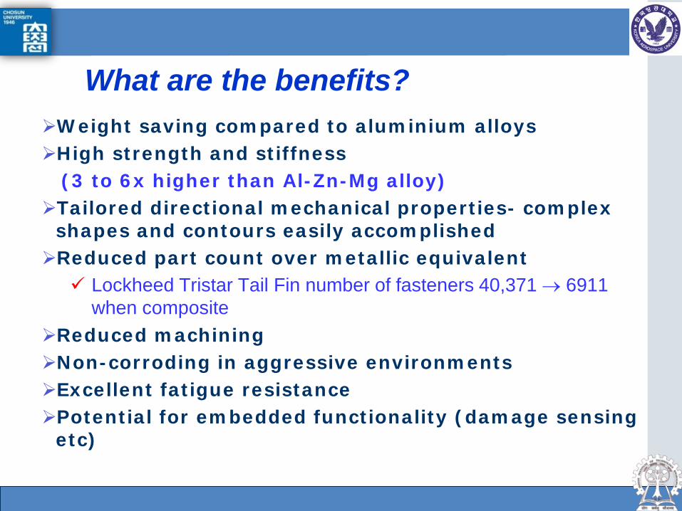
What are the benefits? Weight saving compared to aluminium alloys High strength and stiffness (3 to 6x higher than Al-Zn-Mg alloy) Tailored directional mechanical properties- complex
shapes and contours easily accomplished Reduced part count over metallic equivalent Lockheed Tristar Tail Fin number of fasteners 40,371 → 6911
when composite Reduced machining Non-corroding in aggressive environments Excellent fatigue resistance Potential for embedded functionality (damage sensing
etc)
Dept. of Aerospace Engineering, Gas turbine Lab.
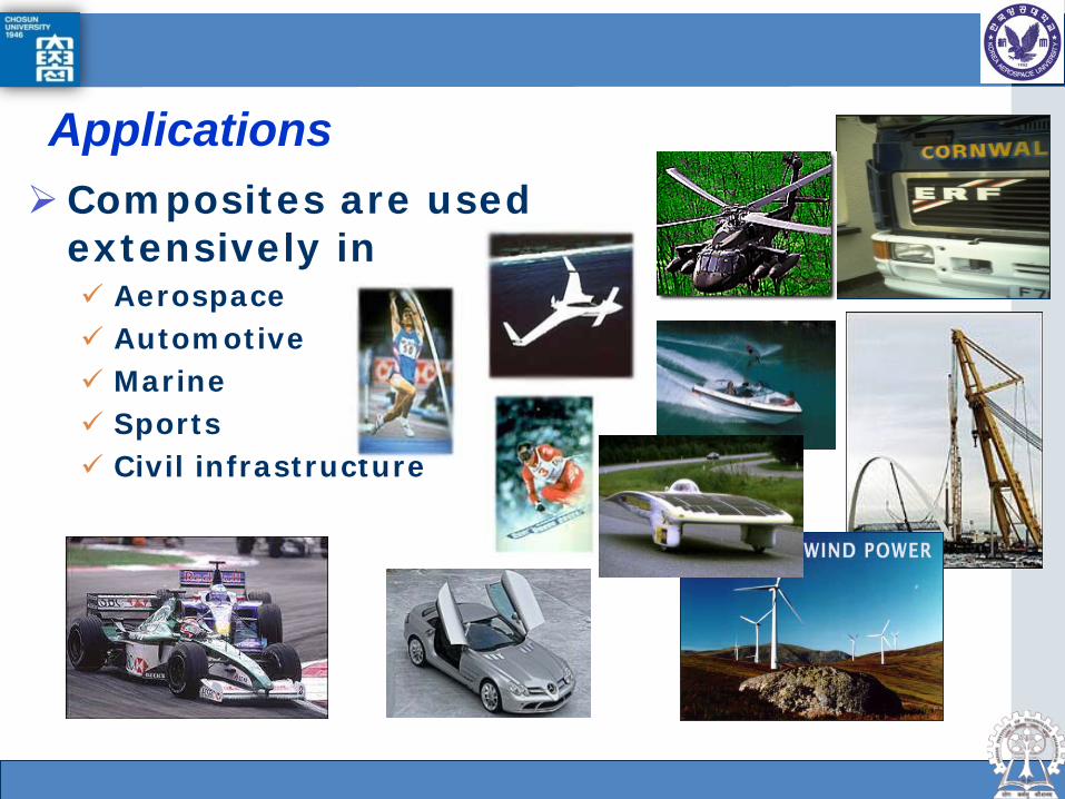
Applications Composites are used
extensively in Aerospace Automotive Marine Sports Civil infrastructure

Dept. of Aerospace Engineering, Gas turbine Lab.
Carbon Fiber Industrial Status
World Market of CFRP - Aerospace CFRP market will grow to 47,000 MT in 2020
Aerospace CFRP market
MT : metric ton= 1000kg

Dept. of Aerospace Engineering, Gas turbine Lab.
Carbon Fiber Industrial Status
World Market of CFRP - Aerospace CFRP market will grow to USD 15 Billion in 2020
* AAGR: Average Annual Growth Rate 15%!
Aerospace CFRP market
Dept. of Aerospace Engineering, Gas turbine Lab.
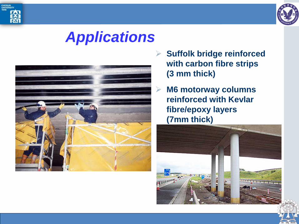
Applications Suffolk bridge reinforced
with carbon fibre strips (3 mm thick)
M6 motorway columns reinforced with Kevlar fibre/epoxy layers (7mm thick)

Dept. of Aerospace Engineering, Gas turbine Lab.
Applications F1 Ferrari with a carbon fibre
chassis weighs less than 600kg with oil, water and driver!
4.495 m long, 1.79m wide and 0.959m high
San Marino, 25 April 2004

Dept. of Aerospace Engineering, Gas turbine Lab.
Typical Composite Failure Sequence
1. Resin cracks
2. Interface failure
3. Fibre pull-out
4. Fibre fracture
Applications
Dept. of Aerospace Engineering, Gas turbine Lab.
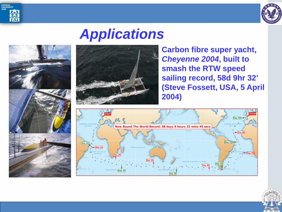
Applications Carbon fibre super yacht, Cheyenne 2004, built to smash the RTW speed sailing record, 58d 9hr 32’ (Steve Fossett, USA, 5 April 2004)

Dept. of Aerospace Engineering, Gas turbine Lab.
Virgin Atlantic Global Flyer Built by Scaled
Composites (Mojave, USA)
1st test flight on 5 March 2004, 1hr 30’
It can carry >4x its own weight in fuel. TOW is 22,000lbs
The plane flew up to 52,000ft and travelled at speeds of 290mph
Non-stop RTW flight in February 2005 <80hrs
Steve Fossett Williams FJ44-3 turbofan engine Unfortunately millionaire, adventurer, sailor and aviator Steve died in 2007 due to plane crash!
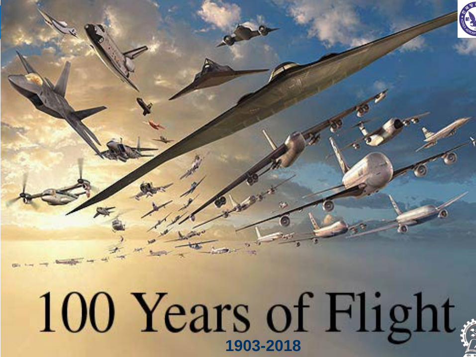
Dept. of Aerospace Engineering, Gas turbine Lab. 1903-2018

Dept. of Aerospace Engineering, Gas turbine Lab.
Earlier Planes In the pioneering days of flight,
a/c structures were composite, being fabricated largely of wood (natural composite), wire and fabric
Aluminium alloys took over in 1930s and have dominated the industry to the present time.
Boeing wing 1922 Spitfire
Dept. of Aerospace Engineering, Gas turbine Lab.
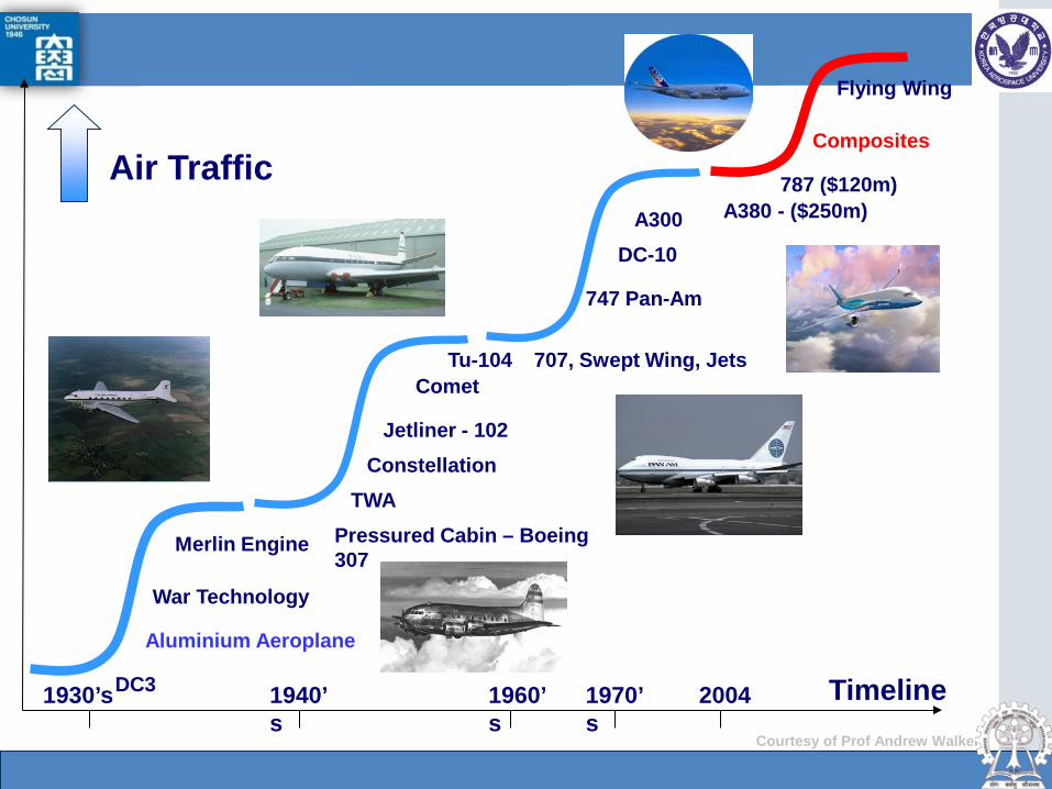
Air Traffic
DC3
Aluminium Aeroplane
War Technology
Merlin Engine Pressured Cabin – Boeing 307
Constellation TWA
707, Swept Wing, Jets
747 Pan-Am
A300 A380 - ($250m) 787 ($120m)
Composites
Jetliner - 102
Comet Tu-104
DC-10
1930’s 1940’s
1960’s
1970’s
2004
Flying Wing
Timeline Courtesy of Prof Andrew Walker
Dept. of Aerospace Engineering, Gas turbine Lab.
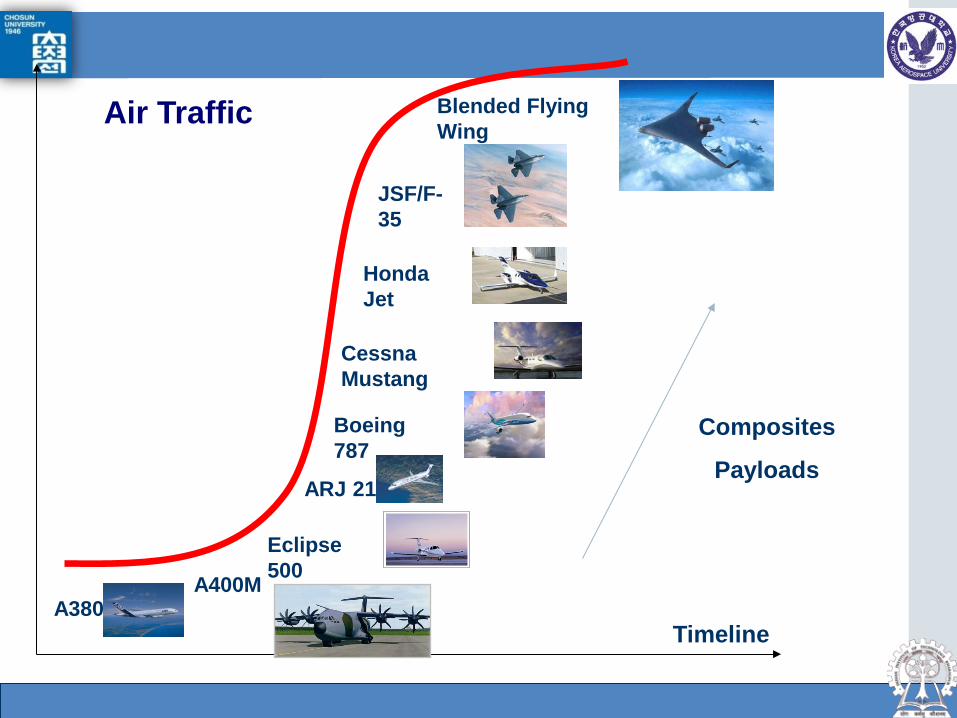
Timeline A380
A400M
Eclipse 500
ARJ 21
Boeing 787
Cessna Mustang
Honda Jet
JSF/F-35
Blended Flying Wing
Composites
Payloads
Air Traffic

Dept. of Aerospace Engineering, Gas turbine Lab.
Civil Aerospace
Increasing use of composites All secondary structure and tail structure mainly
composite already – Airbus and to lesser extent Boeing leading / trailing edges, flaps spoilers, fairings, access panels,
engine nacelles Recent Airbuses also have composite
horizontal/vertical stabilisers, fuselage keel beams and wing leading edges
Airbus, 550-seat A380 super jumbo, also has a lot of composite primary structure
Dept. of Aerospace Engineering, Gas turbine Lab.
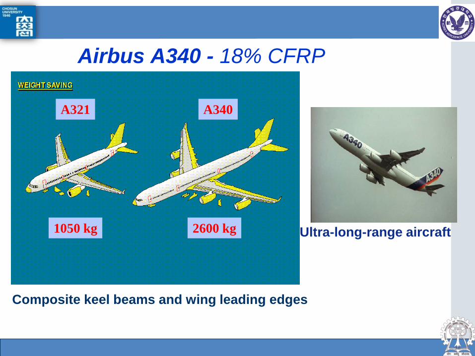
Airbus A340 - 18% CFRP
Composite keel beams and wing leading edges
1050 kg 2600 kg
A321 A340
Ultra-long-range aircraft
Dept. of Aerospace Engineering, Gas turbine Lab. KOREANAIR PROPRIETARY COPYRIGHT © 2008 THE KOREAN AIR COMPANY
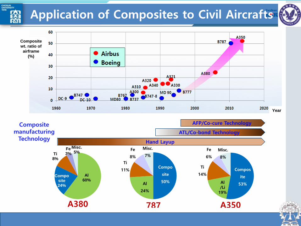
Hand Layup
Composite manufacturing
Technology
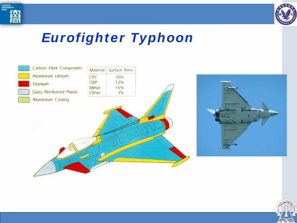
Al 60%
Composite 24%
Ti 8%
Fe 3%
Misc. 5%
A380
Compos
ite
53% Al /Li
19%
Ti
14%
Fe
6%
Misc.
8%
A350
Compo
site
50% Al
24%
Ti
11%
Fe
8%
Misc.
7%
787
ATL/Co-bond Technology
AFP/Co-cure Technology
Application of Composites to Civil Aircrafts
Composite wt. ratio of
airframe (%)
Year

Dept. of Aerospace Engineering, Gas turbine Lab. KOREANAIR PROPRIETARY COPYRIGHT © 2008 THE KOREAN AIR COMPANY
Aluminum 20%
Titanium 15%
Steel 10%
Other 5%
Composites 50%
Carbon laminate Carbon sandwich Other composites Aluminum Titanium Titanium/steel/aluminum
Boeing 787 Airbus 350
Carbon laminate Carbon sandwich Other composites Aluminum Titanium Aluminum
19%
Titanium
14%
Steel 6%
Other 8%
Composites
53%
Composite Wt. ratio of B787 Airframe : 50% (Volume ratio: 80%) Wt. Reduction : 10~ 20% (12~ 24 ton )
Application of Composites to Civil Aircrafts
Dept. of Aerospace Engineering, Gas turbine Lab.
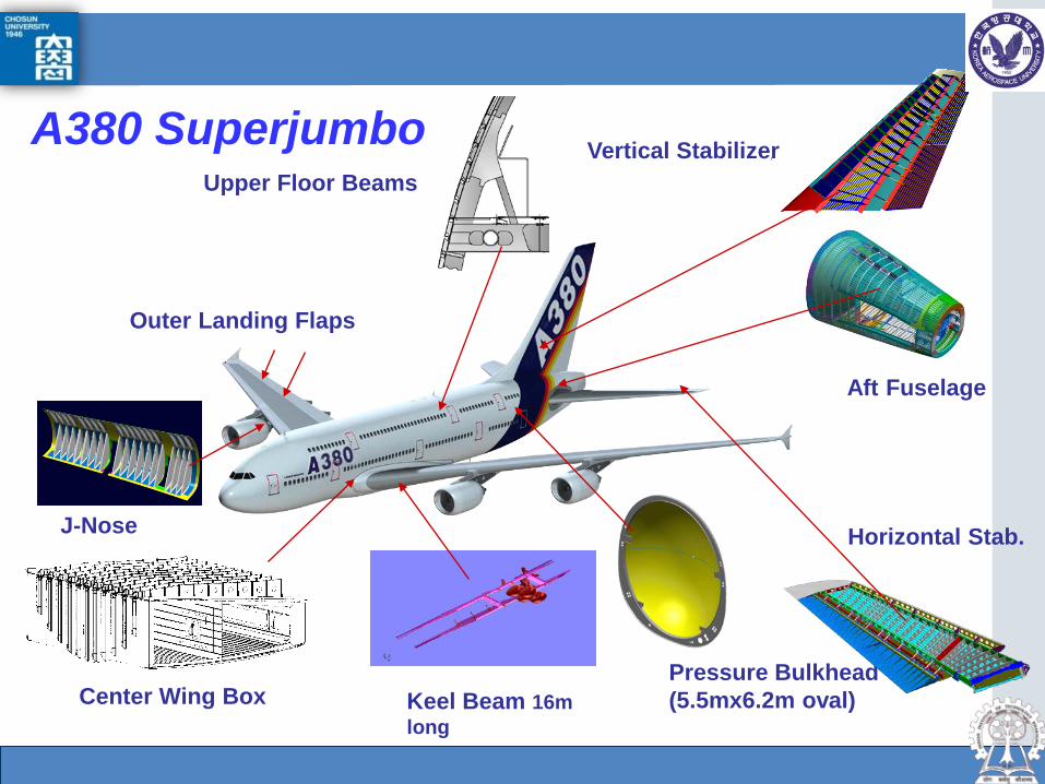
Upper Floor Beams
Pressure Bulkhead (5.5mx6.2m oval)
Horizontal Stab.
Vertical Stabilizer
Outer Landing Flaps
Center Wing Box
Aft Fuselage
A380 Superjumbo
Keel Beam 16m long
J-Nose
Dept. of Aerospace Engineering, Gas turbine Lab.
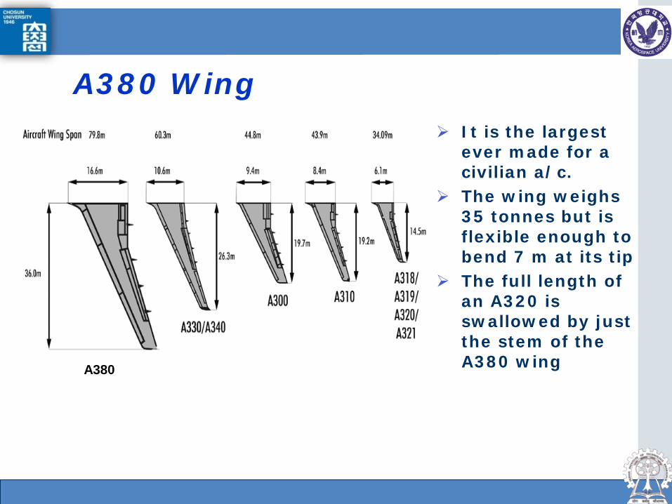
A380 Wing It is the largest
ever made for a civilian a/c.
The wing weighs 35 tonnes but is flexible enough to bend 7 m at its tip
The full length of an A320 is swallowed by just the stem of the A380 wing A380

Dept. of Aerospace Engineering, Gas turbine Lab.
The first set of wings left Broughton in April 2004
Too large even for Airbus whale-shaped Beluga air freighter, they travelled by barge down the river Dee and then in a specially built cargo ship to Bordeaux. From there they were taken by road to Toulouse
The Broughton and Filton factories employ more than 12,000 workers and another 84,000 jobs at its myriad subcontractors, 22,000 of those on A380 work alone
Airbus spent nearly £2b in the UK on production facilities for the A380
A380 Wing
The Broughton factory in North Wales

Dept. of Aerospace Engineering, Gas turbine Lab.
Centre Wing Box
A380 is the first aircraft with a CFRP centre wingbox Made by Automatic Tape Laying (ATL) 8.8 tonnes, with 5.3 tonnes of CFRP, saving over 1.5
tonnes compared to the metallic equivalent Main challenge is the wing root joint, with
composites up to 45mm thick ! Links to CFRP keel beams, each 16 m long and
23mm thick carrying 450 tonnes

Dept. of Aerospace Engineering, Gas turbine Lab.
Centre Wing Box

Dept. of Aerospace Engineering, Gas turbine Lab.
Horizontal Tailplane Composite Torsion Box Demonstrator
ATL component
Made by CASA Same size as
A320 wing, 14.5m

Dept. of Aerospace Engineering, Gas turbine Lab.
Structural Test for A380 Horizontal Tail

Dept. of Aerospace Engineering, Gas turbine Lab.
UK Military Aircraft Transport Aircraft
Airbus A400M - 40 tonne load capacity
Lockheed Hercules C130J - 12 tonne load capacity
Eurofighter Typhoon In-service 2002 Update, Air-Ground version in
2008 F-35 Joint Strike Fighter,
Lockheed Supersonic, STOVL propulsion
system(F-35B) Lockheed
F-35
A400M
C130J Typhoon
Dept. of Aerospace Engineering, Gas turbine Lab.
Eurofighter Typhoon

Dept. of Aerospace Engineering, Gas turbine Lab.
US Civil Aircraft The 787 is 50% composites of weight, and 20,000lb lighter than the Airbus A330-200, for 3,150Km more range with 250 passengers. 20% cheaper to operate
Laminated composites are used allowing a ‘smart layer’ of PZT
transducers to be inserted for structural health monitoring
The new RR Trent 1000 engine was chosen by Boeing (April 2004) as one of two engines that could bring £65bn to RR (or GE GENEX).
1st order of 50 787 by All Nippon Airways of Japan, $6bn, delivery 2008 (27 April 2004)
Boeing hopes to sell more than 3000 of this medium size airliner
787 Dreamliner
More than 50% non-US content! By Risk Share Partnership!

Dept. of Aerospace Engineering, Gas turbine Lab.
US Military Aircraft
F16
F22 Raptor
B1
C17 F-117
B-2 Stealth Bomber

Dept. of Aerospace Engineering, Gas turbine Lab.
Russian Planes
A-40 amphibian
An-70 Transport
Su47&Su27
Sukhoi-47 5th generation multi-functional frontal fighter
Features FS composite wing structure and incorporates LO and TV
FSW better performance at high AoA much needed in close-in dogfight
Dept. of Aerospace Engineering, Gas turbine Lab.
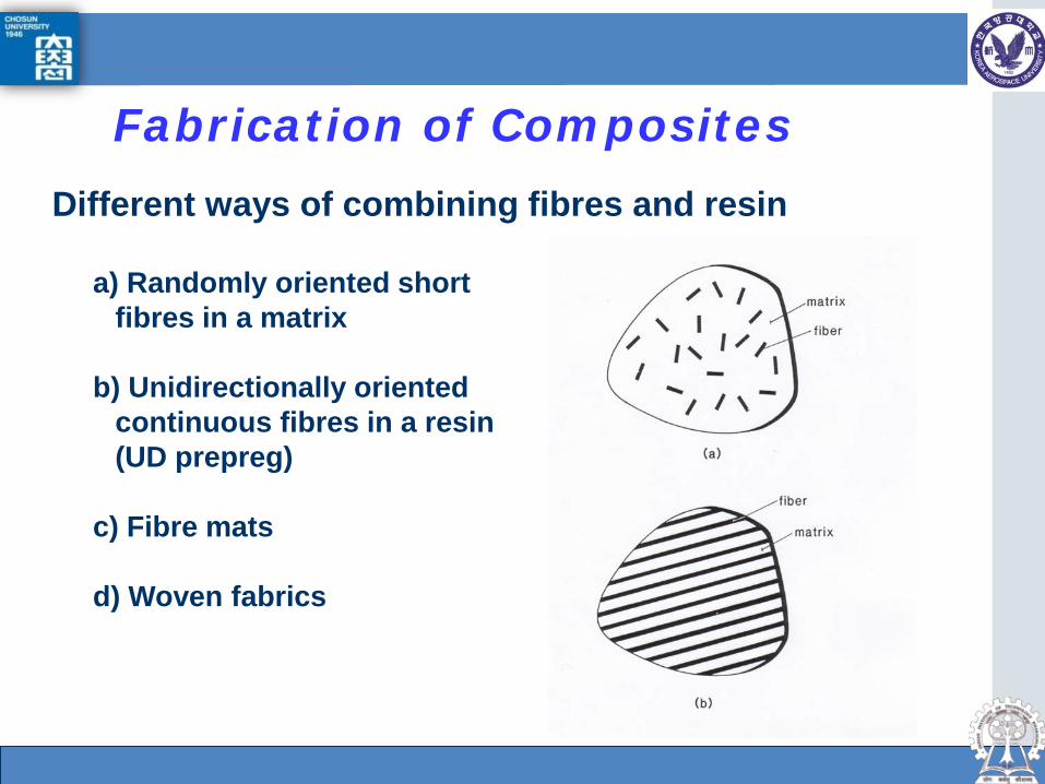
Different ways of combining fibres and resin
a) Randomly oriented short fibres in a matrix
b) Unidirectionally oriented continuous fibres in a resin (UD prepreg)
c) Fibre mats
d) Woven fabrics
Fabrication of Composites

Dept. of Aerospace Engineering, Gas turbine Lab.
Different Reinforcing Fabric Weaves
Unidirectional Plain Basic (triaxial) weave Basic basket weave
Twill 2.2 Satin 8 Bi-plain weave (filling 60° to warp)
Bi-plain weave (filling 45° to warp)

Dept. of Aerospace Engineering, Gas turbine Lab.
Continuous or very long fibres aligned to principal stress High performance Anisotropic properties Limited shapes
Dispersed short Fibres Complex shapes High production rates Poor performance
Fibre mats Simple shapes but more complex curvatures
Woven continuous fibres * Compromise between speed – complexity - performance
Fabrication of Composites
Dept. of Aerospace Engineering, Gas turbine Lab.
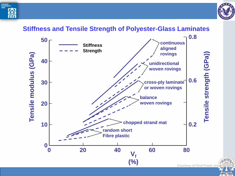
Stiffness and Tensile Strength of Polyester-Glass Laminates
40
30
20
10
0 0 20 40 80 Vf
(%)
Tens
ile m
odul
us (G
Pa)
60
50
0.6
0.2
0.8
chopped strand mat random short Fibre plastic
balance woven rovings
cross-ply laminate or woven rovings
unidirectional woven rovings
continuous aligned rovings
Tens
ile s
tren
gth
(GPa
))
Courtesy of Prof Frank Jones
Stiffness Strength

Dept. of Aerospace Engineering, Gas turbine Lab.
Manufacturing methods Autoclave
Resin Injection
Filament winding
Pultrusion
Hand lay-up moulding
Spray-up-moulding
RTM, VARTM, RIFT, ATP
Courtesy of Prof Frank Jones
RTM
*Resin Transfer Moulding (RTM) *Resin Infusion under Flexible Tooling (RIFT)
Filament winding
RTM
Dept. of Aerospace Engineering, Gas turbine Lab.
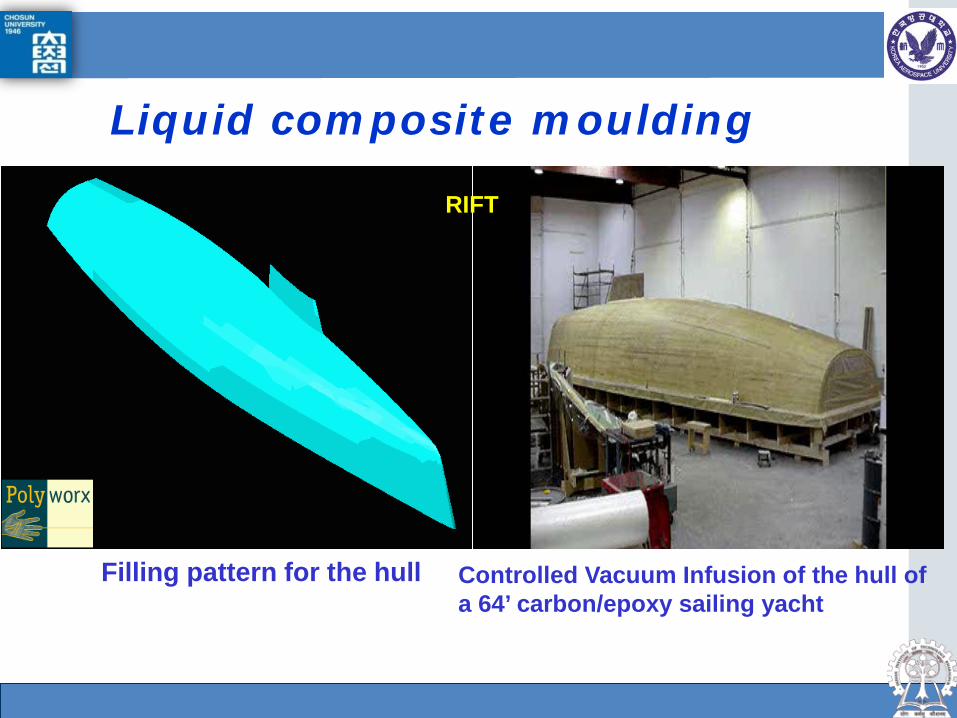
Liquid composite moulding
Controlled Vacuum Infusion of the hull of a 64’ carbon/epoxy sailing yacht
Filling pattern for the hull
RIFT

Dept. of Aerospace Engineering, Gas turbine Lab.
Development of flax/vinyl ester natural fiber composite agricultural chemical container using Vacuum Assisted Resin Transfer Molding-Light(VARTML)
Vacuum Assisted Resin Transfer Molding-Light (VARTML)

Dept. of Aerospace Engineering, Gas turbine Lab.
Application of VARTM-Light manufacturing technology
Flax biaxial woven
fabric (600g/m2)
Polyvinyl ester KRF-1031

Dept. of Aerospace Engineering, Gas turbine Lab.
Resin flow analysis results using Polyworx
Upper Part Lower Part
Front Part Side Part
Dept. of Aerospace Engineering, Gas turbine Lab.
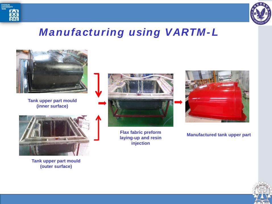
Manufacturing using VARTM-L
Tank upper part mould (inner surface)
Tank upper part mould (outer surface)
Flax fabric preform laying-up and resin
injection
Manufactured tank upper part

Dept. of Aerospace Engineering, Gas turbine Lab.
Visual and UT NDT Inspection, Hydrostatic pressure
proof test and sealing test
Tank assembly by bonding
Parts manufactured by VARTML
Manufacturing using VARTM-L
Dept. of Aerospace Engineering, Gas turbine Lab.
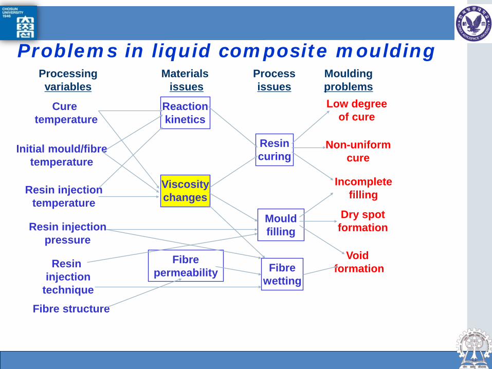
Problems in liquid composite moulding Processing variables
Materials issues
Process issues
Moulding problems
Cure temperature
Reaction kinetics
Low degree of cure
Initial mould/fibre temperature
Resin injection temperature
Resin injection
technique Fibre structure
Resin curing
Viscosity changes
Mould filling
Fibre permeability Fibre
wetting
Resin injection pressure
Non-uniform cure
Incomplete filling
Dry spot formation
Void formation
Dept. of Aerospace Engineering, Gas turbine Lab.
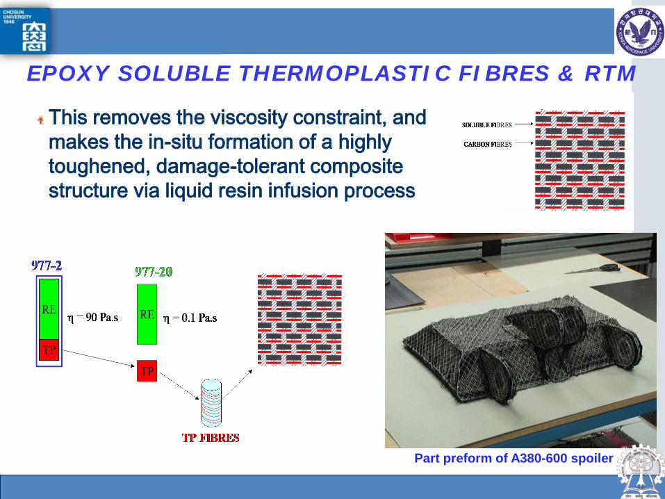
EPOXY SOLUBLE THERMOPLASTIC FIBRES & RTM
This removes the viscosity constraint, and makes the in-situ formation of a highly toughened, damage-tolerant composite structure via liquid resin infusion process
Part preform of A380-600 spoiler
Dept. of Aerospace Engineering, Gas turbine Lab.
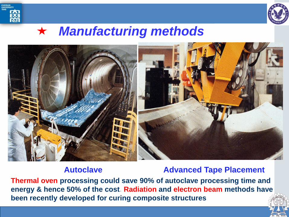
Manufacturing methods
Advanced Tape Placement Autoclave Thermal oven processing could save 90% of autoclave processing time and energy & hence 50% of the cost. Radiation and electron beam methods have been recently developed for curing composite structures

Dept. of Aerospace Engineering, Gas turbine Lab.
Complex inlet duct manufacture (JSF) by ATP
JSF/F-35

Dept. of Aerospace Engineering, Gas turbine Lab.
Microwave Curing Method can reduce 40% curing time and 80% energy consumption comparing to Autoclave Curing Method.
Reduce greatly manufacturing cost
MICROWAVE Curing Method
Microwave Autoclave
Indirect heating direct heating
ATP Thermoplastic Prepreg
Microwave Prototype

Dept. of Aerospace Engineering, Gas turbine Lab.
Laminates Used to tailor directional mechanical properties
Multiple fracture of individual lamina
Provide toughness
To satisfy these stress conditions we need: 2 plies in x-direction, 4 +/-45 plies 1 ply in the y-direction
Dept. of Aerospace Engineering, Gas turbine Lab.
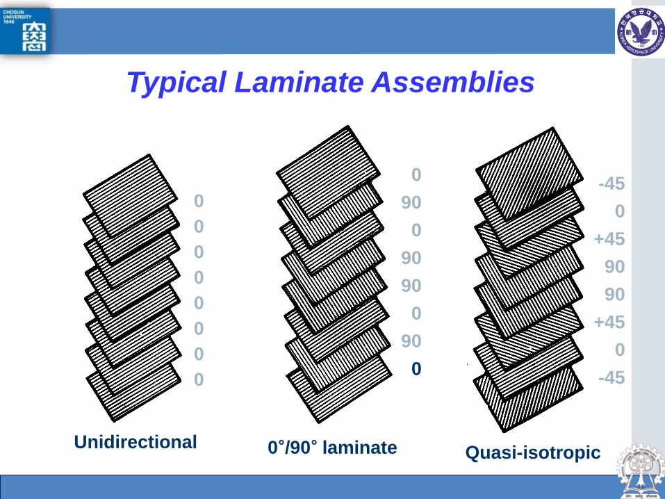
Typical Laminate Assemblies
0 0 0 0 0 0 0 0
0 90
0 90 90
0 90
0
-45 0
+45 90 90
+45 0
-45
0°/90° laminate Quasi-isotropic Unidirectional
Dept. of Aerospace Engineering, Gas turbine Lab.
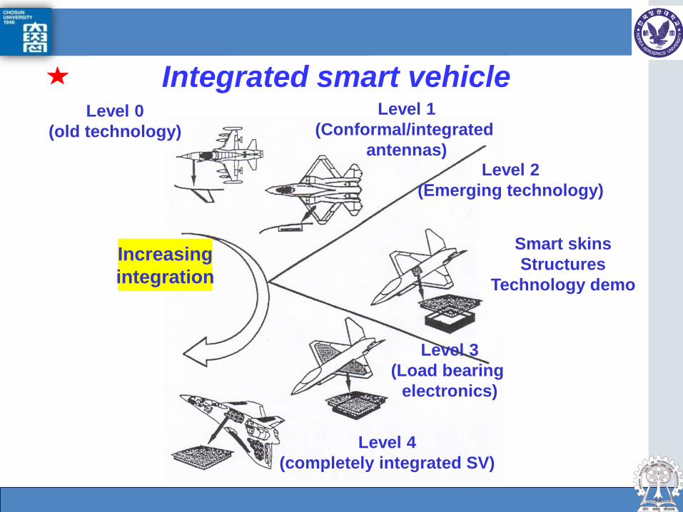
Integrated smart vehicle
Increasing integration
Level 0 (old technology)
Level 1 (Conformal/integrated
antennas) Level 2
(Emerging technology)
Smart skins Structures
Technology demo
Level 3 (Load bearing
electronics)
Level 4 (completely integrated SV)

Dept. of Aerospace Engineering, Gas turbine Lab.
Design of a Laminate The fundamental problems in composites are to determine the stresses and deformation within each layer in terms of known load resultants and the prediction of onset of failure in a layer and its progression towards final failure
In regions remote from boundaries and stress raisers the analysis of stresses is readily accomplished by LPT
Prediction of failure is far less satisfactory Need for improved design tools to cover local stress details (OHC, impact, CAI) but also life prediction and damage and damage growth
Dept. of Aerospace Engineering, Gas turbine Lab.
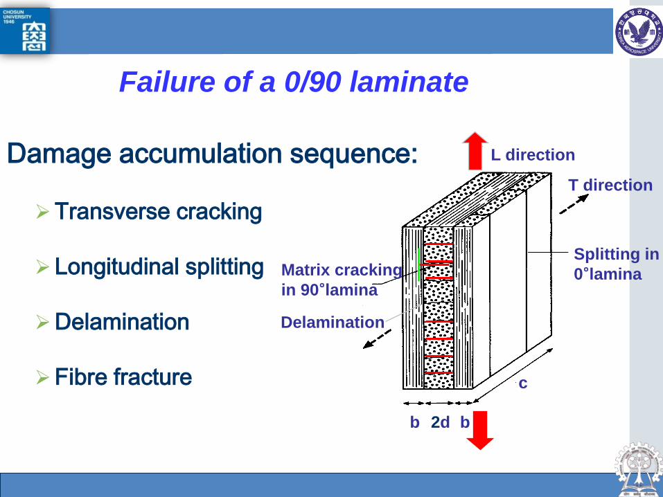
Failure of a 0/90 laminate
L direction
T direction
Splitting in 0°lamina Matrix cracking
in 90°lamina
b b 2d
c
Delamination
Damage accumulation sequence:
Transverse cracking
Longitudinal splitting
Delamination
Fibre fracture

Dept. of Aerospace Engineering, Gas turbine Lab.
Damage Mechanisms under Compression: Fibre microbuckling (Berbinau, Guz, Soutis)
Compression failure of laminates occurs by fibre kinking of 0°-plies, immediately followed by delamination (catastrophic failure).
Kink band
W
x
y
β
φ
z
Kink band in multidirectional T800/924C laminate
Dept. of Aerospace Engineering, Gas turbine Lab.
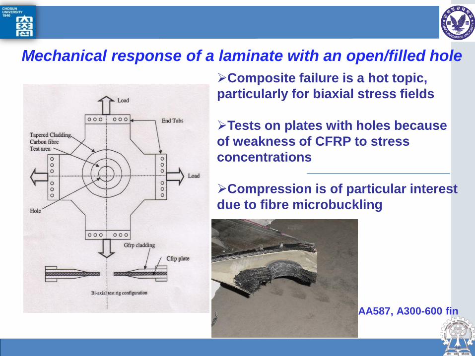
Mechanical response of a laminate with an open/filled hole Composite failure is a hot topic, particularly for biaxial stress fields Tests on plates with holes because of weakness of CFRP to stress concentrations Compression is of particular interest due to fibre microbuckling
AA587, A300-600 fin

Dept. of Aerospace Engineering, Gas turbine Lab.
Compressive response of a composite laminate with a hole
Compressive failure modes: a) Euler buckling b) Sublaminate buckling c) Local damage due to in-plane stresses (fibre microbuckling)
A schematic of a typical CFRP beam structure in an a/c wing

Dept. of Aerospace Engineering, Gas turbine Lab.
Damage Zone Modeling The DZ is treated as an equivalent crack The traction distribution describes the load transfer characteristics of the damage zone Damage propagation is controlled by traction law and applied loading Three experimentally measured phenomena are predicted with a consistent physically-based model: DZ growth, critical length, ultimate failure load
Dept. of Aerospace Engineering, Gas turbine Lab.
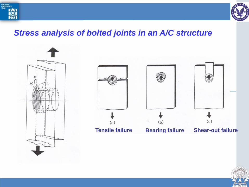
Stress analysis of bolted joints in an A/C structure
Tensile failure Shear-out failure Bearing failure

Dept. of Aerospace Engineering, Gas turbine Lab.
Stress analysis of bolted joints in an a/c structure
Composite wing skin bolted to a metallic L-bracket

Dept. of Aerospace Engineering, Gas turbine Lab.
Matrix Cracking causes degradation of the overall stiffness properties of the laminate
Triggers development of other damage modes, delamination and fibre breakage
Damage Mechanisms under Tension
Dept. of Aerospace Engineering, Gas turbine Lab.
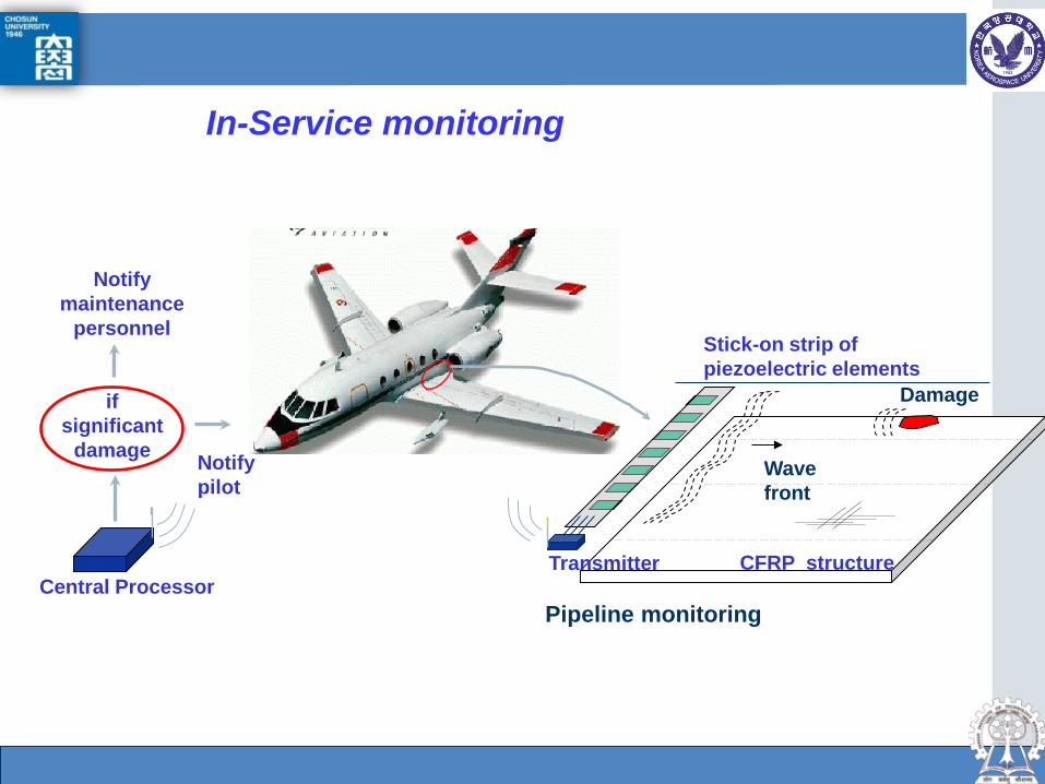
In-Service monitoring
Notify maintenance
personnel
Notify pilot
Central Processor
if significant
damage Wave front
CFRP structure Transmitter
Stick-on strip of piezoelectric elements
Damage
Pipeline monitoring
Dept. of Aerospace Engineering, Gas turbine Lab.
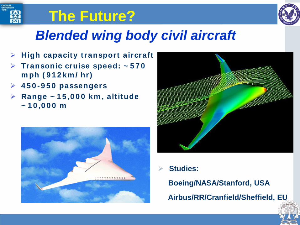
Blended wing body civil aircraft
Studies:
Boeing/NASA/Stanford, USA
Airbus/RR/Cranfield/Sheffield, EU
High capacity transport aircraft Transonic cruise speed: ~570
mph (912km/hr) 450-950 passengers Range ~15,000 km, altitude
~10,000 m
The Future?

Dept. of Aerospace Engineering, Gas turbine Lab.
Why blended wing body? Main drivers for future A/C design: greener, quieter and
safer Current cylindrical body/wing shapes are more than 50
years old, prohibiting substantial improvement BWB aircraft integrates body and wing
Fuselage generates lift, drag↓, emission↓ (e.g. 3 instead of 4x 60,000 lbf thrust engines)
BWB vs B747
Main Challenges Multidisciplinary integrated design Trim and stability at TO, cruise and landing Manufacturing, public acceptance, evacuation,...

Dept. of Aerospace Engineering, Gas turbine Lab.
UAVs spur composites use Unmanned Aerial Vehicles are
viable options for atmospheric research, surveillance, combat and ground attack roles (UCAV)
- X-45A is just 8m long, could drop 2,000-lb munitions Must consider New materials and fabrications
routes Novel structural designs
(Folded/detachable/inflatable wings) SHM & life prognosis Airworthiness
Courtesy of Prof Paul Curtis
F-16
F-117
Boeing X-45A UCAV
66 ft. X-45A – courtesy of Boeing

Dept. of Aerospace Engineering, Gas turbine Lab.
Cost & Manufacture
Reduction of Whole Life Cost (WLC) has become a key driver (cost of purchase, maintenance over service life of platform and disposal) UCAVs are projected to cost up to 65% less
to produce than future manned fighter A/C Most promising manufacturing routes are
Resin Transfer Moulding (RTM) and Resin Infusion under Flexible Tooling (RIFT)
X47A Pegasus– Courtesy of Northrop-Grumman
Rheinmetall Defence Electronics Taifun UCAV

Dept. of Aerospace Engineering, Gas turbine Lab.
Concluding Remarks Composite Materials properties are excellent
But still challenges to be met, especially in fabrication & design Usage of Composites is growing at an increasing rate in Civil
Aerospace Airbus A380, A350 & Boeing ‘Dreamliner’ B787 made major
use of composites In military systems, composites are becoming the 1st choice Future military strike aircraft may be unmanned
Brings materials problems and challenges Balance performance, stealth and cost
Need to reduce cost of all stages through design, materials and fabrication!
MAV
Dept. of Aerospace Engineering, Gas turbine Lab.
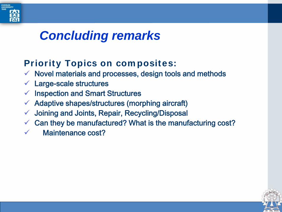
Concluding remarks
Priority Topics on composites: Novel materials and processes, design tools and methods Large-scale structures Inspection and Smart Structures Adaptive shapes/structures (morphing aircraft) Joining and Joints, Repair, Recycling/Disposal Can they be manufactured? What is the manufacturing cost? Maintenance cost?

Dept. of Aerospace Engineering, Gas turbine Lab.
....to the next 100 Years of Flight
Composite Space Structures
INTRODUCTION

Dept. of Aerospace Engineering, Gas turbine Lab.
What are space composite structures? Space Structures are launched from ground to space orbit.
Therefore its size and weight are strictly limited as well as its load and stiffness conditions are severely required in orbit.
In case of satellite structure materials, weight reduction is most important as well as high specific strength and stiffness materials are necessarily required.
Recently satellites trend to become larger and multi-missions, so the lightness should be needed.
Therefore light metal structures have been replaced by advanced composite structures because have better thermal and mechanical properties as well as flexibility of optimal design depending on required load conditions and types.
Part 2 INTRODUCTION
Dept. of Aerospace Engineering, Gas turbine Lab.
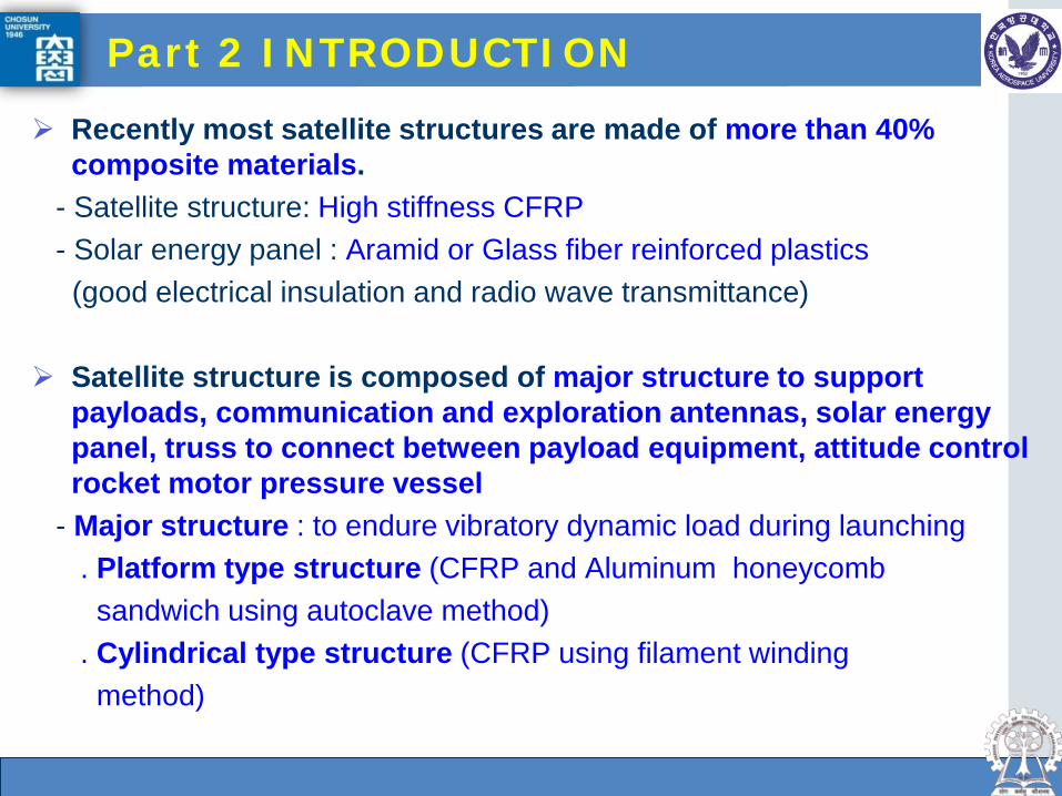
Recently most satellite structures are made of more than 40% composite materials.
- Satellite structure: High stiffness CFRP - Solar energy panel : Aramid or Glass fiber reinforced plastics (good electrical insulation and radio wave transmittance) Satellite structure is composed of major structure to support
payloads, communication and exploration antennas, solar energy panel, truss to connect between payload equipment, attitude control rocket motor pressure vessel
- Major structure : to endure vibratory dynamic load during launching . Platform type structure (CFRP and Aluminum honeycomb sandwich using autoclave method) . Cylindrical type structure (CFRP using filament winding method)
Part 2 INTRODUCTION
Dept. of Aerospace Engineering, Gas turbine Lab.
Part 2 INTRODUCTION
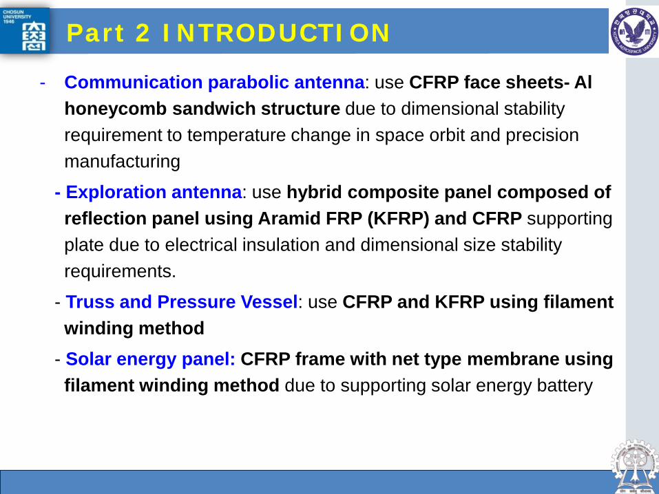
- Communication parabolic antenna: use CFRP face sheets- Al honeycomb sandwich structure due to dimensional stability requirement to temperature change in space orbit and precision manufacturing
- Exploration antenna: use hybrid composite panel composed of reflection panel using Aramid FRP (KFRP) and CFRP supporting plate due to electrical insulation and dimensional size stability requirements.
- Truss and Pressure Vessel: use CFRP and KFRP using filament winding method
- Solar energy panel: CFRP frame with net type membrane using filament winding method due to supporting solar energy battery
Dept. of Aerospace Engineering, Gas turbine Lab.
Part 2 INTRODUCTION
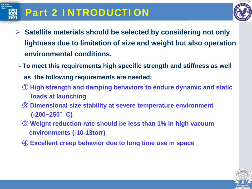
Satellite materials should be selected by considering not only lightness due to limitation of size and weight but also operation environmental conditions.
- To meet this requirements high specific strength and stiffness as well
as the following requirements are needed; ① High strength and damping behaviors to endure dynamic and static loads at launching ② Dimensional size stability at severe temperature environment (-200~250°C) ③ Weight reduction rate should be less than 1% in high vacuum environments (-10-13torr) ④ Excellent creep behavior due to long time use in space
Dept. of Aerospace Engineering, Gas turbine Lab.
Composite materials have lightness such as high specific stiffness and strength as well as good dimensional size stability in severe space environment due to zero or negative thermal expansion coefficient (carbon fiber). Moreover it has design flexibility by tailoring depending on loading direction as well as by selecting different composite materials and various manufacturing methods.
Even though satellite structure weight is about less than 5% of total launching weight, its lightness gives very high economic effectiveness.
Part 2 INTRODUCTION
Dept. of Aerospace Engineering, Gas turbine Lab.
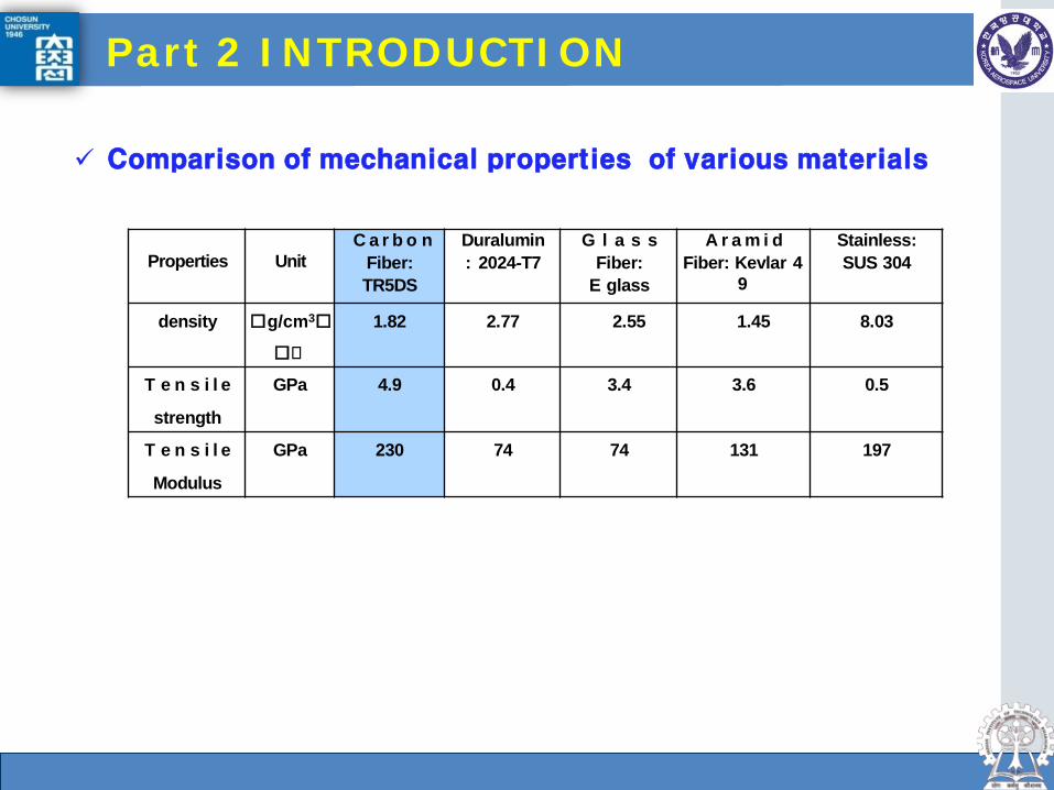
Properties
Unit
C a r b o n Fiber: TR5DS
Duralumin : 2024-T7
G l a s s Fiber:
E glass
A r a m i d Fiber: Kevlar 4
9
Stainless: SUS 304
density g/cm3
1.82 2.77 2.55 1.45 8.03
T e n s i l e
strength
GPa 4.9 0.4 3.4 3.6 0.5
T e n s i l e
Modulus
GPa 230 74 74 131 197
Comparison of mechanical properties of various materials
Part 2 INTRODUCTION
Dept. of Aerospace Engineering, Gas turbine Lab.
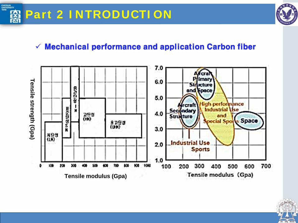
Mechanical performance and application Carbon fiber
Part 2 INTRODUCTION
Tensile modulus (Gpa)
Tensile strength (Gpa)
Dept. of Aerospace Engineering, Gas turbine Lab.
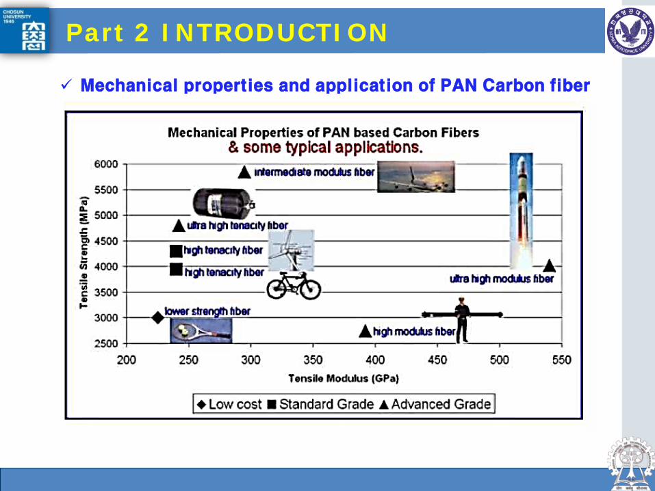
Mechanical properties and application of PAN Carbon fiber
Part 2 INTRODUCTION

Dept. of Aerospace Engineering, Gas turbine Lab.
Part 2 INTRODUCTION
Fig. 3D Control Satellite Structure
Antenna Reflector (CFRP face sheets/Al honeycomb sandwich)
Antenna support (CFRP)
Solar energy panel (CFRP)
Center Fuselage (CFRP filament winding)
Fig. Hubble Satellite Telescope
Solar energy panel (CFRP)

Dept. of Aerospace Engineering, Gas turbine Lab.
Part 2 INTRODUCTION
Fig. 3D Data Transmittance and Tracking Satellite Antenna (CFRP support structure and net type structure)

Dept. of Aerospace Engineering, Gas turbine Lab.
Thank you for your kind attention!