lecture notes: lecture 1 - tu delft ocw · lecture notes: lecture 1.4 this course material is...
TRANSCRIPT
1
Electric cars: Technology Lecture notes: Lecture 1.4
This course material is licensed under a Creative Commons Attibution-
NonCommercial-ShareAlike 4.0 License.
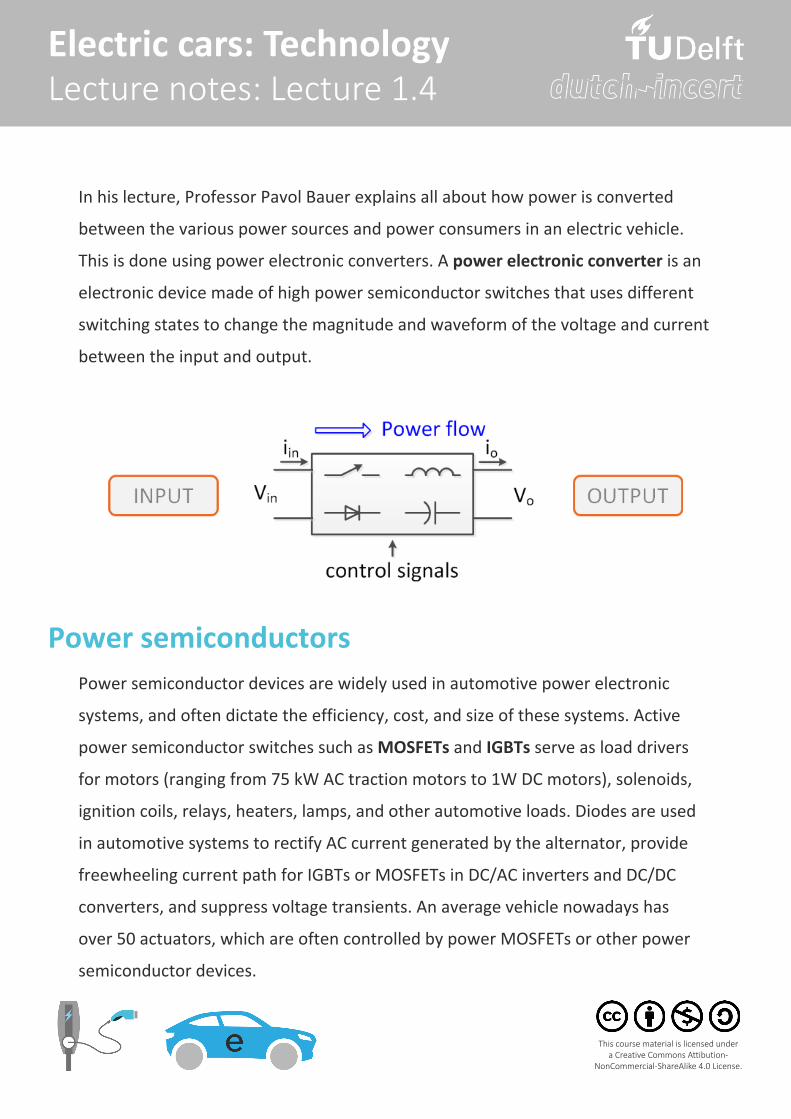
In his lecture, Professor Pavol Bauer explains all about how power is converted
between the various power sources and power consumers in an electric vehicle.
This is done using power electronic converters. A power electronic converter is an
electronic device made of high power semiconductor switches that uses different
switching states to change the magnitude and waveform of the voltage and current
between the input and output.
Power semiconductorsPower semiconductor devices are widely used in automotive power electronic
systems, and often dictate the efficiency, cost, and size of these systems. Active
power semiconductor switches such as MOSFETs and IGBTs serve as load drivers
for motors (ranging from 75 kW AC traction motors to 1W DC motors), solenoids,
ignition coils, relays, heaters, lamps, and other automotive loads. Diodes are used
in automotive systems to rectify AC current generated by the alternator, provide
freewheeling current path for IGBTs or MOSFETs in DC/AC inverters and DC/DC
converters, and suppress voltage transients. An average vehicle nowadays has
over 50 actuators, which are often controlled by power MOSFETs or other power
semiconductor devices.
2
Electric cars: Technology Lecture notes: Lecture 1.4
This course material is licensed under a Creative Commons Attibution-
NonCommercial-ShareAlike 4.0 License.
The voltage ratings of power semiconductor devices are considerably higher
than the specified maximum operating voltage or battery voltage of the power
systems. This is because the voltage rating of automotive power electronics
is mainly determined by the survivability of these devices to the commonly
encountered overvoltage transients in the automotive environment, instead of
just the maximum operating voltages. The transients on the automobile power
supply range from the severe, high energy transients generated by the alternator/
regulator subsystem to the low-level noise generated by the switching of inductive
loads such as ignition coils, relays, solenoids, and DC motors. A typical automotive
electrical system has all of these elements necessary to generate undesirable
transients. It is critical that automotive power semiconductor devices have
sufficient voltage ratings to sustain these electrical transients. The current ratings
of a power semiconductor are mainly related to the energy dissipation and the
junction temperature in the device. The maximum continuous current is usually
defined as the current that the device is capable of conducting continuously
without exceeding the maximum junction temperature.
Commercially available power semiconductor devices can be categorized into
several basic types such as diodes, thyristors, bipolar junction transistors (BJT),
power metal oxide semiconductor field effect transistors (MOSFET), insulated gate
bipolar transistors (IGBT), and gate turn-off thyristors (GTO). In addition, there
are power integrated circuits (ICs) and smart power devices that monolithically
integrate power switching devices with logic/analog control, diagnostic, and
protective functions. Emerging device technology is SiC-based power devices. SiC is
generally considered the most promising semiconductor material to replace silicon
3
Electric cars: Technology Lecture notes: Lecture 1.4
This course material is licensed under a Creative Commons Attibution-
NonCommercial-ShareAlike 4.0 License.
in future power electronic systems.
SiC power devices offer the following benefits over their silicon counterparts:
• The higher breakdown electric field strength of SiC allows a much thinner
drift region and thus a much smaller specific on-resistance of SiC devices than
their silicon counterparts.
• The low on-resistance of SiC devices for a voltage rating of 600–2000V allows
the use of majority-carrier devices like MOSFET and Schottky diodes rather
than minority-carrier devices such as IGBT and PiN diodes. This results in
a much reduced switching losses and absence of charge storage effect.
Lower switching losses will further allow higher switching frequency and
subsequently smaller and less expensive passive components such as filter
inductors and capacitors.
• The larger bandgap results in higher intrinsic carrier concentration and higher
operating junction temperature. In principle, SiC devices could operate at
a junction temperature as high as 300oC, as compared to 150oC maximum
junction temperature of silicon devices. The increased operating temperature
will reduce the weight, volume, cost, and complexity of thermal management
systems.
• The very high thermal conductivity of SiC reduces the thermal resistance of
the device die.
• The higher bandgap also results in much higher Schottky metal-
semiconductor barrier height as compared to Si. This leads to extremely low
leakage currents even at elevated junction temperatures due to reduced
4
Electric cars: Technology Lecture notes: Lecture 1.4
This course material is licensed under a Creative Commons Attibution-
NonCommercial-ShareAlike 4.0 License.
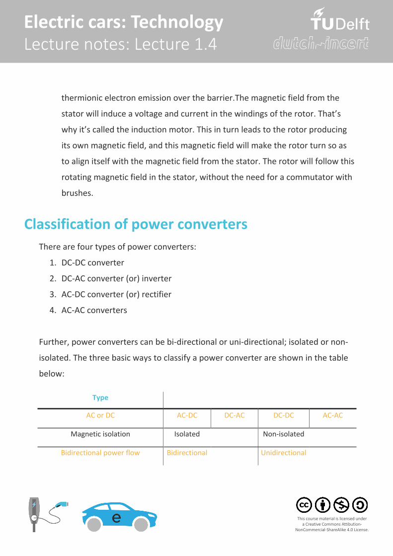
Type
AC or DC AC-DC DC-AC DC-DC AC-AC
Magnetic isolation Isolated Non-isolated
Bidirectional power flow Bidirectional Unidirectional
There are four types of power converters:
1. DC-DC converter
2. DC-AC converter (or) inverter
3. AC-DC converter (or) rectifier
4. AC-AC converters
Further, power converters can be bi-directional or uni-directional; isolated or non-
isolated. The three basic ways to classify a power converter are shown in the table
below:
Classification of power converters
thermionic electron emission over the barrier.The magnetic field from the
stator will induce a voltage and current in the windings of the rotor. That’s
why it’s called the induction motor. This in turn leads to the rotor producing
its own magnetic field, and this magnetic field will make the rotor turn so as
to align itself with the magnetic field from the stator. The rotor will follow this
rotating magnetic field in the stator, without the need for a commutator with
brushes.
5
Electric cars: Technology Lecture notes: Lecture 1.4
This course material is licensed under a Creative Commons Attibution-
NonCommercial-ShareAlike 4.0 License.
Isolation is necessary between the EV battery and the grid for safety reasons. Hence
the AC/DC on-board charger and/or the DC/DC battery converter must be isolated.
Depending on the EV, one or both of these converters are isolated and different
power converter topologies are used.
Isolation between EV battery and grid
In any power converter, energy is always conserved. Hence, the input and output
power can be related based on the losses in the power converter as,
Pout = Pin - Ploss
Pin = Vin * Iin
Pout = Vout * Iout
η = Pout / Pin * 100
Where:
Pout, Pin, Ploss are the output and input power of the power converter
Ploss is the losses in the power converter
Vin, Iin are the input voltage and current of the power converter
Vout, Iout are the output voltage and current of the power converter
Conservation of energy
6
Electric cars: Technology Lecture notes: Lecture 1.4
This course material is licensed under a Creative Commons Attibution-
NonCommercial-ShareAlike 4.0 License.
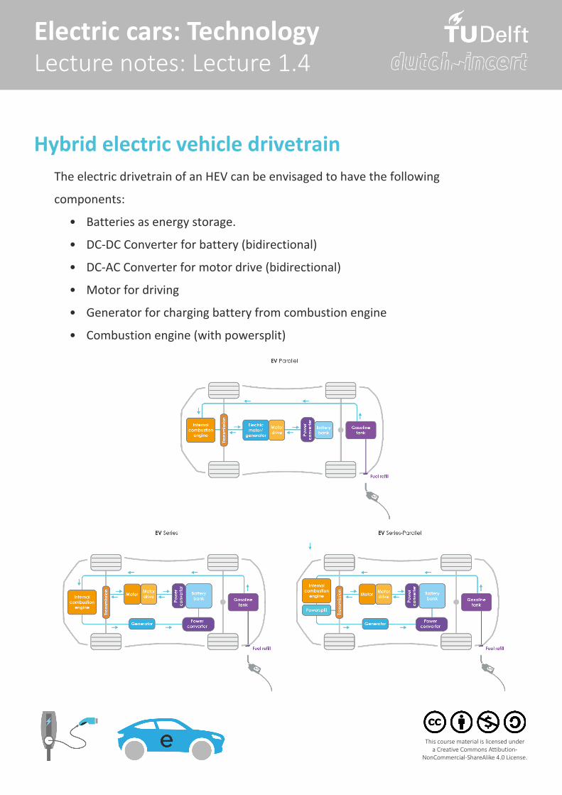
Hybrid electric vehicle drivetrainThe electric drivetrain of an HEV can be envisaged to have the following
components:
• Batteries as energy storage.
• DC-DC Converter for battery (bidirectional)
• DC-AC Converter for motor drive (bidirectional)
• Motor for driving
• Generator for charging battery from combustion engine
• Combustion engine (with powersplit)
7
Electric cars: Technology Lecture notes: Lecture 1.4
This course material is licensed under a Creative Commons Attibution-
NonCommercial-ShareAlike 4.0 License.
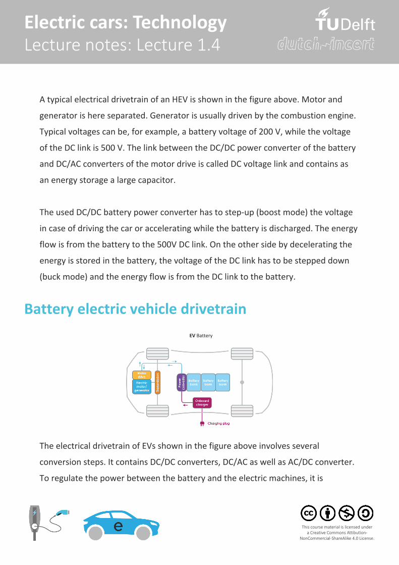
A typical electrical drivetrain of an HEV is shown in the figure above. Motor and
generator is here separated. Generator is usually driven by the combustion engine.
Typical voltages can be, for example, a battery voltage of 200 V, while the voltage
of the DC link is 500 V. The link between the DC/DC power converter of the battery
and DC/AC converters of the motor drive is called DC voltage link and contains as
an energy storage a large capacitor.
The used DC/DC battery power converter has to step-up (boost mode) the voltage
in case of driving the car or accelerating while the battery is discharged. The energy
flow is from the battery to the 500V DC link. On the other side by decelerating the
energy is stored in the battery, the voltage of the DC link has to be stepped down
(buck mode) and the energy flow is from the DC link to the battery.
Battery electric vehicle drivetrain
The electrical drivetrain of EVs shown in the figure above involves several
conversion steps. It contains DC/DC converters, DC/AC as well as AC/DC converter.
To regulate the power between the battery and the electric machines, it is
EV Battery
8
Electric cars: Technology Lecture notes: Lecture 1.4
This course material is licensed under a Creative Commons Attibution-
NonCommercial-ShareAlike 4.0 License.
necessary to use a power converter device. The battery is a DC supply source,
delivering current at a particular voltage. Power flowing into the battery must be
processed to ensure it is being delivered at the correct voltage. Similarly, the power
delivered by the battery must be processed to ensure the electric machine can
provide the optimum power to propel the vehicle.
The precise functionality of power converters depends on many factors, but
primarily on the type of electric machine being used and the maximum power
delivery. Converters are made of high power fast-acting semiconductor devices,
which act as high speed switches. Different switching states alter the input voltage
and current through the use of capacitive and inductive elements. The result is an
output voltage and current, which is at a different level to the input.
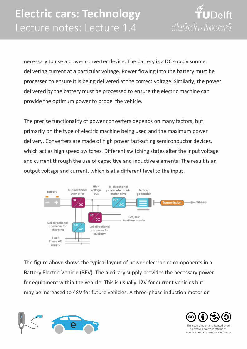
The figure above shows the typical layout of power electronics components in a
Battery Electric Vehicle (BEV). The auxiliary supply provides the necessary power
for equipment within the vehicle. This is usually 12V for current vehicles but
may be increased to 48V for future vehicles. A three-phase induction motor or
9
Electric cars: Technology Lecture notes: Lecture 1.4
This course material is licensed under a Creative Commons Attibution-
NonCommercial-ShareAlike 4.0 License.
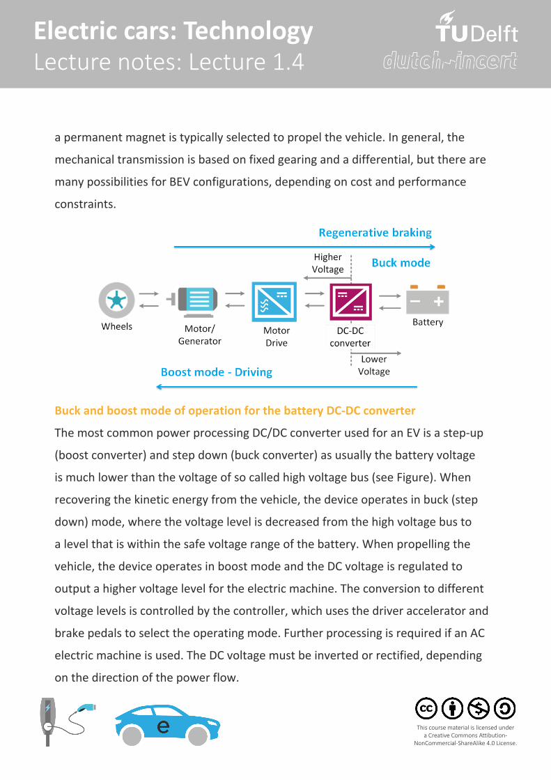
a permanent magnet is typically selected to propel the vehicle. In general, the
mechanical transmission is based on fixed gearing and a differential, but there are
many possibilities for BEV configurations, depending on cost and performance
constraints.
Buck and boost mode of operation for the battery DC-DC converter
The most common power processing DC/DC converter used for an EV is a step-up
(boost converter) and step down (buck converter) as usually the battery voltage
is much lower than the voltage of so called high voltage bus (see Figure). When
recovering the kinetic energy from the vehicle, the device operates in buck (step
down) mode, where the voltage level is decreased from the high voltage bus to
a level that is within the safe voltage range of the battery. When propelling the
vehicle, the device operates in boost mode and the DC voltage is regulated to
output a higher voltage level for the electric machine. The conversion to different
voltage levels is controlled by the controller, which uses the driver accelerator and
brake pedals to select the operating mode. Further processing is required if an AC
electric machine is used. The DC voltage must be inverted or rectified, depending
on the direction of the power flow.
10
Electric cars: Technology Lecture notes: Lecture 1.4
This course material is licensed under a Creative Commons Attibution-
NonCommercial-ShareAlike 4.0 License.
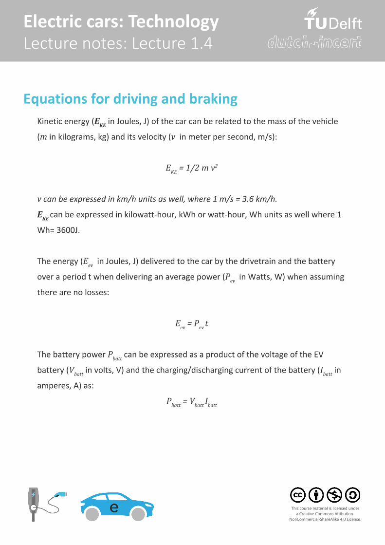
Equations for driving and brakingKinetic energy (EKE in Joules, J) of the car can be related to the mass of the vehicle
(m in kilograms, kg) and its velocity (v in meter per second, m/s):
EKE = 1/2 m v2
v can be expressed in km/h units as well, where 1 m/s = 3.6 km/h.
EKE can be expressed in kilowatt-hour, kWh or watt-hour, Wh units as well where 1
Wh= 3600J.
The energy (Eev in Joules, J) delivered to the car by the drivetrain and the battery
over a period t when delivering an average power (Pev in Watts, W) when assuming
there are no losses:
Eev = Pev t
The battery power Pbatt can be expressed as a product of the voltage of the EV
battery (Vbatt in volts, V) and the charging/discharging current of the battery (Ibatt in
amperes, A) as:
Pbatt = Vbatt Ibatt
11
Electric cars: Technology Lecture notes: Lecture 1.4
This course material is licensed under a Creative Commons Attibution-
NonCommercial-ShareAlike 4.0 License.
Based on the EV battery power, the corresponding C-rate of the battery pack can
be estimated.
C-rate is the ratio of the battery power (Pev in kilowatts, kW) to the nominal energy
capacity of the battery (Enom in kilowatt-hour) in kWh. As the charging current
increases, so does the C-rate:
C-rate = Pev / Enom
An alternate definition of C-rate is its the ratio of the battery charging/discharging
current (Ibatt in amperes, A) to the nominal ampere hour of the battery (Qnom in
ampere-hours, Ah):
C-rate = Ibatt / Qnom