lecture notes on concrete technology iii b. e … technology.pdf · lecture notes on concrete...
TRANSCRIPT

LECTURE NOTES
ON
CONCRETE TECHNOLOGY
III B. E VI semester (R2013)
DEPARTMENT OF CIVIL ENGINEERING

UNIT- 1
CONSTITUENT MATERIALS
1.1 Portland Cement
Concrete is made by portland cement, water and aggregates. Portland cement is a hydraulic cement that
hardens in water to form a water-resistant compound. The hydration products act as binder to hold the
aggregates together to form concrete. The name portland cement comes from the fact that the colour and
quality of the resulting concrete are similar to Portland stone, a kind of limestone found in England.
1.1.1 Manufacture of Portland cement
Portland cement is made by blending the appropriate mixture of limestone and clay or shale
together and by heating them at 1450oC in a rotary kiln. The sequence of operations is shown in
following figure. The preliminary steps are a variety of blending and crushing operations. The raw feed must have a uniform composition and be a size fine enough so that reactions among the components can complete in the kiln. Subsequently, the burned clinker is ground with gypsum to form the familiar grey powder known as Portland cement.

The raw materials used for manufacturing Portland cement are limestone, clay and Iron ore. a)
Limestone (CaCO3) is mainly providing calcium in the form of calcium oxide (CaO)
CaCO3 (1000oC) → CaO + CO2
b) Clay is mainly providing silicates (SiO2) together with small amounts of Al2O3 + Fe2O3
Clay (1450oC) → SiO2 + Al2O3 + Fe2O3 + H2O
c) Iron ore and Bauxite are providing additional aluminium and iron oxide (Fe2O3) which help the
formation of calcium silicates at low temperature. They are incorporated into the raw mix.
Limestone 3 CaOoSiO2
High temperature 2 CaOoSiO2
Clay
CaOoAl2O3 (1,450
oC) 3
Iron Ore, Bauxite 4 CaOoAl2O3
oFe2O3
d) The clinker is pulverized to small sizes (< 75 μm). 3-5% of gypsum (calcium sulphate) is added to control setting and hardening.
The majority particle size of cement is from 2 to 50 μm. A plot of typical particle size distribution is given below. (Note: “Blaine” refers to a test to measure particle size in terms of surface area/mass)

1.1.2 Chemical composition
a) Abbreviation:
CaO = C, SiO2 = S, Al2O3 = A; Fe2O3 =F, Ca(OH)2 = CH,
H2O = H, SO3 = S (sulphur trioxide)
Thus we can write 3 CaO = C3 and 2 CaOoSiO2 = C2S.
b) Major compounds:
Compound Oxide colour Common name Weight percentage
composition
Tricalcium
Silicate C3S white Alite 50%
Dicalcium
Silicate C2S white Belite 25%
Tricalcium
Aluminate C3A white/grey --- 12%
Tetracalcium
Aluminoferrite C4AF black Ferrite 8% Since the primary constituents of Portland cement are calcium silicate, we can define Portland cement as a
material which combine CaO SiO2 in such a proportion that the resulting calcium silicate will react with water at room temperature and under normal pressure.
c) Minor components of Portland cement
The most important minor components are gypsum, MgO, and alkali sulphates.
Gypsum (2CaSO4o2H2O) is an important component added to avoid flash set.
Alkalies (MgO, Na2O, K2O) can increase pH value up to 13.5 which is good for reinforcing steel
protection. However, for some aggregates, such a high alkaline environment can cause alkali aggregate
reaction problem.

1.1.3 Hydration
The setting and hardening of concrete are the result of chemical and physical processes that take place
between Portland cement and water, i.e. hydration. To understand the properties and behaviour of cement
and concrete some knowledge of the chemistry of hydration is necessary.
A) Hydration reactions of pure cement compounds
The chemical reactions describing the hydration of the cement are complex. One approach is to study the
hydration of the individual compounds separately. This assumes that the hydration of each compound
takes place independently of the others.
I. Calcium silicates
Hydration of the two calcium silicates gives similar chemical products, differing only in the amount of
calcium hydroxide formed, the heat released, and reaction rate.
2 C3S + 7 H → C3S2H4 + 3 CH 2 C2S + 5 H → C3S2H4 + CH
The principal hydration product is C3S2H4, calcium silicate hydrate, or C -S-H (non-stoichiometric). This
product is not a well-defined compound. The formula C3S2H4 is only an approximate description. It has amorphous structure making up of poorly organized layers and is called glue gel binder. C-S-H is believed
to be the material governing concrete strength. Another product is CH - Ca(OH)2, calcium hydroxide. This product is a hexagonal crystal often forming stacks of plates. CH can bring the pH value to over 12 and it is good for corrosion protection of steel.
II. Tricalcium aluminate
Without gypsum, C3A reacts very rapidly with water:
C3A + 6 H → C3AH6
The reaction is so fast that it results in flash set, which is the immediate stiffening after mixing, making
proper placing, compacting and finishing impossible.
With gypsum, the primary initial reaction of C3A with water is :
C3A + 3 (C S H2) + 26 H → C6A S 3H32
The 6 -calcium aluminate trisulfate-32-hydrate is usually called ettringite. The formation of ettringite
slows down the hydration of C3A by creating a diffusion barrier around C3A. Flash set is thus avoided. Even with gypsum, the formation of ettringite occurs faster than the hydration of the calcium silicates. It therefore contributes to the initial stiffening, setting and early strength development. In normal cement mixes, the
ettringite is not stable and will further react to form monosulphate (C4A S H18).

B) Kinetics and Reactivities
The rate of hydration during the first few days is in the order of C3A > C3S > C4AF >C2S.
Their reactivities
can be observed in the following
figures.

C) Calorimetric curve of Portland cement
A typical calorimetric curve of Portland cement is shown in the following figure. The second heat peaks
of both C3S and C3A can generally be distinguished, although their order of occurrence can be reversed.
From the figure, five stages can be easily identified. Since C3S is a dominating component in cement, the
five stages above can be explained using the reaction process of C3S by the following table.

On first contact with water, calcium ions and hydroxide ions are rapidly released from the surface of
each C3S grain; the pH values rises to over 12 within a few minutes. This hydrolysis slows down quickly but continues throughout the induction period. The induction (dormant) period is caused by the need to achieve a certain concentration of ions in solution before crystal nuclei are formed for the hydration products to grow from. At the end of dormant period, CH starts to crystallize from solution with the
concomitant formation of C-S-H and the reaction of C3 S again proceeds rapidly (the third stage begin).
CH crystallizes from solution, while C-S-H develops from the surface of C3 S and forms a coating covering the grain. As hydration continues, the thickness of the hydrate layer increases and forms a
barrier through which water must flow to reach the unhydrated C3S and through which ions must diffuse to reach the growing crystals. Eventually, movement through the C-S-H layer determines the rate of reaction. The process becomes diffusion controlled.
D) Setting and Hydration
Initial set of cement corresponds closely to the end of the induction period, 2-4 hours after mixing. Initial
set indicates the beginning of forming of gel or beginning of solidification. It represents approximately
the time at which fresh concrete can no longer be properly mixed, placed or compacted. The final set
occurs 5-10 hours after mixing, within the acceleration period. It represents approximately the time after
which strength develops at a significant rate.
In practice, initial and final set are determined in a rather arbitrary manner with the penetration test.
While the determination of initial and the final set has engineering significance, there is no fundamental change in hydration process for these two different set conditions.
1.1.4 Types of Portland cements
According to ASTM standard, there are five basic types of Portland cement.
Type I Regular cement, general use, called OPC
Type II Moderate sulphate resistance, moderate heat of hydration, C3A < 7%
Type III With increased amount of C3S, High early strength
Type IV Low heat
Type V High sulphate resistance
(Note: sulphates can react with C4A S H18 to from an expansive product. By reducing the C3A content,
there will be less C4A S H18 formed in the hardened paste)

Their typical chemical composition is given in the following table:
From the above table, we can evaluate the behaviour of each type of cement and provide the standard in
selecting different cement types. The following figures show the strength and temperature rise for the
different types of cement.

These graphs provide the basic justification in selecting the cement for engineering application. For instance, for massive concrete structure, hydration heat is an important consideration because excessive
temperature increase (to above 50-60oC) will cause expansion and cracking. Hence, type IV cement
should be the first candidate and Type III should not be used. For a foundation exposed to groundwater with high concentration of sulphates, high sulphate resistance is needed. Thus, type V should be selected. If high early strength is needed, type III will be the best choice. But, generally, type I is the most popular cement used for civil engineering.
1.1.5 Porosity of hardened cement paste and the role of water
Knowledge of porosity is very useful since porosity has a strong influence on strength and durability. In
hardened cement paste, there are several types of porosity, trapped or entrained air (0.1 to several mm in
size), capillary pores (0.01 to a few microns) existing in the space between hydration products, and gel
pores (several nanometres or below) within the layered structure of the C-S-H. The capillary pores have a
large effect on the strength and permeability of the hardened paste itself. Of course, the presence of air
bubbles can also affect strength.
From experiments, the porosity within the gel for all normally hydrated cements is the same, with a value
of 0.26. The total volume of hydration products (cement gel) is given by
Vg = 0.68α cm3/g of original cement
Where, α represents the degree of hydration.

The capillary porosity can be calculated by
Pc = (w/c) −0.36α cm3/g of original cement
Where, w is the original weight of water and c is the weight of cement and w/c is the water-cement ratio. It
can be seen that with increase of w/c, the capillary pores increase.
The gel / space ratio (X) is defined as
X =
volume of gel (including gel pores)
volume of gel + volume of capillary pores
= 0.68α
0.32α+ w/c
The minimum w/c ratio for complete hydration is usually assumed to be 0.36 to 0.42. It should be
indicated that complete hydration is not essential to attain a high ultimate strength. For pastes of low w/c
ratio, residual unhydrated cement will remain.
To satisfy workability requirements, the water added in the mix is usually more than that needed for the
chemical reaction. Part of the water is used up in the chemical reaction. The remaining is either held by the
C -S-H gel or stored in the capillary pore. Most capillary water is free water (far away from the pore
surface). On drying, they will be removed, but the loss of free water has little effect on concrete. Loss of
adsorbed water on surfaces and those in the gel will, however, lead to shrinkage. Movement of adsorbed
and gel water under load is a cause of creeping in concrete
1.1.6 Basic tests of Portland cement
a) Fineness (= surface area / weight): This test determines the average size
of cement grains. The typical value of fineness is 350 m2 / kg.
Fineness controls the rate and completeness of hydration. The finer a cement,
the more rapidly it reacts, the higher the rate of heat evolution and the higher the early strength.
Fineness (m2 / kg)
I III V
350 450 350
f’c 1-day (MPa) 6.9 13.8 6.2
b) Normal consistency test: This test is to determine the water required to
achieve a desired plasticity state (called normal consistency) of cement paste.
It is obtained with the Vicat apparatus by measuring the penetration of a
loaded needle.
c) Time of setting: This test is to determine the time required for cement paste
to harden. Initial set cannot be too early due to the requirement of mixing,

conveying, placing and casting. Final set cannot be too late owing to the requirement of strength development. Time of setting is measured by Vicat apparatus. Initial setting time is defined as the time at which the needle penetrates 25 mm into cement paste. Final setting time is the time at which the needle does not sink visibly into the cement paste.
d) Soundness: Unsoundness in cement paste refers to excessive volume change after setting. Unsoundness in cement is caused by the slow hydration of MgO or free lime. Their reactions are MgO +H2O = Mg(OH)2 and CaO + H2O = Ca(OH)2. Another factor that can cause unsoundness is the delayed formation of ettringite after cement and concrete have hardened. The pressure from crystal growth will lead to cracking and damage. The soundness of the cement must be tested by accelerated methods. An example is the Le Chatelier test (BS 4550) . This test is to measure the potential for volumetric change of cement paste. Another method is called Autoclave Expansion test (ASTM C151) which use an autoclave to increase the temperature to accelerate the process.
e) Strength: The strength of cement is measured on mortar specimens made of cement and standard sand (silica). Compression test is carried out on a 2" cube with S/C ratio of 2.75:1 and w/c ratio of 0.485 for Portland cements. The specimens are tested wet, using a loading rate at which the specimen will fail in 20 to 80 s. The direct tensile test is carried out on a specimen shaped like a dumbbell. The load is applied through specifically designed grips. Flexural strength is measured on a 40 x 40 x 160 mm prism beam test under a centre-point bending.
f) Heat of hydration test. (BS 4550: Part 3: Section 3.8 and ASTM C186). Cement hydration is a
heat releasing process. The heat of hydration is usually defined as the amount of heat evolved during
the setting and hardening at a given temperature measured in J/g. The experiment is called heat of
solution method. Basically, the heat of solution of dry cement is compared to the heats of solution of
separate portion of the cement that have been partially hydrated for 7 and 28 days. The heat of
hydration is then the difference between the heats of solution of dry and partially hydrated cements
for the appropriate hydration period. This test is usually done on Type II and IV cements only,
because they are used when heat of hydration is an important concern.
Excessive heating may lead to cracking in massive concrete construction.
g) Other experiments. Including sulphate expansion and air content of mortar.
h) Cement S. G and U. W.: The S.G. for most types of cements is 3.15, and UW is 1000-1600 kg/m3.
1.2 Aggregates
Aggregates are defined as inert, granular, and inorganic materials that normally consist of stone or stone-
like solids. Aggregates can be used alone (in road bases and various types of fill) or can be used with
cementing materials (such as Portland cement or asphalt cement) to form composite materials or concrete.
The most popular use of aggregates is to form Portland cement concrete. Approximately three-fourths of the
volume of Portland cement concrete is occupied by aggregate. It is inevitable that a constituent occupying
such a large percentage of the mass should have an important effect on the properties of both the fresh and
hardened products. As another important application, aggregates are used in asphalt cement concrete in
which they occupy 90% or more of the total volume. Once again, aggregates can largely influence the
composite properties due to its large volume fraction.

1.2.1 Classification of Aggregate
Aggregates can be divided into several categories according to different criteria.
a) In accordance with size:
Coarse aggregate: Aggregates predominately retained on the No. 4 (4.75 mm) sieve. For mass concrete, the maximum size can be as large as 150 mm.
Fine aggregate (sand): Aggregates passing No.4 (4.75 mm) sieve and predominately retained on the No. 200 (75 μm) sieve.
b) In accordance with sources:
Natural aggregates: This kind of aggregate is taken from natural deposits without changing their nature during the process of production such as crushing and grinding. Some examples in this category are sand, crushed limestone, and gravel.
Manufactured (synthetic) aggregates: This is a kind of man-made materials produced as a main product or an industrial by-product. Some examples are blast furnace slag, lightweight aggregate (e.g. expanded perlite), and heavy weight aggregates (e.g. iron ore or crushed steel).
c) In accordance with unit weight:
Light weight aggregate: The unit weight of aggregate is less than 1120kg/m3. The corresponding
concrete has a bulk density less than 1800kg/m3. (cinder, blast-furnace slag, volcanic pumice).
Normal weight aggregate: The aggregate has unit weight of 1520-1680kg/m3. The concrete made with
this type of aggregate has a bulk density of 2300-2400 kg/m3.
Heavy weight aggregate: The unit weight is greater than 2100 kg/m3. The bulk density of the
corresponding concrete is greater than 3200 kg/m3. A typical example is magnesite limonite, a heavy iron
ore. Heavy weight concrete is used in special structures such as radiation shields.
d)In accordance with origin:

Igneous rock Aggregate:
• Hard, tough and dense.
• Massive structures: crystalline, glassy or both depending on the rate at which they are cooled during formation.
• Acidic or basic: percentage of silica content.
• Light or dark coloured.
• Chemically active: react with alkalis.
Sedimentary rock Aggregates:
• Igneous or metamorphic rocks subjected to weathering agencies.

• Decompose, fragmentise, transport and deposit deep beneath ocean bed are cemented together.
• Can be flaky.
• Range from soft-hard, porous-dense, light-heavy.
• Suitability decided by: degree of consolidation, type of cementation, thickness of layer and contamination.
Metamorphic rock Aggregate:
• Rocks subjected to high temperature and pressure.
• Economic factor into consideration.
• Least overall expense.

e) Particle shape:
• Rounded Aggregate: Good workability, low water demand, poor bond
• Angular Aggregate: Increased water demand, good bond
• Flaky Aggregate: Aggregate stacks give workability problems
• Elongated Aggregate: May lack cohesion and require increased fines

• Irregular Aggregate: Fair workability, low water demand. Irregular shape with rounded edges.
• Angularity number (IS:2386-Part 1-1963):
The concept of angularity number was suggested by Shergold.
It gives a qualitative representation of shape of aggregate.
In angularity number test, a quantity of single sized aggregate is filled into metal cylinder of 3 litres capacity. Then the aggregate is compacted in a standard manner and the percentage of void found out.
If the void content of the aggregate is 33% the angularity of such aggregate is considered 0.
If the void is 44%, the angularity number of such aggregate is considered 11.
• Importance of Angularity Number:
The normal aggregate which are suitable for making concrete may have angularity
number anything from 0 to 11.
Angularity number 0 represents the most practicable rounded aggregate Angularity number 11 indicates the most angular aggregate that could be used for
making concrete.
• Angularity Index:
Suggested by Murdock for expressing shape of aggregate.
Angularity index = fA = + 1.0 Where, fH is the angularity number.
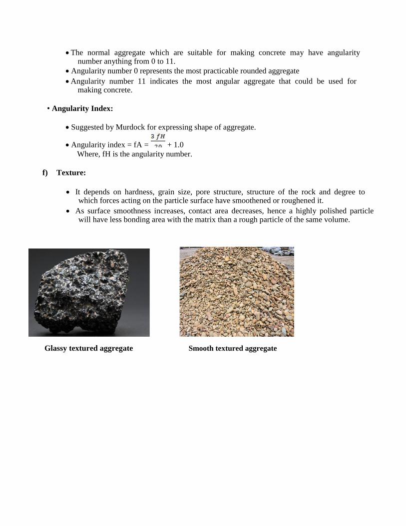
f) Texture:
It depends on hardness, grain size, pore structure, structure of the rock and degree to which forces acting on the particle surface have smoothened or roughened it.
As surface smoothness increases, contact area decreases, hence a highly polished particle will have less bonding area with the matrix than a rough particle of the same volume.
Glassy textured aggregate Smooth textured aggregate

Granular textured aggregate Crystalline textured aggregate
Porous textured aggregate
1.2.2 Strength of Aggregates
• When the cement paste is of good quality & its bond with the aggregate is satisfactory, then the mechanical properties of rock or aggregate will influence the strength of concrete.
• The test for strength of aggregate is required to be made in the following situations: i. For production of high strength & ultra -high strength concrete.
ii. When contemplating to use aggregates manufacture from weathered rocks.
iii. Aggregates manufactured by industrial process.

UNIT 2 CHEMICAL AND MINERAL ADMIXTURES Admixtures Admixtures are those ingredients in concrete other than portland cement, water, and aggregates that are added to the mixture immediately before or during mixing.
Admixtures can be classified by function as follows:
1. Air-entraining admixtures
2. Water-reducing admixtures 3. Plasticizers
4. Accelerating admixtures 5. Retarding admixtures
6. Hydration-control admixtures 7. Corrosion inhibitors
8. Shrinkage reducers 9. Alkali-silica reactivity inhibitors
10. Colouring admixtures 11. Miscellaneous admixtures such as workability, bonding, dampproofing, permeability reducing,
grouting, gas forming, anti-washout, foaming, and pumping admixtures.
Concrete should be workable, finishable, strong, durable, watertight, and wear resistant. These qualities can often be obtained easily and economically by the selection of suitable materials rather than by resorting to admixtures (except air-entraining admixtures when needed).
The major reasons for using admixtures
1. To reduce the cost of concrete construction 2. To achieve certain properties in concrete more effectively than by other means 3. To maintain the quality of concrete during the stages of mixing, transporting, placing, and curing
in adverse weather conditions 4. To overcome certain emergencies during concreting operations
Classification of admixtures


UNIT 3
PROPORTIONING OF CONCRETE MIX
4.1 INTRODUCTION
The common method of expressing the proportions of ingredients of a concrete mix is in the terms of
parts or ratios of cement, fine and coarse aggregates. For e.g., a concrete mix of proportions 1:2:4
means that cement, fine and coarse aggregate are in the ratio 1:2:4 or the mix contains one part of
cement, two parts of fine aggregate and four parts of coarse aggregate. The proportions are either by
volume or by mass. The water-cement ratio is usually expressed in mass.
4.2 Factors to be considered for mix design
The grade designation giving the characteristic strength requirement of concrete.
The type of cement influences the rate of development of compressive strength of concrete.
Maximum nominal size of aggregates to be used in concrete may be as large as possible within the limits prescribed by IS 456:2000.
The cement content is to be limited from shrinkage, cracking and creep.
The workability of concrete for satisfactory placing and compaction is related to the size and shape of section, quantity and spacing of reinforcement and technique used for transportation, placing and compaction.
4.3 Procedure for Concrete Mix Design – IS456:2000
1. Determine the mean target strength ft from the specified characteristic compressive
strength at 28-day fck and the level of quality control.
ft = fck + 1.65 S
Where, S is the standard deviation obtained from the Table of approximate contents given after the design mix.
2. Obtain the water cement ratio for the desired mean target using the empirical relationship
between compressive strength and water cement ratio so chosen is checked against the
limiting water cement ratio. The water cement ratio so chosen is checked against the limiting water cement ratio for the requirements of durability given in table and adopts
the lower of the two values.
3. Estimate the amount of entrapped air for maximum nominal size of the aggregate from the table.
4. Select the water content, for the required workability and maximum size of aggregates
(for aggregates in saturated surface dry condition) from table.
5. Determine the percentage of fine aggregate in total aggregate by absolute volume from table for the concrete using crushed coarse aggregate.

6. Adjust the values of water content and percentage of sand as provided in the table for any difference in workability, water cement ratio, grading of fine aggregate and for rounded aggregate the values are given in table.
7. Calculate the cement content form the water-cement ratio and the final water content as
arrived after adjustment. Check the cement against the minimum cement content from the requirements of the durability, and greater of the two values is adopted.
8. From the quantities of water and cement per unit volume of concrete and the percentage of
sand already determined in steps 6 and 7 above, calculate the content of coarse and fine aggregates per unit volume of concrete from the following relations:
Where, V = absolute volume of concrete = gross volume (1m3) minus the volume
of entrapped air
Sc = specific gravity of cement
W = Mass of water per cubic metre of concrete, kg
C = mass of cement per cubic metre of concrete, kg
p = ratio of fine aggregate to total aggregate by absolute volume
fa, Ca = total masses of fine and coarse aggregates, per cubic metre of concrete, respectively, kg, and
Sfa, Sca = specific gravities of saturated surface dry fine and coarse aggregates, respectively
9. Determine the concrete mix proportions for the first trial mix.
10. Prepare the concrete using the calculated proportions and cast three cubes of 150 mm size and test them wet after 28-days moist curing and check for the strength.
11. Prepare trial mixes with suitable adjustments till the final mix proportions are arrived at.
4.4 CONCRETE MIX DESIGN EXAMPLE – M50 GRADE CONCRETE
Grade Designation = M-50
Type of cement = O.P.C-43 grade Brand of cement = Vikram ( Grasim )
Admixture = Sika [Sikament 170 ( H ) ] Fine Aggregate = Zone-II
Sp. Gravity
Cement = 3.15
Fine Aggregate = 2.61 Coarse Aggregate (20mm) = 2.65
Coarse Aggregate (10mm) = 2.66

Minimum Cement (As per contract) =400 kg / m3 Maximum water cement ratio (As per contract) = 0.45
Mix Calculation: –
1. Target Mean Strength = 50 + (5 X 1.65 ) = 58.25 Mpa 2. Selection of water cement ratio:-
Assume water cement ratio = 0.35
3. Calculation of water: –
Approximate water content for 20mm max. Size of aggregate = 180 kg /m3 (As per Table
No. 5, IS : 10262 ). As plasticizer is proposed we can reduce water content by 20%.
Now water content = 180 X 0.8 = 144 kg /m3
4. Calculation of cement content:-
Water cement ratio = 0.35 Water content per cum of concrete = 144 kg
Cement content = 144/0.35 = 411.4 kg / m3
Say cement content = 412 kg / m3 (As per contract Minimum cement content 400 kg /
m3) Hence O.K.
5. Calculation for C.A. & F.A.: –
Volume of concrete = 1 m3
Volume of cement = 412 / (3.15 X 1000) = 0.1308
m3 Volume of water = 144 / (1 X 1000) = 0.1440 m
3
Volume of Admixture = 4.994 / (1.145 X 1000) = 0.0043 m3
Total weight of other materials except coarse aggregate = 0.1308 + 0.1440 +0.0043 = 0.2791
m3
Volume of coarse and fine aggregate = 1 – 0.2791 = 0.7209 m3
Volume of F.A. = 0.7209 X 0.33 = 0.2379 m3 (Assuming 33% by volume of total aggregate)
Volume of C.A. = 0.7209 – 0.2379 = 0.4830 m3
Therefore weight of F.A. = 0.2379 X 2.61 X 1000 = 620.919 kg/ m3
Say weight of F.A. = 621 kg/ m3
Therefore weight of C.A. = 0.4830 X 2.655 X 1000 = 1282.365 kg/ m3
Say weight of C.A. = 1284 kg/ m3
Considering, 20 mm: 10mm = 0.55: 0.45 20mm = 706 kg. 10mm = 578 kg.
Hence Mix details per m3
Increasing cement, water, admixture by 2.5% for this trial

Cement = 412 X 1.025 = 422 kg Water = 144 X 1.025 = 147.6 kg
Fine aggregate = 621 kg Coarse aggregate 20 mm = 706 kg
Coarse aggregate 10 mm = 578 kg Admixture = 1.2 % by weight of cement = 5.064 kg.
Water: cement: F.A.: C.A. = 0.35: 1: 1.472: 3.043
Observations from Concrete Mix Design: –
A. Mix was cohesive and homogeneous.
B. Slump = 120 mm C. No. of cube casted = 9 Nos.
7 days average compressive strength = 52.07 MPa. 28 days average compressive strength = 62.52 MPa which is greater than 58.25MPa Hence the mix accepted.
Percentage strength of concrete at various ages:
The strength of concrete increases with age. Table shows the strength of concrete different ages in comparison with the strength at 28 days.
Age Strength per cent
1 day 16%
3 days 40%
7 days 65%
14 days 90%
28 days 99%

UNIT- 4
FRESH AND HARDENED PROPERTIES OF CONCRETE
Fresh Concrete 4.1 There are two sets of criteria that we must consider when making concrete;
1) Long-term requirements of hardened concrete, such as, strength, durability, and volume stability,
2) Short-term requirements, like workability. However, these two requirements are not necessarily complementary.
4.2For fresh concrete to be acceptable, it should:
2. Be easily mixed and transported.
3. Be uniform throughout a given batch and between batches.
4. Be of a consistency so that it can fill completely the forms for which it was designed.
5. Have the ability to be compacted without excessive loss of energy.
6. Not segregate during placing and consolidation.
7. Have good finishing characteristics.
4.3Workability
All the characteristics above describe many different aspects of concrete behavior. The term workability is used to represent all the qualities mentioned. Workability is often defined in terms of the amount of mechanical energy, or work, required to fully compact concrete without segregation. This is important since the final strength is a function of compaction.
The concept of viscosity is a measure of how a material behaves under stress. For a Newtonian fluid, the relationship may be written as:
Where t is the shear stress, n is the viscosity, and D is the rate of shear or velocity gradient.
For a very dilute suspension of solids in liquids, this relationship holds true. However, for large volumes of suspended solids, like concrete, the Newtonian model does not work. Concrete has an initial shear strength that must be exceeded before it will flow. This type of behaviour is described by the Bingham model:
Where t0 is the yield shear stress, n is the plastic viscosity.

A third type of viscous behaviour is called thixotropic, where the apparent viscosity decreases with shear stress. Concrete will exhibit thixotropic characteristics.
4.4Factors Affecting Workability
Water Content of the Mix -- This is the single most important fact or governing workability
of concrete. A group of particles requires a certain amount of water. Water is absorbed on the
particle surface, in the volumes between particles, and provides "lubrication" to help the
particles move past one another more easily. Therefore, finer particles, necessary for plastic
behaviour, require more water. Some side-effects of increased water are loss of strength and
possible segregation.
Influence of Aggregate Mix Proportions -- Increasing the proportion of aggregates relative to
the cement will decrease the workability of the concrete. Also, any additional fines will require more cement in the mix. An "over sanded" mix will be permeable and less economical. A concrete deficient of fines will be difficult to finish and prone to segregation.
Aggregate Properties -- The ratio of coarse/fine aggregate is not the only factor affecting
workability. The gradation and particle size of sands are important. Shape and texture of
aggregate will also affect workability. Spherical shaped particles will not have the interaction
problems associated with more angular particles. Also, spherical shapes have a low
surface/volume ratio, therefore, less cement will be required to coat each particle and more will
be available to contribute to the workability of the concrete. Aggregate which is porous will
absorb more water leaving less to provide workability. It is important to distinguish between
total water content, which includes absorbed water, and free water which is available for
improving workability.
Time and Temperature -- In general, increasing temperature will cause an increase in the rate
of hydration and evaporation. Both of these effects lead to a loss of workability.
Loss of Workability -- Workability will decrease with time due to several factors; continued
slow hydration of C3S and C3A during dormant period, loss of water through evaporation and absorption, increased particle interaction due to the formation of hydration products on the particle surface. Loss of workability is measured as "slump loss" with time.
Cement Characteristics -- Cement characteristics are less important than aggregate properties
in determining workability. However, the increased fineness of rapid-hardening cements will result in rapid hydration and increased water requirements, both of which reduce workability.
Admixtures -- In general, air-entraining, water-reducing, and set-retarding admixtures will all improve workability. However, some chemical admixtures will react differently with cements and aggregates and may result in reduced workability.
4.5 Segregation and Bleeding
4.5.1Segregation refers to a separation of the components of fresh concrete, resulting in a non-uniform mix. This can be seen as a separation of coarse aggregate from the mortar, caused from either the settling of heavy aggregate to the bottom or the separation of the aggregate from the mix due to improper placement.
Some factors that increase segregation are:
1. Larger maximum particle size (25mm) and proportion of the larger particles.

2. High specific gravity of coarse aggregate.
3. Decrease in the amount of fine particles.
4. Particle shape and texture.
5. Water/cement ratio.
Good handling and placement techniques are most important in prevention of segregation.
4.5.2 Bleeding is defined as the appearance of water on the surface of concrete after it has
consolidated but before it is set. Since mixing water is the lightest component of the concrete, this is a special form of segregation. Bleeding is generally the result of aggregates settling into the mix and releasing their mixing water. Some bleeding is normal for good concrete.
However, if bleeding becomes too localized, channels will form resulting in "craters". The upper
layers will become too rich in cement with a high w/c ratio causing a weak, porous structure. Salt may
crystalize on the surface which will affect bonding with additional lifts of concrete. This formation
should always be removed by brushing and washing the surface. Also, water pockets may form under
large aggregates and reinforcing bars reducing the bond.
Bleeding may be reduced by:
1. Increasing cement fineness.
2. Increasing the rate of hydration.
3. Using air-entraining admixtures.
4. Reducing the water content.
4.6 Measurement of Workability
Workability, a term applied to many concrete properties, can be adequately measured by three characteristics:
1. Compatibility, the ease with which the concrete can be compacted and air void removed.
2. Mobility, ease with which concrete can flow into forms and around reinforcement.
3. Stability, ability for concrete to remain stable and homogeneous during handling and vibration without excessive segregation.
Different empirical measurements of workability have been developed over the years. None of these tests measure workability in terms of the fundamental properties of concrete. However, the following tests have been developed:
Subjective Assessment -- The oldest way of measuring workability based on the judgement and experience of the engineer. Unfortunately, different people see things, in this case concrete, differently.
Slump Test -- The oldest, most widely used test for determining workability. The device is a hollow cone-shaped mould. The mould is filled in three layers of each volume. Each layer
is rodded with a 16mm steel rod 25 times. The mould is then lifted away and the change in the height of the concrete is measured against the mould. The slump test is a measure of the
resistance of concrete to flow under its own weight.
There are three classifications of slump; "true" slump, shear slump, and collapse slump. True

slump is a general reduction in height of the mass without any breaking up. Shear slump
indicates a lack of cohesion, tends to occur in harsh mixes. This type of result implies the
concrete is not suitable for placement. Collapse slump generally indicates a very wet mix.
With different aggregates or mix properties, the same slump can be measured for very
different concretes.
Compaction Test -- Concrete strength is proportional to its relative density. A test to
determine the compaction factor was developed in 1947. It involves dropping a volume of concrete from one hopper to another and measuring the volume of concrete in the final
hopper to that of a fully compacted volume. This test is difficult to run in the field and is not
practical for large aggregates (over 1 in.).
Flow Test -- Measures a concretes ability to flow under vibration and provides information on its tendency to segregate. There are a number of tests available but none are recognized by ASTM. However, the flow table test described for mortar flows is occasionally used.
Remoulding Test -- Developed to measure the work required to cause concrete not only to flow but also to conform to a new shape.
o Vebe Test - A standard slump cone is cast, the mould removed, and a transparent disk
placed on top of the cone. The sample is then vibrated till the disk is completely covered with mortar. The time required for this is called the Vebe time.
o Thaulow Drop Table - Similar to the Vebe test except a cylinder of concrete is remoulded on a drop table. The number of drops to achieve this remoulding is counted.
o Penetration Test -- A measure of the penetration of some indenter into concrete. Only the
Kelly ball penetration test is included in the ASTM Standards. The Kelly ball penetration test measures the penetration of a 30 lb. hemisphere into fresh concrete. This test can be performed on concrete in a buggy, open truck, or in form if they are not too narrow. It can be compared to the slump test for a measure of concrete consistency.
4.7Setting of Concrete
Setting is defined as the onset of rigidity in fresh concrete. Hardening is the development of useable and measurable strength; setting precedes hardening. Both are gradual changes controlled by hydration. Fresh concrete will lose measurable slump before initial set and measurable strength will be achieved after final set.
Setting is controlled by the hydration of C3S. The period of good workability is during the dormant
period, (stage 2). Initial set corresponds to the beginning of stage 3, a period of rapid hydration. Final
set is the midpoint of this acceleration phase. A rapid increase in temperature is associated with stage
3 hydration, with a maximum rate at final set.
If large amounts of ettringite rapidly form from C3A hydration, the setting times will be
reduced. Cements with high percentages of C3A, such as expansive or set-regulated cements,
are entirely controlled by ettringite formation.
4.8Abnormal Setting Behavior
False Set -- Early stiffening of concrete, fluidity may be restored by remixing. Basically, it is a result of hydration of dehydrated gypsum, which forms rigid crystals. Because there are few of these crystals and they are weak, the matrix can be destroyed by remixing. Accelerated hydration of C3A will cause rapid development of ettringite and false set.

Flash Set -- Stiffening of concrete due to the rapid development of large quantities of C3A
hydration products which cannot be returned to a fluid state with mixing. This is generally no longer a problem since the introduction of gypsum to control C3A hydration. However, some admixtures will increase C3A hydration and flash set may be a problem.
4.9Tests of Fresh Concrete
1. They permit some estimation of the subsequent behaviour of the hardened concrete.
2. Changes in the properties of fresh concrete imply that the concrete mix is changing, so that some action can be taken if necessary.
Concrete is a composite material made from cement, aggregate, water, and admixtures. The
variation of these components both in quality and quantity directly affects the resulting mix. When sampling fresh concrete for testing, it is important to take samples from various locations or several
points during the discharge of the concrete. Samples should not have contacted forms or subgrade, and collection should be done in such a way that no segregation occurs.
Time of Setting -- A penetration test, used to help regulate the times of mixing and transit,
gauges the effectiveness of various set-controlling admixtures, and help plan finishing operations. The test is performed on the mortar faction, the amount of concrete passing a No.
4 sieve, of the concrete rodded into a container.
Air Content -- These tests measure the total air content, entrained air plus entrapped air expressed in terms of the volume of concrete.
o Gravimetric Method -- Compares the weight of a concrete containing air to that of a computed air-free concrete.
o Volumetric Method -- Compares the volume of fresh concrete containing air with a
volume of the same concrete after the air has be expelled by agitating the concrete under water. Difficult to measure in the field and required a large amount of physical effort.
o Pressure Method -- The most common field measurement for air content. Compares the change in volume of a concrete under a given pressure. This change in volume is caused entirely by the compression of air in the concrete, both in the cement and the aggregate.
*** All these tests give no information about the spacing of the voids. They only measure the total air content of the concrete.
4.10 Unit Weight and Yield
The unit weight of fresh concrete can be determined by weighing a known volume. This is usually performed just before air content is determined since there is known volume concrete. The volume of a batch of concrete can be determined from the following relationship:
Where, w is the weight of the concrete components, including water.

The yield of a concrete mix can be determined from:
Where, wcement is the weight of the cement for a given mix.
4.11 Rapid Analysis of Fresh Concrete
There are a number of tests which separate the components of fresh concrete and test for a variety of mix properties; however, none are as yet accepted by ASTM. There are some tests that do not require separation of the components of the concrete:
Thermal Conductivity -- Increase in water slows temperature rise.
Capacitance Test -- Higher water content, increases dielectric constant.
Electrical Resistance -- Electrical resistance of fresh concrete is inversely proportional to the water content.
Nuclear Methods -- X-rays, gamma-rays, and neutron activation analysis can be used to measure the cement and water contents.

UNIT 4
Hardened Concrete
Strength of hardened concrete
Strength is defined as the ability of a material to resist stress without failure. The failure of
concrete is due to cracking. Under direct tension, concrete failure is due to the propagation of a single major crack. In compression, failure involves the propagation of a large number of cracks,
leading to a mode of disintegration commonly referred to as ‘crushing’. The strength is the property generally specified in construction design and quality control, for the following reasons:
(1) It is relatively easy to measure, and (2) Other properties are related to the strength and can be deduced from strength data.
The 28-day compressive strength of concrete determined by a standard uniaxial compression test
is accepted universally as a general index of concrete strength.
Compressive strength and corresponding tests
(a) Failure mechanism
a. b. c. d.
a. At about 25-30% of the ultimate strength, random cracking (usually in transition zone around large aggregates) are observed
b. At about 50% of ultimate strength, cracks grow stably from transition zone into paste. Also, microcracks start to develop in the paste.
c. At about 75% of the ultimate strength, paste cracks and bond cracks start to join together,
forming major cracks. The major cracks keep growing while smaller cracks tend to close. d. At the ultimate load, failure occurs when the major cracks link up along the vertical
direction and split the specimen
The development of the vertical cracks results in expansion of concrete in the lateral directions. If
concrete is confined (i.e., it is not allow to expand freely in the lateral directions), growth of the
vertical cracks will be resisted. The strength is hence increased, together with an increase in

failure strain. In the design of concrete columns, steel stirrups are placed around the vertical reinforcing steel. They serve to prevent the lateral displacement of the interior concrete and
hence increase the concrete strength. In composite construction (steel + reinforced concrete),
steel tubes are often used to encase reinforced concrete columns. The tube is very effective in providing the confinement.
The above figure illustrates the case when the concrete member is under ideal uniaxial loading.
In reality, when we are running a compressive test, friction exists at the top and bottom surfaces
of a concrete specimen, to prevent the lateral movement of the specimen. As a result, confining
stresses are generated around the two ends of the specimen. If the specimen has a low aspect
ratio (in terms of height vs width), such as a cube (aspect ratio = 1.0), the confining stresses will
increase the apparent strength of the material. For a cylinder with aspect ratio beyond 2.0, the
confining effect is not too significant at the middle of the specimen (where failure occurs). The
strength obtained from a cylinder is hence closer to the actual uniaxial strength of concrete.
Note that in a cylinder test, the cracks propagate vertically in the middle of the specimen. When
they get close to the ends, due to the confining stresses, they propagate in an inclined direction,
leading to the formation of two cones at the ends.
(b) Specimen for compressive strength determination The cube specimen is popular in U.K. and Europe while the cylinder specimen is commonly used in the U.S.
i. Cube specimen BS 1881: Part 108: 1983. Filling in 3 layers with 50 mm for each layer (2 layers for 100 mm cube). Strokes 35 times for 150 mm cube and 25 times for 100 mm cube.
Curing at 20±5 0C and 90% relative humility.
ii. Cylinder specimen ASTM C470-81. Standard cylinder size is 150 x 300 mm. Curing condition is
temperature of 23±1.7 0C and moist condition. Grinding or capping is needed to
provide level and smooth compression surface.

(c) Factors influencing experiment results
(i) End condition. Due to influence of platen restraint, cube's apparent strength is about 1.15 times of cylinders. In assessing report on concrete strength, it is IMPORTANT to know which type of specimen has been employed.
(ii) Loading rate. The faster the load rate, the higher the ultimate load obtained. The standard load rate is 0.15 -0.34 MPa / s for ASTM and 0.2-0.4 MPa/s for BS.
(iii)Size effect: The probability of having larger defects (such as voids and cracks) increases with size. Thus smaller size specimen will give higher apparent strength. Standard specimen size is mentioned above. Test results for small size specimen needs to be modified.
Tensile strength and corresponding tests
(a) Failure mechanism
a. b. c.
a. Random crack development (microcracks usually form at transition zone) b. Localization of microcracks c. Major crack propagation

It is important to notice that cracks form and propagate a lot easier in tension than in compression. The tensile strength is hence much lower than the compressive strength. An
empirical relation between ft and fc is given by: 0.5
ft = 0.615 (fc) (for 21 MPa < fc < 83 MPa)
Substituting numerical values for fc, ft is found to be around 7 to 13% of the
compressive strength, with a lower ft/fc ratio for higher concrete strength. In the above
formula, fc is obtained from the direct compression of cylinders while ft is measured
with the splitting tensile test, to be described below.
(b)Direct tension test methods Direct tension tests of concrete are seldom carried out because it is very difficult to control.
Also, perfect alignment is difficult to ensure and the specimen holding devices introduce secondary stress that cannot be ignored. In practice, it is common to carry out the splitting tensile test or flexural test.
(c) Indirect tension test (split cylinder test or Brazilian test) BS 1881: Part 117:1983. Specimen 150 x 300 mm cylinder. Loading rate 0.02 to 0.04 MPa/s
ASTM C496-71: Specimen 150 x 300 mm cylinder. Loading rate 0.011 to 0.023 MPa/s The splitting test is carried out by applying compression loads along two axial lines that are
diametrically opposite. This test is based on the following observation from elastic analysis. Under vertical loading acting on the two ends of the vertical diametrical line,
uniform tension is introduced along the central part of the specimen.
The splitting tensile strength can be obtained using the following formula:

According to the comparison of test results on the same concrete, fst is about 10-15% higher than direct
tensile strength, ft.
Flexural strength and corresponding tests
BS 1881: Part 118: 1983. Flexural test. 150 x 150 x 750 mm or 100 x 100 x 500 (Max. size of aggregate is less than 25 mm). The arrangement for modulus of rupture is shown in the above figure. From Mechanics of Materials, we know that the maximum tension stress should occur at the bottom of the constant moment region. The modulus of rapture can be calculated as:
This formula is for the case of fracture taking place within the middle one third of the beam. If fracture occurs outside of the middle one-third (constant moment zone), the modulus of rupture
can be computed from the moment at the crack location according to ASTM standard, with the following formula.
However, according to British Standards, once fracture occurs outside of the constant moment zone, the test result should be discarded.
Although the modulus of rupture is a kind of tensile strength, it is much higher than the results obtained from a direct tension test. This is because concrete can still carry stress after a crack is
formed. The maximum load in a bending test does not correspond to the start of cracking, but
correspond to a situation when the crack has propagated. The stress distribution along the vertical section through the crack is no longer varying in a linear manner. The above equations
are therefore not exact.

Dimensional stability--Shrinkage and creep
Dimensional stability of a construction material refers to its dimensional change over a long period of time. If the change is so small that it will not cause any structural problems, the material is dimensionally stable. For concrete, drying shrinkage and creep are two phenomena that compromise its dimensional stability.
Shrinkage and creep are often discussed together because they are both governed by the deformation of hydrated cement paste within concrete. The aggregate in concrete does not shrink or creep, and they serve to restrain the deformation.
Drying shrinkage
After concrete has been cured and begins to dry, the excessive water that has not reacted with the
cement will begin to migrate from the interior of the concrete mass to the surface. As the moisture
evaporates, the concrete volume shrinks. The loss of moisture from the concrete varies with
distance from the surface. The shortening per unit length associated with the reduction in volume
due to moisture loss is termed the shrinkage. Shrinkage is sensitive to the relative humidity. For
higher relative humidity, there is less evaporation and hence reduced shrinkage. When concrete is
exposed to 100% relative humidity or submerged in water, it will actually swell slightly.
Shrinkage can create stress inside concrete. Because concrete adjacent to the surface of a member
dries more rapidly than the interior, shrinkage strains are initially larger near the surface than in the
interior. As a result of the differential shrinkage, a set of internal self-balancing forces, i.e. compression in the interior and tension on the outside, is set up.
In additional to the self-balancing stresses set up by differential shrinkage, the overall shrinkage
creates stresses if members are restrained in the direction along which shrinkage occurs. If the
tensile stress induced by restrained shrinkage exceeds the tensile strength of concrete, cracking will
take place in the restrained structural element. If shrinkage cracks are not properly controlled, they
permit the passage of water, expose steel reinforcements to the atmosphere, reduce shear strength
of the member and are bad for appearance of the structure. Shrinkage cracking is often controlled
with the incorporation of sufficient reinforcing steel, or the provision of joints to allow movement. After drying shrinkage occurs, if the concrete member is allowed to absorb water, only part of the
shrinkage is reversible. This is because water is lost from the capillary pores, the gel pores (i.e.,
the pore within the C-S-H), as well as the space between the C-S-H layers. The water lost from the
capillary and gel pores can be easily replenished. However, once water is lost from the interlayer
space, the bond between the layers becomes stronger as they get closer to one another. On wetting,
it is more difficult for water to re-enter. As a result, part of the shrinkage is irreversible.
The magnitude of the ultimate shrinkage is primarily a function of initial water content of the concrete and the relative humidity of the surrounding environment. For the same w/c ratio, with

increasing aggregate content, shrinkage is reduced. For concrete with fixed aggregate/cement ratio, as the w/c ratio increases, the cement becomes more porous and can hold more water. Its ultimate shrinkage is hence also higher. If a stiffer aggregate is used, shrinkage is reduced.
The shrinkage strain, εsh, is time dependent. Approximately 90% of the ultimate shrinkage occurs
during the first year.
Both the rate at which shrinkage occurs and the magnitude of the total shrinkage increase as the ratio of surface to volume increases. This is because the larger the surface area, the more rapidly moisture can evaporate.
Based on a number of local investigations in Hong Kong, the value of shrinkage strain (after one
year) for plain concrete members appears to lie between 0.0004 and 0.0007 (although value as high
as 0.0009 has been reported). For reinforced concrete members, the shrinkage strain values are reduced, as reinforcement is helpful in reducing shrinkage.
Creep
Creep is defined as the time-dependent deformation under a constant load. Water movement under
stress is a major mechanism leading to creeping of concrete. As a result, factors affecting shrinkage
also affect creep in a similar way. Besides moisture movement, there is evidence that creep may also be
due to time-dependent formation and propagation of microcracks, as well as microstructural adjustment
under high stresses (where stress concentration exists). These mechanisms, together with water loss
from the gel interlayer, lead to irreversible creep. Creeping develops rapidly at the beginning and
gradually decreases with time. Approximately 75% of ultimate creep occurs during the first year. The
ultimate creep strain (after 20 years) can be 3-6 times the elastic strain.
Creep can influence reinforced concrete in the following aspects.
i). Due to the delayed effects of creep, the long-term deflection of a beam can be 2-3 times larger than the initial deflection.
ii). Creeping results in the reduction of stress in pre-stressed concrete which can lead to increased cracking and deflection under service load.
iii). In a R.C column supporting a constant load, creep can cause the initial stress in the steel to double or triple with time because steel is non-creeping and thus take over the force reduced in concrete due to creep.
Creep is significantly influenced by the stress level. For concrete stress less than 50% of its strength, creep is linear with stress. In this case, the burger’s body, which is a combination of Maxwell and Kelvin models, is a reasonable representation of creep behaviour. For stress more
than 50% of the strength, the creep is a nonlinear function of stress, and linear viscoelastic models
are no longer applicable. For stress level higher than 75-80% of strength, creep rupture can occur. It
is therefore very important to keep in mind that in the design of concrete column, 0.8 fc is taken to be
the strength limit.
Factors affecting Creep of concrete
a) w/c ratio: The higher the w/c ratio, the higher is the creep. b) Aggregate stiffness (elastic modulus): The stiffer the aggregate, the smaller the creep. c) Aggregate fraction: higher aggregate fraction leads to reduced creep.

d) Theoretical thickness: The theoretical thickness is defined as the ratio of section area to the semi-perimeter in contact with the atmosphere. Higher the theoretical thickness, smaller the creep and shrinkage. e) Temperature: with increasing temperature, both the rate of creep and the ultimate creep increase. This is due to the increase in diffusion rate with temperature, as well as the removal of more water at a higher temperature. f) Humidity: with higher humidity in the air, there is less exchange of moisture between the concrete and the surrounding environment. The amount of creep is hence reduced. g) Age of concrete at loading: The creep strain at a given time after the application of loading is lower
if loading is applied to concrete at a higher age. For example, if the same loading is applied to 14 day and 56 day concrete (of the same mix), and creep strain is measured at 28 and 70 days respectively (i.e., 14 days after load application), the 56 day concrete is found to creep less. This is because the hydration reaction has progressed to a greater extent in the 56 day concrete. With less capillary pores to
hold water, creep is reduced.

UNIT 5
Special Concrete
5.1 Introduction
• Special types of concrete are those with out-of-the-ordinary properties or those produced
by unusual techniques. Concrete is by definition a composite material consisting essentially
of a binding medium and aggregate particles, and it can take many forms.
• These concretes do have advantages as well as disadvantages.
5.2 Types of special concrete
1. High Volume Fly Ash Concrete.
2. Silica fumes concrete.
3. GGBS, Slag based concrete.
4. Ternary blend concrete.
5. Light weight concrete.
6. Polymer concrete.
7. Self-Compacting Concrete.
8. Coloured Concrete.
9. Fibre-reinforced Concrete.
10. Pervious Concrete.
11. Water-proof Concrete.
12. Temperature Controlled Concrete.
5.3 High Volume Fly Ash Concrete.
• Is used to replace a portion of the Portland cement used in the mix.
• According to IS: 456 – 2000 replacement of OPC by Fly-ash up to 35% as binding material is permitted.
• HVFAC is a concrete where excess of 35% of fly-ash is used as replacement.
• Use of fly ash is because of many factors such as
a) Abundance of fly ash i.e. 110million tons of fly ash is produced in India
every year.
b) Fly ashes from major TPP are of very high quality i.e. quality of fly ash.
c) Economic factor i.e. Cost of fly ash within 200 km from a TPP is as low as 10% to 20% of the cost of cement.
d) Environmental factors i.e. reduction in CO2 emission.

5.4 Silica fume concrete
• Very fine non-crystalline silica produced in electric arc furnaces as a by-product.
• Highly reactive pozzolana used to improve mortar and concrete.
• Silica fume in concrete produces two types of effect viz.
• Physical effect
• Chemical effect
• The transition zone is a thin layer between the bulk hydrated cement paste and the
aggregate particles in concrete. This zone is the weakest component in concrete, and it is also the most permeable area. Silica fume plays a significant role in the transition zone
through both its physical and chemical effects.
5.4.1 Physical Effect
• The presence of any type of very small particles will improve concrete properties. This effect is termed either “particle packing” or “micro filling”.
• Physical mechanisms do play a significant role, particularly at early ages.
5.4.2 Chemical Effect
• Silica fume is simply a very effective pozzolanic material.
• Pozzolanic means a siliceous or siliceous and aluminous material, which in itself
possess little or no cementious value but will, in finely divided form and in the presence of moisture, chemically react with calcium hydroxide at ordinary temperatures to form
compounds possessing cementious properties.
5.5 GGBS, Slag based concrete
• By-product of the iron manufacturing industry, replacement of Portland cement with GGBS will lead to significant reduction of carbon dioxide gas emission.
• GGBS powder is almost white in colour in the dry state Fresh GGBS concrete may show
mottled green or bluish-green areas on the surface mainly due to the presence of a small amount of sulphide.
• GGBS concrete requires longer setting times than Portland cement concrete, probably due
to the smooth and glassy particle forms of GGBS. If the temperature is 23oC or replacement level of portland cement by GGBS is less than 30%, the setting times will not
significantly be affected.
When GGBS replacement level is less than 40%, bleeding is generally unaffected. At higher replacement levels, bleeding rates may be higher.
• GGBS concrete has lower early strengths because the rate of initial reaction of GGBS is
slower than that of Portland cement. GGBS is therefore generally grounded to a finer state than Portland cement i.e. from around 4000 cm2/g to 6000 cm2/g resulting in significant
increase in 28-day strength.
• It was also reported that the early strengths (up to 28 days) of concrete mixes (with 25%, 35%, 50%, and 60% GGBS replacements) were lower than that of Portland cement concrete mixes. By 56 days, the strength of 50% and 60% GGBS mixes exceeded that of

the Portland cement mix, and by one year all GGBS mixes were stronger than the Portland cement mixes.
• Due to its longer setting time, it can be transported to distant places but care should be taken while casting because there are chances that bleeding may take place.
5.6 Light weight concrete
• Structural lightweight concrete is similar to normal weight concrete except that it has a lower density.
• Made with lightweight aggregates.
• Air-dry density in the range of 1350 to 1850 kg/m3
• 28-day compressive strength in excess of 17 Mpa.
• Structural lightweight concrete is used primarily to reduce the dead-load weight in
concrete members, such as floors in high-rise buildings.
• Structural Lightweight Aggregates: Rotary kiln expanded clays, shales, and slates
Sintering grate expanded shales and slates
Pelletized or extruded fly ash
Expanded slags
• Compressive Strength:
The compressive strength of structural lightweight concrete is usually related to the
cement content at a given slump and air content, rather than to a water-to-cement ratio. This is due to the difficulty in determining how much of the total mix water is absorbed
into the aggregate and thus not available for reaction with the cement.
• Slump:
1. Due to lower aggregate density, structural lightweight concrete does not slump as much as normal-weight concrete with the same workability.
2. A lightweight air-entrained mixture with a slump of 50 to 75 mm (2 to 3 in.) can be
placed under conditions that would require a slump of 75 to 125 mm (3 to 5 in.)
3. With higher slumps, the large aggregate particles tend to float to the surface, making finishing difficult.
5.7 Polymer concrete
Polymer concrete is part of group of concretes that use polymers to supplement or replace cement as a binder. The types include polymer-impregnated concrete, polymer concrete, and polymer-Portland-cement concrete.
• In polymer concrete, thermosetting resins are used as the principal polymer component due to their high thermal stability and resistance to a wide variety of chemicals.
• Polymer concrete is also composed of aggregates that include silica, quartz,
granite, limestone, and other high quality material.
• Polymer concrete may be used for new construction or repairing of old concrete.

• The low permeability and corrosive resistance of polymer concrete allows it to be used in swimming pools, sewer structure applications, drainage channels, electrolytic cells for
base metal recovery, and other structures that contain liquids or corrosive chemicals.
• It is especially suited to the construction and rehabilitation of manholes due to their ability to withstand toxic and corrosive sewer gases and bacteria commonly found in sewer systems.
• It can also be used as a replacement for asphalt pavement, for higher durability and
higher strength.
• Polymer concrete has historically not been widely adopted due to the high costs and difficulty associated with traditional manufacturing techniques.
5.8 Self compacting concrete
• Self-compacting concrete (SCC) is an innovative concrete that does not require vibration for
placing and compaction. It is able to flow under its own weight, completely filling formwork
and achieving full compaction, even in the presence of congested reinforcement.
• The hardened concrete is dense, homogeneous and has the same engineering properties and durability as traditional vibrated concrete.
• Very close to the Kolhapur there is project of steel industry, sand used for the formation of
mould when the moulds are opened the waste sand is dumped for the filling the low lying
areas while doing this the agriculture areas is converted into barren area. Because there is
no space for the waste other than the land filling. similar case is in case of aluminium
industry where red mud is concluded to be waste, which contains lot amount of bauxite and
that is why red mud is also dump in the nearby areas here it is causing big threat for the
society and it is disturbing the eco system of the environment. So it is the need to use this
particular otherwise waste material for the constructive in such fashion in the case of
concrete so that concrete which became cost effective as well as eco-friendly.
5.8.1 Types
1. Powder type of self-compacting concrete: This is proportioned to give the required self-compactability by reducing the water-powder ratio and provide adequate segregation resistance.
2. Viscosity agent type self-compacting concrete: This type is proportioned to provide self-
compaction by the use of viscosity modifying admixture to provide segregation resistance.
3. Combination type self-compacting concrete: This type is proportioned so as to
obtain self-compactability mainly by reducing the water powder ratio.
5.8.2 Fresh SCC Properties
1. Filling ability (excellent deformability)
2. Passing ability (ability to pass reinforcement without blocking)
3. High resistance to segregation.
• It has been observed that the compressive strength of self compacting concrete produced
with the combination of admixtures goes on increasing up to 2% addition of red mud.

• After 2% addition of red mud, the compressive strength starts decreasing, i.e. the compressive strength of self-compacting concrete produced is maximum when 2% red
mud is added.
The percentage increase in the compressive strength at 2% addition of red mud is +9.11 .
5.9 Fibre reinforced concrete
• Fibre reinforced concrete (FRC) may be defined as a composite materials made with Portland cement, aggregate, and incorporating discrete discontinuous fibres.
• The role of randomly distributes discontinuous fibres is to bridge across the cracks
that develop provides some post- cracking “ductility”.
• The real contribution of the fibres is to increase the toughness of the concrete under any type of loading.
• The fibre reinforcement may be used in the form of three – dimensionally randomly
distributed fibres throughout the structural member when the added advantages of the fibre to shear resistance and crack control can be further utilised.