lecture notes on notes on... · 2018-07-19 · prototype representation, reverse engineering,...
TRANSCRIPT

LECTURE NOTES ON
Rapid Prototyping
PREPARED BY
Dr PRAMOD KUMAR PARIDA
ASSISTANT PROFESSOR
DEPARTMENT OF MECHANICAL ENGINEERING
COLLEGE OF ENGINEERING & TECHNOLOGY (BPUT)
BHUBANRSWAR
Syllabus
PEME5303 RAPID PROTOTYPING (3-0-0) Module – I (12 hours) Product Development: Classification of manufacturing processes, Different manufacturing
systems, Introduction to rapid Prototyping (RP), Need of RP in context to batch production, FMS and CIM and its application. Product prototyping – solid modeling and prototype representation, reverse engineering, prototyping and manufacturing using CNC machining.
Basic principles of RP steps in RP, Process chain in RP in integrated CAD-CAM environment, Advantages of RP Module - II (12 hours) Rapid Manufacturing Process Optimization: factors influencing accuracy. Data preparation
errors, Part building errors, Error in finishing, influence of build orientation. Classification of different RP techniques based on raw materials, layering technique (2D or
3D) and energy sources. Process technology and comparative study of stereo lithography (SL) with
photopolymerisation, SL with liquid thermal polymerization, solid foil polymerization, selective laser sintering, selective powder binding, Ballastic particle manufacturing – both 2D and 3D, Fused deposition modeling, Shape melting
Module – III (12 hours) Laminated object manufacturing solid ground curing, Repetitive masking and deposition. Beam interference solidification, Holographic interference solidification special topic on RP using metallic alloys, Programming in RP modeling, Slicing, Internal Hatching, Surface skin films, support structure. Software for RP: STL files, Overview of Solid view, magics, imics, magic communicator, etc. Internet based software, Collaboration tools. Text Book : 1. Rapid Prototyping and Engineering Applications, Frank W. Liou, CRC Press 2. Introduction to Rapid Prototyping, Amitav Ghosh, North West Publication, New Delhi Reference Books : 1. Rapid Manufacturing, Flham D.T &Dinjoy S.S Verlog London 2001. 2. Rapid Prototyping Materials, Gurumurthi, IISc Bangalore. 3. Rapid Automated, Lament wood. Indus press New York 4. Stereo Lithography and other RP & M Technologies, Paul F. Jacobs: SME, NY 1996.
5. Rapid Prototyping, Terry Wohlers Wohler's Report 2000" Wohler's Association 2000.
Module – I
Manufacturing
The English word manufacture is several centuries old. The term
manufacture comes from two
Latin words, manus (hand) and factus (make). As per oxford English
dictionary manufacture refers “to make or produce goods in large
quantities, using machinery”.
Working definition of manufacturing
There are two types of working definitions available for manufacturing: as a
technical process and as an economic process.
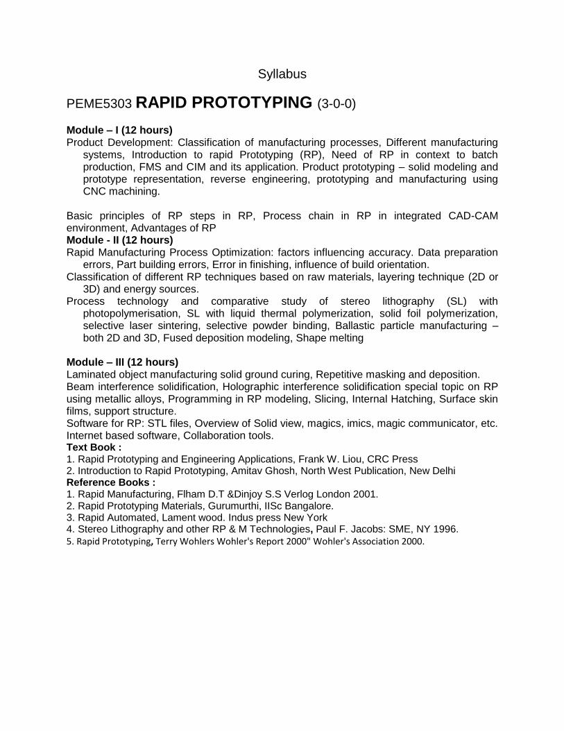
Technologically: Manufacturing is the application of physical and chemical
processes to alter the geometry, properties and or appearance of a given
starting material to make parts or product as shown in Figure
Definition of manufacturing in terms of technology

Economically: Manufacturing is the transformation of materials into items of greater value by means of one or more process and or assembly operation as shown in Figures.
Definition of manufacturing in terms of economic value
Diagrammatic representation of Manufacturing

Factors Contributing to Production Growth
Activities involved in Manufacturing

Development and Progress of Manufacturing
Classification of the Manufacturing Process:
The manufacturing process used in engineering industries basically
perform one or more of the following functions:
Change the physical properties of the work material
Change the shape and size of the work piece.
Produce desired dimensional accuracy and surface finish.
Based on the nature of work involved these processes may be divided
into following seven categories:
1. Processes for changing physical properties of the materials –
Hardening, Tempering, Annealing, Surface Hardening.
2. Casting Processes – Sand Casting, Permanent mold casting, die
casting, Centrifugal casting
3. Primary metal working processes – Rolling, forging, extrusion,
wire drawing
4. Shearing and Forming processes – Punching, blanking, drawing,
bending, forming
5. Joining processes – Welding, brazing, soldering, joining
6. Machining Processes – Turning, drilling, milling, grinding
7. Surface finishing processes – Lapping, honing, superfinishing

Spectrum of Manufacturing Process
MANUFACTURING SYSTEM
The term manufacturing system refers to a collection or arrangement of
operations and processes used to make a desired product or component. It
includes the actual equipment for composing the processes and the
arrangement of those processes. In a manufacturing system, if there is a
change or disturbance in the system, the systems would accommodate or
adjust itself and continue to function efficiently. Normally the effect of
disturbance must be counteracted by controllable inputs or the system
itself. Figure below gives the general definition for any manufacturing
system.
General representation of Manufacturing system

TYPES OF MANUFACTURING SYSTEMS
The manufacturing systems differ in structure or physical arrangement.
According to the physical arrangement, there are four kinds of classical
manufacturing systems and two modern manufacturing systems that is
rapidly gaining acceptance in industries.
The classical systems are
1. Job shop
2. Flow shop
3. Project shop
4. Continuous process
The modern manufacturing systems are
1. Linked cell system (Cellular manufacturing system)
2. Flexible manufacturing system (FMS)
Job shops
In a Job shop, varieties of products are manufactured in small lot sizes to a
specific customer order. To perform a wide variety of manufacturing
processes, general purpose production equipment is required. Workers
must have relatively high skill levels to perform a range of different work
arrangements.
The production machines are grouped according to the general type of
manufacturing processes as shown in Figure below. The lathes are in one
department, drill presses in another and so on. Each different part requiring

its own sequence of operations can be routed through the various
departments in the proper order. For this ‘ROUTE SHEETS’ are used. The
layout made for this purpose is called as functional or process layout.
Functional or process layout
Advantages of process layouts
Can handle a variety of processing requirements
Not particularly vulnerable to equipment failures
Equipment used is less costly
Possible to use individual incentive plans Disadvantages of process layouts
In-process inventory costs can be high
Challenging routing and scheduling
Equipment utilization rates are low
Material handling is slow and inefficient
Complexities often reduce span of supervision
Special attention for each product or customer
Accounting and purchasing are more involved Examples: Machine shops, foundries, press working shops, plastic, industries.

Flow shops The flow shops have a “product oriented layout” composed mainly of flow lines. This system can have high production rates. The plant may be designed to produce the particular product or family, using “Special purpose machines” rather than general purpose equipment. The skill level of the laborer tends to be lower than in production job shop. When the volume of production becomes large, it is called “mass production”. The material flow is through a sequence of operations by material handling devices. The time the item spends in each station or location is fixed and equal. The workstations are arranged in line according to the processing sequence needed as shown in Figure below
Product layout
Advantages of product layout
High rate of output
Low unit cost
Labor specialization
Low material handling cost
High utilization of labor and equipment
Established routing and scheduling
Routing accounting and purchasing

Disadvantages of product layout
Creates dull, repetitive jobs
Poorly skilled workers may not maintain equipment or quality of output
Fairly inflexible to changes in volume
Highly susceptible to shutdowns
Needs preventive maintenance
Individual incentive plans are impractical Example: Automated assembly line and Television manufacturing factory. Project shop In this type, a product must remain in a fixed position or location because of its size and weight. The materials, machines and people in fabrication are brought to site. The layout is also called as fixed position layout. Figure below shows the project shop layout. Example: Locomotive manufacturing, large aircraft assembly and shipbuilding
Project shop layout
Advantages of project layout
Minimum capital investment
Continuity of operation

Less total production cost.
Offers greater flexibility
Allows the change in production design.
Permits a plant to elevate the skill of its operators
Disadvantages of project layout
Machines, tools and workers take more time to reach the fixed
position.
Highly skilled workers are required.
Complicated jigs and fixtures (work holding device) may be required.
Continuous process
In this continuous process, the product seems to flow physically. This
system is sometimes called as flow production when referring to the
manufacture of either complex single parts, such as scanning operation, or
assembled products such as TVs. However, this is not a continuous
process, but high volume flow lines. In continuous process, the products
really do flow because they are liquids, gases, or powers. Figure 1.5 shows
the continuous process layout. It is the most efficient but least flexible kind
of manufacturing system. It usually has the leanest and simplest production
system because this manufacturing system is the easiest to control
because it has the least work- in progress(WIP).
Examples: Oil refineries, chemical process plants and food processing
industries
Continuous process layout
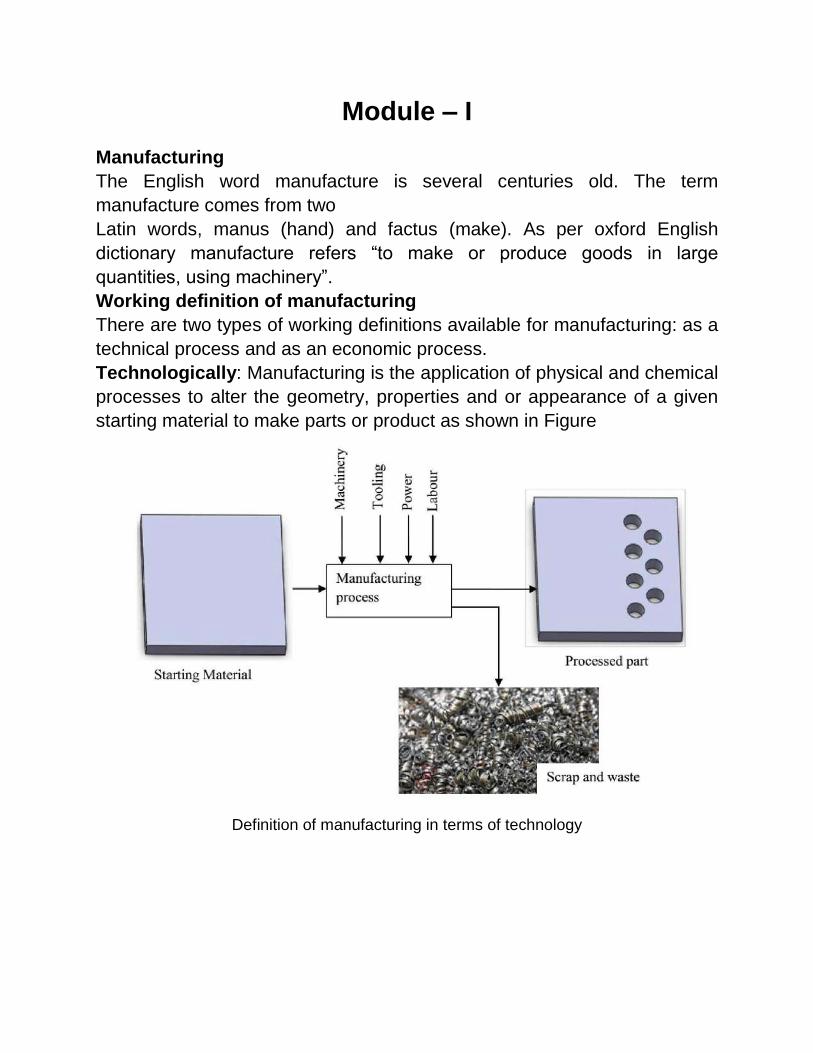
Linked cell manufacturing system
Cellular manufacturing (CM) is a hybrid system for linking the advantages
of both job shops (flexibility in producing a wide variety of products) and
flow lines (efficient flow and high production rate). A cellular manufacturing
system (CMS) is composed of “linked cells”. Figure below shows the main
structure of cellular manufacturing system. In cells, the workstations are
arranged like a flow shop. The machines can be modified, retooled and
regrouped for different product lines within the same “family” of parts. This
system has some degree of automatic control for loading and unloading of
raw materials and work pieces, changing of tools, transferring of work
pieces and tools between workstations. Cells are classified as manned and
unmanned cells. In manned cells multifunctional operators can move from
machine to machine and the materials can be moved by the operator. In
the unmanned cells, an industrial robot is located centrally in the cell for
material handling. Automated inspection and testing equipment can also be
a part of this cell.
Main structure of cellular manufacturing System

Advantages of CMS
The advantages derived from CMS in comparison with traditional
manufacturing systems in terms of system performance have been
discussed in Farrington (1998), Kannan (1999), Suresh (2000),Hug (2001)
and Assad (2003). These benefits have been established through
simulation studies, analytical studies, surveys, and actual implementations.
They can be summarized as follows:
Setup time is reduced: A manufacturing cell is designed to handle parts
having similar shapes and relatively similar sizes. For this reason, many of
the parts can employ the same or similar holding devices (fixtures). Generic
fixtures for a part family can be developed so that time required for
changing fixtures and tools is decreased.
Lot sizes are reduced: Once setup times are greatly reduced in CM, small
lots are possible and economical. Small lots also provide smooth
production flow.
Work-in-process (WIP) and finished goods inventories are reduced:
With smaller lot sizes and reduced setup times, the amount of WIP can be
reduced. The WIP can be reduced by 50%when the setup time is cut to
half. In addition to the reduced setup times and WIP inventory, finished
goods inventory is reduced. Instead of make-to-stock systems with parts
either being run at long, fixed intervals or random intervals, the parts can
be produced either JIT in small lots or at fixed, short intervals.
Material handling costs and time are reduced:
In CM, each part is processed completely within a single cell (wherever
possible). Thus, part travel time and distance between cells is minimal.
A reduction in flow time is obtained:
Reduced materials handling time and reduced setup time greatly reduce
flow time.

Tool requirements are reduced:
Parts produced in a cell are of similar shape, size, and composition. Thus,
they often have similar tooling requirements.
A reduction in space required:
Reductions in WIP, finished goods inventories, and lot sizes lead to less
space required.
Throughput times are reduced:
In a job shop, parts are transferred between machines in batches.
However, in CM each part is transferred immediately to the next machine
after it has been processed. Thus, the waiting time is reduced substantially.
Product quality is improved:
Since parts travel from one station to another as single unit, they are
completely processed in a small area. The feedback is immediate and the
process can be stopped when things go wrong.
Better overall control of operations:
In a job shop, parts may have to travel through the entire shop. Scheduling
and material control are complicated. In CM, the manufacturing facility is
broken down into manufacturing cells and each part travels with a single
cell, resulting in easier scheduling and control.
Flexible manufacturing system
A FMS integrates all major elements of manufacturing into a highly
automated system. The flexibility of FMS is such that it can handle a variety
of part configurations and produce them in any order. Figure 1.7 shows
flexible manufacturing system. The basic elements of FMS are a) works
station b) automated material handling and automated storage and retrieval
systems c) control systems. Because of major capital investment; efficient
machine utilization is essential. Consequently, proper scheduling and
process planning are crucial, that are complex in nature. Because of the
flexibility in FMS, no setup time is wasted in switching between
manufacturing operations; the system is capable of different operations in
different orders and on different machines.

Flexible manufacturing system
Advantages:
Parts can be produced randomly in batch sizes, as small as one, and
at lower cost.
The lead times required for product changes are shorter
Reduced WIP
Labour and inventories are reduced
Production is more reliable, because the system is self-correcting and
so product quality is uniform.
Increased machine utilization
Fewer machines required
Reduced factory floor space
Greater responsiveness to change

Automation: With the advent of mass manufacturing concept, the fruits of technology have reached the common man. Without mass production, cost of the products would have kept several items, which are now common, far beyond the reach of most people. To increase the productivity hence lower the production cost as much as possible automation was introduced in the engineering manufacturing industries. At the onset such automation was primarily named as Automatic Mechanization. These specially designed manufacturing units could be cost effective only when huge quantity of a particular item was needed to be manufactured. The variations in products were few and the demand for individual items was large. Thus this type of automation now- a-days called ‘Hard Automation’. In the 1940’s the concept of computer emerged and that led to the development of ‘numerical control’ for machine tools. Changing a set-up for switching over from one job to another involved changing a substantial amount of the hardware i. e. cams, fixtures, tooling etc. it was time consuming and was expensive also. Once the concept of computer developed it becomes possible to store and feed information with the help of numbers. Numerical control (NC) implies that the necessary information for producing a particular component in a machine can be provided with the help of numbers. Thus switching over from one job to another involved feeding new data and no major modification of the hardware is necessary. Consequently, such units are very flexible in the sense that switching over from one job to another can be done without major time delay and expense. Use of such flexible machines is termed as ‘Flexible Automation’. With the tremendous development in computer science and micro-electronics, flexible automation has become very inexpensive to achieve. The machines are also now directly controlled by computers and such a control is called ‘Computer Numerical Control (CNC)’ It is easy to visualize that with the help of such flexible automation, the requirement of specialized hardware for automatic production of a particular item is eliminated. Cost effective automatic manufacturing has hence become feasible even for small and medium size batches. Figure below indicates the cost effectiveness of different types of manufacturing automation for different ranges of production.

Cost effectiveness of different types of manufacturing automation
Along with the progress in computers, microelectronics and sensor
technology gradually appeared in the technological world i.e. ‘Industrial
Robotics’. With the development of industrial robots, manufacturing
industry entered another era where it became possible to realize the dream
of true automation. The human work force for tending machines and
inspection stations and more important assembly stations could now be
replaced by industrial robots. Figure below shows the various stages of
mechanization and automation in the engineering manufacturing industry.

Stages of Mechanization in Manufacturing
The use of computers in assisting manufacturing started before CAD
developed as useful tool. In the early days the use of computers in
extending the applications of NC technology, specially to part
programming, was termed as computer aided manufacturing (CAM) and it
was delinked from the design activities. Initially CAD and CAM evolved as
separate activities, but gradually it became evident that certain tasks were
common to both. Use of CAD/CAM in an effective manner helps to improve
the design as manufacturing considerations can be incorporated into the
design. A substantial amount of improvement in productivity and quality has

been found to be possible through the use of CAD.CAM technology.
Figure below shows the scheme for CAD/CAM in a modern industry.
Basic scheme of a manufacturing industry using CAD/CAM
Though the application of computers in manufacturing became quite
extensive, the various associated activities still remained
compartmentalized and distinct. Once the technology of flexible automation
matured integration of the different activities became feasible.
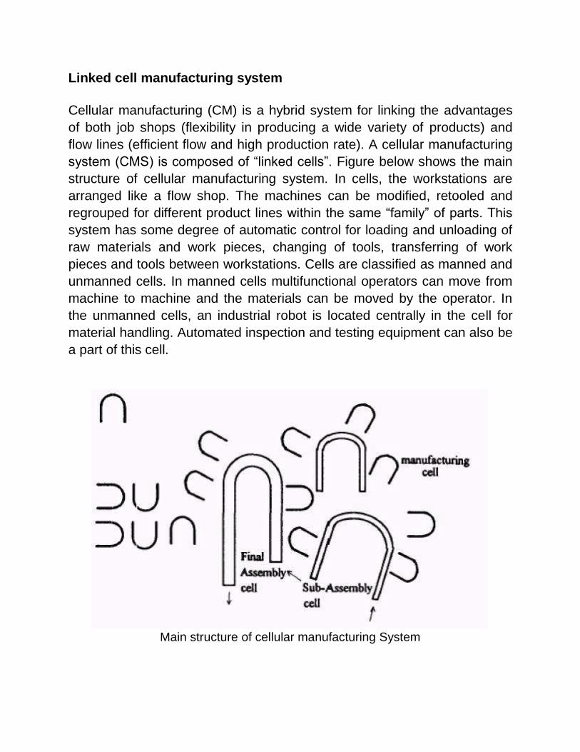
Computer Integrated Manufacturing (CIM)
In a very competitive and open global market survival is possible only if a
good product variety is offered, quality and reliability are assured, cost is
made attractive and the time gap between the conceptualization of a
product and delivery is reduced. To satisfy so many requirements it is
essential to strive for optimal use of man. Machine and material. This is
possible only if all the activities associated with design and manufacturing
are integrated. As mentioned earlier the required electromechanical and
computer technologies for such an integration was ready in 80’s. such a
system is termed as ‘computer integrated manufacturing system’(CIMS)
and the technology has been given the name ‘computer integrated
manufacturing (CIM)’. CIM not only implies the use of computer in
designing a product, planning inventory and production, controlling the
operations and accomplishing many other designs, manufacturing,
management and business related issues but suggest a marriage of the
diverse functions under the control of one central supervisory computer.
The figure below indicates the information flow, material flow and functions
involved in CIM.
Structure of CIM

In concurrent engineering (CE) product is developed by a team involving
engineers from both the design section and the production shop. The
advantages of concurrent engineering are based on the economic leverage
of addressing all aspects of design of a product as early as possible. Hence
using concurrent engineering most of the design modification is
incorporated as early as possible. It is also true that the importance of early
modification is very significant and the ability of the early change to
influence the product cost is much larger as indicated. Hence using
concurrent engineering most of the design modifications are incorporated
as early as possible.
The duration of prototype development is an important factor and it is found
that more than 25% of the total product development time goes in
fabricating the prototype. The figure below shows the typical duration of
product development and prototype fabrication.
(a) Typical duration of product development, (b) typical duration of
prototype development

Figure below indicates the product development cycle and the prototype for
different stages.
Types of prototypes at different stages of product development
In the early stage of product development a ‘design model’ and a
‘geometric prototype’ are prepared. The design model is made
primarily to decide the overall appearance and it is used for
ergonomics analysis. Since there is no functional requirement these
models are easy to process, non metallic materials can be used for
making these models.
In geometric prototypes the dimensional features of the product,
accuracy and tolerances are of primary importance. These prototypes
are also made of model making materials as functional aspects are of
secondary importance. These prototypes are used primarily for
process planning. Appearance and many geometric features are not
considered at this stage.

In the next step technical prototypes are made using the same
material and the same manufacturing processes as the intended final
product. The technical prototypes are useful in assessing various
product qualities like reliability, product life etc.
After the necessary modifications the first series of the product is
manufactured and marketed.
Rapid Prototyping (RP)
Though the principle of concurrent engineering (CE) is quite clear and the
advantages of the concept for improved quality and reduced cost are
implicit, it is not possible to incorporate CE effectively in the absence of
some technique for quick development of prototype. To reduce the
development time and adopt concurrent engineering in its true spirit, quick
and inexpensive fabrication of prototype parts is essential and rapid
prototyping technology has made that possible.
A family of unique fabrication processes developed to make engineering
prototypes in minimum lead time based on a CAD model of the item
•The traditional method is machining
−Machining can require significant lead-times –several weeks, depending
on part complexity and difficulty in ordering materials
•RP allows a part to be made in hours or days given that a computer model
of the part has been generated on a CAD system
WYSIWYG-What You See Is What You Get
Why Rapid Prototyping?
•Because product designers would like to have a physical model of a new
part or product design rather than just a computer model or line drawing
−Creating a prototype is an integral step in design
−A virtual prototype (a computer model of the part design on a CAD
system) may not be sufficient for the designer to visualize the part
adequately
−Using RP to make the prototype, the designer can visually examine and
physically feel the part and assess its merits and shortcomings

Reverse Engineering: In today’s intensely competitive global market, product enterprises are
constantly seeking new ways to shorten lead times for new product
developments that meet all customer expectations. In general, product
enterprise has invested in CADCAM, rapid prototyping, and a range of new
technologies that provide business benefits. Reverse engineering (RE) is
now considered one of the technologies that provide business benefits in
shortening the product development cycle. Figure below depicts how RE
allows the possibilities of closing the loop between what is “as designed”
and what is “actually manufactured”.
Product development cycle
What Is Reverse Engineering?
Engineering is the process of designing, manufacturing, assembling, and
maintaining products and systems. There are two types of engineering,
forward engineering and reverse engineering. Forward engineering is the
traditional process of moving from high-level abstractions and logical
designs to the physical implementation of a system. In some situations,
there may be a physical part/product without any technical details, such as
drawings, bills-of-material, or without engineering data. The process of
duplicating an existing part, subassembly, or product, without drawings,

documentation, or a computer model is known as reverse engineering.
Reverse engineering is also defined as the process of obtaining a
geometric CAD model from 3-D points acquired by scanning/digitizing
existing parts/products. The process of digitally capturing the physical
entities of a component, referred to as reverse engineering (RE), is often
defined by researchers with respect to their specific task.
Reverse engineering is now widely used in numerous applications, such as
Manufacturing, industrial design, and jewelry design and reproduction For
example, when a new car is launched on the market, competing
manufacturers may buy one and disassemble it to learn how it was built
and how it works. In software engineering, good source code is often a
variation of other good source code. In some situations, such as
automotive styling, designers give shape to their ideas by using clay,
plaster, wood, or foam rubber, but a CAD model is needed to manufacture
the part. As products become more organic in shape, designing in CAD
becomes more challenging and there is no guarantee that the CAD
representation will replicate the sculpted model exactly.
Reverse engineering provides a solution to this problem because the
physical model is the source of information for the CAD model. This is also
referred to as the physical-to-digital process depicted in Figure 1.2. Another
reason for reverse engineering is to compress product development cycle
times. In the intensely competitive global market, manufacturers are
constantly seeking new ways to shorten lead times to market a new
product.
Rapid product development (RPD) refers to recently developed
technologies and techniques that assist manufacturers and designers in
meeting the demands of shortened product development time. For
example, injection-molding companies need to shorten tool and die
development time drastically. By using reverse engineering, a three-
dimensional physical product or clay mock-up can be quickly captured in
the digital form, remodeled, and exported for rapid prototyping/tooling or
rapid manufacturing using multi-axis CNC machining techniques.

Why Use Reverse Engineering?
Following are some of the reasons for using reverse engineering:
• The original manufacturer no longer exists, but a customer needs the
product,
e.g., aircraft spares required typically after an aircraft has been in service
for several years.
• The original manufacturer of a product no longer produces the product,
e.g., the original product has become obsolete.
• The original product design documentation has been lost or never existed.
• Creating data to refurbish or manufacture a part for which there are no
CAD data, or for which the data have become obsolete or lost.
• Inspection and/or Quality Control–Comparing a fabricated part to its CAD
description or to a standard item.
• Some bad features of a product need to be eliminated e.g., excessive
wear might indicate where a product should be improved.
• Strengthening the good features of a product based on long-term usage.
• Analyzing the good and bad features of competitors’ products.
• Exploring new avenues to improve product performance and features.
• Creating 3-D data from a model or sculpture for animation in games and
movies.
• Creating 3-D data from an individual, model or sculpture to create, scale,
or reproduce artwork.
• Architectural and construction documentation and measurement.
• Fitting clothing or footwear to individuals and determining the
anthropometry of a population.

Module - II Basic principles of RP
In this process a solid object with prescribed shape, dimension and
finish can be directly produced from the CAD based geometric model
data stored in a computer without human intervention.
Conventional method for producing parts like casting, forming,
machining etc are not suitable for this purpose and a host of new
processes for shaping objects directly from the CAD data have been
developed and machines are in the market.
Rapid prototyping can be of two types:
The parts obtained by RP technology can form the prototype directly
without requiring any further processing.
The parts obtained by RP technology can be used to make moulds
for casting the prototype component. This type is needed because till
today, the commercially available RP machines are non metallic
materials with low strength and low melting temperature.
In general this technology is called as Generative manufacturing Process
(GMP) as the shape of the work piece is not obtained by removal of chips
or forming or casting. It is achieved by addition of material without any prior
recognizable form or shape and no tool is necessary.
In all types of GMPs the CAD model is split into layers as indicated figure
below.
Basic principle of the GMP

The slice thickness and slicing direction can be varied for convenience of generation.
To generate an object of same shape as that of sliced CAD model, the distance between the slicing planes (t) must be equal to the thickness of the corresponding layers during the actual generation process.
The general procedure for obtaining a solid component from a CAD file in shown below:
Steps involved in rapid prototyping

Process chain in RP in integrated CAD-CAM environment
In all commercially developed and technically demonstrated GMP till date the development of part is done by the slicing technique.
However a direct 3-dimensional building up technique is also under active consideration. In this technique it will not be necessary to define the part in terms of thin layers and the process will not require the generation of lower part before the upper part is generated.
Thus, the freedom and flexibility in shape creation and enhanced, but it puts a great burden on programming the generating equipment.
The figure below shows the whole process chain of rapid product development using RP technique.
Process chain for rapid prototype development
Advantages and disadvantages of rapid prototyping
Subtractive type RP is typically limited to simple geometries due to the
tooling process where material is removed. This type of RP also usually
takes a longer time but the main advantage is that the end product is
fabricated in the desired material. Additive type RP, on the other hand, can
fabricate most complex geometries in a shorter time and lower cost.
However, additive type RP typically includes extra post fabrication process
of cleaning, post curing or finishing.
Here is some of the general advantages and disadvantages of rapid
prototyping :
Advantages:
Fast and inexpensive method of prototyping design ideas
Multiple design iterations
Physical validation of design
Reduced product development time
Disadvantages:
Resolution not as fine as traditional machining (millimeter to sub-
millimeter resolution)
Surface flatness is rough (dependant of material and type of RP)

Rapid Manufacturing Process Optimization: factors influencing accuracy
Rapid Manufacturing Process Optimization: factors influencing accuracy. Data preparation
errors, Part building errors, Error in finishing, influence of build orientation.

Module - III
Classification of different RP techniques: A large number of techniques and machines have already been developed in the area or RP and therefore classification/grouping of these processes will be used in presenting descriptions in a structured format. Classification of these processes can be done from two prospective (i) the way material is created/solidified and (ii) the way the shape is generated. A number of processes are still in the R&D stage and some are only in the conceptual stage.
Classification of RP based on layering technique (2D or 3D)

Classification of RP based on state of raw material and energy sources

Steps in RPT
Creation of the CAD model of the (part) design,
Conversion of the CAD model into Standard Tessellation Language (STL) format,
Slicing of the STL file into thin sections,
Building part layer by layer,
Post processing/finishing/joining.
Pre-processing of CAD data
Stereolithography (STL/SLA) with photopolymerozation
RP process for fabricating a solid plastic part out of a photosensitive
liquid polymer using a directed laser beam to solidify the polymer
Part fabrication is accomplished as a series of layers, in which one
layer is added onto the previous layer to gradually build the desired 3-
D geometry
The first addition RP technology -introduced 1988 by 3D Systems Inc.
based on the work of Charles Hull
More installations of STL than any other RP method
Some Facts about STL
Each layer is 0.076 mm to 0.50 mm (0.003 in to 0.020 in.) thick
−Thinner layers provide better resolution and more intricate
shapes; but processing time is longer
The starting materials are liquid monomers
Polymerization occurs upon exposure to UV light produced by
helium-cadmium or argon ion lasers
−Laser scan speeds typically 500 to 2500 mm/s

Stereolithography: (1) at the start of the process, in which the initial layer is added to the platform; and (2) after several layers have been added so that the part geometry gradually takes form
A part produced by Stereolithography
Once the first layer is cured the platform is lowered by distance equal to the thickness of a layer. Then the laser beam scans the next cross section. The cycle is repeated till the topmost layer of the object is generated. Subsequently the generated object is removed from the vat and ultrasonic cleaning removes excess material from crevices and openings. An alcohol bath is used to clean any unused polymer. The process of post curing is carried out by applying intense long wave UV radiation to solidify an uncured liquid trapped in the honeycomb like structures.

In most stereolithography machines solidification occurs in a point-by-point fashion. In some cases solidification takes place curing lines at time. A laser beam scans the liquid surface so that a series of voxels (volume picture cells) get solidified as shown figure below. The voxel size should be adequate to ensure connection with the neighboring voxels and also with the layer solidified prior to the current one.
Generation of lines and layers by voxels
The parameter which controls the voxel overlap is the distance between voxels, the laser power, the stay time and the layer thickness. Using high power lasers, continuous lines can be cured forming a solid parabolic cylinder as hown in figure below.
A parabolic prism cured by a laser beam

Solidification due to curing is achieved once the liquid receives the required dose of radiation. The depth of curing will depend on the exposure and the properties of liquid used.
𝑑𝑐 = 𝑑𝑝𝑙𝑛 (𝐸𝑜𝐸𝑐)
Where: 𝑑𝑐 the depth of a single cured line 𝑑𝑝 the penetration depth of the resin
𝐸𝑜 the centerline exposure on the surface 𝐸𝑐 the critical exposure to which the resin remains liquid Stereolithography with liquid thermal polymerization:
This process solidifies the desired object layer by layer using a liquid polymer as in the case of streolithography.
The primary difference lies in the process of solidification. Unlike the stereolithography process a thermosetting liquid polymer is used in place of photo polymer and the solidification process depends upon heat not light.
In this process a 5W Ar-Ion laser is used.
Post curing is done in an oven at 4000C and the speed of operation is not much different from that incase of SL.
In a system based on liquid thermal polymerization, that dissipation of heat has to be considered carefully for proper control of the voxel size and accuracy.
Thermal shrinkage and distortion can also cause problems in quality control.
However experts think that this problem is not any more severe than that posed by polymerization shrinkage present in other SL operations.
The shrinkage is of the order of 5-6%in volume i.e about 1.6 to 1.8% in linear dimension.
Sterelithography with Solid Foil Polymerization:
In this process solid to solid polymerization is employed rather than
liquid to solid polymerization as in most SL systems.
The raw material consists of semi polymerized plastic foils instead of
liquid resins.
Layer upon layer building process involves applying a foil to the newly
created, topmost, layer of the object and then polymerizing the
required area by a scanning light beam.

The illuminated portions polymerize further and stick to the layer
underneath. The illuminated portions also become insoluble due to
polymerization. So the unexposed portion can be removed later by
dissolving them and the part with required shape and size will
emerge.
Though the raw material is in the form of thin foils, the process should
not be confused with the process of laminated object manufacturing.
The actual creation is still done point by point (or Line by line) instead
of cutting along the boundaries of a cross section.
Solid Ground Curing (SGC)
Like stereolithography, SGC works by curing a photosensitive
polymer layer by layer to create a solid model based on CAD
geometric data
Instead of using a scanning laser beam to cure a given layer, the
entire layer is exposed to a UV source through a mask above the
liquid polymer
Hardening takes 2 to 3 s for each layer
A mask is generated by electro-statically charging a glass plate with
negative image of cross section of the required part. In the meantime, a
thin liquid polymer is spread across the surface of the work-plane. The
mask plate with a negative image of the liquid polymer is positioned over
the thin polymer layer and exposed under the ultraviolet laser lamp for few
seconds.
All parts of the exposed photopolymer layer get solidified with one
exposure. However, the area shaded by the mask is left in a liquid form and
is wiped off with vacuum suction head and replaced by hot wax which acts
as a support to the solidified polymer layer. A face mill makes the surface
of wax and polymer flat and to desired thickness. All the above steps are
repeated till final model embedded in removable wax is obtained.
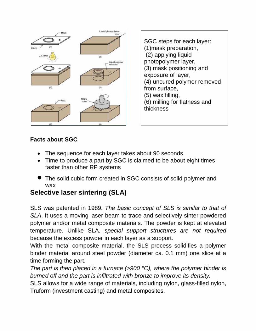
Facts about SGC
The sequence for each layer takes about 90 seconds
Time to produce a part by SGC is claimed to be about eight times faster than other RP systems
The solid cubic form created in SGC consists of solid polymer and wax
Selective laser sintering (SLA) SLS was patented in 1989. The basic concept of SLS is similar to that of
SLA. It uses a moving laser beam to trace and selectively sinter powdered
polymer and/or metal composite materials. The powder is kept at elevated
temperature. Unlike SLA, special support structures are not required
because the excess powder in each layer as a support.
With the metal composite material, the SLS process solidifies a polymer
binder material around steel powder (diameter ca. 0.1 mm) one slice at a
time forming the part.
The part is then placed in a furnace (>900 °C), where the polymer binder is
burned off and the part is infiltrated with bronze to improve its density.
SLS allows for a wide range of materials, including nylon, glass-filled nylon,
Truform (investment casting) and metal composites.
SGC steps for each layer: (1)mask preparation, (2) applying liquid photopolymer layer, (3) mask positioning and exposure of layer, (4) uncured polymer removed from surface, (5) wax filling, (6) milling for flatness and thickness

The parts produced by sintering of powder are porous. Those produced by
sintering polyvinyle chloride have a relative density of only 60% (i.e. 40% of
the part volume in air). New models of SLA machines are being developed
Abbreviation: SLS
Material type: Powder(Polymer) Materials: Thermoplastics: Nylon, Polyamide and Polystyrene;
Elastomers ; Composites Min layer thickness: 0,10mm
Surface finish: Average Build speed: Fast
Applications: Form/ fit testing, Functional testing, Less detailed parts, Parts with snap-fits & living hinges, High heat applications..

in which ceramic and metal powders can be used. One distinct advantage
of SLS is that different materials can be used while building a single part.
For cases where higher energy may be required a high energy electron
beam is proposed to be used for sintering/melting.
Almost all RP techniques produces a vertical ‘stair step’ surface finish as shown in figure below, since parts are built by creating discrete layers. The surface of parts produced by SLS process suffer additionally from roughness problems.
Vertical and Horizontal stair-step effect
One reason is the nature of the raw material, which is powder. Since
sintering does not cause complete melting of the grains (where
diameter lies in the range 80micon to 120 micron) the surfaces
acquire a granular structure.
Besides this raster0scan laser drawing also results in horizontal stair-
step effect as shown in figure above.
However to distribute the roughness evenly on all surfaces the
orientation of raster is rotated by 900 on alternate layers.
Further improvement of surface finish is possible by outlining each
cross section prior to the drawing of rasters. But the last technique
results in higher part building time.

Selective powder binding (SBP)
Shown in figure below
This process is also called three dimensional printing; being developed by MIT is based on creating a solid object from a refractory powder by selecting binding through the application of a colloidal liquid silica binder.
Various stages and steps of selective powder binding (SPB)
In this process a fine jet of ceramic binder in ejected onto the powder layer where solidification is desired. This is done on the inkjet mechanism scans the layer by either ejecting the binder droplets at the identified locations or by deflecting the continuously emerging drops away from the locations where solidification is not wanted. These are termed as ‘ drop-on-demand’ and ‘ continuous jet’ systems respectively.
The droplets are electrically charged at the nozzle and then deflected by applying suitable voltages to electrodes located below the nozzle.

The nozzle is moved across the powder surface in a raster scan while computer generated electrical signals control the deposit of the binder.
Figure below shows an ink-jet mechanism schematically. A vacuum is applied to the
reservoir such that a negative head pressure is maintained at the face plate.
Capillary force at the face plate orifice prevents the binding liquid from being pulled
in through the mechanism. The mechanical impulse created on applying electrical
charge to the piezoelectric crystal produces a shock wave which causes the ejection
of a droplet from the face plate.
Schematic view of an ink-jet mechanism
The print head consists of an array of a large number of jet ports each one capable of
operating at 10KHz. With an array of high frequency jets, the layer solidification time
can be 4s/layer for a drop on demand system with a layer size of 0.5mx0.5m. it can be
as low as a fraction of a second for ‘continuous jet’ system.
The major problem with the parts produced by this technique is inadequate surface
finish. Removal of unbound powder from narrow passages and enclosed cavities also
poses difficulties. This process is however, very convenient for making moulds with
integral cores. Since the fabrication of the mould and the core is done as a single unit,
the registration of cores to the mould is precise.
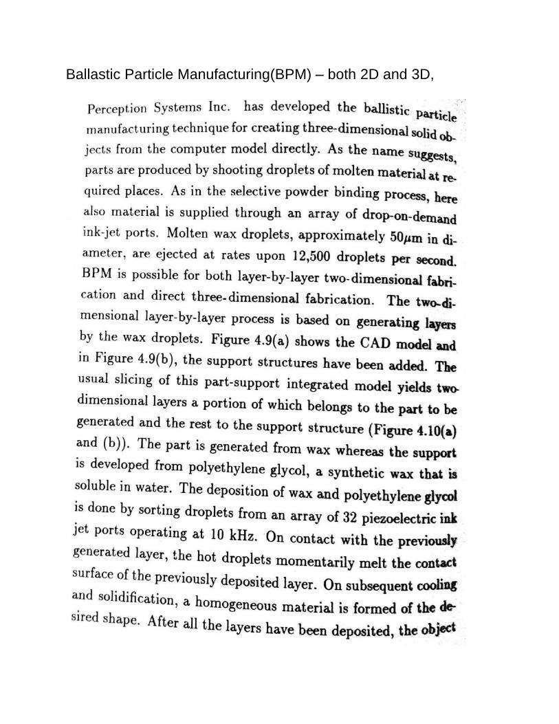
Ballastic Particle Manufacturing(BPM) – both 2D and 3D,


Fused deposition modeling,


head pauses. It is being proposed to develop a system which will provide a quick downward movement when the head is still in motion. This may eliminate the above mentioned problem. It is important that the head be kept in motion at all times. Otherwise material melts near the tip and forms little bumps which may be visible on the surface layers. Temperature control of the FDM head and the part is crucial for the success. There is no wastage of material in this process and parts produced by FDM do not require a major cleaning operation after fabrication.
Shape melting
The process is very similar to fused deposition modeling and was
developed by Babcock and Wilcox. The basic idea behind this process is to
build parts directly from welding material melted by sticking an arc as in arc
welding. This is similar to the technique often used in the industry to repair
worn components, broken gear teeth etc. A band or thread of metal is
melted and deposited by arc welding and the desired shape is obtained by
controlling the position of the welder with the help of a robot. A controlled
cooling system is used to ensure fast solidification. With the currently
available system, the major limitations are the accuracy and finish.
Accuracy better than 1mm is presently not possible. Further there are
problems in producing parts of sizes smaller than 7 mm.
The major advantage of this process is that the metal parts produced by
this process can be directly used for making functional prototypes.
Materials used till date includes Iconel (alloy625), tungsten carbide and
other alloy. The advantage also includes high strength isotropic material
properties and the possibility of developing multi material parts with tailored
properties. Moreover, a uniform fine grained micro structure is produced by
this process.

Module – IV Laminated object manufacturing
Laminated object manufacturing process

The entire surface of the sheet material is coated with adhesive, there fore each layer adheres to the previously laid layer at all points of contact. Though the laser beam cut the layers to separate a corss section from the ribbon of the work material it cannot separate the layers once they are glued. These results in a problem where an unwanted part of an upper layer remains glued to the previous cross section. Figure (a) shows a tapered object under fabrication by LOM, Fig (b) shows the lamination pattern to be generated by laser cutting and layer deposition.
Inter layer adhesion problem in LOM

Figure c above shows the actual fabrication process and the undesirable
gluing between the desired and undesired parts of successive layers. Thus
all down facing surfaces of the part tend to adhere to the block and
separation becomes difficult after the generation is over. Currently the
problem is reduced by a method called burn out. The area on the
previously laid layer where gluing is undesirable, is cut with a tightly spaced
cross hatch pattern. However this problem of LOM is a serious hurdle till
now. Attempt is being made to develop techniques to glue the sheet only
within the parts cross section. One way to achieve this is to apply a heat
sensitive glue all over the surface and then scan the cross sectional area
with a laser beam thus heating and thus gluing the sheets only at the
desired area.
Another way to solve this unwanted gluing problem is to use an UV
sensitive glue along with. Selective gluing can be achieved by scanning the
required area with an UV laser. Another technique is that of printing a mask
to the foil and then illuminating with UV lamps through a glass plate
pressing the sheet on the stack. The principle is shown below.
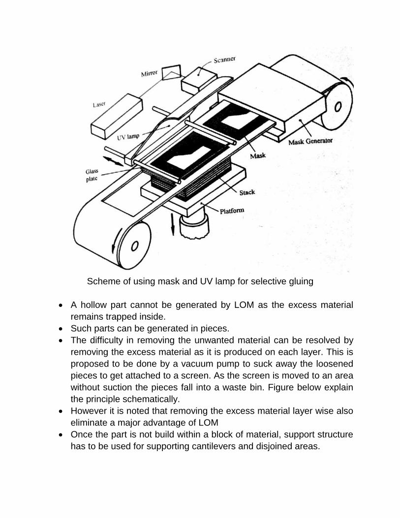
Scheme of using mask and UV lamp for selective gluing
A hollow part cannot be generated by LOM as the excess material
remains trapped inside.
Such parts can be generated in pieces.
The difficulty in removing the unwanted material can be resolved by
removing the excess material as it is produced on each layer. This is
proposed to be done by a vacuum pump to suck away the loosened
pieces to get attached to a screen. As the screen is moved to an area
without suction the pieces fall into a waste bin. Figure below explain
the principle schematically.
However it is noted that removing the excess material layer wise also
eliminate a major advantage of LOM
Once the part is not build within a block of material, support structure
has to be used for supporting cantilevers and disjoined areas.
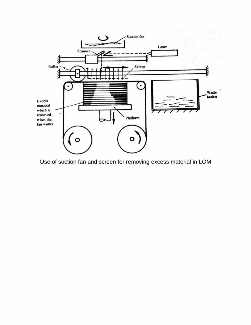
Use of suction fan and screen for removing excess material in LOM

Repetitive masking and deposition
Scheme of MD process
.

Electric arc spray gun

Principle of Beam Interference solidification


Holographic interference solidification The exotic process process is also based on photo polymerization of photo
sensitive resins. But in this process the part creation is not done voxel by
voxel instead a three dimensional holographic image is projected in a vat
containing a photo sensitive liquid monomer and a whole three dimensional
surface gets solidified at once. The holographic film for projecting the
image is created with a CAD system. A system based on this principle has
been developed.

Special topic on RP using metallic alloys DIRECT METAL LASER SINTERING (DMLS)
DMLS technology was developed jointly by Rapid Prototyping Innnovations
(RPI) and EOS Gmbh in 1994. It was the first commercial RP-method to
produce metal parts in a single process. Metal powder (20 μm diameter)
without binder is completely melted by scanning of a high power laser
beam. The density of a produced part is about 98 %. SLS has about 70 %.
One advantage of DMLS compared to SLS is the small size of particles
which enables very detailed parts.
Abbreviation: DMLS Materialtype: Powder(Metal)
Materials: Ferrousmetalssuchas Steel alloys, Stainlesssteel, Toolsteel; Aluminium, Bronze,Cobalt-chrome, Titanium, Ceramics..
Min layerthickness: 0,02mm
Surfacefinish: Average
Buildspeed: Fast Applications: Form/fittesting,Functionaltesting, Rapidtooling,
Highheatapplications, Medicalimplants, Aerospaceparts..

, Slicing


Various types of supports
