led driver constant voltage driver lc 60w 24v sc snc
TRANSCRIPT
www.tridonic.com 1Subject to change without notice. Information provided without guarantee.
Data sheet 01/22-LC475-17
LED driver
Constant voltage
Product description
• Constant voltage LED driver
• Output voltage 24 V
• Max. output power 60 W
• Dimmable via external PWM LED dimmers attached on output
side
• Nominal lifetime up to 50,000 h
• 5 years guarantee (conditions at www.tridonic.com)
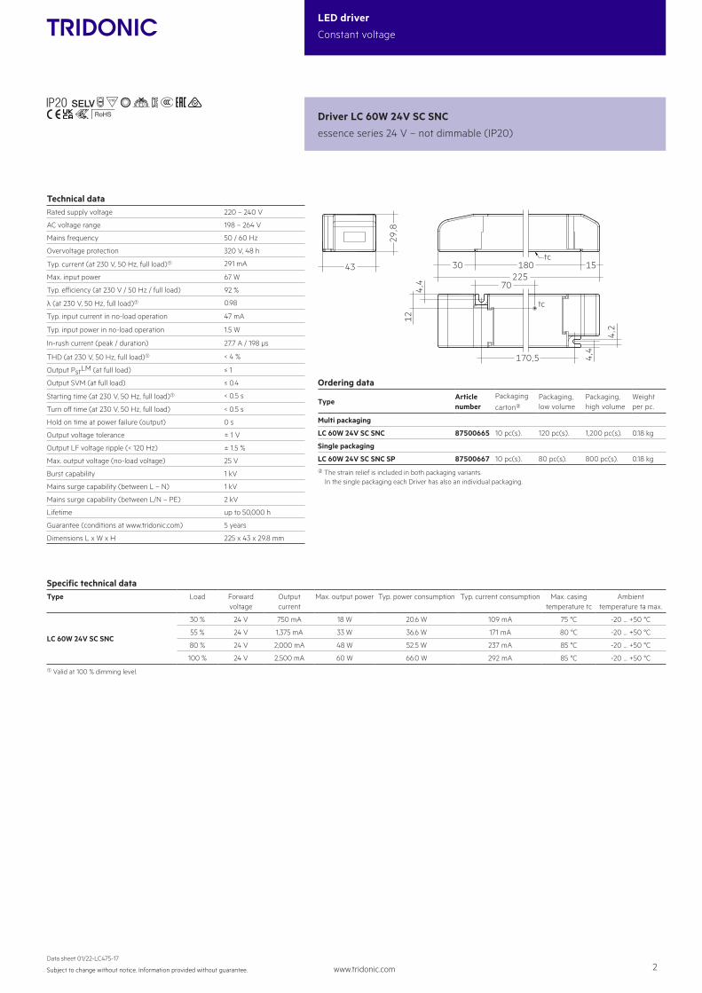
Typical application
• Cove lighting, facade accent lighting, ceiling integration,
refrigerated displays
Technical details
• 24 V, 60 W
• Small design (225 x 43 x 30 mm) with stretched-compact
strain relief
• Very good THD performance in wide load range < 5 %
• Output LF voltage ripple (< 120 Hz) 1.5 %
• Small cross section
• Push terminal for simple wiring
System solution
• Tridonic LLE-FLEX ADV G2 600, 1,200, 1,800 lm/m
• Tridonic LLE-FLEX EXC 600, 1,200, 1,800, 2,500 lm/m
• In connection with Flex accessories wire to PCB plug•
ÈStandards, page 3
Driver LC 60W 24V SC SNC
essence series 24 V – not dimmable (IP20)
www.tridonic.com 2Subject to change without notice. Information provided without guarantee.
Data sheet 01/22-LC475-17
LED driver
Constant voltage
Technical dataRated supply voltage 220 – 240 V
AC voltage range 198 – 264 V
Mains frequency 50 / 60 Hz
Overvoltage protection 320 V, 48 h
Typ. current (at 230 V, 50 Hz, full load)1 291 mA
Max. input power 67 W
Typ. efficiency (at 230 V / 50 Hz / full load) 92 %
λ (at 230 V, 50 Hz, full load)1 0.98
Typ. input current in no-load operation 47 mA
Typ. input power in no-load operation 1.5 W
In-rush current (peak / duration) 27.7 A / 198 μs
THD (at 230 V, 50 Hz, full load)1 < 4 %
Output PstLM (at full load) ≤ 1
Output SVM (at full load) ≤ 0.4
Starting time (at 230 V, 50 Hz, full load)1 < 0.5 s
Turn off time (at 230 V, 50 Hz, full load) < 0.5 s
Hold on time at power failure (output) 0 s
Output voltage tolerance ± 1 V
Output LF voltage ripple (< 120 Hz) ± 1.5 %
Max. output voltage (no-load voltage) 25 V
Burst capability 1 kV
Mains surge capability (between L – N) 1 kV
Mains surge capability (between L/N – PE) 2 kV
Lifetime up to 50,000 h
Guarantee (conditions at www.tridonic.com) 5 years
Dimensions L x W x H 225 x 43 x 29.8 mm
Driver LC 60W 24V SC SNC
essence series 24 V – not dimmable (IP20)
22570
30 180 15
4,2
4,4
4,4
170,5
29,8
43
tc
12
tc
Ordering data
TypeArticle number
Packaging
carton2Packaging, low volume
Packaging, high volume
Weight per pc.
Multi packaging
LC 60W 24V SC SNC 87500665 10 pc(s). 120 pc(s). 1,200 pc(s). 0.18 kg
Single packaging
LC 60W 24V SC SNC SP 87500667 10 pc(s). 80 pc(s). 800 pc(s). 0.18 kg
2 The strain relief is included in both packaging variants. In the single packaging each Driver has also an individual packaging.
Specific technical dataType Load Forward
voltageOutput current
Max. output power Typ. power consumption Typ. current consumption Max. casing temperature tc
Ambient temperature ta max.
LC 60W 24V SC SNC
30 % 24 V 750 mA 18 W 20.6 W 109 mA 75 °C -20 ... +50 °C
55 % 24 V 1,375 mA 33 W 36.6 W 171 mA 80 °C -20 ... +50 °C
80 % 24 V 2,000 mA 48 W 52.5 W 237 mA 85 °C -20 ... +50 °C
100 % 24 V 2,500 mA 60 W 66.0 W 292 mA 85 °C -20 ... +50 °C
1 Valid at 100 % dimming level.

www.tridonic.com 3Subject to change without notice. Information provided without guarantee.
Data sheet 01/22-LC475-17
LED driver
Constant voltage
1. Standards
EN 55015EN 61000-3-2EN 61000-3-3EN 61347-1 EN 61347-2-13 EN 62384EN 61547IEC 60335-1IEC 60335-2-89
3. Installation / wiring
2. Thermal details and lifetime
3.1 Circuit diagram
2.1 Expected lifetime
The LED control gear is designed for a lifetime stated above under reference conditions and with a failure probability of less than 10 %.The relation of tc to ta temperature depends also on the luminaire design. If the measured tc temperature is approx. 5 K below tc max., ta temperature should be checked and eventually critical components (e.g. ELCAP) measured. Detailed information on request.
3.2 Mains supply wiring
The wiring can be in stranded wires with ferrules or solid from 0.5 – 1.5 mm². For perfect function of the push-wire terminals (WAGO 250) the strip length should be 7.2 – 8.8 mm.
1.1 Glow wire test
according to EN 61347-1 with increased temperature of 850 °C passed.
LC 60W 24V SC SNC
PRI
220–240 V
LN
50/60 Hz
~~
SEC
+ LED
– LED
Expected lifetimeType Output load ta 40 °C 45 °C 50 °C
LC 60W 24V SC SNC> 33 ... ≤ 60 W
tc 75 °C 80 °C 85 °C
Lifetime 90,000 h 65,000 h 45,000 h
≤ 33 Wtc 70 °C 75 °C 80 °C
Lifetime >100,000 h >100,000 h 75,000 h
– mm
wire preparation: – mm²
Primary strain relief for cables with bigger cable sheath
Permissible cable jacketdiameter: 2.2 – 9 mm
Permissible cable jacketdiameter: 3 – 9 mm
Secondary strain relief for cable with smaller cable sheath
43
34
www.tridonic.com 4Subject to change without notice. Information provided without guarantee.
Data sheet 01/22-LC475-17
LED driver
Constant voltage
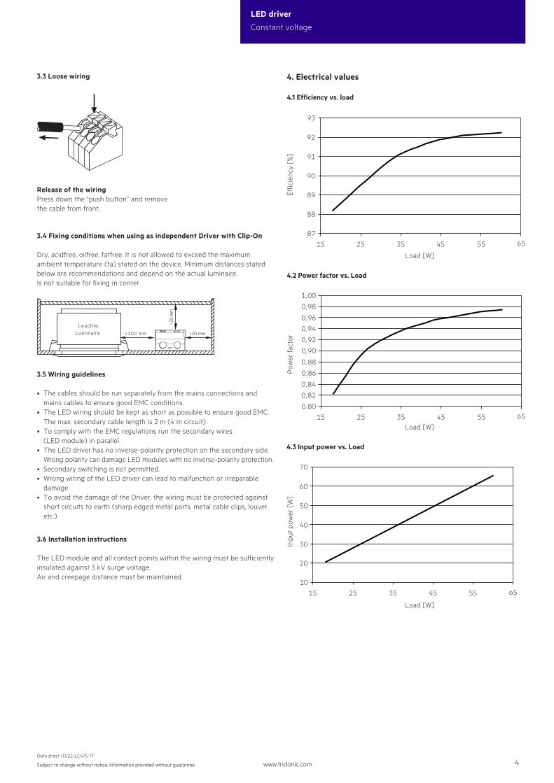
4.1 Efficiency vs. load
4. Electrical values
Load [W]
Load [W]
Load [W]
Effic
ienc
y [%
]P
ower
fact
orIn
put
pow
er [
W]
4.2 Power factor vs. Load
4.3 Input power vs. Load
87
88
90
89
15 35 45 5525 65
93
92
91
0,80
0,82
0,84
0,86
0,88
0,90
0,92
0,96
0,94
0,98
1,00
15 45 5525 35 65
10
20
30
50
60
70
15 5535 4525 65
40
3.3 Loose wiring
Release of the wiringPress down the “push button” and remove the cable from front.
3.5 Wiring guidelines
• The cables should be run separately from the mains connections and mains cables to ensure good EMC conditions.
• The LED wiring should be kept as short as possible to ensure good EMC. The max. secondary cable length is 2 m (4 m circuit).• To comply with the EMC regulations run the secondary wires (LED module) in parallel.• The LED driver has no inverse-polarity protection on the secondary side. Wrong polarity can damage LED modules with no inverse-polarity protection.• Secondary switching is not permitted.• Wrong wiring of the LED driver can lead to malfunction or irreparable damage.• To avoid the damage of the Driver, the wiring must be protected against short circuits to earth (sharp edged metal parts, metal cable clips, louver, etc.).
3.6 Installation instructions
The LED module and all contact points within the wiring must be sufficiently insulated against 3 kV surge voltage.Air and creepage distance must be maintained.
3.4 Fixing conditions when using as independent Driver with Clip-On
Dry, acidfree, oilfree, fatfree. It is not allowed to exceed the maximum ambient temperature (ta) stated on the device. Minimum distances stated below are recommendations and depend on the actual luminaire. Is not suitable for fixing in corner.
>100 mm
LeuchteLuminaire >20 mm
>20
mm
www.tridonic.com 5Subject to change without notice. Information provided without guarantee.
Data sheet 01/22-LC475-17
LED driver
Constant voltage
Automatic circuit breaker type C10 C13 C16 C20 B10 B13 B16 B20 Inrush current
Installation Ø 1.5 mm2 1.5 mm2 2.5 mm2 2.5 mm2 1.5 mm2 1.5 mm2 2.5 mm2 2.5 mm2 Imax
time
LC 60W 24V SC SNC 28 37 47 58 17 22 28 35 27.7 A 198 μs
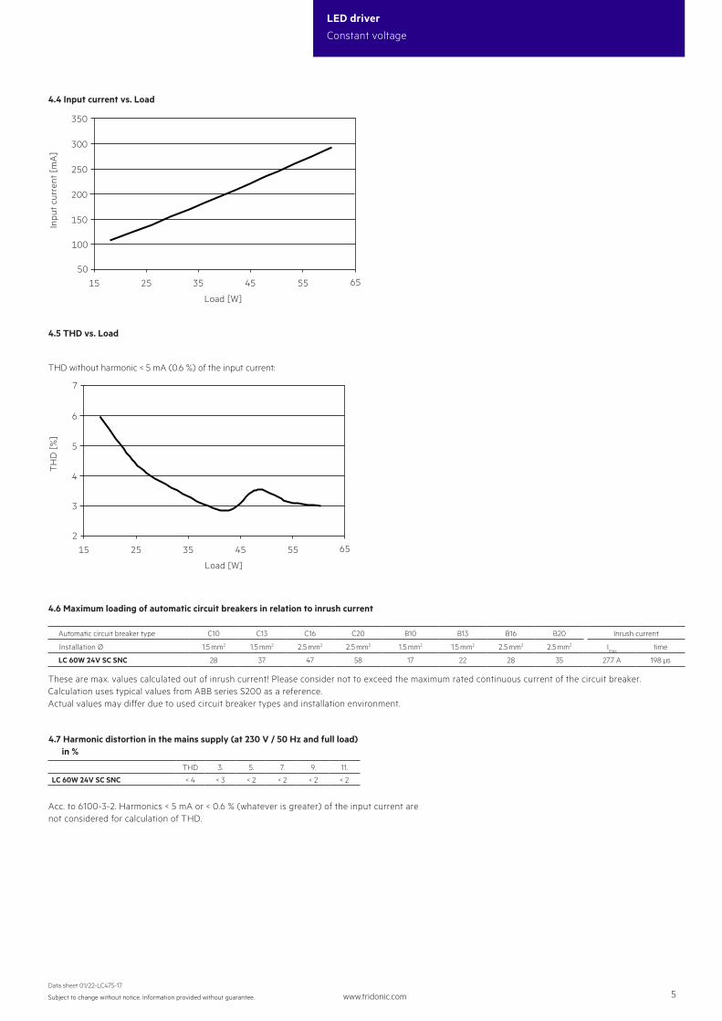
4.7 Harmonic distortion in the mains supply (at 230 V / 50 Hz and full load) in %
THD 3. 5. 7. 9. 11.
LC 60W 24V SC SNC < 4 < 3 < 2 < 2 < 2 < 2
Inpu
t cu
rren
t [m
A]
TH
D [
%]
4.4 Input current vs. Load
4.5 THD vs. Load
50
100
150
200
250
300
350
15 5535 4525 65
2
3
5
6
7
15 553525 45 65
4
Load [W]
Load [W]
Acc. to 6100-3-2. Harmonics < 5 mA or < 0.6 % (whatever is greater) of the input current are not considered for calculation of THD.
THD without harmonic < 5 mA (0.6 %) of the input current:
4.6 Maximum loading of automatic circuit breakers in relation to inrush current
These are max. values calculated out of inrush current! Please consider not to exceed the maximum rated continuous current of the circuit breaker. Calculation uses typical values from ABB series S200 as a reference.Actual values may differ due to used circuit breaker types and installation environment.
www.tridonic.com 6Subject to change without notice. Information provided without guarantee.
Data sheet 01/22-LC475-17
LED driver
Constant voltage
5. Functions
7.2 Conditions of use and storage
Humidity: 5 % up to max. 85 %, not condensed (max. 56 days/year at 85 %)
Storage temperature: -40 °C up to max. +80 °C
The devices have to be acclimatised to the specified temperature range (ta) before they can be operated.
The LED driver is declared as inbuilt LED controlgear, meaning it is intended to be used within a luminaire enclosure.If the product is used outside a luminaire, the installation must provide suitable protection for people and environment (e.g. in illuminated ceilings).
7.1 Insulation and electric strength testing of luminaires
Electronic devices can be damaged by high voltage. This has to be considered during the routine testing of the luminaires in production.
According to IEC 60598-1 Annex Q (informative only!) or ENEC 303-Annex A, each luminaire should be submitted to an insulation test with 500 V DC for 1 second. This test voltage should be connected between the interconnected phase and neutral terminals and the earth terminal. The insulation resistance must be at least 2 MΩ.
As an alternative, IEC 60598-1 Annex Q describes a test of the electrical strength with 1500 V AC (or 1.414 x 1500 V DC). To avoid damage to the electronic devices this test must not be conducted.
7. Miscellaneous
5.3 Short-circuit behaviour
In case of a short circuit at the LED output the LED output is switched off. When fault is removed, the driver can go back to work automatically without resetting input main power.
5.1 Overload protection
If the maximum load is exceeded by a defined internal limit, the LED will flicker, and output voltage will be reduced.When fault is removed, the driver can go back to work automatically without resetting input main power.
5.2 Overtemperature protection
The LED driver is protected against temprorary thermal overheating. If the temperature limit is exceeded the LED will flicker, and restart automatically after the driver cold down. The temperature protection is activated approx. + 15 °C above Tc max.
5.4 No-load operation
The LED driver will not be damaged in the no-load operation. When the output is floating and doesn‘t connect the LED modules, the output voltage will keep the max. voltage (< 25 V). After connecting the LED load, the driver works nor-mally without resetting the main power.
5.5 Hot plug-in
Hot plug-in is supported.If a LED load is connected, the device does not need to be restarted before the output will be activated again.
7.4 Additional information
Additional technical information at www.tridonic.com → Technical Data
Lifetime declarations are informative and represent no warranty claim.No warranty if device was opened.
7.3 Maximum number of switching cycles
All LED driver are tested with 50,000 switching cycles.
5.6 Use of PWM dimmers
PWM dimmers are used to dim the attached LED module.For fulfilling the ecodesign requirements of the European Union following has to be considered:• Going to stand-by via PWM dimmer is not supported. • To turn off the luminaire, mains has to be off.