led packaging for lighting applications (design, manufacturing and testing) || appendix: measurement...
TRANSCRIPT

Appendix
Measurement Method forIntegral LED Road LightsApproved by China Solid StateLighting Alliance
The China Solid State Lighting Alliance (CSA) has recently approved recommendation
Measurement Method for LED Road Lights, which was drafted by a group of experts led
by Professor Jiangen Pan in 2008, and revised in 2009.
1 Scope
This recommendation regulates the measurement method for basic characteristics of Integral
LED Road Lights.
This recommendation applies to integral LED road lights used for roadway lighting, which
operate stably when driven by an internal controller (self-ballasted) or an external controller
and supplied by alternating current with 50Hz/220V.
This recommendation is of reference to those LED road lights which are above the scope of
this recommendation or other similar products.
2 Normative References
The items, cited by this recommendation in the following documents, become its items. This
recommendation does not apply to all modified documents (excluding the corrected contents)
or revised editions, if the citations are dated. However, all the parties involving in reaching
agreement on this recommendation are encouraged to conduct research on whether they can
LED Packaging for Lighting Applications: Design, Manufacturing and Testing, First Edition. Sheng Liu andXiaobing Luo.� 2011 Chemical Industry Press. All rights reserved. Published 2011 by John Wiley & Sons (Asia) Pte Ltd.

make use of the latest editions of these documents. As to the undated citations, the latest
editions are suitable for this recommendation. Relevant documens are as follows:
JJG 211-2005. Luminance meter calibrating regulations;
JJG 245-2005. Illuminance meter calibrating regulations;
GB/T 5702-2003. Evaluation methods of color rendering properties of light sources;
GB/T 7922-2003. Measuring methods of the color of light sources;
GB 17625.1-2003. Electromagnetic compatibility (EMC), limits value, measurement method
of harmonic current emission (equipment input current� 16A) (IEC 61000-3-2, IDT);
GB 17743-1999. Limits and measuring methods of radio disturbance characteristics of
electrical lighting appliance and similar equipment (idt CISPR 15);
GB/T 18595-2001. Requirements of electromagnetic compatibility and immunity of general
lighting equipment (idt IEC 61547);
CIE 15-2004. Colorimetry;
CIE 70-1987. The measurement of absolute luminous intensity distribution;
CIE 84-1989. The measurement of luminous flux;
CIE 102-1993. Recommended file format for electronic transfer of luminaries photometric
data; and
CIE121-1996. Photometry and goniophotometry of luminaries.
3 Definitions
This recommendation adopts the following definitions.
3.1 Integral LED Road Light
The integral LED road light is an integrated light source device which is used for road lighting.
An LED which is used as the light source, is composed of components such as optics,
mechanical, electric, and electronic components. The LED is integrated with the light and it is
a non-removable and irreplaceable part of the light; for clarification, it is called the LED road
light. It is driven by an internal controller (self-ballasted) or an external controller.
3.2 Self-ballasted Integral LED Road Light
It is the integral LED road light which is accompanied by an internal controller and can be
connected to the power supply directly; called a self-ballasted LED road light for short.
3.3 Externally Controlled Integral LED Road Light
It is the integral LED road light which is connected to the power supply through external
controller; called an externally controlled LED road light for short.
3.4 LED Reference Controller
The external controller which provides reference working conditions for an externally
controlled LED road light.
LED Packaging for Lighting Applications 332

3.5 Standard LED Road Light
A stable and reproducible LED road light, which is calibrated with basic photoelectric per-
formance parameters. It can calibrate the measuring equipment with the substitution method.
A standard LED road light should be provided with a temperature monitoring point and the
reference working temperature of this point.
3.6 Initial Values
The photometric, colorimetric, and electric quantities of an LED road light, providing stable
lighting under specified conditions.
3.7 Reference Axis
The reference axis refers to the axis which goes through the center of the luminous surface and
is vertical to the luminous surface.
3.8 Photometry Center
The photometry center refers to the center of the luminous surface of the LED road light. In the
goniophotometric measurement, the photometry center of the tested LED road light should be
at the rotation center of the goniophotometer.
3.9 Measuring Half-plane (C Plane)
Measuring half-plane (C plane) refers to the half-planewhich goes through the reference axis of
the LED road light with the reference axis as its initial rotating line. It is called the measuring
plane, or C plane for short, to avoid confusion. For road lights, the planes parallel to the
longitude axis of the road are defined as C0� and C180� planes, and a C90� plane is defined asthe half plane vertical to the longitude axis at the roadside, and a C270� plane is the half planevertical to the longitude axis at the houseside, as shown in Figure A1.
3.10 Auxiliary Axis
The auxiliary axis goes through the photometry center of the LED road light and is vertical to
the reference axis; in practial applications it is always parallel to the direction of the road. The
auxiliary axis and the reference axis define the C0�/C180� plane.
3.11 Third Axis
The third axis goes through the photometry center and is vertical to reference axis; in practical
applications it is always vertical to the direction of the road. The third axis and reference axis
define the C90�/C270� plane.
3.12 Standard Measurement Attitude
The luminous surface of the LED road light is horizontal and spreads light downward.
333 Appendix: Measurement Method for Integral LED Road Lights

3.13 Right Downward Point
It refers to the point which is just below the LED road light and usually on the reference axis.
3.14 Measurement Distance
It refers to the effective optical distance from the rotating center of the axes to the receiving
surface center of the goniophotometer or the goniospectroradiometer.
3.15 Half-peak Side Angle
Taking the light center as the origin, the angle between the reference axis and the direction in
which the LED road light has a luminous intensity of 50% of the maximum value. (If two or
more directions are of 50% maximum luminous intensity, take the largest angle.)
3.16 Total Luminous Flux
The total amount of luminous flux of all directions generated by the LED road light; it is called
luminous flux to avoid confusion.
Figure A1 Coordinate system of the light distribution of LED road light.
LED Packaging for Lighting Applications 334

3.17 Upward (Downward) Flux Fraction
It refers to the luminous flux of the LED road light in the directions above or below the
horizontal plane of the photometry center.
3.18 Luminous Efficacy
It refers to the quotient of the total luminous flux by the power consumed of an LED road light,
unit: l m/W.
3.19 Flashed Area
It refers to the projected area of the luminous part observed in the direction of C¼ 0� or 180�,g¼ 76�.
3.20 Average Color Nonuniformity
It refers to the color difference between the average color after all light emitted from an LED
road light is mixed, and the color of the light in the direction of the reference axis.
3.21 Maximum Color Nonuniformity
It refers to the maximum color difference between the light emitted from any direction in the
half peak beam angle, and the light from the reference axis direction.
3.22 Lumen Maintenance
It refers to the ratio of the luminous flux at a given time in its life time and the initial luminous
flux when the LED road light is operated under specified conditions, expressed as a percentage
value. For simplicity of measurement, the illuminance at a right downward point can replace
the luminous flux to calculate the lumen maintenance.
3.23 Color Shift
It refers to the difference between the colorimetric quantities at a given time in its life time and
the initial quantities when the LED road light is operated under specified conditions. It can be
represented by the coordinate difference in the CIE 1976 uniform color space of the average
color or the right downward point at a certain distance of the LED road light.
3.24 Allowable Ambient Temperature Range
It refers to the range from the lowest temperature at which LED road light can be lit up
normally, to the highest temperature at which LED can operate normally.
335 Appendix: Measurement Method for Integral LED Road Lights

4 Main Measurement Items
4.1 Basic Electric Characteristics
4.1.1 Voltage
4.1.2 Current
4.1.3 Power
4.1.4 Power Factor
4.1.5 Frequency
4.2 Electromagnetic Compatibility (EMC)
Electromagnetic compatibility of a self-ballasted LED road light mainly includes radio
disturbance characteristics, harmonic performance of input current, and immunity character-
istics. Electromagnetic compatibility of an LED road light with an external controller includes
radio disturbance characteristics and immunity characteristics of the input port.
4.3 Optical Performance
4.3.1 Luminous Flux and Efficacy
4.3.2 Luminous Intensity Distribution Characteristics
4.3.3 Flashed Area and Average Luminance Characteristics
4.3.4 Colorimetric Characteristics
4.3.4.1 Average Chromaticity
4.3.4.2 Average Color Rendering Index
4.3.4.3 Spatial Colorimetric Distribution Characteristics
4.3.4.4 Spatial Color Non-uniformity
(a) Average Color Non-uniformity
(b) Maximum Color Non-uniformity
4.4 Temperature Characteristics and Luminous Maintenance
4.4.1 Luminous Flux versus Temperature Curves
4.4.2 Highest Allowable Ambient Temperature
4.4.3 Endurance of High-Low Temperature Cycling
4.4.4 Luminous Maintenance Characteristics
LED Packaging for Lighting Applications 336

4.4.4.1 Lumen Maintenance
4.4.4.2 Color Shift
4.4.5 On/Off Characteristics
5 General Requirements and Equipment Requirementsfor Measurment
5.1 Working Conditions
Unless otherwise specified, tests or measurements shall be conducted under the working
conditions detailed below.
5.1.1 Laboratory Environmental Conditions
The Electric, photometric, and colorimetric measurement should be conducted with the LED
road light in an environment maintained at an ambient temperature of 25�C� 1�C, relativehumidity of�65% and should be draught-free. There should be no airmovement in the vicinity
of the test LED road light.
For luminous maintenance measurement and on/off test, the ambient temperature shall be in
the range of 25�C� 5�C, relative humidity of �65% and should be draught-free.
The measurement point of ambient temperature should be at the same level of the
photometry center of the LED road light, 0.5meters away from the tested LED road light;
thermo-probe should not be projected by the LED road light.
Air pressure: 86 kPa–106 kPa.
5.1.2 Power Supply Requirements
Self-ballasted controlled LED road lights should be tested or measured at specified voltage
(if the specified voltage has a range, choose the medium value) and frequency. During
stabilization, the voltage should be constant within �0.5%; during the measurement, the
power voltage should be constant within�0.2%, and the fundamental frequency error shall not
exceed 0.1% and the total harmonic content shall not exceed 3% of the fundamental; as for the
aging and life test, it should be constant within �2%.
An externally controlled LED road light shall operate under the drive of a reference control
gear or equivalent driven condition. The output voltage/current/power of the special facility
shall be maintained constant within�0.2%, and the total harmonic content and the frequency
error shall be specified if the facility is AC output, generally, the frequency error shall not
exceed 0.1%, and the harmonic content shall not exceed 3% of the fundamental.
5.1.3 Operation State Requirements of the Measured LED Road Light
The optical characteristics of an LED road light are sometimes restricted by the work attitude
due to heat dissipation issue, so when it is tested or measured with no special requirements,
the LED light should be placed in a free space in the specified standard measurement attitude.
During the sampling in the measurement, LED road lights should be kept static.
LED road lights should operate in a state of thermal equilibrium. The temperature of an LED
road light itself should bemonitored at the same timewhilemonitoring the ambient temperature to
337 Appendix: Measurement Method for Integral LED Road Lights

keep a good reproducibility. If it is possible to monitor the junction voltage of LED lights,
it should be monitored. Otherwise, the temperature of the designated position of the shell
should be monitored.
5.1.4 Stable Working Condition Requirements of the Measured LED Road Light
The photometric, colorimetric, and electric quantities shall not be measured until the LED
road light attains stable conditions. The condition of determining the stableworking of an LED
light is as follows: the variation of luminous flux or luminous intensity is less than 0.5%within
two continuous periods of 15minutes.
5.2 Requirements of Measurement Equipments
5.2.1 Power Supply
DC power supply: The stability shall be within 0.1% and the ripple coefficient should not
exceed 0.5%. An AC power supply should have a very low impedance so that the voltage drop
produced by the power supply should not exceed 0.1% of the specified voltage value when
connected to anLED road light load. The power supply should complywith the requirements of
IEC 61000-3-2 when measuring harmonics and the power factor. Generally speaking, only a
pure sine-wave power supply with variable frequency can meet all the above requirements.
5.2.2 Electrical Measuring Instruments
The accuracy of DC electrical measuring instrument shall be better than 0.1%.
The voltage sampling input impedance of an AC electrical measuring instrument should be at
least 1MO. The current sampling impedance should be small enough tomake sure that the voltage
drop produced less than 0.1V in the current sampling resistor. The precision of the electrical
measuring instrument shouldmeet the requirement that the practicalmeasurement uncertainties of
the measured voltage, current, and power is less than 0.5%. In general, a Class Index 0.5meter
cannot meet this requirement. An instrument of 0.2% or of higher accuracy is recommended.
When harmonics and power factor measurements are conducted, the digital power meter
should meet the requirements of IEC 61000-3-2.
5.2.3 Electromagnetic Compatibility Testing Instrument
Test instruments for RFI emissions should comply with the requirements of CISPR 15.
Test instruments for input harmonics and power factors shall comply with IEC 61000-3-2.
Test instruments for electromagnetic immunity shall complywith requirements of IEC 61547.
5.2.4 Thermometer
The Grade A temperature detector is recommended; The thermometer should have at least
three digits display. The accuracy shall be better than �0.3�C and resolution shall be better
than 0.1�C. A semiconductor temperature probe has a certain degree of photosensitivity, thus it
must be used with caution.
5.2.5 Photometer Detector
A photometer detector should meet the requirement of standard class of JJG245-2005 with its
V(l) mismatch index f 01 less than 3.5%. A photometer detector should have cosine correction
LED Packaging for Lighting Applications 338

performance, but for the photometer detector measuring luminous intensity at long distance,
the cosine correction is not required, so as to obtain higher sensitivity.
5.2.6 Photometer
A photometer shall be equipped with a photometer detector specified in 5.2.5, it should have
readings of at least four significant digits, user calibration function, and post-calibration lock
protection function; Except for indication error, the other performance parameters shouldmeet
the requirement of standard class of JJG245-2005.
Note: If the system comprises a standard lightwith high enough accuracy, the calibration and
correction of the photometer can be completed by users.
5.2.7 Spectroradiometer (Spectrometer)
A spectroradiometer is the equipment measuring the radiation power of light at each
wavelength. It is an essential instrument for measuring the spectral power distributions,
chromaticity, color rendering index, and other related photometric quantities of the LED road
light. Spectroradiometers can be classified as being a mechanical scanning type and an array
type. The former can have high accuracy but long measurement time, it is not suitable for
applications which require high speed. The latter has the advantage of a short measurement
time. Depending on the difference inmanufacturing, technical, and the accuracy of the adopted
key components, for example, gratings and detectors, an array type spectroradiometer can
also be classified as being a basic type and a high accuracy type, with the former having low
signal-noise-ratio, low sensitivity, and narrow linear dynamic range, thus not being able to
satisfy the requirements for high accuracy LED measurement; while the latter (high accuracy
array type spectroradiometer) usually adopts the high end concave grating and scientific grade
TE-cooled array detector, and it has a high signal-noise-ratio, high sensitivity, and wide linear
dynamic range.
The spectroradiometer shall be calibrated by spectral radiant intensity or irradiance
standard lamps. After calibration, the measurement accuracy of chromaticity coordinates
shall be better than 0.003, the chromaticity resolution and reproducibility of stable standard
light source shall be better than 0.0002. The functions of light source color measurement and
color rendering indices analysis of the spectroradiometer shall meet the requirements of
standards GB/T 7922-2003 and GB/T 5702-2003 which are based on CIE published docu-
ments. Besides the general calibration function, the spectroradiometer is also supposed to have
calibration functions against standard LED road lights.
5.2.8 Goniophotometer
A goniophotometer measures the photometric quantities (such as luminous intensity and
illuminance, and so on) in different spatial angles, it usually includes amechanical structure for
the support and positioning of a measured light source, a photometer detector, and other
necessary sensors and signal processing system. The basic performance and measurement
conditions of a goniophotometer should meet requirements of those technical documents CIE
70-1987, CIE 84-1989, and CIE 121-1996. For the accurate photometric measurement of LED
road lights, a goniophotometer should meet the following requirements:
1. During the measurement, the measured LED road light has always been measured in a
standard attitude, and the measured LED road lights remain static or only rotate around the
339 Appendix: Measurement Method for Integral LED Road Lights

reference axis to switch the measuring planes. When measured in a certain plane, LED road
lights should be static. If the goniophotometer keeps the LED road light moving, or not in the
specified attitude during themeasurement, corrections shall bemade, details refer to Appendix
A.2 (omitted due to the space limitation);
2. The angle precision of the goniophotometer should not be less than 0.2�, and the smallest
angle step shall not exceed 0.2�;3. The goniophotometer should be calibrated by standard luminous flux lamp or standard
luminous intensity lamp;
4. The reference goniophotometer measuring the total luminous flux should meet the
requirements of CIE 84-1989, with its photometer detector rotating around the LED road light,
directly receiving the light beam of measured LED road light and the detector having good
cosine correction. Details refer to Appendix A.1 (also omitted due to the space limitation);
5. The goniophotometermeasuring the LED road lights intensity distribution should be able
to achieve the required distance measurement;
6. The reflectance of the mirror in mirror type goniophotometer non-spectral-sensitivity, or
V (l) matching of spectral responsivity of the photometric detector should take the mirror’s
spectral reflectance into account; and
7. The goniophotometer should have comprehensive software, at least the following data
and curves shall be provided: the total luminous flux, regional luminous flux, upward
(downward) flux fraction, efficacy, luminous intensity distribution (curve), isocandela curve,
isolux curve, analysis of road illumination uniformity, luminance, and glare analysis. The data
output format shall comply with the CIE 102-1993.
5.2.9 Integrating Sphere (Integrating Photometer, Integrating Spectroradiometer)
An integrating sphere is an instrument to rapidly measure luminous flux, spectral distribution,
color, and color rendering index of LED road lights by the substitution method. The com-
bination of the integrating sphere and photometer is called the integrating photometer. The
combination of integrating sphere and spectroradiometer is called an integrating spectro-
radiometer. The integrating sphere should be large enough; the reflectance of internal surface
coating should have good uniformity and spectral neutrality, and be insensitive to changes of
temperature and humidity. The light blocking objects within the integrating sphere should be
reduced to a minimum.
An integrating sphere should meet the requirements of CIE 84-1989. For an integrating
photometer, the reflectance of the interior coating is recommended to be around 80% so as to
keep good spectral flatness and reflectance stability. For an integrating spectroradiometer,
the requirement on spectral characteristics of the interior coating is not so strict, and the
reflectance more than 80% is allowed. The integrating sphere with high reflectance coating
helps to improve the measurement accuracy of the system if the sphere size is small or
the sensitivity of the instrument is low. However, if the reflectivity is too high, the long
term stability of the output light and the effective transmittance of blue light will be
adversely affected.
It is recommended to open a sampling port at the side of the integrating sphere for convenient
operation (FigureA2(a) and FigureA2(b)). Although one can use an integrating spherewith the
sampling port on the top, which is convenient to realize the standard attitude of the LED road
light, dust can easily accumulate and it is inconvenient to operate. Because LED road lights
LED Packaging for Lighting Applications 340
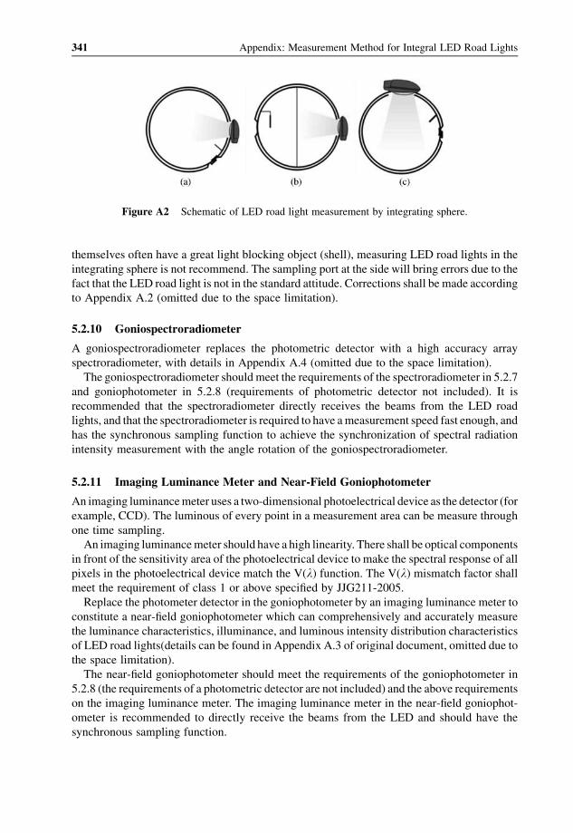
themselves often have a great light blocking object (shell), measuring LED road lights in the
integrating sphere is not recommend. The sampling port at the side will bring errors due to the
fact that the LED road light is not in the standard attitude. Corrections shall be made according
to Appendix A.2 (omitted due to the space limitation).
5.2.10 Goniospectroradiometer
A goniospectroradiometer replaces the photometric detector with a high accuracy array
spectroradiometer, with details in Appendix A.4 (omitted due to the space limitation).
The goniospectroradiometer should meet the requirements of the spectroradiometer in 5.2.7
and goniophotometer in 5.2.8 (requirements of photometric detector not included). It is
recommended that the spectroradiometer directly receives the beams from the LED road
lights, and that the spectroradiometer is required to have ameasurement speed fast enough, and
has the synchronous sampling function to achieve the synchronization of spectral radiation
intensity measurement with the angle rotation of the goniospectroradiometer.
5.2.11 Imaging Luminance Meter and Near-Field Goniophotometer
An imaging luminancemeter uses a two-dimensional photoelectrical device as the detector (for
example, CCD). The luminous of every point in a measurement area can be measure through
one time sampling.
An imaging luminancemeter should have a high linearity. There shall be optical components
in front of the sensitivity area of the photoelectrical device to make the spectral response of all
pixels in the photoelectrical device match the V(l) function. The V(l) mismatch factor shall
meet the requirement of class 1 or above specified by JJG211-2005.
Replace the photometer detector in the goniophotometer by an imaging luminance meter to
constitute a near-field goniophotometer which can comprehensively and accurately measure
the luminance characteristics, illuminance, and luminous intensity distribution characteristics
of LED road lights(details can be found in Appendix A.3 of original document, omitted due to
the space limitation).
The near-field goniophotometer should meet the requirements of the goniophotometer in
5.2.8 (the requirements of a photometric detector are not included) and the above requirements
on the imaging luminance meter. The imaging luminance meter in the near-field goniophot-
ometer is recommended to directly receive the beams from the LED and should have the
synchronous sampling function.
Figure A2 Schematic of LED road light measurement by integrating sphere.
341 Appendix: Measurement Method for Integral LED Road Lights

5.2.12 Temperature Controllable Thermostatic Chamber and MeasurementEquipment for Luminous Flux against Temperature Characteristics
The temperature controllable thermostatic chamber can make the measured LED road lights
operate in the chamber in required attitude. The controlled temperature is from �30 �C to
100 �C; temperature control accuracy is �3 �C; temperature measurement accuracy is �1 �C.The space in the chamber shall be large enough with an even temperature field. The tempera-
ture measurement point inside the chamber should be on the same horizontal level of the
photometry center, and 0.5meters away from the LED road lights. The temperature mea-
surement probe should not be directly illuminated.
The measurement equipment of luminous flux against temperature characteristics is
composed of a temperature controllable thermostatic chamber and measurement equipment
of relative changes of luminous flux in the test chamber and it has the recording function for the
relative values of luminous flux in different chamber temperature.
6 Measurement Methods
6.1 Measurement of the Basic Electrical Propertiesand Harmonic Current
Measure DC supplied externally controlled LED road lights by voltmeter and ammeter.
Voltage, current, power, power factor, frequency, and input harmonic current of LED road
lights (externally controlled LED road light being generally attached by a reference external
controller) are measured by a digital power meter with the function of measuring voltage,
current, power, power factor, frequency, and input current harmonic, and so on.
Because the voltage sampling connected in parallel has a certain by-pass current, and the
current sampling connected in series has a certain voltage drop, the application of the ammeter
internal connecting method or external connecting method is determined according to the
practical voltage and current of the measured LED road light. When the current is relatively
large, or the lead is relatively long, a quadric-pole method can be used for voltage sampling.
6.2 Test of Electromagnetic Compatibility
6.2.1 An RFI Emissions Test for Self-Ballasted LED Road Lights and Externally
Controlled LED Road Lights (Including Designated External Controller) is
Carried Out According to CISPR 15
6.2.2 An EMC Immunity Test for LED Road Lights is Carried Out According to the
Requirements of IEC 61547
6.3 Measurement of Luminous Flux and Luminous Efficacy
The measurement of luminous flux include the illuminance integration method, the luminous
intensity integrationmethod, and the substitutionmethod using an integrating sphere, in which
the illuminance integrationmethod can be used as referencemeasurement of the total luminous
flux for its high accuracy. When there is doubt about the total flux measured by the luminous
LED Packaging for Lighting Applications 342

intensity integration method or the integrating sphere method, the measurement result of
illumination integration should be preferred.
6.3.1 Reference Measurement Method of Total Luminous Flux
In the photometric dark room, measure the total luminous flux of an LED road light by
reference goniophotometer specified in 5.2.8.
Mount the LED road light within the reference goniophotometer for flux in the specified
burning attitude, and its photometric center should be as close to the rotation centre of the
goniophotometer as possible.
Measure the illuminance of the points on the surface of the imaginary sphere around
the LED road light in enough measuring planes with an angle step small enough. The angle
interval is generally 5� between planes and the angle steps in a plane is generally 1�. When the
size of the measured LED road light is relatively large or the beam angle is relatively narrow,
smaller plane intervals and angle steps are required to ensure complete sampling of
illuminance distribution.
The calculation equation of total luminous flux Ftot is:
Ftot ¼ð
ðStotÞ
EdS ¼ð4p
0
r2Eðe; ZÞdO ¼ð2p
0
ðp
0
r2Eðe; ZÞsin ededZ ðA1Þ
where r is the radius of the imaginary sphere, Stot is the total area of the imaginary sphere, and
(e, Z) is the space angle, as shown in Figure A3.
6.3.2 Measurement of Luminous Flux by Luminous Intensity Integration Method
In the photometric dark room, measure the spatial luminous intensity distribution of an LED
road light by a goniophotometer specified in 5.2.8, and calculate the total luminous flux,
regional luminous flux, and the upward (downward) luminous flux fraction of the LED road
light by the numerical integration method.
Figure A3 Schematic diagram of the calculation of luminous flux.
343 Appendix: Measurement Method for Integral LED Road Lights
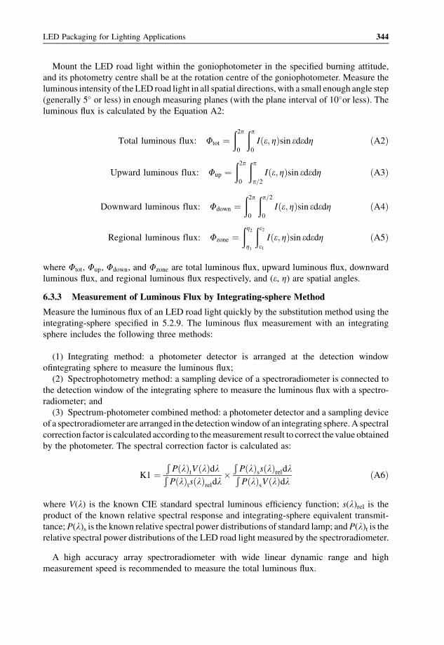
Mount the LED road light within the goniophotometer in the specified burning attitude,
and its photometry centre shall be at the rotation centre of the goniophotometer. Measure the
luminous intensity of the LED road light in all spatial directions, with a small enough angle step
(generally 5� or less) in enough measuring planes (with the plane interval of 10�or less). Theluminous flux is calculated by the Equation A2:
Total luminous flux: Ftot ¼ð2p
0
ðp
0
Iðe; ZÞsin ededZ ðA2Þ
Upward luminous flux: Fup ¼ð2p
0
ðp
p=2Iðe; ZÞsin ededZ ðA3Þ
Downward luminous flux: Fdown ¼ð2p
0
ðp=2
0
Iðe; ZÞsin ededZ ðA4Þ
Regional luminous flux: Fzone ¼ðZ2
Z1
ðe2
e1Iðe; ZÞsin ededZ ðA5Þ
where Ftot, Fup, Fdown, and Fzone are total luminous flux, upward luminous flux, downward
luminous flux, and regional luminous flux respectively, and (e, Z) are spatial angles.
6.3.3 Measurement of Luminous Flux by Integrating-sphere Method
Measure the luminous flux of an LED road light quickly by the substitution method using the
integrating-sphere specified in 5.2.9. The luminous flux measurement with an integrating
sphere includes the following three methods:
(1) Integrating method: a photometer detector is arranged at the detection window
ofintegrating sphere to measure the luminous flux;
(2) Spectrophotometry method: a sampling device of a spectroradiometer is connected to
the detection window of the integrating sphere to measure the luminous flux with a spectro-
radiometer; and
(3) Spectrum-photometer combined method: a photometer detector and a sampling device
of a spectroradiometer are arranged in the detectionwindowof an integrating sphere.A spectral
correction factor is calculated according to themeasurement result to correct thevalue obtained
by the photometer. The spectral correction factor is calculated as:
K1 ¼ÐP lð ÞtV lð ÞdlÐP lð Þts lð Þreldl
�ÐP lð Þss lð ÞreldlÐP lð ÞsV lð Þdl ðA6Þ
where V(l) is the known CIE standard spectral luminous efficiency function; s(l)rel is theproduct of the known relative spectral response and integrating-sphere equivalent transmit-
tance;P(l)s is the known relative spectral power distributions of standard lamp; andP(l)t is therelative spectral power distributions of the LED road light measured by the spectroradiometer.
A high accuracy array spectroradiometer with wide linear dynamic range and high
measurement speed is recommended to measure the total luminous flux.
LED Packaging for Lighting Applications 344

If there are large differences between the measured LED road light and the standard lamp in
shape and size, an auxiliary lamp is needed for the self absorption correction. And a stable LED
road light with good reproducibility, which has similar luminous intensity and spectrum
distribution with the measured one, are recommended to be the standard lamp for calibrating
the measuring instrument.
6.4 Measurement of Luminous Intensity Distribution and Beam Angle
In a photometric dark room, measure the luminous intensity distribution and beam angle of an
LED road light by a goniophotometer specified in 5.2.8.
The LED road light shall be mounted within the goniophotometer in the specified burning
attitude. Align the test LED road light with laser, or a more effective method, to make its
photometric centre exactly at the rotation centre of the goniophotometer. Take readings in the
specified measuring planes with an angle step less than 1/20 of the half peak side angle.
6.5 Measurement of Flashed Area and Average Luminanceof an LED Road Light
6.5.1 Simple Method for Flashed Area and Average Luminance
The flashed area can be measured by the following method: place a closed rectangle frame on
front of the test LED as close as possible; the four sides of the frame aremovable by sliding and
the frame size is bigger than the lighting area of the LED road light. Read the luminous intensity
of the LED road light in the direction of C¼ 0�, g¼ 76�, when there is no blockage in front ofthe LED light. Then move each side of the rectangular box slowly towards the lighting area,
until the new reading after every slide is 0.98 of its latest. The left area of the rectangular frame
is the so called “flashed area”.
Calculate the average luminance in the 76� direction in theC0� andC180� plane according tothe measurement result of luminous intensity in 6.4 of this appendix.
Lð0�=180�; 76�Þavg ¼Ið0�=180�; 76�Þ
Aflashð0�=180�; 76�Þ ðA7Þ
where Lð0�=180�; 76�Þavg is the average luminance in the flashed area; Ið0�=180�; 76�Þ is theluminous intensity in the direction of flashed area; Aflashð0�=180�; 76�Þ is the luminous area of
LED road light.
6.5.2 Measurement of Flashed Area and Luminance Characters by Imaging
Luminance Meter
Measure the luminance distribution of an LED road light in the 76� direction in C0� and C180�
planes by a near-field goniophotometer or an image luminance photometer. The photosensitive
surface of the imaging luminance photometer should directly facethe LED road light with its
optical axis passes through the photometry center of the LED road light. Determine the flashed
area with the same principle as described in the simple method. Calculate the average
luminance and maximum luminance of the LED road light in the flashed area.
345 Appendix: Measurement Method for Integral LED Road Lights

6.6 Measurement of Colorimetric Performance
6.6.1 Measurement of Colorimetric Performance by Goniospectroradiometer
In the photometric dark room, measure the colorimetric quantities of an LED road light by a
goniospectroradiometer, as specified in 5.2.10.
The LED road light shall be mounted within a goniospectroradiometer in the specified burn-
ing attitude, and its light centre should bemounted at the rotation centre of the goniophotometer.
Measure the relative spectral power distributions of the LED road light in all directions on
enough luminous planes with small enough angle steps. The angle interval between measuring
planes is generally 10� and the angle step i is generally 5�. When the size of the measured LED
road light is relatively large or the beam angle is relatively narrow, smaller plane intervals and
angle steps should be applied. Calculate the colorimetric quantities in all spatial directions
according toCIE15-2004; the quantities of theLEDroad light include: chromaticity coordinates,
correlated color temperature, color rendering index, color tolerance, and so on. The average
colorimetric quantities of an LED road light are calculated by the numerical method.
6.6.2 Measurement of Average Color by Integrating Sphere
It is convenient to measure the average colorimetric quantities of an LED road light by the
substitutionmethodwith an integrating spectroradiometer. Themeasurementmethod is similar
to measuring the luminous flux by the integrating sphere method.
Calibrate the integrating spectroadiometer by a standard spectral radiant flux lamp.
6.6.3 Measurement of Color Non-uniformity
The colorimetric quantities are measured in various spatial directions of the LED road light
according to 6.6.1. Calculated the average color non-uniformity and the maximum color non-
uniformity according to their definition.
6.7 Measurement of Luminous Flux Property Against Temperature
The relative measurement method can be used to measure the luminous flux property against
temperature. Operate the measured LED road light in a temperature controllable thermostatic
chamber at its standardmeasurement attitude, under the specified voltage/current/power or the
maximum value in the range of the specified voltage/current/power. Control the temperature in
the chamber to make it increase from the minimum temperature of allowable ambient
temperature range. The change of relative luminous flux is measured at interval of five when
the LED road light has been stable at least for 15minutes at the temperature. Take the luminous
flux value at 25�C as 100%, and record the relative changes of luminous flux at each
temperatures. If there is no specific requirement, the maximum temperature in the measure-
ment is the maximum ambient temperature in the range of allowable ambient temperature for
LED road light.
6.8 Test of Maximum Allowable Ambient Temperature
Operate the LED road light in a temperature controllable thermostatic chamber at its standard
attitude and at the maximum allowable ambient temperature for 100 hours. There should be no
LED Packaging for Lighting Applications 346

mechanical damage of any component, no abnormality of any LED, and the luminous flux of
the measured LED road light should be better than 95% of rated value when returned back to
25�C ambient temperature.
6.9 Test of Endurance of High-Low Temperature Cycling Behavior
Operate an LED road light in a temperature controllable thermostatic chamber at its standard
measurement attitude, and under the specified voltage or themaximumvalue in the range of the
specified voltage. Control the temperature of the chamber to make it rise from the room
temperature to 50 �C and keep it at this temperature for 16 hours. Then drop the temperature to
�5 �C and keep it at this temperature for 16 hours, consequently, rise the temperature to the
room temperature again. The rate of the temperature changing is 0.5 �C/min to 1 �C/min. After
two such cycles, there should be no mechanical damage to any component of the LED road
light, no abnormality should occur for any LED, and the luminous flux of the measured LED
road light should be higher than 95% of rated value.
6.10 Measurement of Light Maintenance
The lightmaintenance propertymeasurement includes themeasurement of lumenmaintenance
and color shift.
LED road light is subjected to aging under specified conditions, until at least 6000 hours,
with the both the total luminous flux and the chromaticity parameters recorded at least every
1000 hours. The quantities measured after 1000 hours shall be compared with the value obtain
at 1000 hours. To simplify the measurement, the illuminance at a given right downward point
can be used to replace the total luminous flux of the LED road light for the calculation of lumen
maintenance, and the color sift can be expressed by the coordinate difference of ðu0; v0Þ in CIE1976 according to CIE 15-2004.
It is suggested that LED road light continues operating to eliminate the possible influence
cause by on/off modulation. During the aging testing, care should be exercised to examine or
automatically monitor if the LED road light fails. If failure occurs, an examination should be
performed to check if the LED road light really fails, or if the failure is caused by other auxiliary
or fixtures.
6.11 Test of On/Off Characteristics
Under the specified operation conditions, a switching cycle is defined to be 30 seconds open and
30 seconds off. Repeat the switching cycle until the specified number of cycles is reached. The
LED road light is expected to operate normally after the cycles.
347 Appendix: Measurement Method for Integral LED Road Lights