led photoelectric effect apparatus -...
TRANSCRIPT

LED Photoelectric Effect Apparatus designed by Wayne Garver, University of Missouri, St. Louis
Albert Einstein’s interpretation of the photoelectric effect was central to the development of the photon model of light and 20th century physics. For $60-80, this is the most inexpensive way for students to use an actual photoelectric effect apparatus to explore the photoelectric experiment and find Planck’s constant. This document contains apparatus photos, an apparatus diagram, a schematic diagram, parts list/ordering information, required tools, construction template, LED organizer template, and assembly instructions.
A light shield, made from a cardboard box to cover the phototube and LED Bracket, is not pictured here. The light shield blocks extraneous light from the room.

LED Photoelectric Effect Apparatus Parts list Wayne Garver, University of Missouri, St. Louis
Qty Item Source/stk # $(each) 1 1P39 or 939 Phototube www.vacuumtubes.net 30-50 www.thetubestore.com www.superbrightleds.com 1 405 nm (UV) LED RL5-UV2030 1.79 1 463 nm (blue) LED RL5-B3023 1.04 1 505 nm (aqua) LED RL5-A9018 1.29 1 525 nm (green) LED RL5-G8020 1.29 1 593 nm (yellow) LED RL5-Y5615 0.49 1 605 nm (orange) LED RL5-O5015 0.54 1 631 nm (red) LED RL5-R5015 0.49 1 880 nm (IR) LED RL5-IR2030 1.29 1 945 nm (IR) LED RL5-IR2730 1.29 www.mouser.com 1 8 pin tube socket 655-27E122 4.70 1 2.5k Potentiometer 31VA303 1.25 1 4.6x6.1x2.2 plastic box 563-CU-3283-MB 11.20 1 On/off switch 108-MS550K 1.50 1 LED connector with 180 Ohm resistor 593-CNX3310-018-X2108 2.35 1 10k ¼ watt resistor 660-MF1/4DL1002F 0.03 1 100k ¼ watt resistor 660-MF1/4DL1003F 0.03 2 Red banana jacks 530-111-0103-001 1.54 2 Black banana jacks 530-111-0102-001 1.54 1 9V battery clip 121-0526/T 0.27 1 4C battery holder 12BH243 1.08 1 Knob 45KN026 0.81 2 Digital multimeters – microamp resolution 1 1-1/4” x 3-1/4” L-shaped holder with 13/64”
hole for LED (i.e. cut from plastic box)
1 Light shield for phototube 1 3/8” #8 sheet metal screw 3 ½” #8-32 machine bolts 3 #8-32 nuts 4 C-cells 1 9 Volt battery 1 Package of 3/8”x5/8” labels to mark LED’s 1 Set of markers to color code LED labels 6 3”-6” jumper wires 1 Photocopied drilling template 1 Printout of LED color/wavelengths Electrical tape Double sided mounting tape
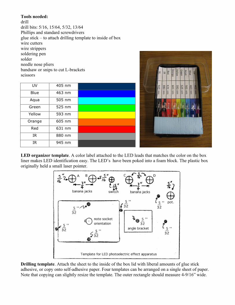
Tools needed: drill drill bits: 5/16, 15/64, 5/32, 13/64 Phillips and standard screwdrivers glue stick – to attach drilling template to inside of box wire cutters wire strippers soldering pen solder needle nose pliers bandsaw or snips to cut L-brackets scissors
UV 405 nm
Blue 463 nm
Aqua 505 nm
Green 525 nm
Yellow 593 nm
Orange 605 nm
Red 631 nm
IR 880 nm
IR 945 nm
LED organizer template. A color label attached to the LED leads that matches the color on the box liner makes LED identification easy. The LED’s have been poked into a foam block. The plastic box originally held a small laser pointer.
Drilling template. Attach the sheet to the inside of the box lid with liberal amounts of glue stick adhesive, or copy onto self-adhesive paper. Four templates can be arranged on a single sheet of paper. Note that copying can slightly resize the template. The outer rectangle should measure 4-9/16” wide.

Constructing the Photoelectric Effect Apparatus Group Activities: [] Securely glue a template centered on the inside of the project box lid. [] Drill the holes at the positions indicated. [] Attach labels to LED’s and color code with markers [] Make corresponding color codes for box liner. [] Clip off black end of LED connector wires and strip wire ends [] Cut jumper wires and strip ends [] Cut plastic boxes into 1-1/4” x 3-1/4” L-shaped pieces and drill holes. Individual steps: Clean burrs out of holes and install the following parts: [] Red Binding posts in holes A & C [] Black binding posts in holes B & D [] Attach the phototube socket with bolts and nuts – observe orientation of socket notch [] install switch and potentiometer as shown in photo; attach knob to pot [] Attach C-cell battery holder to box bottom with sheet metal screw [] Attach L-bracket with bolt and nut [] Label binding posts on the top of the panel: “Stopping potential” for posts A&B, “Photoelectric Current” for posts C&D, “on” position for switch Prepare wiring for soldering: [] Attach 100K resistor between binding posts C&D [] Attach 10K resistor to switch as shown in picture, jumper from resistor to right side of pot [] attach 9V battery wires, red to switch center, black to post B [] poke LED socket wires through hole on right side of picture, connect to C-cell battery holder wires (black to black and red to white) [] jumper wire from phototube socket pin 8 to binding post A [] jumper wire from phototube socket pin 4 to binding post C [] jumper from A to pot center [] jumper from B to pot left [] jumper from B to D [] solder all connections [] install batteries, attach 9V battery to box bottom with double-sided mounting tape [] install phototube [] connect meters and test [] Screw lid onto box [] Make cardboard light shield