leds and resistors -...
TRANSCRIPT

LEDs and Resistors Page 1 of 15 Developed by IEEE as part of TryEngineering
www.tryengineering.org
LEDs and Resistors
Provided by TryEngineering - www.tryengineering.org
L e sso n Fo cus Expanding on understanding of simple circuits, this lesson explores LEDs and resistors and reviews the differences between parallel and series circuit design and functions. Note: This lesson plan is designed for classroom use only, with supervision by a teacher familiar with electrical and electronic concepts. (Note: For older or more advanced students, consider using TryEngineering’s Voltage Divider or Ohm’s Law lessons.)
L e sso n Syno p s is The LEDs and Resistors activity encourages students to build a simple circuit on a breadboard using simple electrical components including LEDs and resistors. Students work in teams to predict and test how different resistors impact LED brightness. After testing several predictions about each circuit type, the groups will compare results and discuss findings. Advanced students may also explore and test on the breadboard how arranging LEDs in parallel and series impact brightness.
Ag e L e ve ls 8-12
O b je c t ive s
Learn about LEDs, their application and history. Learn about resistors and their function in electrical circuitry. Learn about current flow and the operational differences between series and parallel
circuits. Learn to predict outcomes and draw conclusions. Learn about teamwork and working in groups.
Ant ic ip a te d L e a r ne r O utco me s As a result of this activity, students should develop an understanding of:
LEDs Resistor functions parallel and series circuits circuits and current flow making and testing predictions teamwork

LEDs and Resistors Page 2 of 15 Developed by IEEE as part of TryEngineering
www.tryengineering.org
L e sso n Ac t iv it ie s
Students learn how to wire on a simple breadboard and explore the impact of various resistors on LED brightness. Advanced students work in teams to experiment with variances in series and parallel wiring of LED circuits and make predictions about how the design of the circuit will impact LED brightness.
Alig nme n t to C ur r icu lu m Fr a me w o r ks See attached curriculum alignment sheet.
In te r ne t C o nne ct io ns
TryEngineering (www.tryengineering.org) Next Generation Science Standards (www.nextgenscience.org) Common Core State Standards for Mathematics (www.corestandards.org/Math) International Technology Education Association's Standards for Technological
Literacy (www.iteea.org/39161.aspx) Computer Science Teachers Association K-12 Computer Science Standards
(www.csteachers.org/page/standards)
R e co mme nd e d R e a d ing
DK Eyewitness Books: Electricity (ISBN: 978-1465408990) Electronics for Kids: Play with Simple Circuits (ISBN: 978-1593277253) Teach Yourself Electricity and Electronics (ISBN: 978-1259585531)
O p t io na l W r it ing Ac t iv it y
Write an essay (or paragraph depending on age) describing how the invention of LEDs have impacted the design of everyday products. Consider the energy efficiency of LEDs in your discussion.

LEDs and Resistors Page 3 of 15 Developed by IEEE as part of TryEngineering
www.tryengineering.org
LEDs and Resistors
Fo r T e a che r s : T e a che r R e so ur ce s
Lesson Goal The LEDs and Resistors activity encourages students to build a simple circuit on a breadboard using simple electrical components including LEDs and resistors. Students work in teams to predict and test how different resistors impact LED brightness. After testing several predictions about each circuit type, the groups will compare results and discuss findings. Advanced students may also explore and test on the breadboard how arranging LEDs in parallel and series impact brightness.
Lesson Objectives Learn about LEDs, their application and history. Learn about resistors and their function in electrical circuitry. Learn about current flow and the operational differences between series and parallel
circuits. Learn to predict outcomes and draw conclusions. Learn about teamwork and working in groups.
Materials
Student Resource Sheets Student Worksheet Set of materials for each team of students (see parts
suggestions below): o Battery clip connector o 9V battery o Assortment of LEDs (different colors) o Assortment of resistors (330Ω, 1KΩ, 2KΩ,
5KΩ, 10KΩ, 100KΩ – NOT below 330Ω) o Simple solderless breadboard
Materials can be bought in sets inexpensively online or at a local electronics store.
Procedure
1. Provide students with reference sheets on simple circuits and series and parallel circuits, perhaps as homework reading on the night prior to the activity.
2. Divide students into teams of 3-4 students and distribute Student Worksheets and materials to each group.
3. Have each team draw a schematic of a simple circuit using a resistor and LED and then build this circuit on a breadboard. Be sure each student has a chance to place wires and have hands on experience.
4. Challenge students to try different resistors and observe and document the impact on the LED.
5. Bring the student groups together to discuss their findings.
LEDs and Resistors Page 4 of 15 Developed by IEEE as part of TryEngineering
www.tryengineering.org
Optional Advanced Activity
For extension or advanced students:
1. Challenge the students to predict what will happen to the LED brightness if they incorporate two LEDs into their design in a series circuit. Teams then test their hypothesis and observe the resulting brightness of the LEDs.
2. Challenge the students to predict what will happen to the LED brightness if they incorporate two LEDs into their design in a parallel circuit. Teams then test their hypothesis and observe the resulting brightness of the LEDs.
Time Needed 45 Minutes
Tips
Teacher should supervise the lesson and be sure that students are clear on correct placement of LED leads to avoid damaging parts.
Teachers should consider distributing the student resource sheets as reading material/homework for the night before the activity will be conducted in class.
Resistors can get warm or even hot when in use. The range suggested in this lesson is selected to reduce warmth. Do not use resistors below 330Ω (ohm) for this lesson. Have students wire the board and then connect the battery. Then allow the resistor to cool off for a few minutes before rewiring.
The longer lead on an LED must be the first in sequence in the path of current. In batches, expect one or two defective LEDs, so provide additional to each student
team. For older or more advanced students, consider using TryEngineering’s Voltage
Divider or Ohm’s Law lessons.

LEDs and Resistors Page 5 of 15 Developed by IEEE as part of TryEngineering
www.tryengineering.org
LEDs and Resistors
Fo r T e a che r s : T e a che r R e so ur ce s
Sample Diagrams: The following are sample diagrams to support the lesson or serve as examples to students:
Simple circuit with LED:
Single LED in Parallel Circuit:
Single LED in Series Circuit:
LEDs and Resistors Page 6 of 15 Developed by IEEE as part of TryEngineering
www.tryengineering.org
LEDs and Resistors
Fo r T e a che r s : T e a che r R e so ur ce s
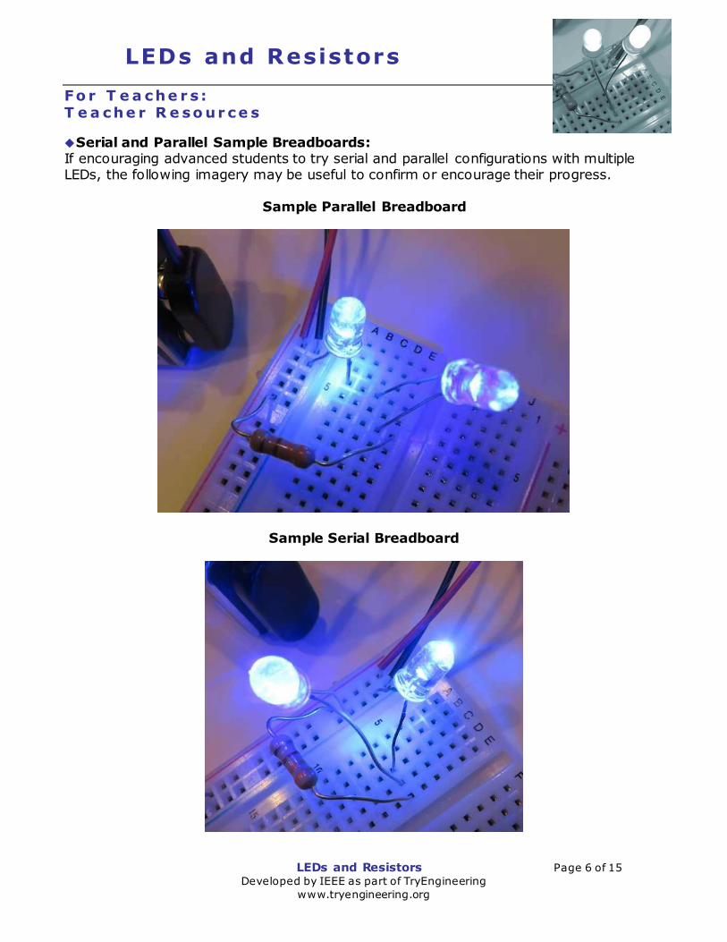
Serial and Parallel Sample Breadboards: If encouraging advanced students to try serial and parallel configurations with multiple LEDs, the following imagery may be useful to confirm or encourage their progress.
Sample Parallel Breadboard
Sample Serial Breadboard

LEDs and Resistors Page 7 of 15 Developed by IEEE as part of TryEngineering
www.tryengineering.org
LEDs and Resistors
Stud e nt R e so ur ce : W ha t is a S imp le C ir cu it ?
Simple Circuit
A simple circuit consists of three elements: a source of electricity (battery), a path or conductor on which electricity flows (wire) and an electrical load (lamp) which is any device that requires electricity to operate. The illustration below shows a simple circuit containing a battery, two wires, and a low voltage light bulb. The flow of electricity is caused by excess electrons on the negative end of the battery flowing toward the positive end, or terminal, of the battery. When the circuit is complete, electrons flow from the negative terminal through the wire conductor, then through the bulb (lighting it up), and finally back to the positive terminal - in a continual flow.
Schematic Diagram of a Simple Circuit The following is a schematic diagram of the simple circuit showing the electronic symbols for the battery, switch, and bulb.
LEDs and Resistors Page 8 of 15 Developed by IEEE as part of TryEngineering
www.tryengineering.org
LEDs and Resistors
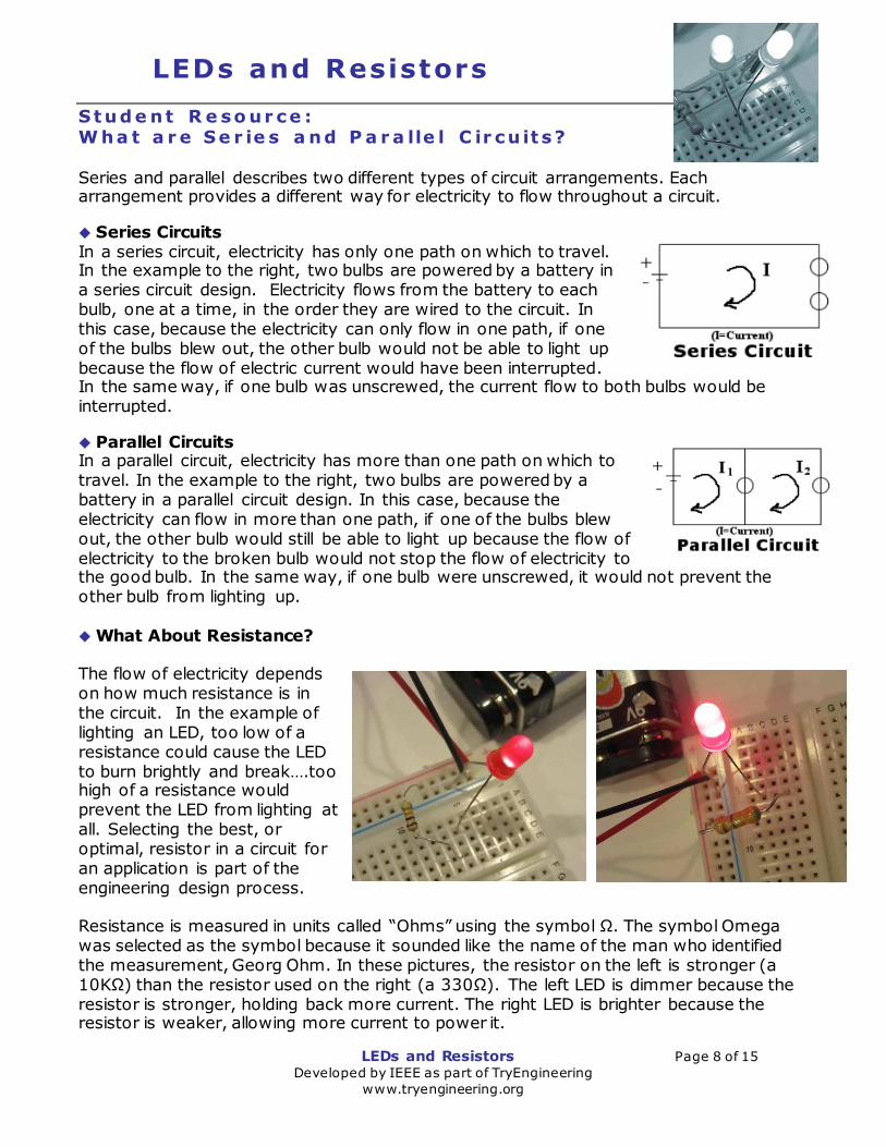
Stud e nt R e so ur ce : W ha t a r e Se r ie s a nd P a r a lle l C ir cu it s? Series and parallel describes two different types of circuit arrangements. Each arrangement provides a different way for electricity to flow throughout a circuit.
Series Circuits In a series circuit, electricity has only one path on which to travel. In the example to the right, two bulbs are powered by a battery in a series circuit design. Electricity flows from the battery to each bulb, one at a time, in the order they are wired to the circuit. In this case, because the electricity can only flow in one path, if one of the bulbs blew out, the other bulb would not be able to light up because the flow of electric current would have been interrupted. In the same way, if one bulb was unscrewed, the current flow to both bulbs would be interrupted.
Parallel Circuits In a parallel circuit, electricity has more than one path on which to travel. In the example to the right, two bulbs are powered by a battery in a parallel circuit design. In this case, because the electricity can flow in more than one path, if one of the bulbs blew out, the other bulb would still be able to light up because the flow of electricity to the broken bulb would not stop the flow of electricity to the good bulb. In the same way, if one bulb were unscrewed, it would not prevent the other bulb from lighting up. What About Resistance? The flow of electricity depends on how much resistance is in the circuit. In the example of lighting an LED, too low of a resistance could cause the LED to burn brightly and break….too high of a resistance would prevent the LED from lighting at all. Selecting the best, or optimal, resistor in a circuit for an application is part of the engineering design process. Resistance is measured in units called “Ohms” using the symbol Ω. The symbol Omega was selected as the symbol because it sounded like the name of the man who identified the measurement, Georg Ohm. In these pictures, the resistor on the left is stronger (a 10KΩ) than the resistor used on the right (a 330Ω). The left LED is dimmer because the resistor is stronger, holding back more current. The right LED is brighter because the resistor is weaker, allowing more current to power it.
LEDs and Resistors Page 9 of 15 Developed by IEEE as part of TryEngineering
www.tryengineering.org
LEDs and Resistors
Stud e nt R e so ur ce : W ha t a r e L E Ds?
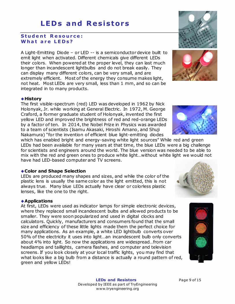
A Light-Emitting Diode – or LED -- is a semiconductor device built to emit light when activated. Different chemicals give different LEDs their colors. When powered at the proper level, they can last much longer than incandescent lightbulbs and do not break easily. They can display many different colors, can be very small, and are extremely efficient. Most of the energy they consume makes light, not heat. Most LEDs are very small, less than 1 mm, and so can be integrated in to many products. History The first visible-spectrum (red) LED was developed in 1962 by Nick Holonyak, Jr. while working at General Electric. In 1972, M. George Craford, a former graduate student of Holonyak, invented the first yellow LED and improved the brightness of red and red-orange LEDs by a factor of ten. In 2014, the Nobel Prize in Physics was awarded to a team of scientists (Isamu Akasaki, Hiroshi Amano, and Shuji Nakamura) “for the invention of efficient blue light-emitting diodes which has enabled bright and energy-saving white light sources" While red and green LEDs had been available for many years at that time, the blue LEDs were a big challenge for scientists and engineers around the world. The blue version was needed to be able to mix with the red and green ones to produce white light…without white light we would not have had LED-based computer and TV screens.
Color and Shape Selection LEDs are produced many shapes and sizes, and while the color of the plastic lens is usually the same color as the light emitted, this is not always true. Many blue LEDs actually have clear or colorless plastic lenses, like the one to the right.
Applications At first, LEDs were used as indicator lamps for simple electronic devices, where they replaced small incandescent bulbs and allowed products to be smaller. They were soon popularized and used in digital clocks and calculators. Quickly, manufacturers and consumers found that the small size and efficiency of these little lights made them the perfect choice for many applications. As an example, a white LED lightbulb converts over 50% of the electricity it uses into light…an incandescent bulb only converts about 4% into light. So now the applications are widespread…from car headlamps and taillights, camera flashes, and computer and television screens. If you look closely at your local traffic lights, you may find that what looks like a big bulb from a distance is actually a round pattern of red, green and yellow LEDs!

LEDs and Resistors Page 10 of 15 Developed by IEEE as part of TryEngineering
www.tryengineering.org
LEDs and Resistors
Stud e nt R e so ur ce : W ha t a r e R e s is to r s?
A resistor limits or resists the electrical current that flows through a circuit. The energy of the electrons that pass through a resistor are changed to heat and/or light…so less current is available to whatever device (an LED for example) is next on the circuit. In working with this lesson, the resistors will become warm because they are converting electrical energy to heat. We have selected resistors that will be very safe to use but it is wise to not touch the resistor for a couple of minutes after disconnecting the circuit so they have a chance to cool. Resistors are used in many different ways, frequently to protect components in a circuit from damage. In this lesson, the LEDs would likely burn out or break if put in a circuit without a resistor to protect them. Standards in Color Coding Resistors Identifying a resistor is an important skill when building a circuit. You have to know how a resistor will behave in a circuit. There are international standards so that engineers can assume consistency between parts. A resistor's value is determined by the colors that are printed on it in bands of some combination of black, brown, red, orange, yellow, green, blue, purple, gray, or white. Each color represents a different number as shown below:
The last band on a resistor indicates tolerance, which is how accurate the resistor is. For
example, a gold band represents a positive or negative 5% tolerance, while the silver band represents a positive or negative 10% tolerance.
silver ±10% gold ±5% red ±2%
brown ±1% If no fourth band is shown the tolerance is ±20%
Reading from left to right, the resistor shown has orange, orange, brown, then gold. The first two bands represent the numbers in the box above, so for the resistor in the photo we read 3 (for orange) and 3 (for orange). The last band gives the number of zeros to add at the end. For this resister because it is brown (1), we add just one zero to indicate a 330Ω (ohm) resistor, with a 5% tolerance.
0 - black
1 - brown
2 – red
3 – orange
4 – yellow
5 – green
6 – blue
7 – purple
8 – gray
9 - white
LEDs and Resistors Page 11 of 15 Developed by IEEE as part of TryEngineering
www.tryengineering.org
LEDs and Resistors
Stud e nt R e so ur ce : S imp le B r e a d b o a r d C ir cu it s
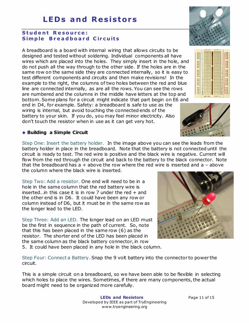
A breadboard is a board with internal wiring that allows circuits to be designed and tested without soldering. Individual components all have wires which are placed into the holes. They simply insert in the hole, and do not push all the way through to the other side. If the holes are in the same row on the same side they are connected internally, so it is easy to test different components and circuits and then make revisions! In the example to the right, the columns of two holes between the red and blue line are connected internally, as are all the rows. You can see the rows are numbered and the columns in the middle have letters at the top and bottom. Some plans for a circuit might indicate that part begin on E6 and end in D4, for example. Safety: a breadboard is safe to use as the wiring is internal, but avoid touching the connected ends of the battery to your skin. If you do, you may feel minor electricity. Also don’t touch the resistor when in use as it can get very hot. Building a Simple Circuit Step One: Insert the battery holder. In the image above you can see the leads from the battery holder in place in the breadboard. Note that the battery is not connected until the circuit is ready to test. The red wire is positive and the black wire is negative. Current will flow from the red through the circuit and back to the battery to the black connector. Note that the breadboard has a + above the row where the red wire is inserted and a – above the column where the black wire is inserted. Step Two: Add a resistor. One end will need to be in a hole in the same column that the red battery wire is inserted…in this case it is in row 7 under the red + and the other end is in D6. It could have been any row or column instead of D6, but it must be in the same row as the longer lead to the LED. Step Three: Add an LED. The longer lead on an LED must be the first in sequence in the path of current. So, note that this has been placed in the same row (6) as the resistor. The shorter end of the LED has been placed in the same column as the black battery connector, in row 5. It could have been placed in any hole in the black column. Step Four: Connect a Battery. Snap the 9 volt battery into the connector to power the circuit. This is a simple circuit on a breadboard, so we have been able to be flexible in selecting which holes to place the wires. Sometimes, if there are many components, the actual board might need to be organized more carefully.

LEDs and Resistors Page 12 of 15 Developed by IEEE as part of TryEngineering
www.tryengineering.org
LEDs and Resistors
Stud e nt W o r kshe e t : Planning You are a team of engineers and need to design and build a simple breadboard circuit that will power an LED. Then you’ll perform some experiments to help you learn about LEDs and resistors. You have been provided with several parts…including a breadboard, a battery and battery holder, some LEDs and some resistors. You’ll need a resistor to protect the LED from receiving current directly from the battery which would burn it out. In the box below using appropriate electronic symbols, draw your planned circuit. Be sure to draw arrows showing the direction of current flow. ELECTRONIC SYMBOLS:
LED: Resistor: Battery:
Construction Once your teacher has reviewed your plan, you can begin to construct your breadboard circuit. A few tips: 1. The longer wire (or lead) on any LED should be attached to the positive side of the battery or circuit. 2. Current can only flow through the LED in one direction in this lesson. 3. Choose a 10kΩ resistor for the initial breadboard. 3. Attach the battery after your teacher has approved your breadboard. 4. Once the battery is attached, don’t touch the resistor as it may be warm or hot. It will cool within a minute or two after detaching battery. If your LED was powered and lights up, you are ready to move on to the testing phase!

LEDs and Resistors Page 13 of 15 Developed by IEEE as part of TryEngineering
www.tryengineering.org
LEDs and Resistors
Stud e nt W o r kshe e t : Hypothesis Now that your basic LED was powered, what do you think would happen if you used a different strength resistor? Consider your LED brightness in the initial test as a “5.” Make predictions in the box below:
Strength of Resistor (Ω = OHMs)
Observed LED brightness (scale 0-10, 10 brightest)
Anticipated LED brightness (scale 0-10, 10 brightest)
330Ω ?
2kΩ ? 5kΩ ?
10kΩ 5 100kΩ ?
Testing With your predictions in the box above, switch the resistors to see what happens to the LED. BE SURE TO WAIT FOR TWO MINUTES AFTER THE BATTERY IS DETACHED BEFORE TOUCHING THE RESISTOR AS IT CAN BE WARM OR HOT.
Strength of Resistor (Ω = OHMs)
Observed LED brightness (scale 0-10, 10 brightest)
330Ω
2kΩ 5kΩ
10kΩ 5 100kΩ
Reflection Answer the questions below: 1. How close was your hypothesis to the actual result of your resistor testing? 2. What surprised you about the results? 3. If this LED was designed into a doorbell, which level of resistor would you think the best choice? Why? 4. Did you find that any of your component parts malfunctioned? What happened? Do you think you received a defective part?

LEDs and Resistors Page 14 of 15 Developed by IEEE as part of TryEngineering
www.tryengineering.org
LEDs and Resistors
Fo r T e a che r s : A lig nme n t to C ur r icu lu m S ta nd a r d s All lesson plans in this series are aligned to the Next Generation Science Standards, and if applicable also to the Computer Science Teachers Association K-12 Computer Science Standards, the U.S. Common Core State Standards for Mathematics, and the International Technology Education Association's Standards for Technological Literacy.
Next Generation Science Standards (grades 3-5, middle school) Students who demonstrate understanding can:
3-5-ETS1-1. Define a simple design problem reflecting a need or a want that
includes specified criteria for success and constraints on materials, time, or cost.
3-5-ETS1-2. Generate and compare multiple possible solutions to a problem based
on how well each is likely to meet the criteria and constraints of the problem.
3-5-ETS1-3. Plan and carry out fair tests in which variables are controlled and
failure points are considered to identify aspects of a model or prototype that can be
improved.
4-PS3-2. Make observations to provide evidence that energy can be transferred
from place to place by sound, light, heat, and electric currents.
4-PS3-4. Apply scientific ideas to design, test, and refine a device that converts
energy from one form to another.
MS-ETS1-1. Define the criteria and constraints of a design problem with sufficient
precision to ensure a successful solution, taking into account relevant scientific
principles and potential impacts on people and the natural environment that may
limit possible solutions.
MS-ETS1-2. Evaluate competing design solutions using a systematic process to
determine how well they meet the criteria and constraints of the problem.
MS-ETS1-3. Analyze data from tests to determine similarities and differences
among several design solutions to identify the best characteristics of each that can
be combined into a new solution to better meet the criteria for success.
MS-ETS1-4. Develop a model to generate data for iterative testing and modification
of a proposed object, tool, or process such that an optimal design can be achieved.
U.S. Common Core State Standards for Mathematics (grades 3-5)
Grade Three: Represent and Interpret Data (CCSS.MATH.CONTENT.3.MD.B.4)
Grade Four: Represent and Interpret Data (CCSS.MATH.CONTENT.4.MD.B.4)
Grade Five: Represent and Interpret Data (CCSS.MATH.CONTENT.5.MD.B.2)
LEDs and Resistors Page 15 of 15 Developed by IEEE as part of TryEngineering
www.tryengineering.org
LEDs and Resistors
Fo r T e a che r s : A lig nme n t to C ur r icu lu m S ta nd a r d s ( co nt . )
International Technology Education Association's Standards for Technological Literacy (grades 3-5)
Chapter 8 – The Attributes of Design
o Definitions of Design
o Requirements of Design
Chapter 9 – Engineering Design
o Engineering Design Process
o Creativity and Considering all ideas
o Models
Chapter 10 – The Role of Troubleshooting, Research and Development, Invention,
and Experimentation in Problem Solving
o Troubleshooting
o Invention and innovation
o Experimentation
Chapter 11 – Apply the Design Process
o Collect information
o Visualize a solution
o Test and evaluate solutions
o Improve a design
Chapter 16 – Energy and Power Technologies
o Energy comes in different forms
o Tools, machines, products and systems