leroy-somer poulibloc 2000-3000 - installation - ref. … · 1.1.6 - implantation du moteur la...
TRANSCRIPT

POULIBLOC 2000-3000
InstallationInbetriebnahmeInstalación
Réducteur à montage pendulaire Shaft mount reducer Wellenmontiertes GetriebeReductor de montajependular
Référence : 3097 lg - 2017.08 / f
enfr
dees


POULIBLOC 2000-3000
Guide d’installation
Réducteur à montage pendulaire
Référence : 3097 fr - 2017.08 / f
fr

4
Guide d'installation - POULIBLOC 2000-30003097 fr - 2017.08 / f
Ce document vient en complément à la notice générale réf. 2557 (recommandations),réf. 3711 (recommandations spécifiques ATEX) et à la notice maintenance Poulibloc 2000-3000 réf. 5069.
NOTELEROY-SOMER se réserve le droit de modifier les caractéristiques de ses produits à tout moment pour y apporter les derniers développements technologiques. Les informations contenues dans ce document sont donc susceptibles de changer sans avis préalable.LEROY-SOMER ne donne aucune garantie contractuelle quelle qu’elle soit en ce qui concerne les informations publiées dans ce document et ne sera tenu pour responsable des erreurs qu’il peut contenir, ni des dommages occasionnés par son utilisation.
ATTENTIONLes prescriptions, instructions et descriptions concernent l’exécution standard. Elles ne tiennent pas compte de variantes de construction ou des adaptations spéciales. Le non respect de ces recommandations peut entraîner une détérioration prématurée du réducteur et la non application de la garantie du constructeur.
Ce symbole signale dans la notice des avertissements concernant les conséquences dues à l’utilisation inadaptée du Poulibloc 2000-3000, les risques pouvant entraîner des dommages matériels ou corporels.
Malgré tout le soin apporté à la fabrication et au contrôle de ce matériel, LEROY-SOMER ne peut garantir à vie l’absence de fuite de lubrifiant. Au cas où de légères fuites pourraient avoir des conséquences graves mettant en jeu la sécurité des biens et des personnes, il appartient à l’installateur et à l’utilisateur de prendre toutes les précautions nécessaires pour éviter ces conséquences.
SOMMAIRE
1 - POULIBLOC 2000 ..................................................................................................................51.1 - Recommandations d’installation .................................................................................................................... 5
1.1.1 - Identification ........................................................................................................................................... 51.1.2 - Montage de la bague conique ................................................................................................................ 51.1.3 - Montage du réducteur ............................................................................................................................ 61.1.4 - Montage de la poulie sur l’arbre primaire ................................................................................................ 61.1.5 - Montage du bras de réaction .................................................................................................................. 61.1.6 - Implantation du moteur .......................................................................................................................... 61.1.7 - Montage de l’arbre creux cylindrique avec l’arbre de la machine à entraîner ......................................... 7
1.1.8 - Montage de l’antidévireur ....................................................................................................................... 81.2 - Lubrification ................................................................................................................................................... 8
1.2.1 - Position des bouchons ........................................................................................................................... 8
1.2.2 - Quantité d’huile ...................................................................................................................................... 91.3 - Entretien ........................................................................................................................................................ 9
2 - POULIBLOC 3000 ................................................................................................................102.1 - Recommandations d’installation .................................................................................................................. 10
2.1.1 - Identification ......................................................................................................................................... 10
2.1.2 - Montage ............................................................................................................................................... 102.2 - Lubrification ................................................................................................................................................. 10
2.2.1 - Position des bouchons ......................................................................................................................... 10
2.2.2 - Quantité d’huile .................................................................................................................................... 102.3 - Entretien ...................................................................................................................................................... 10
Copyright 2013 : MOTEURS LEROY-SOMER. Ce document est la propriété de MOTEURS LEROY-SOMER. Il ne peut être reproduit sous quelque forme que ce soit sans notre autorisation préalable. Marques, modèles et brevets déposés.
INSTALLATION - POULIBLOC 2000-3000

5
Guide d'installation - POULIBLOC 2000-30003097 fr - 2017.08 / f
1 - POULIBLOC 20001.1 - Recommandations d’installationL’installation doit être réalisée par du personnel qualifié.Prévoir une distance suffisante autour du réducteur pour l’accessibilité aux bouchons.
Pour le réducteur :Pour l’installation du réducteur Poulibloc 2000, suivre les instructions de la notice générale “Recommandations”.
1.1.1 - IdentificationPlaque signalétique du réducteur :1 - définition du réducteur ;2 - position de fonctionnement ;3 - type de fixation RK : bras de réaction ;- options éventuelles (AD) ;4 - réduction de l’appareil ;5 - numéro de fabrication ;6 - lubrifiant : livré sans huile.
Ni min-1
MOTEURSLEROY-SOMER
5010
88
Pb 2212 B3 RK389 417 902 / 00312
1 5 2 34
6
1.1.2 - Montage de la bague coniqueBague à petit alésage (fig. 1)- Installer la clavette (1) dans la rainure de la bague conique (2).- Insérer la bague conique (2) dans l’arbre creux du réducteur en s’assurant que la clavette soit bien engagée dans la rainure du moyeu.- Engager le filetage de l’écrou à billes (3) sur la bague conique et le tourner de 2 tours dans le sens anti-horaire.
Bague à grand alésage (fig. 2)- Installer la clavette spéciale (4) dans la rainure de l’arbre creux.- Insérer la bague conique (2) dans l’arbre creux du réducteur.- Engager le filetage de l’écrou à billes (3) sur la bague conique et le tourner de 2 tours dans le sens anti-horaire.
1
2F
GA
H7GB
3
4
2
3
Alésages standard (fig. 1) Bagues coniques suivant tailleD H7 F GB GA 20 21 22 23 24 25 26 27
20 6 16,5 22,5 l
25 8 21 28 l l
30 8 26 33 l l l
35 10 30 38 ll l l l
40 12 35 43 ll l l l
45 14 39,5 48,5 ll l l l
50 14 44,5 53,5 ll ll l l
55 16 49 59 ll ll l
60 18 53 64 ll l l
65 18 58 69 l l
70 20 62,5 74,5 ll l l
75 20 67,5 79,5 ll l l
80 22 71 85 ll l
85 22 76 90 ll l
90 25 81 95 l l
95 25 86 100 ll
100 28 90 106 ll l
110 28 100 116 l
120 32 109 127 l
Longueur minimale de l’arbre client80 82 105 116 134 153 194 260
l Clavette client petits alésages, cotes GA indiquées.ll Clavette fournie, cotes GA non indiquées.
fig. 1 fig. 2
INSTALLATION - POULIBLOC 2000
fr

6
Guide d'installation - POULIBLOC 2000-30003097 fr - 2017.08 / f
1.1.3 - Montage du réducteur (fig. 3)- Monter le réducteur avec sa bague sur l’arbre à entraîner (5).Nota : pour les bagues à grand alésage, prendre soin à ce que la clavette spéciale s’insère bien dans la rainure du moyeu.- Faire glisser le réducteur jusqu’à la position désirée. Il doit être monté de telle sorte que la cote “A” soit au minimum de 6 mm et au maximum égale au diamètre de l’arbre.- Serrer l’écrou à billes (3) avec la clé spéciale (fournie) jusqu’à ce que la bague soit complètement dans le réducteur. Ne pas appliquer sur l’écrou un effort supérieur à 70 N.m.- Serrer la vis (6) de blocage d’écrou.Nota : inspecter et resserrer la bague conique après 8 heures de fonctionnement.Pour démonter le réducteur ou la bague conique, exécuter les opérations en sens inverse.
Ne jamais enlever la vis repère 299 (vis de retenue de billes).
Nota : le bouchon de protection du moyeu peut être enlevé dans le cas où l’arbre est traversant. Dans les autres cas, le laisser en place comme protection contre les poussières et les intempéries.
1.1.4 - Montage de la poulie sur l’arbre primaireEnlever le matériau de protection des arbres et les nettoyer avec un solvant si nécessaire.
Monter la poulie sur l’arbre primaire du réducteur le plus près possible de l’épaulement, sinon un effort radial trop important réduirait la durée de vie des roulements (fig. 4). Utiliser un maillet souple (néoprène) ou chauffer la poulie pour en faciliter le montage.Attention : une tension excessive des courroies peut réduire considérablement leur durée de vie et endommager les roulements (moteur, réducteur). Se conformer aux instructions du fabricant des courroies.S’assurer du bon parallélisme des poulies et courroies.Attention : pour des raisons de sécurité, il est indispensable de prévoir un capot de protection autour des poulies et des courroies.
1.1.5 - Montage du bras de réactionFixer le bras de réaction au carter du réducteur. Trois positions sont recommandées, bien que 8 soient possibles (fig. 6).Assembler le bras de réaction et fixer l’étrier d’ancrage sur un support rigide.Toutes les forces passant par le bras de réaction, sa meilleure position est à 90° de la ligne passant par son trou de fixation et l’axe de l’arbre creux du réducteur (fig. 7, 8 et 9).Le bras de réaction doit toujours être monté de façon que la force de réaction soit en traction sur le réducteur. La zone de fixation, qui dépend du sens de rotation de l’arbre lent, sera :- zone A pour rotation de sens horaire (fig. 5a).- zone B pour rotation de sens anti-horaire (fig. 5b).
1.1.6 - Implantation du moteurLa tension de la courroie est réglée par le bras de réaction. Installer le moteur de telle façon que la courroie forme un angle voisin de 90° avec l’axe passant par les arbres d’entrée et de sortie du réducteur.
Ne pas brider le carter du Poulibloc sur le bâti de la machine ; utiliser le gousset de réaction.
Zone A : sens de rotation horaire Zone B : sens de rotation anti-horaire
fig. 3
fig. 4
fig. 6fig. 7 fig. 8 fig. 9
fig. 5bfig. 5a
Poulibloc vu côté bague conique
INSTALLATION - POULIBLOC 2000

7
Guide d'installation - POULIBLOC 2000-30003097 fr - 2017.08 / f
1.1.7 - Montage de l’arbre creux cylindrique avec l’arbre de la machine à entraîner
Tailles ØA B CMoyeu
CArbre
Arbre clientLongueur
miniLongeur
maxiPb 20 38 10 41,3 41 75 90
Pb 2142 12 45,3 45 75 10045 14 48,8 48,5 75 100
Pb 22
48 14 51,8 51,5 95 11050 14 53,8 53,5 95 11055 16 59,3 59 95 11060 18 64,4 64 95 110
Pb 2355 16 59,3 59 105 12060 18 64,4 64 105 120
Pb 2465 18 69,4 69 125 14570 20 74,9 74,5 125 14575 20 79,9 79,5 125 145
Pb 2575 20 79,9 79,5 150 18580 22 85,4 85 150 18585 22 90,4 90 150 185
Pb 2680 22 85,4 85 190 220
100 28 106,4 106 190 220
Pb 27
90 25 95,4 95 260 310100 28 106,4 106 260 310105 28 111,4 111 260 310110 28 116,4 116 260 310120 32 127,4 127 260 310
B
A
C
1 - S’assurer que l’arbre cylindrique est usiné suivant la norme NF-E22-175, avec un ajustement glissant : g6 (le moyeu est : H7).2 - S’assurer que la clavette est normalisée et l’arbre d’une longueur minimum : voir tableau § 1.1.2.3 - Avant le montage, dégraisser toutes les pièces, en prenant soin de ne pas projeter de solvant sur les joints.Effectuer une légère lubrification des pièces en contact, de manière à éviter la corrosion.Le montage doit s’effectuer sans choc, selon la procédure ci-après.Le réducteur Pb 27 est monté sur l’arbre de la machine à l’aide d’une tige filetée, vissée dans l’arbre.En vissant l’écrou qui prend appui sur la rondelle, l’arbre est inséré dans le moyeu cylindrique du Poulibloc sans à-coup.
MONTAGEPb 20-- à Pb 26--
Pb 27--
Fixation sur arbre épaulé
Fixation sur arbre lisse
DÉMONTAGEPb 20-- à Pb 26--
Pb 27--
Le démontage s’effectue à l’aide d’un arrache moyeu hydraulique, prenant appui dans la gorge extérieure du moyeu.
Joint torique
Joint torique
Joint torique
Joint torique
INSTALLATION - POULIBLOC 2000
fr

8
Guide d'installation - POULIBLOC 2000-30003097 fr - 2017.08 / f
1.1.8 - Montage de l’antidévireurL’antidévireur, utilisé pour empêcher la rotation du réducteur dans un sens, se monte sur l’arbre primaire (notice réf. 4114) pour Pb 20 à 24.Pour les types Pb 2205, 25, 26 et 27, il est monté avec le sens de rotation précisé à la commande.
Kit pour ADRep. Désignation Qté029 chapeau de bride 1032 bride de roue libre 1033 bague 1113 circlips extérieur 1117 circlips intérieur 2118 cales de réglage (Pb 2205, 25, 26 et 27) 1 à 3164 joint torique de bague 1170 joint torique de chapeau 1193 bouchon de bride 1209 clavette de bague 1268 vis de fixation, rondelles 4303 roue libre 1
1.2 - LubrificationLe réducteur Poulibloc est livré sans huile. Avant mise en
service, il faut :1 - déterminer la position de montage (voir tableau § 1.2.2) ;2 - installer le bouchon de vidange (magnétique) au point bas du réducteur ;3 - remplir d’huile jusqu’au bouchon de niveau ;4 - installer le bouchon reniflard au point haut du réducteur.
Huiles recommandéesRéducteur avec ou sans antidévireur, pour fonctionnement :- entre -10 et +50°C : huile minérale extrême pression ISO VG 220 (Mobilgear 600 XP 220, Shell Omala S2 G 220) ;- entre -30 et +50°C : huile synthétique PAO ISO VG 150 (Mobil SHC SIBUS 150).
1.2.1 - Position des bouchons (R, N, V)1
0°
45°
60°
125°
145°
N
N N
N N
N N
R
R R
R
R R
R R
N
V
V V
V
V V
V
V215°
235°
295°
315°
A = 35° B = 30°
Bague conique
1. Bouchons :Pb 20 à 24 : G 1/4”; Pb 25 à 27 : G 3/4” ; (avant 2011/06 -> Pb 20 à 27 : M16x150)R : Remplissage - N : Niveau - V : Vidange
Zones d’implantation pour un bon fonctionnementdu mécanisme et une parfaite lubrification
Arbre rapide
fig. 11
fig. 10
INSTALLATION - POULIBLOC 2000

9
Guide d'installation - POULIBLOC 2000-30003097 fr - 2017.08 / f
1.2.2 - Quantité d’huile (liée à la position de fonctionnement)1
Mettre en place le bouchon évent au point haut du réducteur
Positionsde fonctionnement
Pb 20 Pb 21 Pb 22 Pb 23 Pb 24 Pb 25 Pb 26 Pb 27G 1/4” G 1/4” G 1/4” G 1/4” G 1/4” G 3/4” G 3/4” G 3/4”
litres1 litres1 litres1 litres1 litres1 litres1 litres1 litres1
B3
0,75 1 1,75 2,5 4 5 8,5 14
B60,75 0,9 1,75 2,3 3,55 5,2 8,3 13
B70,75 0,9 1,75 2,3 3,55 5,2 8,3 13
B8
0,7 0,75 1,4 2 3,3 4,9 7,6 12
V51,25 1,5 2,25 3,5 4,5 6,5 9,5 17
1. Tolérance : ± 0,05 litre pour quantité d’huile < 5 litres± 2% pour quantité d’huile ≥ 5 litres
Capacité en huileLes quantités d’huile indiquées (voir tableau) sont approximatives : n’utiliser seulement que pour déterminer le volume d’huile à approvisionner. Pour la quantité exacte, remplir le réducteur jusqu’à son bouchon de niveau (fig. 10).
Note : pour une inclinaison par rapport à l’horizontale, les bouchons de niveau peuvent être utilisés jusqu’à A=35° et B=30° (fig. 11).Pour un montage en position spéciale non indiquée, nous consulter.
1.3 - Entretien- Huile minérale : vidange toutes les 5000 h (ou tous les 6 mois).- Huile synthétique : pour une température de fonctionnement allant jusqu’à 70°C, vidange toutes les 25000 heures. Il est
recommandé de vérifier périodiquement le niveau d’huile (toutes les 5000 h) et d’ajouter de l’huile si le niveau est bas.
INSTALLATION - POULIBLOC 2000
fr

10
Guide d'installation - POULIBLOC 2000-30003097 fr - 2017.08 / f
2 - POULIBLOC 30002.1 - Recommandations d’installationL’installation doit être réalisée par du personnel qualifié.Prévoir une distance suffisante autour du réducteur pour l’accessibilité aux bouchons.Pour le réducteur :Pour l’installation du réducteur Poulibloc 3000, suivre les instructions de la notice générale “Recommandations”.
2.1.1 - IdentificationPlaque signalétique du réducteur :1 - définition du réducteur ;2 - position de fonctionnement ;3 - type de fixation (NU) ;4 - réduction de l’appareil ;5 - numéro de fabrication ;6 - lubrifiant : Pb lubrifié à la graisse pour 10 000 heures de fonctionnement.
Ni min-1
MOTEURSLEROY-SOMER
5010
88
Pb 3105 B3 NU389 417 900 / 0035,08EP 0
1 5 2 34
6Pbh livré sans huile.
Ni min-1
MOTEURSLEROY-SOMER
5010
88
Pbh 3208 B3 NU389 417 901 / 0017,85
1 5 2 34
62.1.2 - MontageEmmancher directement l’appareil sur l’arbre de la machine à entraîner, puis, dans le cas de la série Pbh, l’immobiliser axialement au moyen des deux vis pointeaux prévues à cet effet, ou par vis et rondelles en bout d’arbre.Afin de faciliter le montage, et un démontage ultérieur, il est fortement conseillé d’enduire l’arbre de la machine et l’alésage de l’arbre creux avec de la graisse au bisulfure de molybdène.
Utiliser une clavette parallèle.
2.2 - LubrificationPb 3000 :Pour fonctionnement entre -20°C et +40°C, le réducteur Pb 3000 est livré en standard avec une graisse (Mobil, MOBILUX EP 0).Pbh 3000 :Le réducteur Pbh 3000 est livré sans huile. Avant mise en service, il faut :1 - installer le bouchon de vidange (magnétique) au point bas du réducteur ;2 - remplir d’huile au tiers de la hauteur (position B3) ;3 - installer le bouchon reniflard au point haut du réducteur.Huiles recommandées : pour fonctionnement entre -10 et +50°C : huile minérale extrême pression ISO VG 220 ; entre -30 et +50°C : huile synthétique PAO ISO VG 150 (Mobil SHC SIBUS 150).
Pour les applications à très basses vitesses, le carter sera complètement rempli d’huile en raison du barbotage inexistant.Rodage : après environ 200 heures, effectuer une première vidange.
Ne jamais utiliser d’additif ou de dopage si un antidévireur est installé.
2.2.1 - Position des bouchons1
4
2
3
2
2.2.2 - Quantité d’huile1
Mettre en place le bouchon évent au point haut du réducteur
Positionsde fonctionnement
Type debouchons n°
Pbh 31 Pbh 32 Pbh 33G 1/2” G 1/2” G 1/2”litres1 litres1 litres1
B3 3
1 1,7 2,75431
B6 4
1 1,7 2,75433
B7 2
1 1,7 2,75343
B8 3
1 1,7 2,75144
V5 1
1 1,7 2,75211
1. Tolérance : ± 0,05 litre pour quantité d’huile < 5 litres
Niveau - Vidange - Event - Remplissage
2.3 - EntretienLes réducteurs nécessitent un minimum d’entretien et, lors d’un démontage éventuel, quelques précautions élémentaires :- huile minérale : vidange toutes les 5000 heures.- huile synthétique : pour une température de fonctionnement allant jusqu’à 70°C, vidange toutes les 25 000 heures. Il est recommandé de vérifier périodiquement le niveau d’huile. Il est également important de vérifier périodiquement que la tension en fonctionnement des courroies primaires n’est pas exagérée et que l’alignement de la transmission est correct. Observer les prescriptions de lubrification.Pour une utilisation dans des conditions anormales de température, nous consulter pour avoir les quantités d’huile convenables.
Un excès d’huile provoque un échauffement anormal et des fuites.
INSTALLATION - POULIBLOC 3000

POULIBLOC 2000-3000
Installation guide
Shaft mount reducer
Part number: 3097 en - 2017.08 / f
en

12
Installation guide - POULIBLOC 2000-30003097 en - 2017.08 / f
This document complements the general instructions ref. 2557 (recommendations),ref. 3711 (ATEX specific recommendations) and the maintenance instructions Poulibloc 2000-3000 ref. 5069.
NOTELEROY-SOMER reserves the right to modify the characteristics of its products at any time in order to incorporate the lastest technological developments. The information contained in this document may therefore be changed without notice.LEROY-SOMER gives no contractual guarantee whatsoever concerning the information published in this document and cannot be held responsible for any errors it may contain, nor for any damage resulting from ist use.
CAUTIONThe specifications, instructions and descriptions are for standard operation. They do not take account of structural variants or special adaptations. Failure to comply with these recommendations may lead to premature deterioration of the gearbox and voiding of the manufacturer’s guarantee.
Throughout the manual, this symbol warns of consequences which may arise from inappropriate use of the Poulibloc 2000-3000 since risks may lead to material or physical damage.
Despite all the care taken in the manufacture and checking of this equipment, LEROY-SOMER cannot guarantee that lubricant will not escape during the product’s lifetime. If slight leaks could have serious consequences for the safety of people and property, the installer and user should take all necessary precautions to avoid such consequences.
CONTENTS
1 - POULIBLOC 2000 ................................................................................................................131.1 - Installation recommendations ...................................................................................................................... 13
1.1.1 - Identification ......................................................................................................................................... 131.1.2 - Tapered bushing mounting ................................................................................................................... 131.1.3 - Reducer mounting ................................................................................................................................ 141.1.4 - Input shaft sheave mounting ................................................................................................................ 141.1.5 - Torque arm mounting ........................................................................................................................... 141.1.6 - Motor location ...................................................................................................................................... 141.1.7 - Mounting a cylindrical hollow shaft into the driving machine shaft ......................................................... 15
1.1.8 - Backstop installation ............................................................................................................................ 161.2 - Lubrication ................................................................................................................................................... 16
1.2.1 - Plugs position ....................................................................................................................................... 16
1.2.2 - Oil quantity ........................................................................................................................................... 171.3 - Maintenance ................................................................................................................................................ 17
2 - POULIBLOC 3000 ................................................................................................................182.1 - Installation recommendations ...................................................................................................................... 18
2.1.1 - Identification ......................................................................................................................................... 18
2.1.2 - Mounting .............................................................................................................................................. 182.2 - Lubrication ................................................................................................................................................... 18
2.2.1 - Plugs position ....................................................................................................................................... 18
2.2.2 - Oil quantity ........................................................................................................................................... 182.3 - Maintenance ................................................................................................................................................ 18
Copyright 2013 : MOTEURS LEROY-SOMER. This document is the property of MOTEURS LEROY-SOMER. It cannot be reproduced in any form without prior authorisation. All brand names are registered trademarks.
INSTALLATION - POULIBLOC 2000-3000

13
Installation guide - POULIBLOC 2000-30003097 en - 2017.08 / f
en
1 - POULIBLOC 20001.1 - Installation recommendationsInstallation must be performed by qualified personnel.Allow sufficient room around the gearbox for plugs accessibility.
Gearbox:For the installation of Poulibloc 2000 gearbox, follow the “Recommendations” chapter in the general manual.
1.1.1 - IdentificationGearbox nameplate:1 - gearbox type ;2 - operating position ;3 - RK fixing type : torque arm ;- possible options (AD) ;4 - reduction ;5- serial number ;6- lubricant : delivered without oil.
Ni min-1
MOTEURSLEROY-SOMER
5010
88
Pb 2212 B3 RK389 417 902 / 00312
1 5 2 34
6
1.1.2 - Tapered bushing mountingFor small bore bushings (fig. 1)- Fit the bushing key (1) into the keyway on the tapered bushing (2).- Insert the tapered bushing (2) into the locking ring (3) and driving hollow hub, taking care that bushing key fits into hollow hub keyway.- Turn locking ring counter clockwise two turns.
For large bore bushings (fig. 2)- Fit single special key (4) into driven shaft keyway.- Insert the tapered bushing (2) into the locking ring (3) and driving hollow hub.- Turn locking ring counter clockwise two turns.
1
2F
GA
H7
GB
3
4
2
3
Standard bore sizes (fig. 1) Taper bushes depending on sizeD H7 F GB GA 20 21 22 23 24 25 26 27
20 6 16.5 22.5 l
25 8 21 28 l l
30 8 26 33 l l l
35 10 30 38 ll l l l
40 12 35 43 ll l l l
45 14 39.5 48.5 ll l l l
50 14 44.5 53.5 ll ll l l
55 16 49 59 ll ll l
60 18 53 64 ll l l
65 18 58 69 l l
70 20 62.5 74.5 ll l l
75 20 67.5 79.5 ll l l
80 22 71 85 ll l
85 22 76 90 ll l
90 25 81 95 l l
95 25 86 100 ll
100 28 90 106 ll l
110 28 100 116 l
120 32 109 127 l
Minimum length of customer shaft80 82 105 116 134 153 194 260
l Key to be supplied by customer with small bore, GA dimensions indicated.ll Key supplied, GA dimensions non-indicated.
fig. 1 fig. 2
INSTALLATION - POULIBLOC 2000

14
Installation guide - POULIBLOC 2000-30003097 en - 2017.08 / f
1.1.3 - Reducer mounting (fig. 3)- Fit bushing reducer assembly onto driven machine shaft (5).Note: on large bore bushing, take care special key fits into hollow hub keyway.- Slide unit to desired position. It should not be mounted such that dimension “A” is less than 6 mm and greater than one shaft diameter.- Tighten locking ring (3) with special wrench (supplied) allowing the reducer to draw up the bushing (2). Do not exceed 70 N.m of torque on the locking ring.- Insert and tighten set screw (6).Note: inspect and tighten tapered bushing after 8 hours of use.To remove bushing or reducer, reverse above procedures.
Do not remove screw ref. 299 of part list.Note: protective output shaft cap can be removed in applications where driven shaft is mounted through hollow shaft. In other applications, keep in place for protection against dirt and water.
1.1.4 - Input shaft sheave mountingRemove protective material from input shaft and clean it with cleaning solvent, if necessary, to remove any residue remaining on shaft.Mount sheave on input shaft as near as possible to shaft shoulder because excessive overhung loads could occur and
greatly reduce the life of the bearings (fig. 4). In particular do not hammer on reducer or sheave in mounting it. If difficulties occur in the mounting of the sheave, it is advised to use a soft mallet (neoprene type) or heat the sheave for easy installation.Warning: excessive belt tension can greatly reduce V-belt life and damage bearings (motor, reducer). Follow V-belt manufacturers instructions and recommendations.Once sheaves and V-belts have been installed, check for proper alignment.Caution: for safety, user must provide a protective guard mounted around the V-belt and sheave.
1.1.5 - Torque arm mountingAttach the torque arm housing bracket to the reducer housing. Three positions are recommended, although eight positions are possible (fig. 6).Assemble the torque arm and attach the torque arm floor support to a rigid base.Since all the reactive forces go through the torque arm, it is most adventageous to mount the torque arm at 90° to a line between the hollow shaft and the torque arm holding bolt (fig. 7, 8 & 9).The torque arm must allways be mounted so the reactive forces are in tension with the reducer. This is dependent upon the rotation of the output shaft; mount torque arm in:- section A for clockwise rotation (fig. 5a);- section B for counter-clockwise rotation (fig. 5b).
1.1.6 - Motor locationTension of V-belt is adjusted by the torque arm. Install the motor such that the belt be at 90° from the center line between driven and input shaft.
Do not restrain the housing of Poulibloc on the built of the machine; use the torque arm bracket.
Section A : clockwise rotation Section B : counter-clockwise rotation
fig. 3
fig. 4
fig. 6fig. 7 fig. 8 fig. 9
fig. 5a fig. 5b
Poulibloc seen from outputshaft end side
INSTALLATION - POULIBLOC 2000

15
Installation guide - POULIBLOC 2000-30003097 en - 2017.08 / f
en
1.1.7 - Mounting a cylindrical hollow shaft into the driving machine shaft
Size ØA B CHub
CShaft
Client shaftMini
lenghtMaxi
lenghtPb 20 38 10 41.3 41 75 90
Pb 2142 12 45.3 45 75 10045 14 48.8 48.5 75 100
Pb 22
48 14 51.8 51.5 95 11050 14 53.8 53.5 95 11055 16 59.3 59 95 11060 18 64.4 64 95 110
Pb 2355 16 59.3 59 105 12060 18 64.4 64 105 120
Pb 2465 18 69.4 69 125 14570 20 74.9 74.5 125 14575 20 79.9 79.5 125 145
Pb 2575 20 79.9 79.5 150 18580 22 85.4 85 150 18585 22 90.4 90 150 185
Pb 2680 22 85.4 85 190 220
100 28 106.4 106 190 220
Pb 27
90 25 95.4 95 260 310100 28 106.4 106 260 310105 28 111.4 111 260 310110 28 116.4 116 260 310120 32 127.4 127 260 310
B
A
C
1 - Ensure that the cylindrical shaft has been machined according to standard NF - E 22 - 175, with a sliding fit: g6 (the hub is: H7).2 - Ensure that the keyway is standard and the shaft has a minimum length : see chart § 1.1.2.3 - Before mounting, clean grease off all parts, taking care not to get solvent on the seals.Cover all parts which come into contact with a light coating of oil, so as to prevent corrosion.Take care not to knock the shaft when mounting as shown below.The Pb 27 gearbox is mounted on the machine shaft with a threaded tierod, screwed to the shaft. By tightening the nut which presses on the washer, the shaft is gently inserted in the cylindrical hub of the Poulibloc.
MOUNTINGPb 20-- to Pb 26--
Pb 27--
Fixing on shouldered shaft
Fixing on shaft without shoulder
DISMOUNTINGPb 20-- to Pb 26--
Pb 27--
A hydraulic hub-remover is used for dismantling the shaft, by pressing on the outer groove of the hub.
“O” ring seal
“O” ring seal
“O” ring seal
“O” ring seal
INSTALLATION - POULIBLOC 2000

16
Installation guide - POULIBLOC 2000-30003097 en - 2017.08 / f
1.1.8 - Backstop installationThe backstop used to prevent the reverse rotation of the gearbox, is mounted on the input shaft (manual ref. 4114) for Pb 20 to 24.For Pb 2205, 25, 26 and 27 sizes, it is fitted with rotation as specified on the order.
Backstop kitRef. Description Qty029 backstop cap 1032 free wheel flange 1033 inner race 1113 external retaining ring 1117 internal retaining ring 2118 shims (Pb 2205, 25, 26 and 27) 1 to 3164 “O” ring seal 1170 “O” ring seal 1193 cover cap 1209 inner race key 1268 fixing screws, washers 4303 free wheel 1
1.2 - Lubrication Gearbox Poulibloc is supplied without oil. Before running
it is necessary to:1 - determine mounting position (see table § 1.2.2) ;2 - install drain plug (magnetic) to lowest gearbox point ;3 - fill gearbox up to level plug ;4 - place the breather plug to highest gearbox point.
Recommended oilGearbox with or without backstop, for operation:- between -10 and +50°C: mineral oil extreme pressure ISO VG 220 (Mobilgear 600 XP 220, Shell Omala S2 G 220) ;- between -30 and +50°C: synthetic oil PAO ISO VG 150 (Mobil SHC SIBUS 150).
1.2.1 - Plugs position (R, N, V)1
0°
45°
60°
125°
145°
N
N N
N N
N N
R
R R
R
R R
R R
N
V
V V
V
V V
V
V215°
235°
295°
315°
A = 35° B = 30°
Tapered bushing
1. Plugs:Pb 20 to 24 : G 1/4”; Pb 25 to 27 : G 3/4” ; (before 2011/06 -> Pb 20 to 27 : M16x150)R : Filling - N : Level - V : Draining
Areas to be used for satisfactory operationand perfect lubrication
Input shaft
fig. 11
fig. 10
INSTALLATION - POULIBLOC 2000

17
Installation guide - POULIBLOC 2000-30003097 en - 2017.08 / f
en
1.2.2 - Oil quantity (considering operating position)1
Place the breather plug at the top of the gearbox
Operatingposition
Pb 20 Pb 21 Pb 22 Pb 23 Pb 24 Pb 25 Pb 26 Pb 27G 1/4” G 1/4” G 1/4” G 1/4” G 1/4” G 3/4” G 3/4” G 3/4”
litre1 litre1 litre1 litre1 litre1 litre1 litre1 litre1
B3
0.75 1 1.75 2.5 4 5 8.5 14
B60.75 0.9 1.75 2.3 3.55 5.2 8.3 13
B70.75 0.9 1.75 2.3 3.55 5.2 8.3 13
B8
0.7 0.75 1.4 2 3.3 4.9 7.6 12
V51.25 1.5 2.25 3.5 4.5 6.5 9.5 17
1. Tolerance: ± 0.05 litre for oil quantity < 5 litre± 2% for oil quantity ≥ 5 litre
Oil capacitiesThe oil capacities shown in table are approximative values and should be used only as reference in determining how much oil to provide. The proper oil levels can only be determined by filling the reducer to the level of the plug (fig. 10).
Note: For proper oil level other than horizontal position, maximum inclination allowed is A=35° and B=30° (fig. 11).For special mounting position not shown, please consult LEROY-SOMER.
1.3 - Maintenance- Mineral oil: drain every 5000 hours of operation (or every 6 months).- Synthetic oil: for T°≤ 70°C, drain every 25000 hours of oper-
ation. It is nevertheless recommended to check proper oil level periodically (every 5000 hours) and oil should be added if the level is low.
INSTALLATION - POULIBLOC 2000

18
Installation guide - POULIBLOC 2000-30003097 en - 2017.08 / f
2 - POULIBLOC 30002.1 - Installation recommendationsInstallation must be performed by qualified personnel.Allow sufficient room around the gearbox for plugs accessibility.Gearbox:For the installation of Poulibloc 3000, follow the “Recom-mendations” chapter in the general manual.
2.1.1 - IdentificationGearbox nameplate:1 - gearbox type ;2 - operating position ;3 - fixing type (NU) ;4 - reduction ;5- serial number ;6 - lubricant : Pb is lubricated with grease for 10 000 hours running.
Ni min-1
MOTEURSLEROY-SOMER
5010
88
Pb 3105 B3 NU389 417 900 / 0035,08EP 0
1 5 2 34
6Pbh delivered without oil.
Ni min-1
MOTEURSLEROY-SOMER
5010
88
Pbh 3208 B3 NU389 417 901 / 0017,85
1 5 2 34
62.1.2 - MountingMount the unit directly on the driven shaft of the machine, then secure it axially by tightening two pointed grub screws provided, (Pbh series) or by one screw and washer at the end of the shaft.In order to make easier the mounting and later a possible removal, it is strongly recommended to coat the driven shaft and the hollow shaft with molybdenum disulfur grease.
Only parallel keys.
2.2 - LubricationPb 3000 :For operation between -20°C and + 40°C, the gearbox Pb 3000 is normally supplied lubricated for 10 000 hours running with grease (Mobil, MOBILUX EP 0).Pbh 3000 :Gearbox Pbh 3000 is supplied without oil. Before running it is necessary to:1 - install drain plug (magnetic) to lowest gearbox point ;2 - fill up approximatly to one third of the height (considering B3 position) ;3 - place the breather plug to the highest gearbox point.Recommended oil: for operation between -10 and +50°C, mineral oil extreme pressure EP ISO VG 220 ; between -30 and +50°C: synthetic oil PAO ISO VG 150 (Mobil SHC SIBUS 150).
For very low speed applications the gearbox must be completely filled since ther is no splash lubrication.Running in: change oil after approximately 200 hours.
Never use additive or doping when a backstop is fitted.
2.2.1 - Plugs position1
4
2
3
2
2.2.2 - Oil quantity1
Place the breather plug at the top of the gearbox
Operatingposition
Plugstype n°
Pbh 31 Pbh 32 Pbh 33G 1/2” G 1/2” G 1/2”litre1 litre1 litre1
B3 3
1 1.7 2.75431
B6 4
1 1.7 2.75433
B7 2
1 1.7 2.75343
B8 3
1 1.7 2.75144
V5 1
1 1.7 2.75211
1. Tolerance: ± 0.05 litre for oil quantity < 5 litre
Level - Draining - Breather - Filling
2.3 - MaintenanceThe gearboxes do require a minimum of care, and, when dismantled following instructions:- mineral oil: drain every 5 000 hours.- synthetic oil: for operating temperature < or = 70°C, drain every 25 000 hours. It is nevertheless recommended to check proper oil level periodically.It is important to check periodically that the belt tensions are not excessive and that the alignement of the drive is correct.Observe the lubricant instruction. Consult us for details regarding abnormal temperature conditions and suitable oils.
An excess of oil may cause overheating and leakage.
INSTALLATION - POULIBLOC 3000

POULIBLOC 2000-3000
Inbetriebnahme
Wellenmontiertes Getriebe
Referenz: 3097 de - 2017.08 / f
de

20
Inbetriebnahme - POULIBLOC 2000-30003097 de - 2017.08 / f
Dieses Dokument ist eine Ergänzung zu der allgemeinen Handbuch Ref. 2557 (Empfehlungen),Ref. 3711 (spezifische Empfehlungen ATEX) und zu der Wartung Handbuch Poulibloc 2000-3000 Ref. 5069.
ANMERKUNGLEROY-SOMER behält sich das Recht vor, die technischen Daten seiner Produkte jederzeit zu ändern, um so den neuesten technologischen Erkenntnissen und Entwicklungen Rechnung tragen zu können. Die in diesem Handbuch enthaltenen Informationenkönnen daher ohne vorherige Ankündigung geändert werden.LEROY-SOMER übernimmt keinerlei Garantie für die Richtigkeit der in diesem Handbuch enthaltenen Informationen. Schäden, dieaufgrund unrichtiger Angaben in diesem Handbuch entstehen, unterliegen nicht der Gewährleistungspflicht.
ACHTUNGDie Vorschriften, Anweisungen und Beschreibungen beziehen sich auf die Standardausführung. Sonderausführungen oder Konstruktionsvarianten werden nicht berücksichtigt. Das Nichtbeachten dieser Empfehlungen kann zu vorzeitigem Verschleiß das Getriebe und dem Erlöschen der Herstellergarantie führen.
Dieses Symbol kennzeichnet Warnungen im Handbuch, die die Konsequenzen einer fehlerhaften Bedienung des Poulibloc 2000-3000 und Gefahren, die materielle oder körperliche Schäden nach sich ziehen, betreffen.
Trotz sorgfältigster Überwachung von Fertigung und Kontrolle des beschriebenen Getriebes kann LEROY-SOMER nicht auf Lebensdauer garantieren, dass keine Leckagen des Schmiermittels auftreten. Bei Anwendungen, bei denen ein leichtes Austretenvon Schmiermittel schwerwiegende Folgen für die Sicherheit von Gegenständen und Personen haben könnte, obliegt es dem Installateur und dem Betreiber, alle notwendigen Vorkehrungen zur Vermeidung dieser Folgen zu treffen.
INHALTSVERZEICHNIS
1 - POULIBLOC 2000 ................................................................................................................211.1 - Empfehlungen zu installation ....................................................................................................................... 21
1.1.1 - Stempelung .......................................................................................................................................... 211.1.2 - Montage der Spannhülse ..................................................................................................................... 211.1.3 - Montage des Getriebes ........................................................................................................................ 221.1.4 - Montage der Riemenscheibe auf die Eintriebswelle ............................................................................ 221.1.5 - Montage der Drehmomentstütze ......................................................................................................... 221.1.6 - Motoranbau .......................................................................................................................................... 221.1.7 - Montage der zylindrischen Hohlwelle auf der Welle der anzutreibenden Maschine ............................. 23
1.1.8 - Montage der Rücklaufsperre ................................................................................................................ 241.2 - Schmierung .................................................................................................................................................. 24
1.2.1 - Positionen der Verschlussschrauben ................................................................................................... 24
1.2.2 - Ölmenge .............................................................................................................................................. 251.3 - Wartung ....................................................................................................................................................... 25
2 - POULIBLOC 3000 ................................................................................................................262.1 - Empfehlungen zu installation ....................................................................................................................... 26
2.1.1 - Stempelung .......................................................................................................................................... 26
2.1.2 - Montage ............................................................................................................................................... 262.2 - Schmierung .................................................................................................................................................. 26
2.2.1 - Positionen der Verschlussschrauben ................................................................................................... 26
2.2.2 - Ölmenge .............................................................................................................................................. 262.3 - Wartung ....................................................................................................................................................... 26
Copyright 2013 : MOTEURS LEROY-SOMER. Dieses Dokument ist Eigentum von MOTEURS LEROY-SOMER. Ohne vorherige Genehmigung darf es in keiner Weise reproduziert werden. Marken, Muster und Patente geschützt..
INBETRIEBNAHME - POULIBLOC 2000-3000

21
Inbetriebnahme - POULIBLOC 2000-30003097 de - 2017.08 / f
de
1 - POULIBLOC 20001.1 - Empfehlungen zu installationDie Installation muß von qualifiziertem Fachpersonal durchgeführt werden. Sehen Sie wegen der Zugänglichkeit der Verschraubungen ausreichend Platz um das Getriebe herum vor.Getriebe :Beachten Sie zu Aufstellung und Installation des Getriebes Poulibloc 2000 die Anweisungen der allgemeinen Inbetrieb-nahmeanleitung unter “Empfehlungen”.
1.1.1 - StempelungLeistungsschild des Getriebes :1 - Definition des Getriebes ;2 - Einbaulage ;3 - Befestigungsart RK : Drehmomentstütze ;- eventuell vorhandene Optionen (AD) ;4 - Untersetzung des Getriebes ;5 - Fabrikationsnummer ;6 - Spiel : Geliefert ohne Öl.
Ni min-1
MOTEURSLEROY-SOMER
5010
88
Pb 2212 B3 RK389 417 902 / 00312
1 5 2 34
6
1.1.2 - Montage der SpannhülseSpannhülse mit kleiner Bohrung (Abb. 1)- Paßfeder (1) in die Paßfedernut der Spannhülse (2) einsetzen.- Spannhülse (2) in die Getriebehohlwelle einschieben; dabei darauf achten, daß die Paßfeder fest in der Paßfedernut sitzt.- Das Gewinde der Spannmutter (3) auf die Spannhülse setzen und zwei Umdrehungen gegen den Uhrzeigersinn drehen.
Spannhülse mit großer Bohrung (Abb. 2)- Spezialpaßfeder (4) in die Paßfedernut der Hohlwelle einset-zen.- Spannhülse (2) in die Getriebehohlwelle einschieben.- Das Gewinde der Spannmutter (3) auf die Spannhülse setzen und zwei Umdrehungen gegen den Uhrzeigersinn drehen.
1
2F
GA
H7
GB
3
4
2
3
Standardbohrungen (Abb. 1) Spannhülsen nach BaugrößeD H7 F GB GA 20 21 22 23 24 25 26 27
20 6 16,5 22,5 l
25 8 21 28 l l
30 8 26 33 l l l
35 10 30 38 ll l l l
40 12 35 43 ll l l l
45 14 39,5 48,5 ll l l l
50 14 44,5 53,5 ll ll l l
55 16 49 59 ll ll l
60 18 53 64 ll l l
65 18 58 69 l l
70 20 62,5 74,5 ll l l
75 20 67,5 79,5 ll l l
80 22 71 85 ll l
85 22 76 90 ll l
90 25 81 95 l l
95 25 86 100 ll
100 28 90 106 ll l
110 28 100 116 l
120 32 109 127 l
Minimale Länge der kundenseitigen Welle80 82 105 116 134 153 194 260
l Kundenseitige Paßfeder mit kleiner Bohrung, Maße GA angegeben.ll Paßfeder im Lieferumfang, Maße GA nicht angegeben.
Abb. 1 Abb. 2
INBETRIEBNAHME - POULIBLOC 2000

22
Inbetriebnahme - POULIBLOC 2000-30003097 de - 2017.08 / f
1.1.3 - Montage des Getriebes (Abb. 3)- Getriebe mit der Spannhülse auf die anzutreibende Welle (5) setzen.Anmerkung : Bei Spannhülsen mit großer Bohrung bitte darauf achten, daß sich die Spezialpaßfeder gut in die Paßfedernut der Hohlwelle einpaßt.- Das Getriebe in die gewünschte Position bringen. Es muß so montiert werden, daß das Maß “A” minimal 6 mm und maximal dem Wellendurchmesser entspricht.- Spannmutter (3) mit dem Spezialschlüssel (im Lieferumfang) anziehen, bis die Spannhülse komplett im Getriebe ist. Das Anzugsmoment der Spannmutter darf 70 Nm nicht überschreiten.- Die Feststellschraube (6) der Spannmutter anziehen.Wichtig : Nach 8 Betriebsstunden muß der Spannhülsensitz überprüft und die Spannhülse nachgezogen werden.Zur Demontage des Getriebes oder der Spannhülse in umgekehrter Reihenfolge vorgehen.
Niemals die Kugelhalteschraube (299) entfernen.Anmerkung : Die Schutzkappe der Hohlwelle kann entfernt werden, wenn die anzutreibende Welle durch das Getriebe hindurchgeht. Ist dies nicht der Fall, sollte sie zum Schutz gegen Staub und Umwelteinflüsse aufgesteckt bleiben.
1.1.4 - Montage der Riemenscheibe auf die EintriebswelleDas Schutzmaterial von der Eintriebswelle entfernen und die Welle säubern, falls erforderlich mit einem Lösungsmittel.
Die Riemenscheibe auf die Eintriebswelle des Getriebes setzen. Sie sollte so nah wie möglich am Wellenabsatz sitzen, da sonst eine zu hohe Radialkraft die Lebensdauer der Lager beeinträchtigt (Abb. 4). Verwenden Sie einen Plastikhammer oder erwärmen Sie die Riemenscheibe, um die Montage zu erleichtern.Achtung : Eine zu starke Spannung des Keilriemens kann die Lebensdauer der Lager (Motor, Getriebe) erheblich beein-trächtigen und Schäden hervorrufen. Bitte beachten Sie die Anweisungen des Keilriemenherstellers!Überprüfen Sie die Parallelität der Riemenscheibe und des Keilriemens.Wichtig : Aus Sicherheitsgründen muß eine Schutzhaube umRiemenscheibe und Keilriemen vorgesehen werden.
1.1.5 - Montage der DrehmomentstützeDie Drehmomentstütze am Getriebegehäuse befestigen. Wir empfehlen 3 Positionen (Abb. 6), wobei 8 möglich sind.Die Drehmomentstütze zusammensetzen und den Veran-kerungsbügel auf einer stabilen Fläche befestigen.Die beste Position wird erreicht, wenn die Drehmomentstütze senkrecht zur Achse zwischen Hohlwelle und Stützpunkt liegt (Abb. 7, 8 und 9).Die Drehmomentstütze muß immer so befestigt werden, daß eine Zugkraft vorliegt. Der Befestigungsbereich am Getriebe, der von der Drehrichtung der Abtriebswelle abhängig ist, befindet sich :- im Bereich A für Drehung im Uhrzeigersinn (Abb. 5a).- im Bereich B für Drehrichtung entgegen dem Uhrzeigersinn (Abb. 5b).
1.1.6 - MotoranbauDie Spannung des Keilriemens wird durch die Drehmoment-stütze reguliert. Installieren Sie den Motor auf der entgegengelegenen Seite der Drehmomentstütze.
Das Gehäuse des Poulibloc nicht an das Gestell der Maschine anflanschen; die Drehmomentstütze
benutzen.
Bereich A : Drehung im Uhrzeigersinn Bereich B : Drehrichtung entgegen dem Uhrzeigersinn
Abb. 3
Abb. 4
Abb. 6Abb. 7 Abb. 8 Abb. 9
Abb. 5bAbb. 5a
Poulibloc Spannhülsenseite
INBETRIEBNAHME - POULIBLOC 2000

23
Inbetriebnahme - POULIBLOC 2000-30003097 de - 2017.08 / f
de
1.1.7 - Montage der zylindrischen Hohlwelle auf der Welle der anzutreibenden Maschine
Größe ØA B CNabe
CWelle
Arbre clientMin.
LängeMax.
LängePb 20 38 10 41,3 41 75 90
Pb 2142 12 45,3 45 75 10045 14 48,8 48,5 75 100
Pb 22
48 14 51,8 51,5 95 11050 14 53,8 53,5 95 11055 16 59,3 59 95 11060 18 64,4 64 95 110
Pb 2355 16 59,3 59 105 12060 18 64,4 64 105 120
Pb 2465 18 69,4 69 125 14570 20 74,9 74,5 125 14575 20 79,9 79,5 125 145
Pb 2575 20 79,9 79,5 150 18580 22 85,4 85 150 18585 22 90,4 90 150 185
Pb 2680 22 85,4 85 190 220
100 28 106,4 106 190 220
Pb 27
90 25 95,4 95 260 310100 28 106,4 106 260 310105 28 111,4 111 260 310110 28 116,4 116 260 310120 32 127,4 127 260 310
B
A
C
1 - Überprüfen Sie, daß die zylindrische Welle entsprechend der französischen Norm NF-E22-175 bearbeitet wurde, mit einer gleitenden Passung: g6 (die Nabe ist: H7).2 - Überprüfen Sie, daß die Paßfeder genormt ist und die Welle eine Mindestlänge aufweist: siehe Tabelle § 1.1.2.3 - Vor der Montage müssen alle Teile entfettet werden. Dabei darf kein Lösungsmittel auf die Dichtungen gelangen.Zur Vermeidung von Korrosion ist eine leichte Ölschmierung der Kontaktteile nötig.Die Montage muß ohne Stöße gemäß dem nachfolgenden Verfahren ausgeführt werden.Das Getriebe Pb 27 wird mit Hilfe eines in die Welle geschraubten Gewindestabs auf der Welle der Maschine montiert.Durch Einschrauben der Mutter, die auf der Unterlegscheibe aufliegt, wird die Welle ohne Stöße in der zylindrischen Nabe des Poulibloc montiert.
MONTAGEPb 20-- bis Pb 26--
Pb 27--
Befestigung auf Welle mit Wellenbund
Befestigung auf Welle ohne Wellenbund
DEMONTAGEPb 20-- bis Pb 26--
Pb 27--
Die Demontage erfolgt mit Hilfe einer hydraulischen Abzieh-vorrichtung, die in der äußeren Nut der Nabe angesetzt wird.
O-Ring
O-Ring
O-Ring
O-Ring
INBETRIEBNAHME - POULIBLOC 2000
24
Inbetriebnahme - POULIBLOC 2000-30003097 de - 2017.08 / f
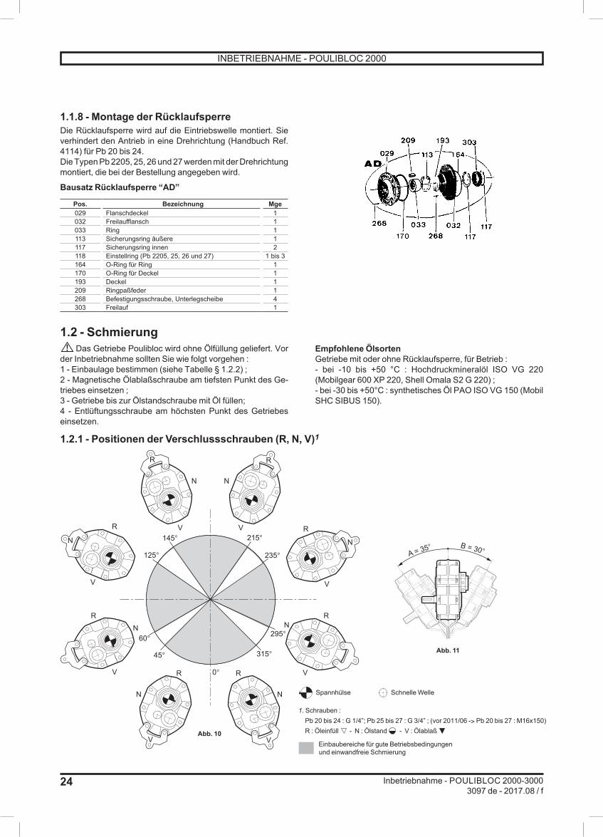
1.1.8 - Montage der RücklaufsperreDie Rücklaufsperre wird auf die Eintriebswelle montiert. Sie verhindert den Antrieb in eine Drehrichtung (Handbuch Ref. 4114) für Pb 20 bis 24.Die Typen Pb 2205, 25, 26 und 27 werden mit der Drehrichtung montiert, die bei der Bestellung angegeben wird.
Bausatz Rücklaufsperre “AD”
Pos. Bezeichnung Mge029 Flanschdeckel 1032 Freilaufflansch 1033 Ring 1113 Sicherungsring äußere 1117 Sicherungsring innen 2118 Einstellring (Pb 2205, 25, 26 und 27) 1 bis 3164 O-Ring für Ring 1170 O-Ring für Deckel 1193 Deckel 1209 Ringpaßfeder 1268 Befestigungsschraube, Unterlegscheibe 4303 Freilauf 1
1.2 - SchmierungDas Getriebe Poulibloc wird ohne Ölfüllung geliefert. Vor
der Inbetriebnahme sollten Sie wie folgt vorgehen :1 - Einbaulage bestimmen (siehe Tabelle § 1.2.2) ;2 - Magnetische Ölablaßschraube am tiefsten Punkt des Ge-triebes einsetzen ;3 - Getriebe bis zur Ölstandschraube mit Öl füllen;4 - Entlüftungsschraube am höchsten Punkt des Getriebes einsetzen.
Empfohlene ÖlsortenGetriebe mit oder ohne Rücklaufsperre, für Betrieb :- bei -10 bis +50 °C : Hochdruckmineralöl ISO VG 220 (Mobilgear 600 XP 220, Shell Omala S2 G 220) ;- bei -30 bis +50°C : synthetisches Öl PAO ISO VG 150 (Mobil SHC SIBUS 150).
1.2.1 - Positionen der Verschlussschrauben (R, N, V)1
0°
45°
60°
125°
145°
N
N N
N N
N N
R
R R
R
R R
R R
N
V
V V
V
V V
V
V215°
235°
295°
315°
A = 35° B = 30°
Spannhülse
1. Schrauben :Pb 20 bis 24 : G 1/4”; Pb 25 bis 27 : G 3/4” ; (vor 2011/06 -> Pb 20 bis 27 : M16x150)R : Öleinfüll - N : Ölstand - V : Ölablaß
Einbaubereiche für gute Betriebsbedingungenund einwandfreie Schmierung
Schnelle Welle
Abb. 11
Abb. 10
INBETRIEBNAHME - POULIBLOC 2000

25
Inbetriebnahme - POULIBLOC 2000-30003097 de - 2017.08 / f
de
1.2.2 - Ölmenge ((je nach Einbaulage des Getriebes)1
Falls vorhanden, die Entlüftungsschraube am höchsten Punkt des Getriebes einsetzen
Einbaulage
Pb 20 Pb 21 Pb 22 Pb 23 Pb 24 Pb 25 Pb 26 Pb 27G 1/4” G 1/4” G 1/4” G 1/4” G 1/4” G 3/4” G 3/4” G 3/4”
Liter1 Liter1 Liter1 Liter1 Liter1 Liter1 Liter1 Liter1
B3
0,75 1 1,75 2,5 4 5 8,5 14
B60,75 0,9 1,75 2,3 3,55 5,2 8,3 13
B70,75 0,9 1,75 2,3 3,55 5,2 8,3 13
B8
0,7 0,75 1,4 2 3,3 4,9 7,6 12
V51,25 1,5 2,25 3,5 4,5 6,5 9,5 17
1. Toleranz : ± 0,05 Liter bei einer Ölmenge < 5 Liter± 2% bei einer Ölmenge ≥ 5 Liter
ÖlmengenDie angegebenen Ölmengen (siehe Tabelle) sind nur Richtwerte, sie sollten lediglich dazu dienen, den notwendigen Ölvorrat festzulegen. Zur Bestimmung der genauen Ölmenge muß das Getriebe bis zur Ölstandschraube mit Öl gefüllt werden (Abb. 10).
Anmerkung : Bei Schräglage der Getriebe abweichend von der Senkrechten kann die Ölstandschraube bei einer Schräglage bis A=35° und B=30° noch benutzt werden (Abb. 11).Bei Montage in einer speziellen, hier nicht aufgeführten Position, die Ölmenge bitte anfragen.
1.3 - Wartung- Mineralöl: Ölwechsel alle 5000 Betriebsstunden (oder alle 6 Monate).- Synthetisches Öl: Bei einer Betriebstemperatur bis 70 °C Ölwechsel alle 25000 Betriebsstunden. Es ist jedoch ratsam,
den Ölstand in regelmäßigen Abständen zu kontrollieren (alle 5000 Betriebsstunden). Öl nachfüllen, wenn der Stand niedrig ist.
INBETRIEBNAHME - POULIBLOC 2000

26
Inbetriebnahme - POULIBLOC 2000-30003097 de - 2017.08 / f
2 - POULIBLOC 30002.1 - Empfehlungen zu installationDie Installation muß von qualifiziertem Fachpersonal durchgeführt werden. Sehen Sie wegen der Zugänglichkeit der Verschraubungen ausreichend Platz um das Getriebe herum vor.Getriebe :Beachten Sie zu Aufstellung und Installation des Getriebes Poulibloc 3000 die Anweisungen der allgemeinen Inbetrieb-nahmeanleitung unter “Empfehlungen”.
2.1.1 - StempelungLeistungsschild des Getriebes :1 - Definition des Getriebes ;2 - Einbaulage ;3 - Befestigungsart (NU) ;4 - Untersetzung des Getriebes ;5 - Fabrikationsnummer ;6 - Spiel : Pb für 10.000 Betriebsstunden mit Fett geschmiert.
Ni min-1
MOTEURSLEROY-SOMER
5010
88
Pb 3105 B3 NU389 417 900 / 0035,08EP 0
1 5 2 34
6Pbh Geliefert ohne Öl.
Ni min-1
MOTEURSLEROY-SOMER
5010
88
Pbh 3208 B3 NU389 417 901 / 0017,85
1 5 2 34
62.1.2 - MontageDas Gerät direkt auf der Welle der anzutreibenden Maschine montieren und dann, im Falle der Pbh-Serie, axial mit den beiden dafür vorgesehenen Feststellschrauben oder mit Schrauben und Scheiben am Wellenende feststellen.Für eine leichtere Montage und spätere Demontage wird es dringend empfohlen, die Welle der Maschine und die Bohrung der Hohlwelle mit Molybdändisulfidfett einzustreichen.
Eine Passfeder benutzen.
2.2 - SchmierungPb 3000 :Für den Betrieb zwischen -20°C und +40°C wird das Getriebe Pb 3000 standardmäßig mit einem Fett geliefert (Mobil, MOBILUX EP 0).Pbh 3000 :Das Getriebe Pbh 3000 wird ohne Ölfüllung geliefert. Vor der Inbetriebnahme sollten Sie wie folgt vorgehen :1 - Magnetische Ölablaßschraube am tiefsten Punkt des Ge-triebes einsetzen ;2 - bis zu einem Drittel der Höhe mit Öl befüllen (Position B3) ;3 - Entlüftungsschraube am höchsten Punkt des Getriebes einsetzen.Empfohlene Ölsorten : für Betrieb bei -10 bis +50°C : Hochdruckmineralöl ISO VG 220 ; bei -30 bis +50°C : synthetisches Öl PAO ISO VG 150 (Mobil SHC SIBUS 150).
Für Anwendungen mit sehr niedrigen Drehzahlen wird das Gehäuse vollständig mit Öl befüllt, weil es keine Tauchschmierung gibt.Einlaufen: nach ungefähr 200 Betriebsstunden den ersten Ölwechsel durchführen.
Niemals ein Additiv benutzen oder Dotieren, wenn eine Rücklaufsperre installiert ist.
2.2.1 - Positionen der Verschlussschrauben1
4
2
3
2
2.2.2 - Ölmenge1
Falls vorhanden, die Entlüftungsschraube am höchsten Punkt des Getriebes einsetzen
Einbaulage Verschlusss-chraube n°
Pbh 31 Pbh 32 Pbh 33G 1/2” G 1/2” G 1/2”Liter1 Liter1 Liter1
B3 3
1 1,7 2,75431
B6 4
1 1,7 2,75433
B7 2
1 1,7 2,75343
B8 3
1 1,7 2,75144
V5 1
1 1,7 2,75211
1. Toleranz : ± 0,05 Liter bei einer Ölmenge < 5 Liter
Ölstand - Ölablaß - Entlüftung - Öleinfüll
2.3 - WartungDie Getriebe erfordern ein Mindestmaß an Instandhaltung und einige einfache Vorsichtsmaßnahmen bei einer eventuellen Demontage :- Mineralöl: Ölwechsel alle 5000 Betriebsstunden.- Synthetisches Öl: Bei einer Betriebstemperatur bis 70 °C Ölwechsel alle 25000 Betriebsstunden. Es ist jedoch ratsam, den Ölstand in regelmäßigen Abständen zu kontrollieren. Außerdem muss regelmäßig überprüft werden, ob die Hauptriemen im Betrieb nicht zu stark gespannt sind und der Antrieb korrekt fluchtet. Die Schmierungsvorschriften einhalten. Für eine Benutzung unter anomalen Temperatur-bedingungen wenden Sie sich bitte an uns, um Ihnen die angemessenen Ölmengen mitzuteilen.
Zuviel Öl führt zu anomaler Erwärmung und Lecks.
INBETRIEBNAHME - POULIBLOC 3000

POULIBLOC 2000-3000
Instalación
Reductor de montaje pendular
Referencia: 3097 es - 2017.08 / f
es

28
Instalación - POULIBLOC 2000-30003097 es - 2017.08 / f
Este documento es complemento del manual general ref. 2557 (recomendaciones),ref. 3711 (recomendaciones específicas ATEX) y del manual mantenimiento Poulibloc 2000-3000 ref. 5069.
NOTALEROY-SOMER se reserva el derecho de cambiar las características de sus productos en todo momento para incorporar los últimos desarrollos tecnológicos. La información que contiene este documento puede por tanto cambiar sin previo aviso.LEROY-SOMER no da ninguna garantía contractual, de ningún tipo, con respecto a la información contenida en este documento y no se responsabiliza de posibles errores que el mismo pueda contener ni de posibles daños que puedan resultar de su uso.
ATENCIÓNLas prescripciones, instrucciones y descripciones corresponden a la ejecución standard. Éstas no tienen en cuenta variantes constructivas o adaptaciones especiales. El incumplimiento de estas recomendaciones puede provocar un deterioro rematuro del reductor y la no aplicación de la garantía por parte del fabricante.
Este símbolo indica en el manual una advertencia acerca de las consecuencias de una utilización no adecuada del Poulibloc 2000-3000, riesgos que pueden ocasionar lesiones corporales o daños materiales.
A pesar de todas las precauciones to madas para fabricar y comprobar este material, LEROY-SOMER no puede garantizar de por vida la ausencia de fugas de lubricante. En caso de que leves pérdidas puedan acarrear consecuencias graves que perjudiquen laseguridad de bienes y personas, el instalador y el usuario deben tomar todas las precauciones necesarias para evitar dichas consecuencias.
SUMARIO
1 - POULIBLOC 2000 ................................................................................................................291.1 - Recomendaciones de instalación ................................................................................................................ 29
1.1.1 - Identificación ........................................................................................................................................ 291.1.2 - Montaje del anillo conico ...................................................................................................................... 291.1.3 - Montaje del reductor ............................................................................................................................ 301.1.4 - Montaje de la polea en el eje primario .................................................................................................. 301.1.5 - Montaje del brazo de reacción ............................................................................................................. 301.1.6 - Implantación del motor ......................................................................................................................... 301.1.7 - Montaje del eje hueco cilindrico con el eje de la maquina a accionar ................................................... 31
1.1.8 - Montaje del antirretorno ....................................................................................................................... 321.2 - Lubricación .................................................................................................................................................. 32
1.2.1 - Posiciones de los tapones .................................................................................................................... 32
1.2.2 - Cantidad de aceite ............................................................................................................................... 331.3 - Mantenimiento ............................................................................................................................................. 33
2 - POULIBLOC 3000 ................................................................................................................342.1 - Recomendaciones de instalación ................................................................................................................ 34
2.1.1 - Identificación ........................................................................................................................................ 34
2.1.2 - Montaje ................................................................................................................................................ 342.2 - Lubricación .................................................................................................................................................. 34
2.2.1 - Posiciones de los tapones .................................................................................................................... 34
2.2.2 - Cantidad de aceite ............................................................................................................................... 342.3 - Mantenimiento ............................................................................................................................................. 34
Copyright 2013 : MOTEURS LEROY-SOMER. Este documento pertenence a MOTEURS LEROY-SOMER. No puede ser reproducido en ninguna forma sin nuestra autorización previa. Marcas, modelos et patentes registrados.
INSTALACIÓN - POULIBLOC 2000-3000

29
Instalación - POULIBLOC 2000-30003097 es - 2017.08 / f
es
1 - POULIBLOC 20001.1 - Recomendaciones de instalaciónLa instalación debe ser realizada por personal cualificado.Hay que prever un espacio libre suficiente para el acceso a los tapones.
Para el reductor :Para instalar el reductor Poulibloc 2000, seguir las instruc-ciones de las notas generales “Recomendaciones”.
1.1.1 - IdentificaciónPlaca de características del reductor :1- tipo de reductor ;2- posición de funcionamiento ;3- tipo de fijación RK : brazo de reacción ;- posibles opciones (AD) ;4- reducción del reductor ;5- número de série ;6- lubricante : entregado sin aceite.
Ni min-1
MOTEURSLEROY-SOMER
5010
88
Pb 2212 B3 RK389 417 902 / 00312
1 5 2 34
6
1.1.2 - Montaje del anillo conicoAnillo con diámetro pequeño (fig. 1)- Montar la chaveta (1) en la ranura del anillo cónico (2).- Insertar el anillo cónico (2) en el eje hueco del reductor asegurándose de que la chaveta esté bien colocada en la ranura del moyú.- Enfrentar la rosca de la tuerca de bolas circulantes (3) en el anillo cónico y darle 2 vueltas en el sentido contrario a las agujas del reloj.
Anillo con diámetro grande (fig. 2)- Instalar la chaveta especial (4) en la ranura del eje hueco.- Insertar el anillo cónico (2) en el eje hueco del reductor.- Enfrentar la rosca de la tuerca de bolas circulantes (3) en el anillo cónico y darle 2 vueltas en el sentido contrario a las agujas del reloj.
1
2F
GA
H7GB
3
4
2
3
Ejes huecos standard (fig. 1) Anillos cónicos según tallaD H7 F GB GA 20 21 22 23 24 25 26 27
20 6 16,5 22,5 l
25 8 21 28 l l
30 8 26 33 l l l
35 10 30 38 ll l l l
40 12 35 43 ll l l l
45 14 39,5 48,5 ll l l l
50 14 44,5 53,5 ll ll l l
55 16 49 59 ll ll l
60 18 53 64 ll l l
65 18 58 69 l l
70 20 62,5 74,5 ll l l
75 20 67,5 79,5 ll l l
80 22 71 85 ll l
85 22 76 90 ll l
90 25 81 95 l l
95 25 86 100 ll
100 28 90 106 ll l
110 28 100 116 l
120 32 109 127 l
Longitud mínima del eje accionado80 82 105 116 134 153 194 260
l Chaveta cliente para pequeños ejes huecos, cotas GA indicadas.ll Chaveta suministrada, lados GA no indicados.
fig. 1 fig. 2
INSTALACIÓN - POULIBLOC 2000

30
Instalación - POULIBLOC 2000-30003097 es - 2017.08 / f
1.1.3 - Montaje del reductor (fig. 3)- Montar el reductor con su anillo en el eje a accionar (5).Nota: para los anillos de diámetro grande, procurar que se inserte bien chaveta especial en la ranura del moyú.- Deslizar el reductor hasta la posición deseada. Ha de ser montado de tal manera que la cota “A” sea como minimo de 6 mm y como máximo igual al diámetro del eje.- Apretar la tuerca de bolas circulantes (3) con la llave especial(suministrada) hasta que el anillo esté completamente colocado en el reductor. No aplicar un esfuerzo de apriete a la tuerca superior a 70 N.m.- Apretar el tornillo de bloqueo (6) de la tuerca.Nota : supervisar y apretar el anillo cónico después de 8 horas de funcionamiento.Para desmontar el reductor o el anillo cónico, efectuar las mismas operaciones en el orden contrario.
No retire nunca el tornillo marca 299 (tornillos de retención de bolas).
Nota : el tapón de protección del moyú puede ser retirado en caso de que el eje atraviese el reductor. En los otros casos, dejarlo en su lugar como protección contra el polvo y la intemperie.
1.1.4 - Montaje de la polea en el eje primarioRetirar el material de protección del eje primario y limpiar el eje con un disolvente si es necesario.
Montar la polea en el eje primario del reductor lo más cerca posible del tacón, si no un esfuerzo radial demasiado importante reduciria la duración de vida de las rodamientos (fig.4). Utilizar un mazo flexible (neopreno) o calentar la polea para facilitar el montaje.Cuidado : una tensión excesiva de las correas puede reducir considerablemente su duración de vida y dañar los rodamientos (motor, reductor). Seguir las instrucciones del fabricante de correas.Cerciorarse del paralelismo correcto de las poleas y correas.Cuidado : por razones de seguridad, es indispensable prever una cubierta protectora alrededor de la poleas y correas.
1.1.5 - Montaje del brazo de reacciónFijar los brazos de reacción al cárter del reductor. Se recomien-dan tres posiciones, aunque unas ocho sean posibles (fig. 6).Montar el brazo de reacción y fijar el estribo de anclaje a un soporte rigido.Todas las fuerzas pasan por el brazo de reacción, por ello su mejor posición es a 90° de la línea que pasapor su agujero de fijación y el eje hueco del reductor (fig. 7, 8 & 9).El brazo de reacción ha de estar siempre montado de manera a que la fuerza de reacción esté en tracción en el reductor. La zona de fijación, que depende del sentido de rotación del eje lento, será :- zona A para rotación de sentida horario (fig. 5a).- zona B para rotación de sentido contrario a las agujas del reloj (fig. 5b).
1.1.6 - Implantación del motorLa tensión de la correa es ajustada por el brazo de reacción.Instalar el motor de tal manera que la correa forme un ángulo de 90° con la línea que pasa por los ejes de entrada y de salida del reductor.
No embridar el cárter del Poulibloc en el armazón de la máquina, utilizar la cartela de reacción.
Zona A : sentida de rotación horario Zona B : sentida de rotación contrario a las agujas del reloj
fig. 3
fig. 4
fig. 6fig. 7 fig. 8 fig. 9
fig. 5bfig. 5a
Poulibloc visto dellado del anillo cónico
INSTALACIÓN - POULIBLOC 2000

31
Instalación - POULIBLOC 2000-30003097 es - 2017.08 / f
es
1.1.7 - Montaje del eje hueco cilindrico con el eje de la maquina a accionar
Tallas ØA B CMoyú
CEje
Eje clienteLongitud
min.Longitud
máx.Pb 20 38 10 41,3 41 75 90
Pb 2142 12 45,3 45 75 10045 14 48,8 48,5 75 100
Pb 22
48 14 51,8 51,5 95 11050 14 53,8 53,5 95 11055 16 59,3 59 95 11060 18 64,4 64 95 110
Pb 2355 16 59,3 59 105 12060 18 64,4 64 105 120
Pb 2465 18 69,4 69 125 14570 20 74,9 74,5 125 14575 20 79,9 79,5 125 145
Pb 2575 20 79,9 79,5 150 18580 22 85,4 85 150 18585 22 90,4 90 150 185
Pb 2680 22 85,4 85 190 220
100 28 106,4 106 190 220
Pb 27
90 25 95,4 95 260 310100 28 106,4 106 260 310105 28 111,4 111 260 310110 28 116,4 116 260 310120 32 127,4 127 260 310
B
A
C
1 - Comprobar que el eje cilíndrico esté mecanizado según la norma NF - E 22 - 175, con un ajuste corredizo : g6, (el moyú es : H7).2 - Comprobar que la chaveta esté normalizada y que el eje tenga longitud mínima : ver tabla § 1.1.2.3 - Antes del montaje, desengrasar todas las piezas, procu-rando no echar disolvente sobre las juntas.Lubricar ligeramente las piezas en contacto a fin de evitar la corrosión. El montaje debe ser efectuado sin golpes según el procedimiento siguiente.El reductor Pb 27 se monta sobre el eje de la máquina con la ayuda de un esparrago roscado, atornillado en el eje.Enroscando la tuerca que se apoya en la arandela, se introduce el eje en el moyú cilíndrico del Poulibloc sin golpes.
MONTAJEPb 20-- a Pb 26--
Pb 27--
Fijación en eje con tacón
Fijación sobre eje liso
DESMONTAJEPb 20-- a Pb 26--
Pb 27--
El desmontaje se realiza utilizando un extractor hidráulico apoyado en la garganta exterior del moyú.
Junta tórica
Junta tórica
Junta tórica
Junta tórica
INSTALACIÓN - POULIBLOC 2000

32
Instalación - POULIBLOC 2000-30003097 es - 2017.08 / f
1.1.8 - Montaje del antirretornoEl antirretorno, utilizado para impedir la rotación del reductor en un sentido, se monta sobre el eje primario (manual ref. 4114) para Pb 20 a 24.Para los tipos Pb 2205, 25, 26 y 27, está instalado con el sentido de rotación precisado en el pedido.
Kit pour ADRef. Denominación Cant.029 tapa de brida 1032 brida de rueda libre 1033 anillo 1113 circlips exterior 1117 circlips interior 2118 cala de ajuste (Pb 2205, 25, 26 y 27) 1 a 3164 junta tórica de anillo 1170 junta tórica de tapa 1193 tapón de brida 1209 chaveta de anillo 1268 tornillo de fijación, tuercas 4303 rueda libre 1
1.2 - LubricaciónEl reductor Poulibloc se entrega sin aceite. Antes de ser
puesto en servicio, hay que :1 - determinar la posición de montaje (ver tabla § 1.2.2) ;2 - instalar el tapón de vaciado (magnético) en el punto bajo del reductor ;3 - llenar de aceite hasta el tapón de nivel ;4 - instalar el tapón respiradero en el punto más alto del reductor.
Aceites recomendadosReductor con o sin antirretorno, para funcionamiento :- entre -10 y +50°C : aceite mineral con presión extrema ISO VG 220 (Mobilgear 600 XP 220, Shell Omala S2 G 220) ;- entre -30 y +50°C : aceite sintético PAO ISO VG 150 (Mobil SHC SIBUS 150).
1.2.1 - Posiciones de los tapones (R, N, V)1
0°
45°
60°
125°
145°
N
N N
N N
N N
R
R R
R
R R
R R
N
V
V V
V
V V
V
V215°
235°
295°
315°
A = 35° B = 30°
Anillo cónico
1. Tapones :Pb 20 a 24 : G 1/4”; Pb 25 a 27 : G 3/4” ; (antes de 2011/06 -> Pb 20 a 27 : M16x150)R : llenado - N : nível - V : vaciado
Zonas de implantación para un buen functionamientodel mecanismo y una lubrificación perfecta
Eje rápido
fig. 11
fig. 10
INSTALACIÓN - POULIBLOC 2000

33
Instalación - POULIBLOC 2000-30003097 es - 2017.08 / f
es
1.2.2 - Cantidad de aceite (según posición de funcionamiento)1
Colocar el tapón respiradero en la parte superior del reductor
Posición defuncionamiento
Pb 20 Pb 21 Pb 22 Pb 23 Pb 24 Pb 25 Pb 26 Pb 27G 1/4” G 1/4” G 1/4” G 1/4” G 1/4” G 3/4” G 3/4” G 3/4”
litros1 litros1 litros1 litros1 litros1 litros1 litros1 litros1
B3
0,75 1 1,75 2,5 4 5 8,5 14
B60,75 0,9 1,75 2,3 3,55 5,2 8,3 13
B70,75 0,9 1,75 2,3 3,55 5,2 8,3 13
B8
0,7 0,75 1,4 2 3,3 4,9 7,6 12
V51,25 1,5 2,25 3,5 4,5 6,5 9,5 17
1. Tolerancia : ± 0,05 litro para cantidad de aceite < 5 litros ± 2% para cantidad de aceite ≥ 5 litros
Capacidad en aceiteLas cantidades de aceite indicadas (ver tabla) son aproxi-madas : sólo sirve para determinar el volumen de aceite a aprovisionar. Para la cantidad exacta, rellenar el reductor hasta su tapón de nivel (fig. 10).
Nota : para una inclinación con relación a la horizontal, los tapones de nivel pueden ser utilizados hasta A=35° y B=30° (fig. 11).Para un montaje en posición especial no indicada, consúltenos.
1.3 - Mantenimiento- Aceite mineral : vaciado cada 5000 horas (o cada 6 meses).- Aceite sintético : para una temperatura de funcionamiento hasta 70°C, cambio cada 25000 horas. Se recomienda verifi-
car periódicamente el nivel de aceite (cada 5000 horas) y añadir aceite si el nivel está bajo.
INSTALACIÓN - POULIBLOC 2000

34
Instalación - POULIBLOC 2000-30003097 es - 2017.08 / f
2 - POULIBLOC 30002.1 - Recomendaciones de instalaciónLa instalación debe ser realizada por personal cualificado.Hay que prever un espacio libre suficiente para el acceso a los tapones.Para el reductor :Para instalar el reductor Poulibloc 3000, seguir las instruc-ciones de las notas generales “Recomendaciones”.
2.1.1 - IdentificaciónPlaca de características del reductor :1- tipo de reductor ;2- posición de funcionamiento ;3- tipo de fijación (NU) ;4- reducción del reductor ;5- número de série ;6- lubricante : Pb lubricado con grasa para 10 000 horas de funcionamiento.
Ni min-1
MOTEURSLEROY-SOMER
5010
88
Pb 3105 B3 NU389 417 900 / 0035,08EP 0
1 5 2 34
6Pbh entregado sin aceite.
Ni min-1
MOTEURSLEROY-SOMER
5010
88
Pbh 3208 B3 NU389 417 901 / 0017,85
1 5 2 34
62.1.2 - MontajeConectar directamente el aparato al eje de la máquina a accionar, luego, en el caso de la serie Pbh, inmovilizarlo axialmente mediante dos tornillos puntiagudos previstos para ello, o mediante tornillos y arandelas en extremo del eje.Para facilitar el montaje, y un desmontaje ulterior, se aconseja recubrir el eje de la máquina y el mandrinado del eje hueco con grasa de bisulfuro de molibdeno.
Utilizar una clavija paralela.
2.2 - LubricaciónPb 3000 :Para un funcionamiento entre -20°C y +40°C, el reductor Pb 3000 es suministrado en estándar con una grasa (Mobil, MOBILUX EP 0).Pbh 3000 :El reductor Pbh 3000 se entrega sin aceite. Antes de ser puesto en servicio, hay que :1 - instalar el tapón de vaciado (magnético) en el punto bajo del reductor ;2 - rellenar de aceite al tercio de la altura (posición B3) ;3 - instalar el tapón respiradero en el punto más alto del reductor.Aceites recomendados : para funcionamiento entre -10 y +50°C : aceite mineral con presión extrema ISO VG 220 ; entre -30 y +50°C : aceite sintético PAO ISO VG 150 (Mobil SHC SIBUS 150).
Para las aplicaciones a muy baja velocidad, el cárter se rellenará completamente de aceite debido al barboteo inexistente.Rodaje: después de aproximadamente 200 horas, efectuar un primer vaciado.
Nunca utilizar aditivo o dopado si está instalado un antiderivador.
2.2.1 - Posiciones de los tapones1
4
2
3
2
2.2.2 - Cantidad de aceite1
Colocar el tapón respiradero en la parte superior del reductor
Posición defuncionamiento
Tipo detapones n°
Pbh 31 Pbh 32 Pbh 33G 1/2” G 1/2” G 1/2”litros1 litros1 litros1
B3 3
1 1,7 2,75431
B6 4
1 1,7 2,75433
B7 2
1 1,7 2,75343
B8 3
1 1,7 2,75144
V5 1
1 1,7 2,75211
1. Tolerancia : ± 0,05 litro para cantidad de aceite < 5 litros
Nível - Vaciado - Respiradero - Llenado
2.3 - MantenimientoLos reductores requieren un mínimo de mantenimiento y, durante un desmontaje eventual, ciertas precauciones elementales :- aceite mineral : vaciado cada 5000 horas.- aceite sintético : para una temperatura de funcionamiento hasta 70°C, cambio cada 25000 horas. Se recomienda verificar periódicamente el nivel de aceite. Igualmente es importante verificar periódicamente que la tensión en funcionamiento de las correas primarias no es exagerada y que el alineamiento de la transmisión es correcto. Observas las prescripciones de lubricación.Para una utilización en condiciones anormales de temperatura, consultarnos para obtener las cantidades de aceite convenientes.
Un exceso de aceite provoca un calentamiento anormal y fugas.
INSTALACIÓN - POULIBLOC 3000


Moteurs Leroy-SomerHeadquarter: Boulevard Marcellin Leroy - CS 10015
16915 ANGOULÊME Cedex 9
Limited company with capital of 65,800,512 €RCS Angoulême 338 567 258
www.leroy-somer.com