lesson 9 - ctqp home page shaft inspector/09 - 2015... · student’s guide lesson 9- post...
TRANSCRIPT

Student’s Guide Lesson 9- Post Installation
Version 1 -1/15 9-1
9-1
Lesson 9
POST INSTALLATION

Student’s Guide Lesson 9- Post Installation
Version 1 -1/15 9-2
9-2
• Identify and describe various Integrity and Load Tests
• Construction tolerances
• Describe the Drilled Shaft Pay Items
• Identify the applicable 455 specifications
Learning Outcomes

Student’s Guide Lesson 9- Post Installation
Version 1 -1/15 9-3
9-3
Checklist

Student’s Guide Lesson 9- Post Installation
Version 1 -1/15 9-4
9-4
455-20 Construction Tolerances.
Meet the following construction tolerances for drilledshafts:
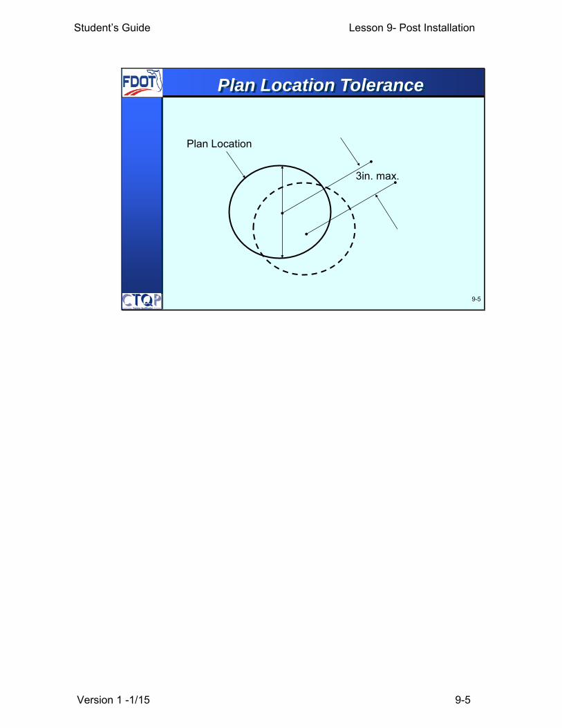
(a) Ensure that the top of the drilled shaft is no more than 3inches laterally in the X or Y coordinate from the positionindicated in the plans.(b) Ensure that the vertical alignment of the shaftexcavation does not vary from the alignment shown in theplans by more than 1/4 in/ft of depth.(c) After placing all the concrete, ensure that the top of thereinforcing steel cage is no more than 6 inches above andno more than 3 inches below plan position.
455-20- Construction Tolerances
Student’s Guide Lesson 9- Post Installation
Version 1 -1/15 9-5
9-5
Plan Location Tolerance
3in. max.
Plan Location
Student’s Guide Lesson 9- Post Installation
Version 1 -1/15 9-6
9-6
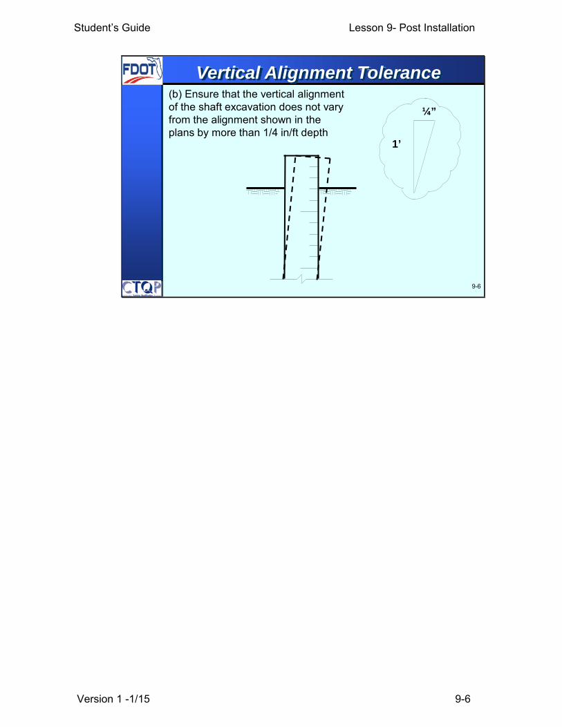
¼”
1’
Vertical Alignment Tolerance (b) Ensure that the vertical alignment of the shaft excavation does not vary from the alignment shown in the plans by more than 1/4 in/ft depth

Student’s Guide Lesson 9- Post Installation
Version 1 -1/15 9-7
9-7
Reinforcement Cage Tolerance
Rebar CagePlanElevation
6”
3”
(c) After placing all the concrete, ensure that the top of the reinforcing steel cage is no more than 6 inches above and no more than 3 inches below plan position.
Student’s Guide Lesson 9- Post Installation
Version 1 -1/15 9-8
9-8
455-20- Construction Tolerances
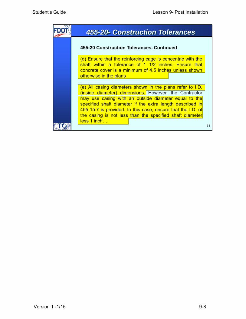
455-20 Construction Tolerances. Continued
(d) Ensure that the reinforcing cage is concentric with theshaft within a tolerance of 1 1/2 inches. Ensure thatconcrete cover is a minimum of 4.5 inches unless shownotherwise in the plans.(e) All casing diameters shown in the plans refer to I.D.(inside diameter) dimensions. However, the Contractormay use casing with an outside diameter equal to thespecified shaft diameter if the extra length described in455-15.7 is provided. In this case, ensure that the I.D. ofthe casing is not less than the specified shaft diameterless 1 inch….

Student’s Guide Lesson 9- Post Installation
Version 1 -1/15 9-9
9-9
1 ½” ConcentricallyMinimum 4.5”
Concrete Cover
Construction Tolerances
ShaftReinforcementCage

Student’s Guide Lesson 9- Post Installation
Version 1 -1/15 9-10
9-10
455-20- Construction Tolerances
455-20 Construction Tolerances. Continued
e.) ….. When approved, the Contractor may elect toprovide a casing larger in diameter than shown in theplans to facilitate meeting this requirement. When casingis not used, ensure that the minimum diameter of thedrilled shaft is 1 inch less than the specified shaftdiameter. When conditions are such that a series oftelescoping casings are used, provide the casing sized tomaintain the minimum shaft diameters listed above.

Student’s Guide Lesson 9- Post Installation
Version 1 -1/15 9-11
9-11
455-20 Construction Tolerances. Continued
(f) Ensure that the top elevation of the drilled shaftconcrete has a tolerance of +1 and -3 inches from thetop of shaft elevation shown in the plans.
455-20- Construction Tolerances

Student’s Guide Lesson 9- Post Installation
Version 1 -1/15 9-12
9-12
PlanTop-of-ShaftElevation
1”
3”
Top of Shaft Elevation Tolerance
Top of Concrete
Student’s Guide Lesson 9- Post Installation
Version 1 -1/15 9-13
9-13
455-20 Construction Tolerances. Continued
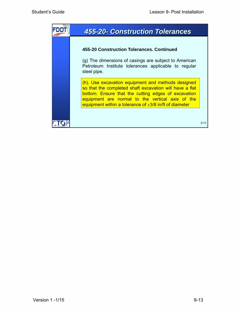
(g) The dimensions of casings are subject to AmericanPetroleum Institute tolerances applicable to regularsteel pipe.
(h). Use excavation equipment and methods designedso that the completed shaft excavation will have a flatbottom. Ensure that the cutting edges of excavationequipment are normal to the vertical axis of theequipment within a tolerance of ±3/8 in/ft of diameter
455-20- Construction Tolerances
Student’s Guide Lesson 9- Post Installation
Version 1 -1/15 9-14
455-21 Drilled Shaft Excavations Constructed out ofTolerance.Do not construct drilled shaft excavations in such amanner that the concrete shaft cannot be completedwithin the required tolerances. The Contractor may makecorrections to an unacceptable drilled shaft excavationby any combination of the following methods:(a) Overdrilling the shaft excavation to a larger diameterto permit accurate placement of the reinforcing steelcage with the required minimum concrete cover.(b) Increasing the number and/or size of the steelreinforcement bars.
9-14
455-21- …. Constructed out of Tolerance

Student’s Guide Lesson 9- Post Installation
Version 1 -1/15 9-15
9-15
455-21 Drilled Shaft Excavations Constructed out ofTolerance. Continued
…. When the tolerances are not met, the Contractormay propose a redesign to incorporate shafts installedout of tolerance into caps or footings. Incorporate shaftsinstalled out of tolerance at no expense to theDepartment. Ensure the Contractor’s Engineer ofRecord performs any redesign and signs and seals theredesign drawings and computations. Do not begin anyproposed construction until the redesign has beenreviewed for acceptability and approved by theEngineer….
455-21- …. Constructed out of Tolerance

Student’s Guide Lesson 9- Post Installation
Version 1 -1/15 9-16
9-16
455-21 Drilled Shaft Excavations Constructed out ofTolerance. Continued
…. Backfill any out of tolerance shafts in an approvedmanner when directed by the Engineer until theredesign is complete and approved. Furnish additionalmaterials and work necessary, including engineeringanalysis and redesign, to effect corrections of out oftolerance drilled shaft excavations at no expense to theDepartment.
455-21- …. Constructed out of Tolerance

Student’s Guide Lesson 9- Post Installation
Version 1 -1/15 9-17
9-17
What is the shaft plan location tolerance?
What is the tolerance for the rebar cage?
Learning Outcome

Student’s Guide Lesson 9- Post Installation
Version 1 -1/15 9-18
9-18
Post-Installation Testing
Statnamic AxialLoad Test
After a shaft is constructed the Engineer may require to perform some testing to verify integrity. Also some shafts may have been designated in the plans for load testing. We will now review Post-Installation testing. These may be integrity testing or lad testing.
the Inspector will not be performing the test, but should document which shaft, the setup in general, the time started and completed, if possible.
Student’s Guide Lesson 9- Post Installation
Version 1 -1/15 9-19
9-19
INTEGRITY TESTS
To evaluate the soundness or “integrity” ofthe constructed shaft.
LOAD TESTS
To determine if the shaft, as constructed, will carrythe loads designed for.
Post-Installation Testing
There are two types of post installation testing: Load test: The shafts were designed to carry a specified load and “load tests” are the test flights of drilled shafts. A specific number of shafts may be designated to be load tested. Integrity Testing The vast majority of drilled shafts are constructed routinely, without difficulty, and are sound structural elements. Occasionally, defects in the completed shaft can be introduced during the construction process through errors in handling of slurry, concrete, casings, cages and other factors. Therefore, tests to evaluate the soundness or integrity of the shaft are conducted. These become even more critical when difficult drilling and installation problems were encountered. These tests may include a variety of down-hole access tube tests, including Cross-hole Sonic Logging, thermal integrity testing and the inexpensive Sonic Echo test. The goal of these integrity tests are to determine if defects, or anomalies, exist within the constructed shaft.
Student’s Guide Lesson 9- Post Installation
Version 1 -1/15 9-20
9-20
Typically there are three types of Load testsconducted on drilled shafts:
• Axial (downward) ASTM D 1143
• Lateral (sideways) ASTM D 3966
• Uplift (upwards) ASTM 3689
Load Tests

Student’s Guide Lesson 9- Post Installation
Version 1 -1/15 9-21
9-21
455-2- Static Compression Load Test
455-2.1 General: Employ a professional testinglaboratory, or Specialty Engineer with prior load testexperience on at least three projects, to conduct the loadtest in compliance with these Specifications, to record alldata, and to furnish reports of the test results to theEngineer except when the Contract Documents showthat the Department will supply a Geotechnical Engineerto provide these services.
Perform the load test by applying a load up to the loadrequired in the Contract Documents or to the failure load,whichever occurs first….
Student’s Guide Lesson 9- Post Installation
Version 1 -1/15 9-22
9-22
455-2.1 General: Continued
…. Do not apply test loads to piles sooner than 48 hours(or the time interval shown in the plans) after driving ofthe test pile or reaction piles, whichever occurs last.
Allow up to four weeks after the last load test for theanalysis of the load test data and to provide all theestimated production tip elevations….
Do not begin static load testing of drilled shafts until theconcrete has attained a compressive strength of 3,400psi. The Contractor may use high early strength concreteto obtain this strength at an earlier time to preventtesting delays.
455-2- Static Compression Load Test

Student’s Guide Lesson 9- Post Installation
Version 1 -1/15 9-23
455-2.10 Disposition of Tested Piles/Shafts: Aftercompleting testing, cut off the tested piles/shafts, whichare not to be incorporated into the final structure, andany reaction piles/shafts at an elevation 24 inchesbelow the finished ground surface. Take ownership ofthe cut-offs and provide areas for their disposal.
9-23
455-2- Static Compression Load Test

Student’s Guide Lesson 9- Post Installation
Version 1 -1/15 9-24
9-24
• Conventional Methods (Reaction Frame and Reaction Shafts)
• Osterberg Load Cell(s)
• Statnamic Loading Device
Axial Load Tests

Student’s Guide Lesson 9- Post Installation
Version 1 -1/15 9-25
9-25Test Shaft
Reaction Frame
Anchor Shaft
Conventional- Reaction Frame and Shafts
This slide show the co nfiguration of a conve ntional load test. In a conventional test, we install reaction or anchor shafts on either side of the test shaft ; two or four can be used. T he reaction shafts sho uld be designed to have enough uplift capacity to serve as r eaction and not fail under the maximum compression load t hat will be applied to the test shaft during the load test. The anchor shafts should normally be constructed first. Hydraulic jacks are placed on top of the test shaft, usually on a steel plate that is carefully leveled. Electronic load cells are also freq uently placed above or below the jacks in order to obtain an accurate measure of th e load. A reaction frame spans the anchor shafts, as shown. Potential disadvantages of this method are that it is expensive compared to the other methods (perhaps twice as expensive, excluding the cost of the test shaft) and the capacity is limited because of the reaction frame. The conventional method can also be used to conduct uplift, or “pullout” test.

Student’s Guide Lesson 9- Post Installation
Version 1 -1/15 9-26
9-26
Conventional- Axial

Student’s Guide Lesson 9- Post Installation
Version 1 -1/15 9-27
9-27
Conventional- Lateral
This photo shows a lateral load test being conducted on a drilled shaft in the water. The test shaft is pushed away from the reaction shafts, not pulled toward them. The load is applied as a shear at the ground level and is measured with an electronic load cell. Both the lateral deflections at the level of the applied load and the slope of the shaft, at the head and along the shaft, are measured.
Student’s Guide Lesson 9- Post Installation
Version 1 -1/15 9-28
9-28
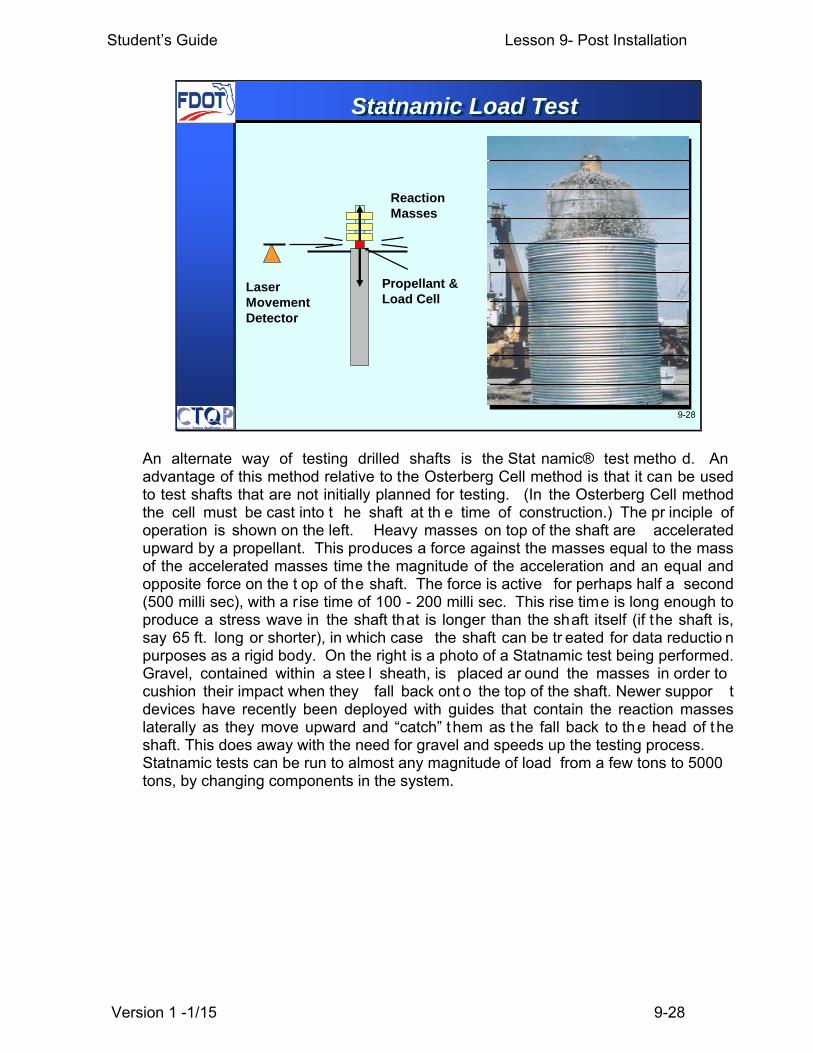
Reaction Masses
Propellant & Load Cell
Laser Movement Detector
Statnamic Load Test
An alternate way of testing drilled shafts is the Stat namic® test metho d. An advantage of this method relative to the Osterberg Cell method is that it can be used to test shafts that are not initially planned for testing. (In the Osterberg Cell method the cell must be cast into t he shaft at th e time of construction.) The pr inciple of operation is shown on the left. Heavy masses on top of the shaft are accelerated upward by a propellant. This produces a force against the masses equal to the mass of the accelerated masses time the magnitude of the acceleration and an equal and opposite force on the t op of the shaft. The force is active for perhaps half a second (500 milli sec), with a rise time of 100 - 200 milli sec. This rise time is long enough to produce a stress wave in the shaft that is longer than the shaft itself (if the shaft is, say 65 ft. long or shorter), in which case the shaft can be tr eated for data reductio n purposes as a rigid body. On the right is a photo of a Statnamic test being performed. Gravel, contained within a stee l sheath, is placed ar ound the masses in order to cushion their impact when they fall back ont o the top of the shaft. Newer suppor t devices have recently been deployed with guides that contain the reaction masses laterally as they move upward and “catch” them as the fall back to the head of the shaft. This does away with the need for gravel and speeds up the testing process. Statnamic tests can be run to almost any magnitude of load from a few tons to 5000 tons, by changing components in the system.
Student’s Guide Lesson 9- Post Installation
Version 1 -1/15 9-29
9-29
Statnamic Load Test
Student’s Guide Lesson 9- Post Installation
Version 1 -1/15 9-30
9-30
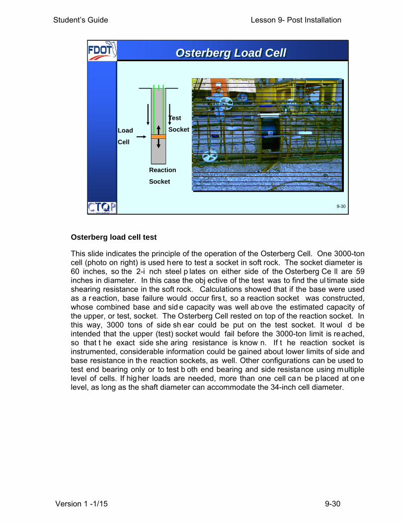
Load
Cell
Reaction
Socket
Test
Socket
Osterberg Load Cell
Osterberg load cell test
This slide indicates the principle of the operation of the Osterberg Cell. One 3000-ton cell (photo on right) is used here to test a socket in soft rock. The socket diameter is 60 inches, so the 2-i nch steel p lates on either side of the Osterberg Ce ll are 59 inches in diameter. In this case the obj ective of the test was to find the ul timate side shearing resistance in the soft rock. Calculations showed that if the base were used as a r eaction, base failure would occur firs t, so a reaction socket was constructed, whose combined base and sid e capacity was well ab ove the estimated capacity of the upper, or test, socket. The Osterberg Cell rested on top of the reaction socket. In this way, 3000 tons of side sh ear could be put on the test socket. It woul d be intended that the upper (test) socket would fail before the 3000-ton limit is reached, so that t he exact side she aring resistance is know n. If t he reaction socket is instrumented, considerable information could be gained about lower limits of side and base resistance in the reaction sockets, as well. Other configurations can be used to test end bearing only or to test b oth end bearing and side resistance using multiple level of cells. If higher loads are needed, more than one cell can be p laced at one level, as long as the shaft diameter can accommodate the 34-inch cell diameter.
Student’s Guide Lesson 9- Post Installation
Version 1 -1/15 9-31
9-31
• Cross-hole Sonic Logging (“CSL”)
• Thermal Integrity Profiling (TIP)
• Sonic Echo / Impulse-response (PIT)
• Coring
• Others
Integrity Tests
Student’s Guide Lesson 9- Post Installation
Version 1 -1/15 9-32
9-32
“Anomalies.” unusual patterns: voids or softspots in the concrete.
Anomalies maybe probable structural defectsif they correlate to some potentially damagingoccurrence during construction recorded bythe Inspector.
Anomolies
Various post-construction structural integrity tests can give “fal se positives” or divergences of a sonic or ionizing radiation record from that which would be expected from a structurally perfect drilled shaft. This does not always mean that t he shaft is defective. We m erely use t he term “anomaly” to denote any deviation from the “expected” in the integrity test record. If t hat deviation corresponds to a pot entially damaging event during construction, then it is prudent to assume that the anomaly is a structural defect that requires further attention. Note that good inspection records are key to the interpretation of integrity tests.

Student’s Guide Lesson 9- Post Installation
Version 1 -1/15 9-33
9-33
455-17.6.1 Cross-Hole Sonic Logging (CSL)Tests: Perform all CSL testing in accordance withASTM D 6760. Test all drilled shafts in bridgebents or piers considered nonredundant in theplans, using CSL. For all other drilled shafts,perform CSL testing only on drilled shafts selectedby the Engineer. The minimum number of shaftstested is the number of shafts indicated in theplans. The Engineer may increase the numbershafts tested as deemed necessary….
455-17.6- NDT of Drilled Shaft Integrity
Student’s Guide Lesson 9- Post Installation
Version 1 -1/15 9-34
455-17.6.1 Cross-Hole Sonic Logging (CSL) Tests:Continued
…. Engage a qualified Specialty Engineer to perform theCSL testing. The qualified CSL Specialty Engineer musthave a minimum three years experience of CSL testingand have a Florida Licensed Professional Engineersupervising the collection and interpretation of data. TheContractor shall provide all necessary assistance to theCSL Specialty Engineer to satisfactorily perform thetesting….
9-34
455-17.6- NDT of Drilled Shaft Integrity

Student’s Guide Lesson 9- Post Installation
Version 1 -1/15 9-35
9-35
CSL Access Tubes
CSL access tubes Several access tubes are placed regularly around the circumference of the cage. Our specification requires one per foot of shaft diameter. CSL Access tubes need to be cast into the concrete at the time of construction, which is the major disadvantage of tests employing access tubes. These tubes need to be straight and watertight their full length. Remember that as th e Inspector you must check to ensure the proper number of access tubes are posi tioned and that they are securely fastened and filled with water as specified.. You must also verify that the contractor personnel checks the tubes by inserting mock probes to make sure the tubes are not obstructed and will allow the performance of the tes ting. Failure to do so ma y result in a strike on the inspector’s record.

Student’s Guide Lesson 9- Post Installation
Version 1 -1/15 9-36
Cross-hole Sonic Logging
CSL testing
9-36
The left picture shows the probes used in the CSL test. The transmitter or vibration source, which is the black one, and the receiver which is the red one shown in the picture. The picture at the right illustrates the tubes being filled with water. It is important that this is performed previous to placing concrete as we saw in the previous lesson. The CSL tests is performed by testing one pair of tubes at a time. In one tube the vibration source or transmitter probe, is inserted and a receiver is inserted into the second tube. In the standard way of testing the two probes will be inserted to the bottom of the tubes and will be pulled up simultaneously at the same speed while measuring data. During the CSL measurements, the apparent signal travel time between transmitter and receiver are measured and recorded. By measuring the travel times of a pulse along a known distance, between transmitter and receiver, the velocity can be calculated as a function of distance over time. If a number of such measurements are made and compared at different points along the concrete structure, the overall integrity of the concrete can be assessed.

Student’s Guide Lesson 9- Post Installation
Version 1 -1/15 9-37
Cross-hole Sonic Logging
CSL testing
CSL method and various kinds of defects- anomalies ((a) Olsen Engineering, Inc. and (b) Stain, R.T., 1982)
9-37
This slide shows at t he left side a CSL t est being performed. Th e right sketch illustrates the test and the pri nciples used by the test. Defects in the concrete wil l delay the arrival t ime at the receiver probe. The arrival time will be longer than the time in a sound concrete and the wave speed will be less. Several variations on this method are practiced by highly skilled specialists, involving placing source and receiver at different elevations to develop a three-dimensional profile of the interior of the shaft, in a process referred to as tomography.

Student’s Guide Lesson 9- Post Installation
Version 1 -1/15 9-38
455-17.6.1 Cross-Hole Sonic Logging (CSL) Tests:Continued
…. When a shaft contains four tubes, test every possibletube combination. For shafts with five or more tubes, testall pairs of adjacent tubes around the perimeter, andonehalf of the remaining number of tube combinations, aschosen by the Engineer.
After acceptance of production shafts by the Engineer,remove all water from the access tubes or core holes andfill the tubes or core holes with a structural non-shrinkgrout approved by the Engineer….
9-38
455-17.6- NDT of Drilled Shaft Integrity
Student’s Guide Lesson 9- Post Installation
Version 1 -1/15 9-39
455-17.6.1.2 Procedure: Perform Cross-hole soniclogging between 72 hours and 25 calendar days of shaftconcrete placement and after the concrete compressivestrength exceeds 3,000 psi. Furnish informationregarding the shaft, tube lengths and depths,construction dates, and other pertinent shaft installationobservations and details to the Department at the time oftesting. Verify access tube lengths and their condition inthe presence of the Department, at least 24 hours priorto CSL testing. If the access tubes do not provide accessover the full length of the shaft, repair the existingtube(s) or core additional hole(s), as directed by theEngineer, at no additional cost to the Department.
9-39
455-17.6- NDT of Drilled Shaft Integrity
Student’s Guide Lesson 9- Post Installation
Version 1 -1/15 9-40
9-40
455-17.6- NDT of Drilled Shaft Integrity
Report any anomalies indicated by longer pulse arrivaltimes and significantly lower amplitude/energy signals tothe Engineer and conduct further tests as required toevaluate the extent of possible defects. Conduct offsetCSL measurements between all tube pair combinations inany drilled shafts with 30% or greater in velocity reduction.Record offset measurements with source and receiververtically offset in the tubes. These measurements addfour measurements per tube combination to the horizontalmeasurements described in this section. Offsetmeasurements are described by the angle (in degrees)and direction the signal travels between the probes withrespect to the horizontal plane: +45, +22.5 (source belowreceiver), and -45, -22.5 (source above receiver). Recordoffset measurements from the point
When the CSL shows wave speed reductions greater than 30% the contractor needs to provide additional field readings to perform tomography analysis.

Student’s Guide Lesson 9- Post Installation
Version 1 -1/15 9-41
9-41
455-17.6- NDT of Drilled Shaft Integrity
where the higher probe is at least 5 feet below thevelocity reduction to the point where the lower probe is atleast 5 feet above the velocity reduction. Provide offsetCSL logs and 3-D tomographic analysis of all CSL dataat no additional cost to the Department in the event 30%or greater in velocity reductions are detected.

Student’s Guide Lesson 9- Post Installation
Version 1 -1/15 9-42
9-42
Thermal Integrity Testing
Thermal Integrity Testing
This slide shows the equipment used for the Thermal Integrity testing. The test is also known as the Thermal Integrity Profiling. This is a relatively new integrity test method that takes advantage of the temperatures that are generated during cement hydration. The internal temperature of the shaft will be function of the amount of cementitious materials present in the shaft. In the same shaft, areas with low cement will be cooler than areas high cement. The test can use the same access tubes used for CSL testing or can use temperature sensors attached to the reinforcement. During the test a probe measures the internal temperature of the shaft at several points throughout the shaft. This test has the advantage over the CSL testing in that it can give information of the integrity of the shaft outside the CSL tubes. The disadvantage of this method is that it cannot be performed after few days because it requires the concrete to be hot. It is typically performed between 1 and 2 days after pouring of the concrete.
Student’s Guide Lesson 9- Post Installation
Version 1 -1/15 9-43
9-43
Thermal Integrity Testing
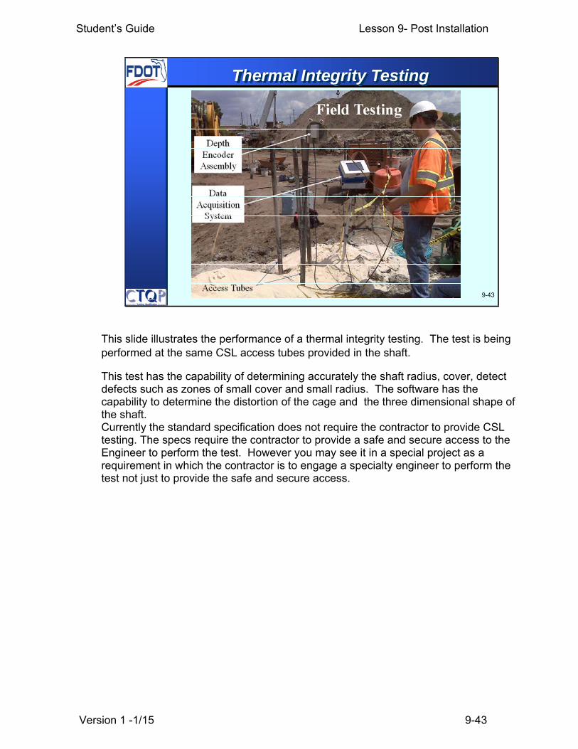
This slide illustrates the performance of a thermal integrity testing. The test is being performed at the same CSL access tubes provided in the shaft.
This test has the capability of determining accurately the shaft radius, cover, detect defects such as zones of small cover and small radius. The software has the capability to determine the distortion of the cage and the three dimensional shape of the shaft. Currently the standard specification does not require the contractor to provide CSL testing. The specs require the contractor to provide a safe and secure access to the Engineer to perform the test. However you may see it in a special project as a requirement in which the contractor is to engage a specialty engineer to perform the test not just to provide the safe and secure access.

Student’s Guide Lesson 9- Post Installation
Version 1 -1/15 9-44
9-44
Thermal Integrity Testing
455-17.6.2 Access for Thermal Integrity Testing: Provide safe and secure access and assistance to the Engineer, when requested, for the purpose of evaluating drilled shaft integrity via internal temperature measurements using the Thermal Integrity Test Method as described herein. ……
Student’s Guide Lesson 9- Post Installation
Version 1 -1/15 9-45
9-45
Thermal Integrity Testing
…Provide access to the Engineer for testing the shafts within 4 hours of the peak temperature generation, which is expected to occur between 24 hours and 48 hours after shaft concrete placement. Provide access to the Engineer for testing all drilled shafts in bridge bents or piers considered non-redundant in the Plans. Based on the observations during drilled shaft construction, the Engineer may test one or all drilled shafts in bridge bents or piers considered redundant in the Plans. For drilled shaft foundations supporting miscellaneous structures, only drilled shafts selected by the Engineer will be tested.

Student’s Guide Lesson 9- Post Installation
Version 1 -1/15 9-46
9-46
Sonic Echo Test (Pile Integrity Testing)
Sonic Echo Test or Pile Integrity testing This is a p hoto of a sonic-echo test being performed. Note that the technician has embedded a nai l in t he top o f the shaft’s concrete so as to provide a sh arp sonic wave. This will help find small defects near the top of the shaft. To search for deeper defects, a larg er hammer with a hard cushion might be used t o produce a sonic compression wave of longer lengt h that will propagate deeper (but with less resolution) than the sharp wave. Advantages of th e test are t hat it can be done on virtually any shaft without prior planning (no access tubes need be placed in the shaft) and is quick and inexpensive. Disadvantages are th at it is pro ne to show ing false positives and to missin g fairly large voids or inclusions in the concrete. It is essentially 100 per cent accurate only if the void or inclusion covers about half of the cross-sectional area of the shaft and is reasonably thick (say 18 inches (0.5 m) or thicker) and the test is performed correctly. This test is not usu ally effective in locating deep defects (depth > 60 feet (20 m) and cannot detect contact problems between the concrete and the soil or rock that is of similar strength to th at of the co ncrete, as t he signal essentially “dissipates”. False positives in this method come from changes in cross-section that are not associated with an anomaly, from changes in concre te modulus, such as at the i nterface between concrete placed from tw o different trucks, from changes in the stiffness of the soil or rock surrounding the shaft, which also dissipate sonic energy, and from testing technique errors such as setting the sensor on weak or powdery concrete.

Student’s Guide Lesson 9- Post Installation
Version 1 -1/15 9-47
9-47
Core Barrel Bit
Coring
Coring Coring of drilled shafts can be used as an independent integrity test method, or it can be used to attempt to confirm the presence of defects that appear as anomalies on CSL testing or pulse-echo records. Coring is not fool-proof, however, as cores can bypass serious defects. So, coring is a way of potentially confirming that the shaft is defective but not that it is no t defective. For example a good core take n in the middle of the shaft does not necessarily mean that a shaft is good. After all the best concrete is expected to be in the middle of the shaft where t he tremie pipe or pu mping line was. The defects are more likely to appear towards the outside of the shaft than towards the inside. That is why sometimes when defects are suspected coring may be required to be performed outside the cage. Very careful coring is sometimes an eff ective way to investigate whether there is a soft base in the drilled shaft.
Student’s Guide Lesson 9- Post Installation
Version 1 -1/15 9-48
9-48
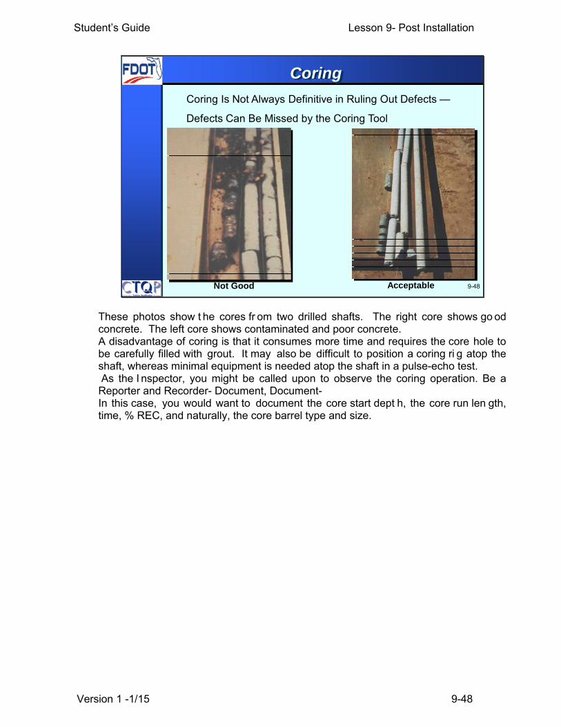
Coring Is Not Always Definitive in Ruling Out Defects —
Defects Can Be Missed by the Coring Tool
AcceptableNot Good
Coring
These photos show t he cores fr om two drilled shafts. The right core shows go od concrete. The left core shows contaminated and poor concrete. A disadvantage of coring is that it consumes more time and requires the core hole to be carefully filled with grout. It may also be difficult to position a coring ri g atop the shaft, whereas minimal equipment is needed atop the shaft in a pulse-echo test. As the I nspector, you might be called upon to observe the coring operation. Be a Reporter and Recorder- Document, Document- In this case, you would want to document the core start dept h, the core run len gth, time, % REC, and naturally, the core barrel type and size.

Student’s Guide Lesson 9- Post Installation
Version 1 -1/15 9-49
9-49
A Good Shaft
This is a 70-foot- long shaft constructed under mineral drilling slurry, load tested to geotechnical failure and then exhumed for observation. The shaft was almost perfectly cylindrical, and no concrete contamination could be observed.
A good shaft is more likely to occur when good construction practices, good specifications and inspection come together
Student’s Guide Lesson 9- Post Installation
Version 1 -1/15 9-50
9-50
All Pay Items should have been documented.
Pay Items
Pay Items We will cover in the final part of this lesson the drilled shaft pay items. Most contracts reimburse the Contractor per foot or meter of something, per each for some items and lump sum for a few th ings. These need to be recorded correctly. Depending upon their bid pr ice, the d ifference between 30 feet or 6 0 feet can represent a lot of dollars. Conversely, if the pay item should be 30 feet, not 60, FDOT doesn’t want to pay 60 feet. The Contractor is entitled to be paid for what was furnished, installed and accepted. We should make a comme nt regarding payment for miscellaneous structures foundations. Typically for miscellaneous structures the price of the drilled shaft is included within the price of the full installed structure. Therefore the pay items slides that we will cover will be applicable mostly for bridge foundations.

Student’s Guide Lesson 9- Post Installation
Version 1 -1/15 9-51
455-23.3 Unclassified Shaft Excavation: The quantity tobe paid for will be the length, in feet, of unclassified shaftexcavation of the diameter shown in the plans, completedand accepted, measured along the centerline of the shaftfrom the ground surface elevation after any requiredexcavation per 455-1.2 to the plan bottom of shaft elevationauthorized and accepted plus up to 15 feet or 3 shaftdiameters, whichever is deeper, of additional excavation asauthorized by the Engineer. When drilled shafts areconstructed through fills placed by the Contractor, theoriginal ground surface before the fill was placed will beused to determine the quantity of unclassified shaftexcavation. When the Contractor elects to use O.D. casing,the quantity as determined above will be multiplied by thefactor “F” determined as described in 455-23.1. 9-51
455-23- Method of Measurement
Student’s Guide Lesson 9- Post Installation
Version 1 -1/15 9-52
9-52
455-23- Method of Measurement
455-23.4 Unclassified Extra Depth Excavation: Whenexcavation is required by the Engineer to extend morethan 15 feet or 3 shaft diameters, whichever is deeper,below the bottom of the shaft elevation shown in theplans, the work will be considered as UnforeseeableWork.
455-23.5 Test Holes: The cost of all test holes will beincluded in the cost of Drilled Shafts.

Student’s Guide Lesson 9- Post Installation
Version 1 -1/15 9-53
455-23.6 Core (Shaft Excavation): The quantity to bepaid for will be the length, in feet, measured from thebottom of shaft elevation to the bottom of the core-hole, foreach authorized core drilled below the shaft excavation,completed and accepted. When the Engineer authorizespilot holes extending through part or all of the shaft, prior toexcavation, to some depth below the shaft bottom, thequantity paid as Core (Shaft Excavation) will be the lengthin feet, measured from the top elevation to the bottomelevation authorized by the Engineer, completed andaccepted. When SPT tests are substituted for coring orpilot holes as provided in 455-15.6, the quantity will bedetermined as described above in this Section.
9-53
455-23- Method of Measurement
Core (shaft excavation) is paid from the bottom of the shaft to the bottom of the core column. Remember that core (shaft excavation) is the core or soil boring performed at the bottom of the shaft to verify the condition of the rock or soil below the bottom of the shaft. Pilot holes are paid from the top elevation of the pilot hole to the bottom of the pilot hole. Remember that a pilot hole in the drilled shaft specification is the soil boring with or without rock cores taken to determine the authorized tip elevations of the drilled shaft.
Student’s Guide Lesson 9- Post Installation
Version 1 -1/15 9-54
9-54
455-23- Method of Measurement
455-23.7 Casings: The quantity to be paid for will bethe length, in feet, of each size casing as directedand authorized to be used. The length will bemeasured along the casing from the top of the shaftelevation or the top of casing whichever is lower tothe bottom of the casing at each shaft location wherecasing is authorized and used, except as describedbelow when the top of casing elevation is shown inthe plans.

Student’s Guide Lesson 9- Post Installation
Version 1 -1/15 9-55
455-23.7 Casings: Continued
… Casing will be paid for only when the PermanentCasing Method is specified, when the plans show acasing that becomes a permanent part of the shaft, orwhen the Engineer directs the Contractor to leave acasing in place which then becomes a permanent part ofthe shaft. No payment will be made for casings whichbecome bound or fouled during shaft construction andcannot be practically removed. The Contractor shallinclude the cost of all temporary removable casings formethods of construction other than that of thePermanent Casing Method in the bid price forUnclassified Shaft Excavation item.
9-55
455-23- Method of Measurement
Remember that a Temporary Casing left in the hole is just that: a Temporary Casing left in hole, which the department does not pay

Student’s Guide Lesson 9- Post Installation
Version 1 -1/15 9-56
9-56
455-23- Method of Measurement
455-23.7 Casings: Continued
… When the Permanent Casing Method and the top ofcasing elevation are specified, the casing will becontinuous from top to bottom. Authorization fortemporary casing will not be given unless theContractor demonstrates that he can maintainalignment of the temporary upper casing with the lowercasing to be left in place during excavation andconcreting operations. When artesian conditions are ormay be encountered, the Contractor shall alsodemonstrate that he can maintain a positive water-tightseal between the two casings during excavation andconcreting operations. …

Student’s Guide Lesson 9- Post Installation
Version 1 -1/15 9-57
9-57
455-23- Method of Measurement
455-23.7 Casings: Continued
… When the top of casing elevation is shown in theContract Documents, payment will be from the elevationshown in the plans or from the actual top of casingelevation, whichever is lower, to the bottom of the casing.When the Contractor elects to use an approved specialtemporary casing system in open water locations, thelength to be paid for will be measured as a single casingas provided above.
Student’s Guide Lesson 9- Post Installation
Version 1 -1/15 9-58
9-58
455-23- Method of Measurement
455-23.8 Protection of Existing Structures: Thequantity to be paid for will be at the lump sum price.
455-23.9 Load Tests: The quantity to be paid for willbe the number and type of load tests conducted.
455-23.10 Instrumentation and Data Collection: Thequantity to be paid for will be at the lump sum price.
455-23.11 Cross-Hole Sonic Logging: The quantityof the cross-hole sonic logging test set-ups to be paidfor will be the number of drilled shafts accepted basedon cross-hole sonic logging tests.

Student’s Guide Lesson 9- Post Installation
Version 1 -1/15 9-59
9-59
455-24- Basis of Payment
455-24.1 Drilled Shafts: Price and payment will befull compensation for all drilled shafts, including thecost of concrete, reinforcing steel and cross-hole soniclogging tubes, including all labor, materials,equipment, and incidentals necessary to complete thedrilled shaft. The cost of the reinforcing steel, includinglap lengths, to accommodate shaft lengths longer thanshown in the plans is included in the cost of DrilledShafts. Costs associated with repairing defects foundin the drilled shaft shall be included in the cost of thedrilled shaft.

Student’s Guide Lesson 9- Post Installation
Version 1 -1/15 9-60
9-60
455-24.3 Unclassified Shaft Excavation: Price andpayment will be full compensation for the shaftexcavation (except for the additional costs includedunder the associated pay items for casing); removalfrom the site and disposal of excavated materials;restoring the site as required; cleaning and inspectingshaft excavations; using slurry as necessary; usingdrilling equipment; blasting procedures, special toolsand special drilling equipment to excavate the shaft tothe depth indicated in the plans; and furnishing allother labor, materials, and equipment necessary tocomplete the work in an acceptable manner.
455-24- Basis of Payment

Student’s Guide Lesson 9- Post Installation
Version 1 -1/15 9-61
9-61
455-24- Basis of Payment
455-24.5 Test Holes: No separate payment will bemade for Test Hole. All cost of Test Holes will beincluded in the cost of Drilled Shafts.
Student’s Guide Lesson 9- Post Installation
Version 1 -1/15 9-62
9-62
455-24- Basis of Payment
455-24.7 Core (Shaft Excavation): Price and paymentwill be full compensation for drilling and classifying thecores/pilot hole, delivering them to the Department,furnishing drilled shaft concrete to fill the core/pilot hole,and all other expenses necessary to complete the work.When SPT tests are substituted for cores/pilot holes asprovided in 455-15.6, they will be paid for at the priceper foot for coring.

Student’s Guide Lesson 9- Post Installation
Version 1 -1/15 9-63
9-63
455-24- Basis of Payment
455-24.8 Casings: Price and payment will be fullcompensation for additional costs necessary forfurnishing and placing the casing in the shaft excavationabove the costs attributable to the work paid for underassociated pay items for Unclassified Shaft Excavation.

Student’s Guide Lesson 9- Post Installation
Version 1 -1/15 9-64
9-64
455-24- Basis of Payment
455-24.9 Protection of Existing Structures: Price andpayment will include all cost of work shown in the plansor described herein for protection of existing structures.When the Contract Documents do not include an item forprotection of existing structures, the cost of settlementmonitoring as required by these Specifications will beincluded in the cost of Unclassified Shaft Excavation;however, work in addition to settlement monitoring willbe paid for as Unforeseeable Work when such additionalwork is ordered by the Engineer.
Student’s Guide Lesson 9- Post Installation
Version 1 -1/15 9-65
9-65
455-24- Basis of Payment
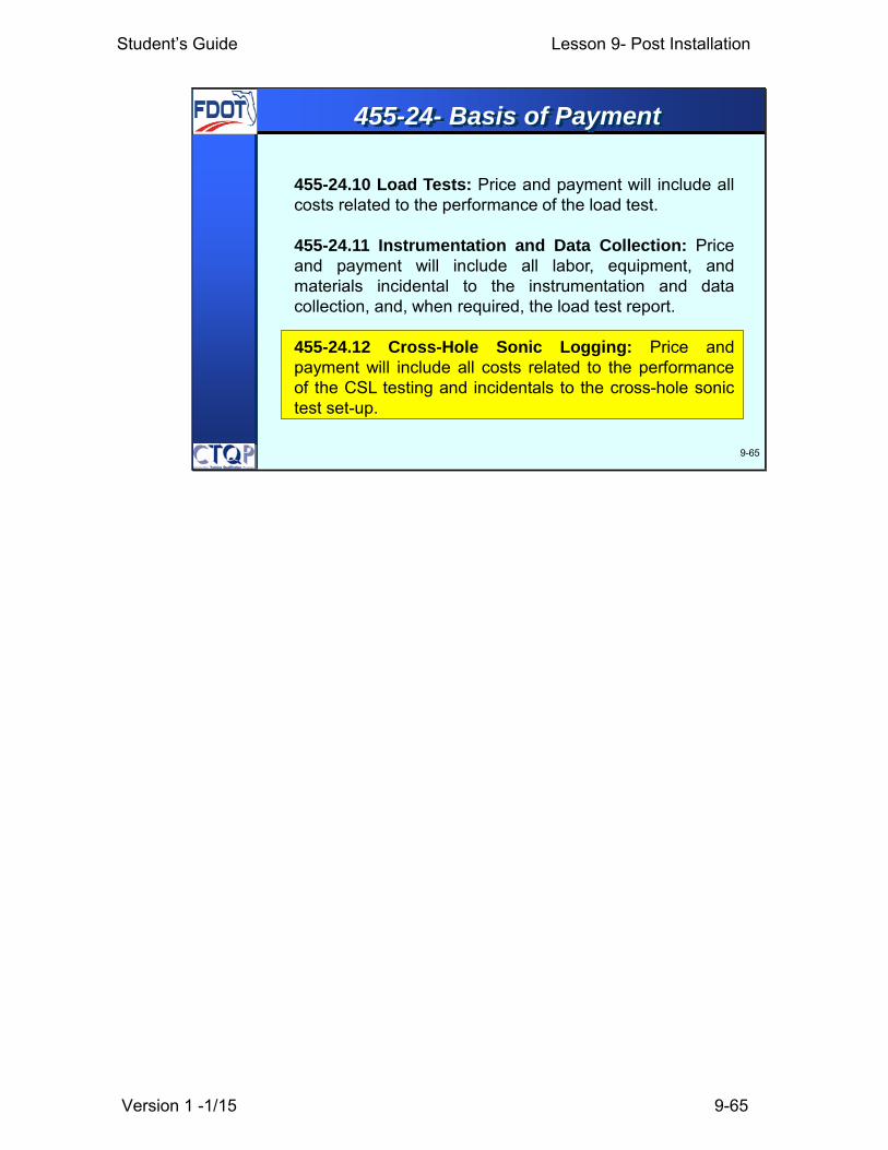
455-24.10 Load Tests: Price and payment will include allcosts related to the performance of the load test.
455-24.11 Instrumentation and Data Collection: Priceand payment will include all labor, equipment, andmaterials incidental to the instrumentation and datacollection, and, when required, the load test report.
455-24.12 Cross-Hole Sonic Logging: Price andpayment will include all costs related to the performanceof the CSL testing and incidentals to the cross-hole sonictest set-up.

Student’s Guide Lesson 9- Post Installation
Version 1 -1/15 9-66
9-66
455-24- Basis of Payment
455-24.13 Payment Items: Payment will be made under:
Item No. 455-18 - Protection of Existing Structures - lump sum.Item No. 455-88 - Drilled Shaft - per foot.Item No. 455-107 - Casing - per foot.Item No. 455-111 - Core (Shaft Excavation) - per foot.Item No. 455-119 - Test Loads - each.Item No. 455-122 - Unclassified Shaft Excavation - per foot.Item No. 455-129 - Instrumentation and Data Collection - lump
sum.Item No. 455-142 - Cross-Hole Sonic Logging - each.
Student’s Guide Lesson 9- Post Installation
Version 1 -1/15 9-67
9-67
Construction & Pay Summary
1
2
3
4
5
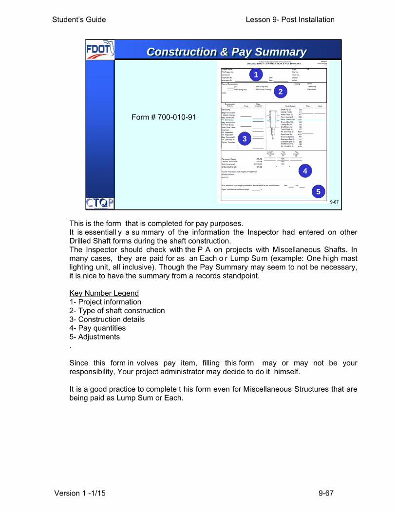
Form # 700-010-91
This is the form that is completed for pay purposes. It is essentiall y a su mmary of the information the Inspector had entered on other Drilled Shaft forms during the shaft construction. The Inspector should check with the P A on projects with Miscellaneous Shafts. In many cases, they are paid for as an Each o r Lump Sum (example: One high mast lighting unit, all inclusive). Though the Pay Summary may seem to not be necessary, it is nice to have the summary from a records standpoint. Key Number Legend 1- Project information 2- Type of shaft construction 3- Construction details 4- Pay quantities 5- Adjustments . Since this form in volves pay item, filling this form may or may not be your responsibility, Your project administrator may decide to do it himself. It is a good practice to complete t his form even for Miscellaneous Structures that are being paid as Lump Sum or Each.
Student’s Guide Lesson 9- Post Installation
Version 1 -1/15 9-68
9-68
Learning Outcomes
• Identify and describe various Integrity and Load Tests
• Construction tolerances
• Describe the Drilled Shaft Pay Items
• Identify the applicable 455 specifications
Student’s Guide Lesson 9- Post Installation
Version 1 -1/15 9-69
9-69
ANY QUESTIONS ?
Questions?

Project Name Page ofFIN Project No. Pier No.Contractor Shaft No.Inspected By Date StationApproved By Date Offset
NoneCasingType of ConstructionTemporaryWet/Slurry onlyDry
Wet/Slurry & casing PermanentWet/Casing only
Notes
ConstructionActivity
Datemm/dd/yyTime Shaft Details Plan Built
Set Casing Shaft Top El. STCasing Top El. CTBegin Excavation
WTWater Table El.(Below Casing)Perm Casing ID CIDBeg. Soil Excav.Perm. Casing OD CODFin. Soil Excav.Ground Surf. El. GSBeg. Rock Excav.
Fin Rock Excav. Casing Bot. El. CBShaft Diameter Top of Rock El.
SDRock Core TakenRTOverream
Rk. Core Top El. RCTInit. InspectionRock Core Dia. RCDFin. Inspection
Beg. Concrete Pl. RDRock Socket Dia.Overream Top El. OTFin. Concrete Pl.Overream Bot. El. Shaft Bottom El.
OBConstr. CompleteSB
Rk. Core Bot. El. RCB
LengthProvided
(ft)
PayFactor
F*
PayLength
(ft)
Permanent Casing Unclass. excavation
CT-CBGS-SB
STATE OF FLORIDA DEPARTMENT OF TRANSPORTATION
DRILLED SHAFT CONSTRUCTION & PAY SUMMARY CONSTRUCTION700-010-91
11/11
*Factor F to adjust shaft lengths, F=(2SDbuilt-SDplan)/SDbuilt(455-23)
Rock Core lengthDrilled Shaft length
Was additional shaft length provided for smaller shaft as per specifications:
If yes, indicate the additional length:
RCT-RCBST-SB x =
Yes: No:
ft
N/AN/AN/A