lesson 9: reactor protection module 1: … library/20041609.pdfiaea - candu i&c snerdi, shanghai...
TRANSCRIPT

IAEA - CANDU I&CSNERDI, Shanghai
Lesson 9: Reactor ProtectionModule 1: Reactor Shutdown Systems
page 9 – 1 - 1
Lesson 9: REACTOR PROTECTION
MODULE 1: REACTOR SHUTDOWN SYSTEMSREACTOR SHUTDOWN SYSTEMS OBJECTIVES:
At the end of this module, you will be able to:
1. Briefly describe the rationale for having two shutdown systems.2. Name the two shutdown systems for CANDU and state the preferred system for recovery purposes.3. Explain the difference between an absolute and a conditional trip4. Define reactor period and state a typical value.5. Sketch a simplified triplicated contact trip circuit and explain the operation.6. Explain why the other reactivity devices would be interlocked with the shutdown system.7. Describe how the marginal Shutdown Rod drop test can be performed.8. Explain the operation of a typical trip channel circuit.9. Sketch and describe the operation of a triplicated gas injection valve manifold.10. Sketch a channel of SDS2 to show gas injection and interspace valves with solenoid valves11. Describe precautions taken to prevent ground faults from disabling a trip channel.

IAEA - CANDU I&CSNERDI, Shanghai
Lesson 9: Reactor ProtectionModule 1: Reactor Shutdown Systems
page 9 – 1 - 2
MODULE 1: REACTOR SHUTDOWN SYSTEMS
Introduction
• The shutdown systems are designed toshut down the reactor for all plantconditions to prevent a potentiallyhazardous situation from occurring.
• To ensure high shutdown reliability twocompletely independent systems areprovided:
• ShutDown System 1 (SDS1)• ShutDown System 2 (SDS2)
• SDS2 is designed to operate at higher'trip' setpoints than SDS1 and ensuresa reactor shutdown should SDS1 beunavailable.
• Both shutdown systems are designedto quickly insert sufficient negativereactivity into the core to reduce thereactor power output to a safe,subcritical, low level. Figure 1: Typical CANDU Shutdown System Block Diagram.

IAEA - CANDU I&CSNERDI, Shanghai
Lesson 9: Reactor ProtectionModule 1: Reactor Shutdown Systems
page 9 – 1 - 3
Trip Conditions• The conditions which would cause the shutdown systems to come into operation are:
(1) Loss of reactor regulation.(2) Loss of effectiveness of the primary heatsink.
• SDS1 is designed to meet all the necessary safety conditions and yet allow the reactor to be quicklyrestored to operational conditions without exceeding the Xenon poisoning out period ofapproximately 40 minutes.
• SDS2, as a backup method, is more extensive and its operation will mean that a poisoning out due toXenon will occur as the recovery period from a SDS2 trip will be well in excess of 40 minutes.
• To meet shutdown system requirements, it is necessary to monitor several key parameters at all times.
• These parameters have "trip" values assigned which are very conservative with respect to theanalyzed safety values.
• These 'trips' are either absolute (i.e., valid at all states of reactor power), or conditional (i.e., available onlyabove 2% FP).
• Loss of reactor regulation is detected by continuously monitoring both gross neutron flux levels andthe rate of increase in neutron flux levels by means of neutron detectors.
• It is necessary that these detectors should be fast acting so that safety action is initiated as soon asthe trip parameter is exceeded.

IAEA - CANDU I&CSNERDI, Shanghai
Lesson 9: Reactor ProtectionModule 1: Reactor Shutdown Systems
page 9 – 1 - 4
Reactor Period
• Recall that the rate of change of neutron population (and hence, reactor power) essentially follows alogarithmic function.
• The time taken for reactor flux to increase by a factor 'e’ (base of natural logarithms, equal to 2.718) isdefined as the reactor period.
• Typical reactor periods for CANDU systems are reasonably long (in the order of 100 sec).
• The trip parameter for rate of change of reactor power is set for a reactor period of 10 sec(approximately 10% of usual reactor period) and is defined as the Rate Log Trip.
• A ten second reactor period corresponds to a rate of change in power increase of 10% present powerper second. (Note: this is 10% of the power level existing at any state of reactor operation).
• Rate Log is the abbreviated form of Rate of Change of the Logarithm of Neutron Flux.
• The high neutron power limit is a basic design parameter and is set to a level at which fuel bundlemaximum over power ratings are not exceeded.
• These neutronic trip parameters are absolute.
• Another absolute trip parameter is high heat transport system pressure.
• This pressure trip value is likely to be exceeded if the heat sink capacity on the steam generator sideof the heat transport system is drastically reduced. For example, an in complete tripping of theturbine could cause a high heat transport system pressure condition.

IAEA - CANDU I&CSNERDI, Shanghai
Lesson 9: Reactor ProtectionModule 1: Reactor Shutdown Systems
page 9 – 1 - 5
Reliability Considerations
• Conditional trips are armed automatically at an output level of greater than 2% full power. Below thislevel of power it has been demonstrated by analysis that these trip parameters are not critical to safereactor operation. Protection will still be provided at low power levels by the absolute trips.
• In order to meet the requirement of continuous availability, it is essential at least one of the specialshutdown systems be available at all times.
• Each SDS should be designed, operated and maintained as closely to 100% reliable as practicable.
• The equipment chosen should therefore be of the highest quality with key items triplicated.
• It is also essential that the system should be available for testing at all times and this, together withany maintenance requirements, implies that each trip system should have more than one channel.
• In fact, each system, SDS1 and SDS2, consists of three separate and independent channels (ChannelsD, E and F for SDS1 and Channels G, H and J for SDS2) with a requirement that two of the threechannels must exceed the setpoints before a reactor trip is initiated. This removes the possibility ofspurious trips causing a reactor shutdown.
• It should also be noted that equipment used on shutdown systems is allocated exclusively to reactorshutdown protection and for no other purposes.
• In addition, interlocks are provided such that if a shutdown system has been operated, it is notpossible to insert any positive reactivity into the reactor core by, for example, insertion of boosterrods or removal of adjuster rods.
• This eliminates the possibility of the reactor power increasing while the original fault condition stillexists.

IAEA - CANDU I&CSNERDI, Shanghai
Lesson 9: Reactor ProtectionModule 1: Reactor Shutdown Systems
page 9 – 1 - 6
Shutdown System One
• This system consists of multiple, stainless steelencased, hollow cadmium rods which drop, undergravity, into the reactor core in the event of a trip.
• The rods are an effective and distributed neutronabsorber which quickly reduce the reactor power to asafe, subcritical, low level.
• These rods are retracted on cables which areconnected to a winch via an electromagnetic clutchand are normally suspended out of core in the'poised' state.
• Each individual trip channel can be triggered if anytrip parameter for that channel is exceeded.
• The system must be fail safe so that in the event of anequipment or power failure, the shutdown systemwill activate and the reactor will be shut down.
• The general method of achieving this fail-safecondition is to ensure that the shutdown systemoperates when consitituent devices are de-energized.
Figure 2: Shutdown System One Schematic.

IAEA - CANDU I&CSNERDI, Shanghai
Lesson 9: Reactor ProtectionModule 1: Reactor Shutdown Systems
page 9 – 1 - 7
SDS1….Continued
• The relays associated with the individual tripparameter detectors (RL1, 2 & 3; HN1, 2 & 3; HTS1, 2 &3) are energized when the reactor is operatingnormally (i.e. not tripped).
• The individual relay contacts (1RL1 etc.) are thereforeclosed and thus, relays D, E and F are energized. Thecontacts D1, D2, E1, E2, F1 and F2 are also closed and acurrent path exists through the electromagneticclutch.
• This clutch, when energized, holds the shutdown rod,suspended on its cable, out of the reactor core. Thisarrangement of relay contacts is known as atriplicated contact set. It ensures that the two out ofthree requirement for tripping is maintained.
• In practice, there are multiple sets of Relays D, E andF. Each triplicated contact set controls one pair ofshutdown rods.
• Consider, for example, a Rate Log Trip occurring on Channel D. Relay RL1 will de-energize openingcontact 1RL1. This will cause relay D to de-energize with the consequent opening of contacts D1 andD2.
Figure 3: SDS1 ControlSchematic.
IAEA - CANDU I&CSNERDI, Shanghai
Lesson 9: Reactor ProtectionModule 1: Reactor Shutdown Systems
page 9 – 1 - 8
SDS1….Continued
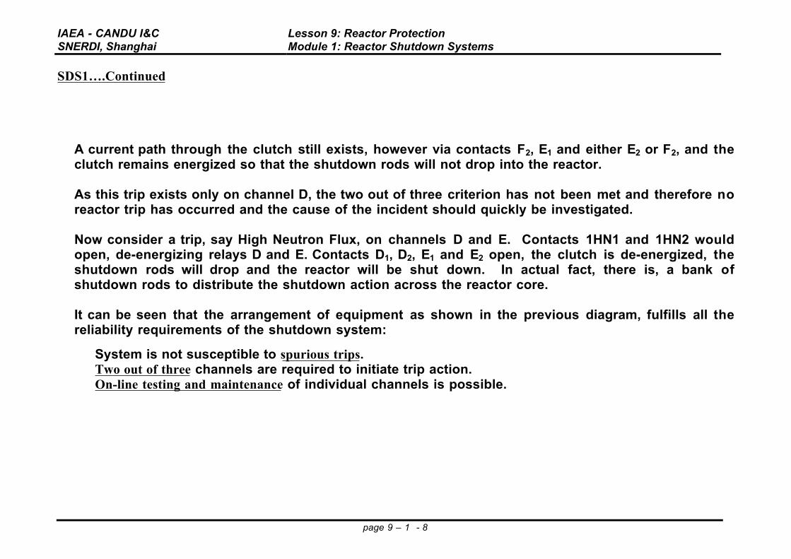
• A current path through the clutch still exists, however via contacts F2, E1 and either E2 or F2, and theclutch remains energized so that the shutdown rods will not drop into the reactor.
• As this trip exists only on channel D, the two out of three criterion has not been met and therefore noreactor trip has occurred and the cause of the incident should quickly be investigated.
• Now consider a trip, say High Neutron Flux, on channels D and E. Contacts 1HN1 and 1HN2 wouldopen, de-energizing relays D and E. Contacts D1, D2, E1 and E2 open, the clutch is de-energized, theshutdown rods will drop and the reactor will be shut down. In actual fact, there is, a bank ofshutdown rods to distribute the shutdown action across the reactor core.
• It can be seen that the arrangement of equipment as shown in the previous diagram, fulfills all thereliability requirements of the shutdown system:
• System is not susceptible to spurious trips.• Two out of three channels are required to initiate trip action.• On-line testing and maintenance of individual channels is possible.
Figure 4: Current Monitoring and Partial Drop Test Circuitry.

IAEA - CANDU I&CSNERDI, Shanghai
Lesson 9: Reactor ProtectionModule 1: Reactor Shutdown Systems
page 9 – 1 - 9
Marginal Rod Drop Testing and Circuit Status Logic
Figure 4. Marginal drop Test Feature in the Clutch Control Circuit
• To enable testing, and to give further indications to the operator of equipment serviceability,modifications to the triplicated contact set are made by the addition of resistors R1, R2 and R3 in oneleg of the contact set.
• Under normal operating conditions, with all contacts closed, the preferential (low resistance) currentpath will be via contacts D2, E2 and F2 with a higher current indication shown on the ammeter M1.
• Should a trip occur on just one channel, say D1 contacts D1 and D2 will open and the current path tothe clutch will now be via E2, F2 and E1. (Note: only one channel tripped, so no shutdown).
• The presence of R2 will lower the current flowing in the circuit with a new, lower, indication shown onM1.
• This, in addition to a warning annunciation lamp, will indicate to the operator that one channel hastripped.

IAEA - CANDU I&CSNERDI, Shanghai
Lesson 9: Reactor ProtectionModule 1: Reactor Shutdown Systems
page 9 – 1 - 10
System Reliability and Testing
• To ascertain full system reliability, it is also necessary to check that the shutdown rod is free to drop,when the clutch is de-energized.
• It would not be desirable, due to the large local negative flux transient which would occur, tocompletely drop any one rod for its full distance into the core for testing at power.
• If we can arrange to drop the rod for a limited distance only, we can be reasonably certain that theSDR has freedom of motion and that, in the event of a trip, the rod is able to drop to its limit.
• This procedure is known as a Marginal Drop Test and is performed, on one rod at a time, by thefollowing means:
• Relay contact 1TR1 is normally closed (Relay TR1 - de-energized). • Resistor R4 is adjusted such that, when in circuit, (i.e., when 1TR1 is open) the current flowing
through the clutch will be reduced such that the clutch can not quite sustain the load, and the rodwill drop.
• Relay TR1 is a timer relay.• Operation of the Marginal Drop Test switch button will energize the relay for a period of about, 0.2
sec.• During this time interval 1TR1 will open, R4 will be in circuit, clutch current will be reduced and the
shut off rod will begin to drop.• The distance dropped (typically 1.2 metre) will be indicated on a rod position meter.
• The contact TR1 will then close, the clutch is re-energized and the rod will be retracted to the 'poised'position by means of the motor driven winch.
• Operation of the Manual Trip will de-energize all three channels independent of trip logic status.

IAEA - CANDU I&CSNERDI, Shanghai
Lesson 9: Reactor ProtectionModule 1: Reactor Shutdown Systems
page 9 – 1 - 11
Shutdown System Two
• Shutdown system two is similar to shutdown system one with the following differences:• Higher trip set points.• The final negative reactivity device.
• All CANDU units built after 1975 have aSDS2 that operates by injecting asuitable neutron absorbing liquid(poison) into the reactor. The poisonchosen is Gadolinium Nitrate.
• The system has a two out of three tripcircuit using control valves to applythe high pressure injection gas insteadof relay contacts.
• The valves used are air to close style so that following a loss of instrument air, the valves will failopen and a reactor shutdown (fail safe) will occur.
• In the event of a trip, the air supply to the valves is dumped via electrically operated solenoid valves.• If any two of the three pairs of valves open, a flow path will be established between A and B, allowing
the high pressure cover gas to inject the poison into the moderator.• In actual fact, there are interspace vent valves located between the injection valves to keep the
interspace pressure low in case the upstream valve leaks. These interspace vent valves will close on atrip signal to maintain the interspace integrity. However, if the interspace vent valves should fail open,their capacity is restricted so that injection will still occur.
Figure 5: SDS2 Control valve Arrangement.

IAEA - CANDU I&CSNERDI, Shanghai
Lesson 9: Reactor ProtectionModule 1: Reactor Shutdown Systems
page 9 – 1 - 12
Poison Injection System
• Some of the general principles introduced in this lesson can be demonstrated by examining thepoison injection system (SDS2) utilized for a CANDU reactor.
• The triplicated channels are designated as G, H and J and can be activated manually or by such tripparameters as rate log,high neutron power, orhigh primary heattransport pressure.
• The helium storagetank is maintained atapproximately 8 MPa.
• Trip action must berequested by at leasttwo of the threechannels to initiatepoison injection.
Figure 6: Simplified Schematic for SDS2.

IAEA - CANDU I&CSNERDI, Shanghai
Lesson 9: Reactor ProtectionModule 1: Reactor Shutdown Systems
page 9 – 1 - 13
Poison Injection
• The poison injection valves will open and applythe stored helium pressure to the gadoliniumnitrate in the seven storage tanks.
• The poison is forced through the seven injectionnozzles by the helium pressure so that it issprayed into the centre of the reactor core.
• The poison tanks each contain a polyethyleneball which floats on the surface of the poison.Once the poison is injected, the ball will beforced onto the lower seat in the poison tankwhich prevents the helium gas from over-pressurizing the calandria.
Figure 7: Gadolinium Poison Tank.

IAEA - CANDU I&CSNERDI, Shanghai
Lesson 9: Reactor ProtectionModule 1: Reactor Shutdown Systems
page 9 – 1 - 14
Injection Valve Logic
• The triplicated valve configurationconsists of the six injection valves(MV1G, 2G; MV1H, 2H; MV1J, 2J) and thethree interspace vent valves (MV3G,MV3H, MV3J).
• All nine of these valves are of the air toclose, quick-open type.
• The poison injection valves will havesome seat leakage when the valves areclosed.
• With the large pressure differential acrossthe closed valve, a substantial pressurecould build up between the two injectionvalves.
• This would then result in pressureleakage across the second injection valveand the possible accidental injection of the poison into the moderator.
• To counteract this problem, the interspace vent valves are held open as long as the channel isenergized (i.e. not tripped).
• These valves will vent the interspace so that the seat leakage of the poison injection valves is not aproblem.
Figure 8: Connections to Injection and Vent Solenoid Valves.

IAEA - CANDU I&CSNERDI, Shanghai
Lesson 9: Reactor ProtectionModule 1: Reactor Shutdown Systems
page 9 – 1 - 15
SDS2 System Operation
• Assume channels G and J are energized (refer to Figure 9).
• Then SV1G, SV2J, and SV3G will all be energized so that the 700 kPa(g) signal is applied to MV1G andMV2J holding these injection valves closed.
• MV3G is able to vent through SV3G so that the interspace vent valve will be open.
• Should a trip occur, these solenoid valves would become de-energized, allowing the injection valvesto open and the interspace vent valves to close.

IAEA - CANDU I&CSNERDI, Shanghai
Lesson 9: Reactor ProtectionModule 1: Reactor Shutdown Systems
page 9 – 1 - 16
SDS2 Trip Channel
• A simplified trip channel (forexample G in Figure 9) canbe considered for thisinjection system.
• For simplicity, consider onlyhigh neutron power or rate logas the parameters which willactivate SDS2.
• Assume a rate log tripoccurs so that relay R2 isde-energized.
• Immediately contacts 2C1and 2C2 will open andremove power from relay R3
and the three solenoidvalves (1G, 2G & 3G) .
• The poison injection valves willdrive open and the vent valve will close due to the change in status in the solenoid valves. Contact3C1 will open since relay R3 was de-energized.
• Notice that if only channel G had tripped, a complete injection would not occur.
• Two of the channels must request safety action before a trip can occur.
Figure 9: Simplified Trip Channel G for SDS2.

IAEA - CANDU I&CSNERDI, Shanghai
Lesson 9: Reactor ProtectionModule 1: Reactor Shutdown Systems
page 9 – 1 - 17
Operating Considerations
• If this was a spurious trip, the rate log contacts would reclose, but the channel would not beenergized since the trip was latched in by relay R3.
• Operating staff would have to depress pushbutton PB1 to reset the channel.
• Pushing PB1 will apply power to R3, SV1G, SV2G, and SV3G. Contact 3C1 will close so that power ismaintained to the equipment mentioned when the pushbutton is released (3C1 bypasses PB1).
• The channel has been restored or reset to its pretrip status.
• Testing and maintenance can be carried out on individual channels without tripping the reactor. Thecontrol valve state, i.e., closed for normal operation, is verified by control room indication.
Normal System Operation (SDS1 and SDS2)
• During normal reactor operation, both shutdown systems must be available and operational at alltimes.
• The minimum number of shutdown rods to guarantee reactor shutdown (safety bank) must also beavailable.
• Maintenance of more than one channel at the same time is not allowed.• Testing and maintenance should be performed with the reactor at full power in order to verify the full
power trip settings. • Various control room indications are available to ascertain that the systems are fully operable.• The flux detectors can be tested by driving a boron shutter which is a neutron absorber located near
the detector.• his should result in a rise in indicated neutron flux readings which has the effect of testing the
complete channel for both Rate Log and High Neutron Flux. • Control room indications are also available to verify that supply voltage to the neutron detectors is
present and at the correct value.Normal System Operation (SDS1 and SDS2)…continued

IAEA - CANDU I&CSNERDI, Shanghai
Lesson 9: Reactor ProtectionModule 1: Reactor Shutdown Systems
page 9 – 1 - 18
• During normal (i.e., safe) conditions, certain changes in reactor operation are necessary which, if notcompensated for, could produce situations where trip parameters would be exceeded unnecessarilywith shutdown of the reactor occurring.
• Consider for example, requests for increases in power output. Power increases are computercontrolled, and applied at a rate such that the High N and the Rate Log Trip Setpoints should not beexceeded.
• It is necessary at these times that the operator visually checks the neutron instrumentation to ensurethat trip settings will not be exceeded.
• Refuelling can cause large fluctuations in neutron detector output.
• This is due simply to the physical movement of neutron absorbers (metal fuelling ram extension orspent fuel), or neutron producers (fresh fuel) between the detectors and the usual neutron source(reactor core).
• Increased instrumentation surveillance is necessary during refuelling to ensure that compensation ispresent and that the Neutron Flux (High Neutron and Rate Log) trip parameters are not likely to beexceeded.
• Use of welding equipment can induce a voltage spike which can trip a channel
• Maintenance on trip channel instrumentation cab initiate a quickly changing signal

IAEA - CANDU I&CSNERDI, Shanghai
Lesson 9: Reactor ProtectionModule 1: Reactor Shutdown Systems
page 9 – 1 - 19
Abnormal Operating Conditions
• Should a single channel trip, the operator must first establish, by instrumentation inspection, whetherthe trip was genuine or due to equipment malfunction or noise.
• In the event of a genuine trip due to a transient condition occurring on just one channel (e.g., duringrefuelling) the channel may be reset after the transient has subsided.
• If the trip was the result of equipment failure, the channel must be rejected, the necessary approvalfor maintenance must be obtained, and the work carried out.
• If for any reason, a single channel has been worked on during an outage, that channel must berejected (ie placed in the trip condition) until normal operating (full power) conditions have beenattained to permit the proper testing under in-service conditions.
• Normal testing and maintenance must be carried out at full power.• In the event of a complete reactor trip, it is first necessary for the operator to establish, from the
instrumentation and read-out devices, the cause of the trip. • The operator must then decide whether it is possible to diagnose and clear the fault within thirty
minutes and thus be able to restore criticality before poisoning out.• Should a shutdown rod become trapped in the core (say faulty marginal drop test), this condition will
be indicated by the appropriate shutdown rod position meter. • Severe local flux distortions will result. These local negative reactivity excursions may be partially
corrected by other reactivity devices, (e.g., adjuster rods and liquid zone level adjustment). • However, the reactor power output must be reduced to avoid local fuel overrating and possible fuel
failure.• Care must also be taken when operating with the heat transport system at reduced pressure. The
heat transport system could boil if the pressure is allowed to fall too low. • This will result in cavitation of the main HTS pumps and a low flow condition may develop which
could cause a conditional trip. • If boiling were allowed to persist, voiding in the fuel channels could occur. This condition would
case the reactivity to increase which could also trigger a neutron trip.

IAEA - CANDU I&CSNERDI, Shanghai
Lesson 9: Reactor ProtectionModule 1: Reactor Shutdown Systems
page 9 – 1 - 20
Grounding Problems
• Ground faults appearing in a trip channel circuit must not be able to make that channel fail unsafe.• Consider a simplified trip channel consisting of a power supply, a contact set, and a relay. De-
energizing the relay by opening the contact set will initiate safety action.• Ground faults can occur in a system as a result of physical abuse or dampness allowing a leakage
path. Imagine someone drilling through a tray bracket, and the drill bit nicks the insulation allowingthe conductor to contact the bracket screw. On the other hand, the insulation of a flexed portion ofthe cable may become cracked and split, and allow a current to flow to ground if the cable shouldbecome wet.
• The ground faults (G1 and G2)shown in Figure 10 can allow aground current flow (Ig).
• This ground current may besufficiently large to keep the relayenergized.
• In this case, the trip contacts canbe opened or closed, and therelay will remain energized.
• This is a potentially hazardoussituation where the ground faultshave caused the trip channel tofail unsafe - a requested trip would be ignored.
One solution to this problem that is employed in conventional instrumentation loops is to apply anintentional ground to the power supply.
Figure 10: A Simplified Trip Channel with Ground Faults G1 and G2.

IAEA - CANDU I&CSNERDI, Shanghai
Lesson 9: Reactor ProtectionModule 1: Reactor Shutdown Systems
page 9 – 1 - 21
Grounding• The disadvantage of applying an
intentional ground is that one groundfault appearing on the trip channel cannow cause a channel trip request.
• For example, if ground fault G1 appears asshown in Figure 11, the ground currenteffectively shorts out the relay.
• The relay is de-energized and safetyaction is initiated.
• This results in ground faults causing anunnecessary channel trip - but the tripchannel has failed safe.
• An improvement in the trip channel performance with ground faults can be achieved by duplicatingthe trip contacts on both sides of the tripchannel.
• If ground faults G1 and G2 should nowoccur, the top line of the trip channel wouldappear as a complete circuit regardless ofthe trip contact status.
• However, the second contact on the lowerline of the trip channel can still open thecircuit if a trip is requested. This channelwill now initiate safety action even with twoground faults (G1 and G2) present.
Ground Faults on the Triplicated Contact Set
Figure 11: A Trip Channel with an Intentional Ground (G1)
Figure 12: A Trip Channel with Duplicated Trip Contacts.

IAEA - CANDU I&CSNERDI, Shanghai
Lesson 9: Reactor ProtectionModule 1: Reactor Shutdown Systems
page 9 – 1 - 22
• Note that as the normal circuit is not referenced to ground at any point, the circuit will show completeimmunity to a single ground fault.
• More than one ground fault could affect the reliability of the circuit depending upon their locations.The worst possible location for multiple ground faults is at position A & B. This could by-pass thecontacts and disable one set of shutdown rods.
• However ground detection equipment is installed for Class II systems. This will inform staff that aground fault has occurred, enabling immediate corrective maintenance action to be initiated.
Summary
• The complete loss of electrical power to either shutdown system will result in a reactor trip.• Loss of air to the control valves for shutdown
system two will result in a reactor trip. • Remember also that operation of SDS2 will
automatically result in a poisoning out of thereactor.
• An overriding consideration in the design of both shutdown systems is that they must FAIL-SAFE. • In the event of equipment failure an erroneous trip is preferred to the possibility of no trip should a
safety parameter be-exceeded.• If the plant is to be in an operational state, the reactor protective system must be in a poised state in
order to provide safety action at all times.
Figure 13: Triplicated Contact Set.
IAEA - CANDU I&CSNERDI, Shanghai
Lesson 9: Reactor ProtectionModule 1: Reactor Shutdown Systems
page 9 – 1 - 23
MODULE 1: REACTOR SHUTDOWN SYSTEMS ASSIGNMENT
1. Briefly describe the rationale for having two shutdown systems.
2 . Name the two shutdown systems for CANDU and state the preferred system for recovery purposes.
3 . Distinguish between an absolute and a conditional trip and state two typical parameters for each tripgroup.
4. Sketch a typical relay contact configuration used to actuate SDS1. Explain the advantages of suchredundancy in a protective system, and discuss the general operation following a trip condition.
5 . Refer to Figure 5 and describe how the clutch current indication (M1) will change should channel Fbe de-energized, opening contacts F1 and F2.
6 . Explain why the other reactivity devices would be interlocked with the shutdown system.
7 . Sketch and describe the operation of a triplicated gas injection valve manifold.
8 . Sketch a channel of SDS2 to show gas injection and interspace valves with solenoid valves anddescribe the general operation for both poised and tripped states.
9. Describe precautions taken to prevent ground faults from disabling a trip channel.
10. Refer to Figure 10 and describe the circuit response following a rate log trip. State the purpose ofpush button PB1. Why are Relay 1 and 2 contacts duplicate on both sides of the trip channel?

IAEA – CANDU I&C Lesson 9: Module 2 SNERDI, Shanghai Protection System Computers & Safety Critical S/W
Page 9 – 2 – 1
Lesson 9: Computerized Shutdown SystemsModule 2: Trip Computer Systems and Safety Critical Software
• CANDU reactors are designed with two shutdown systems to provide a combined shutdown system unavailability targetof 10-6 years/year.
• These special shutdown systems are physically and functionally separate from the process control systems and fromeach other.
• Each reactor shutdown system is designed to be fully capable of independently shutting down the reactor when calledupon to do so.
• The special shutdown systems are designed, built and maintained to a very high quality assurance standard.
• These systems are designed to fail-safe so that safety action will always be provided, perhaps unnecessarily, in the eventof system or device failures (i.e. such as loss of power).
• Shutdown System Number One (SDS1) utilizes neutron absorbing rods (i.e. stainless steel coated cadmium rods) whichare poised above the reactor core (i.e. vertical core access) and drop by gravity upon a request for shutdown (i.e. de-energize the clutches holding the rods above the core).
• Shutdown System Number Two (SDS2) injects a liquid chemical neutron absorber into the core through horizontallymounted injection nozzles (i.e. horizontal core access) upon a request for shutdown (i.e. fail-open control valves aredriven open by venting to allow the poison injection to proceed).
• Note the diverse and independent reactor shutdown mechanisms.

IAEA – CANDU I&C Lesson 9: Module 2 SNERDI, Shanghai Protection System Computers & Safety Critical S/W
Page 9 – 2 – 2
Computerized Shutdown Systems…..continued
• For reliability purposes and to ensure that no single failure prevents a necessary reactor trip, each system consists ofthree identical instrumentation and logic trip channels (i.e. triplicated).
• The system safety action is initiated if two of the three channels detect a condition requiring reactor shutdown. This isreferred to as 2 out 3 consensus logic.
• A single channel tripping will not trip the reactor but has placed only its channel output devices in the safe state andinitiated the corresponding alarms. Now either of the remaining channels can initiate safety action when that secondchannel also senses and responds to a trip parameter condition.
To date, there are four evolutionary phases of CANDU shutdown system trip logic design to present times from thetraditional analog approach to the fully computerized system. It is important to note that the shutdown system itself (i.e. thephysical system design) remained a consistent design over the years, but the control logic implementation strategy graduallybecome more and more computerized.
Typical Trip System Parameters
• It is worth considering typical shutdown system trip parameters for illustrative purposes. In each case the trip parameterand trip level is selected by safety analysis to ensure that the licensed fuel temperature limits are not exceeded. Theparameters will trip with an adequate margin to the analyzed safety limit to ensure continual safe performance.

IAEA – CANDU I&C Lesson 9: Module 2 SNERDI, Shanghai Protection System Computers & Safety Critical S/W
Page 9 – 2 – 3
Typical Trip System Parameters
Neutronics
1. Neutron Flux Level High - reactor power level is too high
2. Neutron Rate Log (Rate of Change of Logarithmic Power High) - rate of change in power is too fast
Process
3. Steam Generator Level Low - impending loss of principle heat sink
4. Feedwater Line Pressure Low - impending loss of principle heat sink
5. Pressurizer Level Low - unexpected low heat transport inventory
6. Heat Transport Pressure High - energy mismatch, reactor power too high
7. Heat Transport Pressure Low - impending heat transfer problems, boiling & cavitation
8. Heat Transport System Gross Flow Low - impending heat transfer problems
9. Reactor Building Pressure High - possible hot fluid leak in containment or loss of vacuum10. Moderator Level Low - possible overrating of those channels still moderated
11. Moderator Temperature High - lower subcooling margin for moderator
Manual
12. Manual Channelized (i.e. D, E & F) Trip Pushbuttons (with common or individual capability)

IAEA – CANDU I&C Lesson 9: Module 2 SNERDI, Shanghai Protection System Computers & Safety Critical S/W
Page 9 – 2 – 4
Traditional Shutdown System Trip Logic - original design
• A shutdown system consists of process and neutronic sensors, reactivity devices, comparator logic instrumentation,man-machine interfacing (MMI) devices as well as cabling and interfacing relays.
• If any of the trip parameters are sensed to be operating beyond the acceptably safe margin to the analyzed unsafe state(i.e. power level too high, coolant flow too low, etc), then that parameter in that channel is recognized as being trippedand so the channel is de-energized in an attempt to trip the system (and thereby the reactor).
• As mentioned before, 2 out of 3 majority voting must occur before the system is tripped.
• Once two channels are tripped or de-energized, the final reactivity device control circuits are de-energized and safetyaction is initiated (e.g. shut down rods drop into core or liquid poison is injected) to shutdown the reactor.
• Even if one shutdown system does trip the reactor, the alternate Special Safety System remains poised in readiness toalso trip the reactor, if called upon to do so, independent of the actions of the other shutdown system.

IAEA – CANDU I&C Lesson 9: Module 2 SNERDI, Shanghai Protection System Computers & Safety Critical S/W
Page 9 – 2 – 5
Figure 1. Conventional Shutdown System Analog Instrumentation Configuration

IAEA – CANDU I&C Lesson 9: Module 2 SNERDI, Shanghai Protection System Computers & Safety Critical S/W
Page 9 – 2 – 6
Traditional Shutdown System Trip Logic - Operator Interfacing
• All trip signals, trip setpoints and trip status information are continuously displayed in the main control room viaconventional instrumentation devices.
• Manual controls allow the operators to periodically test the shutdown system channel devices from sensor to finalreactivity device.
• Note that an entire channel can be tripped during a test condition but that the reactor would still be operated at powersince a second channel has not tripped.
• The unavailability target for each special shutdown system of 10-3 yrs/yr (i.e. 8.76 hours per year) must be verified byan on-going shift-based testing program to demonstrate the availability of the system to function if called upon to do so.
• The trip logic in this design is implemented by relay logic , operator displays are small panel mounted meters andlights while operator controls are pushbuttons or handswitches.
• Data monitoring and logging was quite limited for this design and usually consisted of multipen trend recorders.• This was an obvious area for human-system interfacing improvements.

IAEA – CANDU I&C Lesson 9: Module 2 SNERDI, Shanghai Protection System Computers & Safety Critical S/W
Page 9 – 2 – 7
Traditional Shutdown System Trip Logic with Monitoring Computers - First Evolution
• The shutdown system trip circuitry and man-machine interfaces remained fundamentally unchanged from thetraditional design - so that signal comparisons, decision making, trip initiation and man-machine interfacing remainedas originally designed and proven functional.
• However, a new monitoring computer system was connected to the trip channels by rigorously buffered unidirectionalinterfaces.
• These one-way buffered interfaces were designed and tested to ensure that no faults in the computer system couldpossibly be propagated back into the trip circuit to degrade or disable the trip circuit functions.
• Once the safety system data was available within a computer system, then unlimited data manipulations, statisticalchecks and comparisons could be made along with flexible and informative display capabilities.
• The monitoring computer system improvement consisted of a remote multiplexor, located in each shutdown systemchannel, which obtains the channel parametric data.
• This data can then be displayed on convenient bar chart or analog trend displays on a selected CRT in the main controlroom.
• The computer can also give the operator an early warning if a variable is detected too close to a setpoint (i.e. impose anoperating margin threshold) , or for failed signals or signal discrepancies among similar signals.
• This manner of providing information to the operator can be much more user friendly while making it easier for theoperator to be aware of small changes or to be alerted early of an impending upset condition.

IAEA – CANDU I&C Lesson 9: Module 2 SNERDI, Shanghai Protection System Computers & Safety Critical S/W
Page 9 – 2 – 8
Figure #2 – Traditional Analog Shutdown System with a Computerized Monitoring Interface

IAEA – CANDU I&C Lesson 9: Module 2 SNERDI, Shanghai Protection System Computers & Safety Critical S/W
Page 9 – 2 – 9
Programmable Digital Comparators (PDC’s) - second evolution
• The next step taken in the evolution of the trip channel implementation was to digitize the process trip comparison andlogic circuitry by using digital microcomputers or programmable digital comparators (PDC’s) in place of the analogdevices.
• The shutdown system instrumentation still consists of the analog process and neutronic sensors and man-machineinterfacing devices as well as cabling and interfacing relays which remained fundamentally unchanged from thetraditional design. The neutronic trips were still implemented by the traditional analog circuits.
• But the process signal comparisons, decision making, and trip initiation were now moved to a programmable logicbase.
• Note that this method of design change is quite conservative so that the condition of the final configuration is alwaysknown. As well, an additional diversity was provided in that the neutronic trips were provided by analog logic while theprocess trips were initiated by digital logic - a gradual design progress was accomplished.
• The PDC’s are provided with a simple hardware timer-like device called a watchdog timer. The watchdog monitors theperformance of the PDC to ensure that expected operations are performed within an expected time interval to avoidsuch traps as an infinite loop execution or a stalled sequence.

IAEA – CANDU I&C Lesson 9: Module 2 SNERDI, Shanghai Protection System Computers & Safety Critical S/W
Page 9 – 2 – 10
Programmable Digital Comparators (PDC’s) ……continued
• If the conditions for the watchdog timer are not satisfied, that trip channel is de-energized independent of the tripparameter conditions (i.e the PDC has failed-safe)
• The logic in the PDC’s could now be programmed to implement conditioning logic, signal spread checks, rationalitychecks and calculate power dependent trip setpoints.
• In addition to outputting the trip channel signals, the PDC drives analog and digital outputs which drive conventionalindicating devices on the main control room panels.
• Correct operation of the PDC analog and digital outputs can be dynamically verified by wiring the outputs (analog &digital) back to special inputs (analog & digital).
• Periodic programs can then be executed to test drive the outputs and read back the corresponding field value developedby the output system. If significant discrepancies are recognized on the read-back, then an appropriate alarm can beannunciated to prompt operator or maintainer intervention.

IAEA – CANDU I&C Lesson 9: Module 2 SNERDI, Shanghai Protection System Computers & Safety Critical S/W
Page 9 – 2 – 11
Fully Computerized Shutdown System - third evolution
• The fully computerized shutdown system is a combination and extension of the PDC trip computers and the Monitoringcomputers strategies. The four special safety system functions (i.e. trip logic, testing, monitoring & display) areimplemented in a fully computerized design.
• The shutdown system parameter sensing instrumentation still consists of the analog process and neutronic sensors, butall of the comparison and trip logic, testing and monitoring functions along with the man-machine interfacing is nowcomputer based.
• The two shutdown systems (SDS1 and SDS2) have a similar computer configuration but each system is designed by aseparate team of designers as one measure to ensure functional independence and each design team specifies equipmentfrom a different manufacturer.

IAEA – CANDU I&C Lesson 9: Module 2 SNERDI, Shanghai Protection System Computers & Safety Critical S/W
Page 9 – 2 – 12
Figure#4 – Fully Computerized Shutdown System for Process and Neutronic Trip Parameters

IAEA – CANDU I&C Lesson 9: Module 2 SNERDI, Shanghai Protection System Computers & Safety Critical S/W
Page 9 – 2 – 13
Fully Computerized Shutdown System….continued
• Fifteen computers (15) , organized into a three level hierarchy, are used in the total computerized shutdown systemdesign for each reactor. The three hierarchy level functions are trip, display/test and monitoring
• There are channelized trip and display/test computers for each safety system channel.
• There are seven (7) SDS1 related computers.There are three SDS1 trip computers (i.e. Channels D,E & F) and threeSDS1 Display/Test (i.e. D/T) computers. A SDS1 monitoring computer is also provided to track and assess the tripparameters for this system by interfacing with the D/T computers so that seven computers are dedicated for SDS1.
• Similarly, there are seven (7) SDS2 related computers.There are three SDS2 trip computers (i.e. Channels G,H & J) andthree SDS2 Display/Test (i.e. D/T) computers. A SDS2 monitoring computer is also provided to track and assess the tripparameters for this system by interfacing with the D/T computers so that seven computers are also dedicated for SDS2.
• Finally, a unit monitoring computer (common to SDS1 & SDS2) is provided to coordinate the system performance andtesting data as well as administrative information from both the SDS1 and SDS2 monitoring computers.
• The data links to the unit monitoring computer are uni-directional from the individual safety system monitoringcomputer and are interlocked to allow data transmission from only one safety system at a time.

IAEA – CANDU I&C Lesson 9: Module 2 SNERDI, Shanghai Protection System Computers & Safety Critical S/W
Page 9 – 2 – 14
Fully Computerized Shutdown System….continued
• This results in 7 SDS1, 7 SDS2 and 1 unit computer for a total of 15 safety system computers.
• This configuration provides a central interface between the operator and the special safety systems while preserving therequired separation between different safety systems and among different channels of the same system by using uni-directional fibre-optic links and hardware interlocks. External hardware interlocks on both inputs and outputs ensuresthat only one channel can be tested or calibrated at a time.

IAEA – CANDU I&C Lesson 9: Module 2 SNERDI, Shanghai Protection System Computers & Safety Critical S/W
Page 9 – 2 – 15
Figure #5 – Configuration of Trip, Display/Test and Monitoring Computers for SDS1 & SDS2

IAEA – CANDU I&C Lesson 9: Module 2 SNERDI, Shanghai Protection System Computers & Safety Critical S/W
Page 9 – 2 – 16
CANDU NPP S/W Categorization Methodology for Safety, Plant Control, Monitoring & Testing Systems
This lecture will provide some insight into the S/W categorization methodology that should be taken into consideration forsafety critical software for computerized shutdown system applications.
Lecture topic summary includes:• Purpose of the S/W Categorization Process• Necessary Definitions• Specification of the S/W Categories• Categorization Process Basis• Determining Plant System Safety Significance• Determining S/W Failure Impact Type• Final S/W Category Determination• S/W Categorization 1-4 Summary

IAEA – CANDU I&C Lesson 9: Module 2 SNERDI, Shanghai Protection System Computers & Safety Critical S/W
Page 9 – 2 – 17
Purpose of the S/W Categorization Process
• Minimize any unnecessary reliance on S/W or S/W controlled systems for nuclear safety
• Ensure that S/W necessary for nuclear safety is clearly identified, understood and achieved
• Select the S/W Engineering practices which assures the reliability and safety of the S/W
• Categorize S/W with respect to its failure effect on nuclear safety

IAEA – CANDU I&C Lesson 9: Module 2 SNERDI, Shanghai Protection System Computers & Safety Critical S/W
Page 9 – 2 – 18
S/W Categorization Process - Necessary Definitions
• Safety-Related System - A plant system that, upon failure, has the potential to impact the radiological safety of thepublic or plant personnel due to the operation of the nuclear power plant (NPP).
• Nuclear Safety-Related Functional Requirements - those functional requirements which ensure that the system willfulfill its role in achieving acceptable levels of radiological safety with respect to the public and plant personnel
• Process System - a safety-related plant system whose role is to contribute, directly or indirectly to the production ofelectricity.
• Initiating Event - a malfunction of a plant system that would, in the absence of Special Safety System actions, lead to arelease of radioactivity which could result in doses exceeding the most restrictive regulatory dose limit for that station.
• Mitigating System - a safety-related system that has nuclear safety-related functional requirements to reduce theconsequences of an initiating event.
• Safety System Significance - a classification (into High, Medium or Low) of the plant system in terms of its importanceto nuclear safety
• Software Failure Impact - the impact of the failure of that S/W with respect to the nuclear safety related functionalrequirements of the host plant system
• Minimum Performance Requirements - the minimum amount of equipment, and the minimum functional andperformance characteristics of that equipment, necessary to achieve the plant system performance specified in thesafety analysis completed in support of that station operating license.

IAEA – CANDU I&C Lesson 9: Module 2 SNERDI, Shanghai Protection System Computers & Safety Critical S/W
Page 9 – 2 – 19
Specification of the S/W Categories
• The Software Category - is represented by a number from 1 to 4
• Category 1 S/W considered the most important to Nuclear Safety
• S/W Nuclear Safety Category 1 - is also referred to as Safety Critical Software
• Failure of Safety Critical S/W can result in a system with a high safety-related reliability requirement not meeting itsminimum performance requirements or can result in a serious initiating event (low frequency limit) in a processsystem.
• Category 4 S/W must have no importance to Nuclear Safety
• S/W Nuclear Safety Category 2 - Failure of this S/W can result in a serious process failure, or a degradation in theperformance of a mitigating system.
• There is a distinct reduction in safety significance from Category 1 S/W since the consequences of the Category 2 S/Wfailure can still be mitigated by special safety system action.
S/W Nuclear Safety Category 3 - Failure of this S/W does not prevent the affected plant system from meeting its NuclearSafety-related design intent or the affected plant system has a low safety significance.
IAEA – CANDU I&C Lesson 9: Module 2 SNERDI, Shanghai Protection System Computers & Safety Critical S/W
Page 9 – 2 – 20
Categorization Process Basis
Fundamental Basis - As the Safety Significance of the S/W decreases, less effort is required to be expended todemonstrate that the S/W meets its requirements.
Risk Based Approach to Nuclear Safety - The risk associated with the failure of a system to perform is a function of theProbability of the failure and the Consequences of the failure (the higher the risk associated with a failure, the higher theassurance must be that the S/W will not contribute to that failure).
Acceptable levels of plant risk are achieved by - Designing the plant to have a low probability of serious process failures,and by providing redundant mitigating systems that minimize the consequences of serious process failures, should theyoccur.
Two Phases for the Categorization Process
• Phase I; Determine the System’s Safety Significance
• Phase II; Determine the S/W Failure Impact

IAEA – CANDU I&C Lesson 9: Module 2 SNERDI, Shanghai Protection System Computers & Safety Critical S/W
Page 9 – 2 – 21
Two Phases for the Categorization Process
• Phase I; Determine the System’s Safety Significance - This involves identifying the safety significance (as High,Medium or Low) for the plant system of which the S/W to be categorized is a part.
• Safety Significance Determination - The safety significance is obtained by determining the system type (safety-related,mitigating, process, etc) and quantifying the systems reliability requirements
• It is also important to note that more stringent reliability requirements due to factors other than nuclear safety may beused (i.e. engineering judgment, experience, etc.) to justify selecting a more restrictive S/W category
• Phase II; Determine the S/W Failure Impact - This involves identifying and classifying the worst possible S/W failuremodes and effects in terms of impairment of plant safety functions.
• Failure Impact Types - The Failure Impact Type is identified as Type I, II or III with Type I representing a failure withthe greatest consequences with respect to Nuclear Safety.
Failure Impact Type Analysis - The determination of the failure impact type is based on an analysis of the role of the S/Wwith respect to the safety-related function of the system and on the independent mitigating provisions within the plantsystem which can mitigate the consequences of the S/W failure.

IAEA – CANDU I&C Lesson 9: Module 2 SNERDI, Shanghai Protection System Computers & Safety Critical S/W
Page 9 – 2 – 22
Failure Impact Type Considerations
• Assess all Failure Impacts - Within a plant system there can be sub-systems that perform multiple functions.
• The Failure Impact Assessment must identify all possible safety-related impacts of S/W failure on a plant system.
• For the purposes of categorization, the most severe S/W failure impact type should be used.
• Failure Impact - If the worst-case S/W failure is not Type I, then it is possible to reduce the stringency of the S/Wcategory because the role of the S/W within the plant system is less significant from a safety perspective than the roleof the overall plant system.

IAEA – CANDU I&C Lesson 9: Module 2 SNERDI, Shanghai Protection System Computers & Safety Critical S/W
Page 9 – 2 – 23
Definition of Plant Safety Significance values for Phase I use
• Safety & Mitigating Systems Safety SignificanceHigh Significance: Q .LE. 10-3 yr/yr (Q= unavailability req’mt)Medium Significance: 10-3 .LT. Q .LT. 10-1 yr/yrLow Significance: Q .GE. 10-1 yr/yr
• Process Systems Safety Significance - Process System FailuresHigh Significance: f .LE. 10-3 occ/yr (f= event frequency limit)Medium Significance: 10-3 .LT. f .LE. 10-2 occ/yrLow Significance: f .GT. 10-2 occ/yr
• Monitoring/Testing Systems Safety SignificanceHigh Significance: Q .LE. 10-3 yr/yr (Q= unavailability req’mt)Medium Significance: 10-3 .LT. Q .LT. 10-1 yr/yrLow Significance: Q .GE. 10-1 yr/yr

IAEA – CANDU I&C Lesson 9: Module 2 SNERDI, Shanghai Protection System Computers & Safety Critical S/W
Page 9 – 2 – 24
Four Steps to follow for Phase I - Determining Plant Safety Significance
• 1. Identify the Plant System or Systems Involved -Determine which plant systems the S/W or S/W controlled systemsare a part of or interact with and determining the role of the S/W.
• 2. Determine the Plant System Type - Identify each role for the plant system’s nuclear safety functions and determineif it is a special safety, mitigating, process or monitoring/testing system
• 3. Establish a Suitable Plant System Boundary -Selection of the boundary influenced by data availability by usingeither system unavailability requirements or the initiating event frequency limit
• 4. Determine the Plant System Safety Significance -High, Medium or Low

IAEA – CANDU I&C Lesson 9: Module 2 SNERDI, Shanghai Protection System Computers & Safety Critical S/W
Page 9 – 2 – 25
Four Steps for Phase II - Determining S/W Failure Impact Type
• 5. Identify All S/W Failure Modes & Effects -Assess the interactions of the relevant sub-systems that comprise the plantsystem to determine the possible failure impacts of the S/W for all conceivable failure modes.
• Credit S/W and Computer System Design Attributes - This is an optional additional step to consider the possibility ofS/W and computer system design attributes for preventing or minimizing specific failure modes.
• 6. Determine the limiting S/W Failure Impact Type - Apply the classification criteria to determine Type 1-3 FailureImpact Type
• 7. Determine the S/W Category -Use the determined plant system S/W failure Safety Significance (Column data) andthe S/W Failure Impact Type (Row Data) to find the S/W Category Matrix intersection value which is the S/WCategory value.
• 8. Determine the limiting S/W Category - This step is necessary when the application involves more than one systemor can be classified as more than one type. The most restrictive category should be used.
• Note that S/W categorization can be Iterative - An initial category may be determined and then further analysis may beinitiated in order to resolve any issues which arise during the design process

IAEA – CANDU I&C Lesson 9: Module 2 SNERDI, Shanghai Protection System Computers & Safety Critical S/W
Page 9 – 2 – 26
The Criteria for S/W Failure Impact for Safety or Mitigating Systems
• Type I - The designed nuclear safety functions will not be available or the minimum performance requirements ofthe plant system will not be met for some or all process system failures.
• Type II - The system’s functional performance is degraded for some or all process system failures but the minimumperformance requirements of the plant system will be met. Or the system’s redundancy is reduced such that theprobability of not meeting the minimum performance is increased
• Type III - The S/W failure has no impact on the nuclear safety functions of the plant system
The Criteria for S/W Failure Impact Type for Process Systems
• Type I - The S/W failure can, in the absence of safety or mitigating system actions, directly or indirectly causesystematic fuel failures or release of radioactivity which could result in doses exceeding the most restrictive regulatorydose limit for the station
• Type II - The S/W failure can directly or indirectly raise the temperature of the fuel but not lead to systematic fuel
failures. Or the S/W failure leads to an increase in probability of the Type I consequences of systematic fuel failure orreleases (probability)
• Type III - The S/W failure has no impact on the nuclear safety-related reliability performance of the nuclear safetyfunctions of the plant system

IAEA – CANDU I&C Lesson 9: Module 2 SNERDI, Shanghai Protection System Computers & Safety Critical S/W
Page 9 – 2 – 27
The Criteria for S/W Failure Impact Type for Testing Systems
• Type I - The S/W failure can cause the designed nuclear safety functions under test not to be available or theminimum performance requirements of the plant system under test not to be met for some or all process systemfailures
• Type II - The S/W failure causes an inaccurate test result or degrades the functional performance of the system undertest or causes a redundancy reduction in the system under test but the minimum performance requirements of the plantsystem will still be met for all process system failures.
• Type III - The S/W failure has no impact on the test or on the safety-related performance of the system under test.

IAEA – CANDU I&C Lesson 9: Module 2 SNERDI, Shanghai Protection System Computers & Safety Critical S/W
Page 9 – 2 – 28
S/W Categorization tabled as a function of Safety Significance & Failure Impact Type
System SafetySignificance
Impact Type I Impact Type II Impact Type III
High Cat. 1 Cat. 2 Cat. 4Medium Cat. 2 Cat. 3 Cat. 4Low Cat. 3 Cat. 3 Cat. 4
S/W Categorization 1-4 Process Summary
• Safety Critical S/W - The standard for Safety Critical S/W will only be applied to Special Safety Systems and toProcess Systems for which the initiating event frequency is less than 10-3 occ/yr.
• Reduction in S/W Rigour from Category 1 to 2 Occurs: If the system Safety Significance decreases from High toMedium while the S/W Failure Impact remains Type I, or if the Safety Significance remains High but the FailureImpact Type is reduced from Type I to Type II.
• Category III Application - If the system Safety Significance is Low and the S/W Failure Impact Type is I or thesystem has a Medium or Low Safety Significance and the Failure Impact Type is II.
• Category IV Application: - If the S/W Failure Impact Type is III (no Safety- Related Impact) the S/W is assessed asCategory IV.