lesson plan template -...
TRANSCRIPT

Take Flight! Page 1 of 12 Developed by IEEE as part of TryEngineering www.tryengineering.org
Take F light!
Provided by TryEngineering - www.tryengineering.org
L e sso n Fo cus Lesson focuses on flight and how the design of a glider will improve aerodynamic function. Teams of students explore the forces that impact flight and design, build, and test their own gliders out of simple materials.
L e sso n Syno p s is The "Take Flight" lesson explores how flight is possible and how engineers have improved glider designs and materials to improve flight accuracy and distance. Students explore the forces that make flight possible, and learn about how material choice and shape also impact flight. Students work in teams to design and test a simple glider using basic materials that can fly straight for a distance of fifteen feet.
Ag e L e ve ls 8-12.
O b je c t ive s
Learn about the forces that impact flight. Learn about engineering design, testing, and troubleshooting. Learn how engineering can help solve society's challenges. Learn about teamwork and problem solving.
Ant ic ip a te d L e a r ne r O utco me s As a result of this activity, students should develop an understanding of:
flight engineering design materials selection teamwork
L e sso n Ac t iv it ie s Students learn about flight and work in teams to design, build, and test a glider from simple materials that can fly straight for fifteen feet toward a target.
Alig nme n t to C ur r icu lu m Fr a me w o r ks See curriculum alignment sheet at end of lesson.
R e co mme nd e d R e a d ing
Jet Plane: How It Works, David Macaulay (ISBN: 978-1626722118) The Big Book of Airplanes, DK (ISBN: 978-1465445070) Flight (DK Eyewitness Books) (ISBN: 978-0756673178)

Take Flight! Page 2 of 12 Developed by IEEE as part of TryEngineering www.tryengineering.org
In te r ne t C o nne ct io ns
TryEngineering (www.tryengineering.org) NASA: The Wright Way (www.grc.nasa.gov/WWW/Wright) Next Generation Science Standards (www.nextgenscience.org) Common Core State Standards for Mathematics (www.corestandards.org/Math) International Technology Education Association's Standards for Technological
Literacy (www.iteea.org/39161.aspx) Computer Science Teachers Association K-12 Computer Science Standards
(www.csteachers.org/page/standards)
O p t io na l W r it ing Ac t iv it y
Write an essay or a paragraph about how glider technology has changed over the past hundred years. Or, write an essay about how you think the world has been impacted because people can fly.

Take Flight! Page 3 of 12 Developed by IEEE as part of TryEngineering www.tryengineering.org
Take F light!
Fo r T e a che r s : T e a che r R e so ur ce s
Lesson Goal The "Take Flight" lesson explores how flight is possible and how engineers have improved glider designs and materials to improve flight accuracy and distance. Students explore the forces that make flight possible, and learn about how material choice and shape also impact flight. Students work in teams to design and test a simple glider using basic materials that can fly straight for a distance of fifteen feet (extend the distance or limit materials for older students).
Lesson Objectives Learn about the forces that impact flight. Learn about engineering design, testing, and
troubleshooting. Learn how engineering can help solve society's challenges. Learn about teamwork and problem solving.
Materials Student Resource Sheets Student Worksheets Building materials for each team: a range of materials can be used for this lesson,
including cardboard, foam sheets, foil, foam trays, paperclips, rubber bands, popsicle sticks, balsa wood, paint stirrers, scotch tape, glue, paper, cardboard tubes. A few items that can provide weight should be available (coins, putty, clay). Additional tools to provide include a pencil, safe scissors, and a ruler.
Procedure 1. Show students the student reference sheets. Encourage students to read these and
investigate the different shapes of gliders for the prior night's homework. 2. To introduce the lesson, ask students to consider the different shapes and materials
they might use to build a glider. Depending on student level, discuss how weight might impact their design, and the shape or size of wings.
3. Divide class into teams of 2-3 "engineers." Explain that they need to design and then build and test a simple glider that can fly at least fifteen feet toward a target.
4. Student teams design their glider and create a paper template to guide construction. 5. Teams construct their glider using the template as a guide to cutting materials.
Instruct students that no flight testing is to be done during construction phase. 6. To flight test, identify a large target (bench, box, goal post) in outdoor setting so that
gliders fly away from students. The educator or other objective person should “fly” each glider so the strength of the launch is consistent. Each plane will be tested three times with the furthest distance of the three used to determine winning team.
7. Optional Redesign Phase. If time permits, allow teams to test their initial design, and then have the opportunity to revise or fine-tune their design based on how their initial design scored during flight test. Redesign is a normal part of all engineering design processes, so this step is important for students to experience if time allows.
8. Teams complete a reflection sheet observing their designs and those of their classmates, and share their experiences with the class.
Time Needed Two to three 45 minute sessions.

Take Flight! Page 4 of 12 Developed by IEEE as part of TryEngineering www.tryengineering.org
Take F light!
Stud e nt R e so ur ce : W ha t Fo r ce s Imp a ct F lig h t?
There are four forces that impact flight: Weight, Lift, Drag, and Thrust. All four forces have to be taken into consideration when designing and building a glider or airplane. In flight, each force has an opposite force that works against it. Everything has weight, which is a result of gravitational forces. The materials selected for a glider design will have a weight that will need to be offset by “Lift” in order to fly. Lift is an aerodynamic force that helps to counteract weight. The heavier an object is, the harder it is for lift to work againt it and achieve flight. But, the forward motion (velocity) or thrust of an aircraft through the air along with the shape of the aircraft and its parts, especially its wings, all impact how strong the force of lift will be! Many wings have a curved shape on top and are flatter on the bottom so air moves faster over the top. When air moves faster, the pressure of the air decreases. If the pressure on the top of the wing is lower than the pressure on the bottom of the wing, the difference in pressure helps lifts the wing up into the air. The last of the four forces impacting flight is drag….and this force works to slow a glider or plane. Drag is a force that acts opposite to the relative motion of any object moving with respect to surrounding air (or water!). For example, drag acts opposite to the direction of movement of a object such as a car, bicycle, airplane, glider, or boat hull. It is impacted by the shape and material selection of a plane or boat, as well as other factors, including the humidity of the air. It is also impacted by the the thrust or speed of the aircraft…the greater the thrust, the greater the drag. In the case of the glider to be built as part of this lesson…the thrust is generated by the person who will push your plane through the air during testing! For a motorized plane, it is the motor that provides propulsion and the power to move through the air. A plane may have several motors to generate thrust, and the design of the motor also impacts how the surrounding air is moved, which in turn impacts thrust and drag. All the forces impacting flight are interrelated. How a plane flies depends on the strength and direction of all four forces! If all are in balance, a plane will move along at a constant velocity. If there are any imbalances, the plane will move in the direction of that force…for example if weight overpowers lift, the plane will move down. A plane goes up if the forces of lift and thrust are stronger than gravity and drag. If gravity and drag are stronger than lift and thrust, the plane goes down.
Image Credit: NASA

Take Flight! Page 5 of 12 Developed by IEEE as part of TryEngineering www.tryengineering.org
Take F light!
Stud e nt R e so ur ce : T he W r ig ht B r o the r s
Orville Wright (August 19, 1871 – January 30, 1948, left) and Wilbur Wright (April 16, 1867 – May 30, 1912, right), were two brothers and aviation pioneers who are generally credited with inventing, building, and flying the world's first successful airplane. They made the first controlled, sustained flight of a powered, heavier-than-air aircraft on December 17, 1903, near Kitty Hawk, North Carolina, US. In 1904–05 the brothers further developed their flying machine into the first
practical fixed-wing aircraft. Although not the first to build and fly experimental aircraft, the Wright Brothers were the first to invent and fine tune aircraft controls that made fixed-wing powered flight possible.
The brothers' real breakthrough was their invention of three-axis control – this enabled a pilot to steer the aircraft and maintain equilibrium, or balance. This method still remains the standard for all kinds of fixed-wing aircrafts. While others of the era were focusing on making more powerful engines, the Wright brothers thought that finding a way to control an aircraft was the more pressing challenge.
Using a small homebuilt wind tunnel, the brothers tested and retested their ideas and designs. They collected lots of data that helped them design and build more efficient wings and propellers that could be controlled. Their first U.S. patent, 821,393, (see right) did not claim invention of a flying machine, but rather, the invention of a “system of aerodynamic control that manipulated a flying machine's surfaces.”
They gained the experience and skills essential for their success by working with printing presses, bicycles, motors, and other machines. Their work with bicycles in particular influenced their belief that an unstable vehicle like a flying machine could actually be controlled and balanced with practice! From 1900 until their first powered flights in late 1903, they conducted extensive glider tests that also developed their skills as pilots. More details on the Invention Process of the Wright Brothers can be found at https://wright.nasa.gov/overview.htm.

Take Flight! Page 6 of 12 Developed by IEEE as part of TryEngineering www.tryengineering.org
Take F light!
Stud e nt W o r kshe e t : Engineering Teamwork and Planning You are a team of engineers given the challenge of creating a glider out of simple materials that can fly as straight as possible toward a target that is fifteen feet away. You may use any materials provided to you and will first work as a team to develop a template for your glider. Planning and Design Phase Be sure to read the summary sheet about the forces that impact flight. It its simplest form, a glider can be considered to have three parts: the wings, the body (or fusilage), and the tail. The size, shape, materials, and weight of each will impact how well the glider will fly. Some gliders have a stabilizer on the tail or extra weight in the front to improve stability You can experiment with different materials to see what works best for your design. Your team has been provided with a set of materials. Review these as a group and draw a simple design for each part of your glider in the box below. Please also include a list of materials you think you'll need to build your glider. Then draw a full size template of your parts which can be used to cut and build your actual glider.
Materials Required for Building:

Take Flight! Page 7 of 12 Developed by IEEE as part of TryEngineering www.tryengineering.org
Take F light!
Stud e nt W o r kshe e t Construction Phase Gather your materials, review your plan, and build your glider. Your team can change its design in the building stage, if necessary, to improve the final result. Then, answer the questions below: 1. How similar was your final glider to your original design template? 2. If you found you needed to make changes during the construction phase, describe why your team decided to make revisions. 3. Did you find you needed to add additional materials during construction? What did you add, and why? 4. Do you think that engineers often change their original plans during the manufacturing phase of development? How do you think this might impact a planned design or manufacturing budget? 5. How did you decide which materials to select for final construction? What was it about the materials that you thought might help your glider fly? 6. How did you decide on the shape of the parts of your glider? What was it about the shape of each part that you thought might help your glider fly?
Take Flight! Page 8 of 12 Developed by IEEE as part of TryEngineering www.tryengineering.org
Take F light!
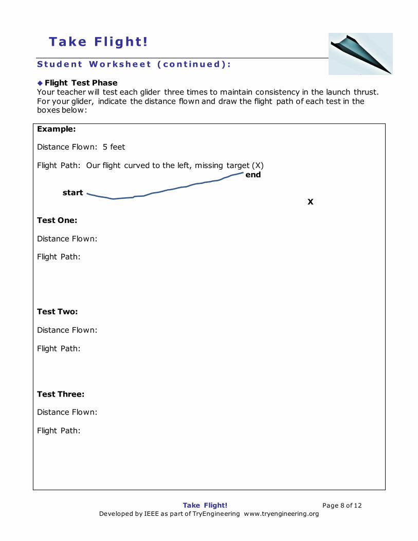
Stud e nt W o r kshe e t ( co nt inue d ) : Flight Test Phase Your teacher will test each glider three times to maintain consistency in the launch thrust. For your glider, indicate the distance flown and draw the flight path of each test in the boxes below:
Example: Distance Flown: 5 feet Flight Path: Our flight curved to the left, missing target (X) end start X Test One: Distance Flown: Flight Path: Test Two: Distance Flown: Flight Path: Test Three: Distance Flown: Flight Path:

Take Flight! Page 9 of 12 Developed by IEEE as part of TryEngineering www.tryengineering.org
Take F light!
Stud e nt W o r kshe e t ( co nt inue d ) : Evaluation Complete the evaluation questions below: 1. What aspect(s) of the design led to the success of the glider that flew the straightest and furthest? 2. What was the best aspect of your design? Describe one part of your design that you think worked the best. 3. If you had a chance to do this project again, what would your team do differently? 4. If you could have selected some building materials which were not made available to you, what would you have selected? Why? 5. Do you think this project worked better because you were part of a team, or do you think you could have done a better job working alone? 6. Do you think that engineers work alone, or in a team when they are developing new materials, processes, or products? 7. If your glider was scaled up in size to be the length of an average passenger car, how far do you think it would have flown?

Take Flight! Page 10 of 12 Developed by IEEE as part of TryEngineering www.tryengineering.org
Take F light!
Fo r T e a che r s : A lig nme n t to C ur r icu lu m S ta nd a r d s All lesson plans in this series are aligned to the Next Generation Science Standards, and if applicable also to the Computer Science Teachers Association K-12 Computer Science Standards, the U.S. Common Core State Standards for Mathematics, and the International Technology Education Association's Standards for Technological Literacy.
Next Generation Science Standards (grades 3-5) Students who demonstrate understanding can:
3-PS2-1. Plan and conduct an investigation to provide evidence of the effects of balanced and unbalanced forces on the motion of an object.
3-PS2-2. Make observations and/or measurements of an object’s motion to provide evidence that a pattern can be used to predict future motion.
3-5-ETS1-1. Define a simple design problem reflecting a need or a want that includes specified criteria for success and constraints on materials, time, or cost.
3-5-ETS1-2. Generate and compare multiple possible solutions to a problem based on how well each is likely to meet the criteria and constraints of the problem.
3-5-ETS1-3. Plan and carry out fair tests in which variables are controlled and failure points are considered to identify aspects of a model or prototype that can be improved.
5-PS2-1. Support an argument that the gravitational force exerted by Earth on objects is directed down.
U.S. Common Core State Standards for Mathematics (grades 3-5)
Grade Three: Represent and Interpret Data (CCSS.MATH.CONTENT.3.MD.B.4) Grade Four: Represent and Interpret Data (CCSS.MATH.CONTENT.4.MD.B.4) Grade Five: Represent and Interpret Data (CCSS.MATH.CONTENT.5.MD.B.2)
International Technology Education Association's Standards for Technological Literacy (grades 3-5)
Chapter 8 – The Attributes of Design o Definitions of Design o Requirements of Design
Chapter 9 – Engineering Design o Engineering Design Process o Creativity and Considering all ideas o Models
Chapter 10 – The Role of Troubleshooting, Research and Development, Invention, and Experimentation in Problem Solving
o Troubleshooting o Invention and innovation o Experimentation
Chapter 11 – Apply the Design Process o Collect information o Visualize a solution o Test and evaluate solutions o Improve a design

Take Flight! Page 11 of 12 Developed by IEEE as part of TryEngineering www.tryengineering.org
Take F light!
O p t io na l S tud e nt Ad va nce d R e so ur ce : R e la t ive V e lo c it y - U p d r a f t s a nd Do w nd r a f t s
(This resource may be used to explain more advanced flight topics to older students, but is not required for this lesson.) One of the most confusing concepts for young aerodynamicists is the relative velocity
between objects. Aerodynamic forces are generated by an object moving through the air,
but the air itself can move also. Aerodynamic forces depend on the square of the velocity
between the object and the air. To properly define the velocity, it is necessary to pick a
fixed reference point and measure velocities relative to the fixed point. In this example,
the reference point is fixed on the ground.
The air in which the aircraft flies can move in all three directions. In this figure, we are
only considering air movement which is perpendicular to the ground which is called an
updraft, if it is directed away from the ground or a downdraft if it is directed towards the
ground. The effect of air motion along the flight path is described on another slide.

Take Flight! Page 12 of 12 Developed by IEEE as part of TryEngineering www.tryengineering.org
Take F light!
O p t io na l S tud e nt Ad va nce d R e so ur ce : R e la t ive V e lo c it y -
U p d r a f t s a nd Do w nd r a f t s ( co nt inue d )
In the diagram, we are considering a glider which moves through the air along a flight
path at some velocity called the airspeed. The flight path makes an angle with the
horizontal which is called the glide angle. The airspeed can then be resolved into a
horizontal component and a vertical component relative to the ground plane. For a
descending glider, the vertical airspeed is negative. The aerodynamic forces acting on the
glider are defined relative to the flight path. The drag acts along the flight path while the
lift acts perpendicular to the flight path.
The air moves at some constant velocity called the wind speed. The wind speed is a vector
quantity having both a magnitude and a direction. We define an updraft to be in the
positive direction and a downdraft to be in the negative direction. The vertical velocity of
the aircraft, relative to the ground, is the vector sum of the vertical airspeed and the wind
speed: Vertical Velocity = Vertical Airspeed + Wind Speed
If the magnitude of an updraft is greater than the magnitude of the vertical airspeed, a
glider can gain altitude even though it is always falling through the surrounding air!! The
air rises faster than the glider falls. Similarly, a strong downdraft can cause an aircraft to
lose altitude even though it may be climbing through the surrounding air.
Updrafts are found when a wind blowing at a hill or mountain has to rise to climb over the
hill. Updrafts can also be caused by the sun heating the ground. The heat from the ground
warms the surrounding air, which causes the air to rise. The rising pockets of hot air are
called thermals. Downdrafts occur on the downwind side of a hill or mountain. Downdrafts
are often found in the vicinity of strong thunderstorms. A micro-burst is a highly localized
downdraft of air. Micro-bursts near airports have been blamed for airplane crashes in
recent years.
(Credit: source for this page and additional resources are at: NASA Glenn Research Center: http://www.grc.nasa.gov/www/k-12/airplane/move4.html)