lessons learned: evolution of the protected intersection learned: evolution of the protected...
TRANSCRIPT
iii
LESSONS LEARNED
Evolution of the Protected IntersectionDecember 2015
PREPARED BY:Alta Planning + Design711 SE Grand AvePortland, OR 97214
iv
© Alta Planning + Design, 2015.
Lessons Learned: Evolution of the Protected Intersection by Alta Planning + Design is licensed under a Creative Commons Attribution-NoDerivatives 4.0 International License.
Disclaimer: The dimensions, design details, recommendations, and findings in this document are based on theoretical and conceptual analysis and design. In developing the document’s recommendations, the authors utilized prior experience, professional judgment, and industry standards where available. While construction of protected intersections in the U.S. was recently completed, empirical data on these intersections is not yet available to substantiate the report’s recommendations. Engineering judgment should always be used in site-specific intersection design.
Alta’s mission is to create active communities.Founded in 1996, Alta Planning + Design is North America’s leading multimodal transportation firm that specializes in the planning, design, and implementation of bicycle, trail, pedestrian, park, and transit corridors and systems.
CONTRIBUTORSJoe Gilpin, Principal
Nick Falbo, Senior Planner
Mike Repsch, PE
Alicia Zimmerman, PE

v
TABLE OF CONTENTS
01 Introduction
02 History
03 Planning and Policy
04 Elements of a Protected Intersection
05 Geometric Design
06 Large Vehicle Accommodation
07 Signal Operations
08 Case Studies
09 References

vi
Davis, CA

1
01 Introduction
The evolution of North American bikeway design has progressed to protected intersections.Following the publication of the National Association of City Transportation Engineers (NACTO) Urban Bikeway Design Guide in 2011, Mark Wagenbuur, an engineer from Den Bosch, Netherlands, author of the Bicycle Dutch blog, published this video asking both NACTO and North America as a whole if this guide was really the best we could do. Using our own graphics and renderings, he dissected our geometry and built a “Dutch Junction” design, demonstrating its advantages. As of 2015, this video has been viewed over 300,000 times.
Yes, it was true, NACTO did not include the treatment in the Urban Bikeway Design Guide. Was it because we didn’t think it was worthy? No. It was because any treatment in the NACTO Urban Bikeway Design Guide had to pass three tests:
1) Has it been implemented in the United States/Canada?
2) Was there any experimental data or research that showed its impacts to safety or operations?
3) Has the North American experience provided enough lessons learned to inform and improve future implementations of the design?
At the time, none of these conditions were met. Today, this is no longer true.
During our work on the development of the NACTO Urban Bikeway Design Guide, Alta staff did see merit in the Dutch junction style design and have spent subsequent effort studying it and attempting to create a framework for adapting it to the North American roadway context. After all, North American drivers have different culture and training than our Dutch counterparts. We typically drive larger vehicles and have different expectations for signaling. For example, right turn on red is not allowed in the Netherlands; in much of North America, it is rare to see it disallowed.
First, what was needed was a piece of salesmanship to show what the design could be in an North American context and inspire designers, engineers, planners, and everyone else to innovate. Enter www.protectedintersection.com. This website and video, shown in Exhibit 2, spread quickly across the Internet after publication by one of Alta’s staff.
Exhibit 1Screenshot from Junction Design the Dutch Cycle-
Friendly Way
https://youtu.be/FlApbxLz6pA
(Wagenbuur, 2011)

2
While the video sold the concept, it also raised a number of unanswered questions. How do large turning vehicles navigate the geometry? Is it compatible with the Americans with Disabilities Act (ADA)? How do you create “bicycle-friendly signal phasing”? In this publication, we attempt to answer many of these questions and share this knowledge.
Through our work designing Salt Lake City’s first protected intersection, Alta engineers and designers have explored the research status, regulatory implications, and fundamental geometric design principles surrounding the protected intersection design. We share the results of this exploration here in the hopes that more jurisdictions will adopt the design to raise the safety and comfort of their current and future bikeway designs.
As of December 2015, there are six locations in North America that qualify as protected intersections. The protected intersection is fast becoming an accepted and implemented treatment type and would meet NACTO’s tests for inclusion in the next edition of the Urban Bikeway Design Guide.
This white paper was internally funded at Alta Planning + Design through a program called the “Alta Incubator.” Alta staff compete each year for the chance to spend company funds on furthering the state of the practice with regard to active transportation. Over time, cities and urban practitioners will continue to innovate and learn more about implementing protected intersections. As this experience expands, we will update this publication periodically with new experience, design guidance and case studies.
We hope this is a useful document, and we look forward to working with others implementing more of these amazing facilities.
~Joe Gilpin, Vice President
Exhibit 2Screenshot
from Protected Intersections for
Bicyclists
https://vimeo.com/nickfalbo/
protectedintersection(Falbo, 2014)
3
02 History
The protected intersection design with corner safety islands emerged in the Netherlands and other northern European countries as an approach to define traffic movements at the intersection of two separated bike lanes.
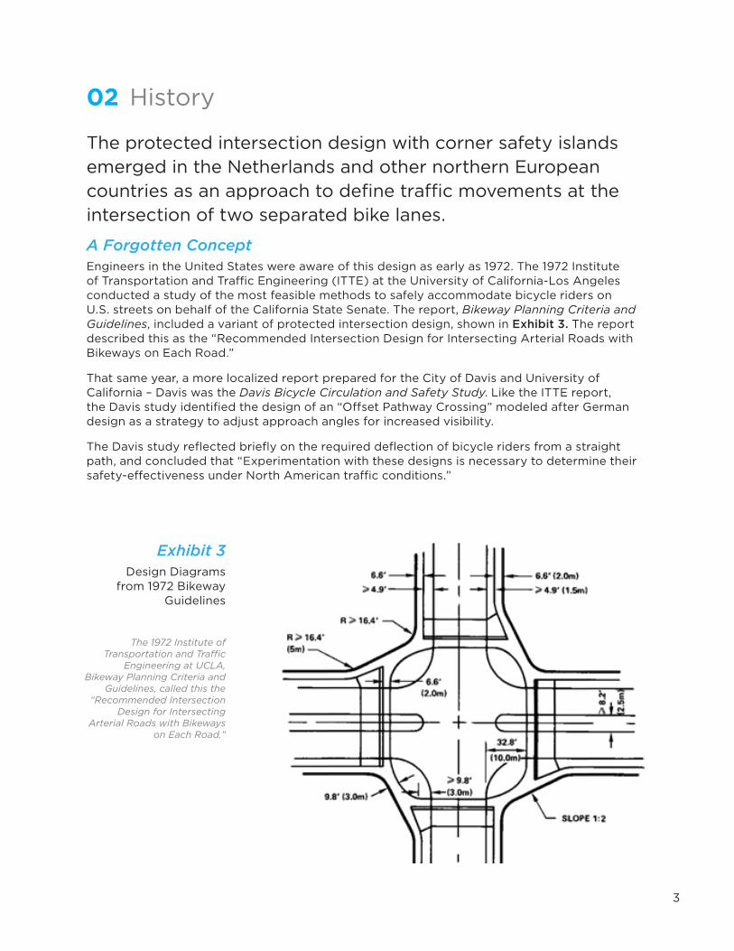
A Forgotten ConceptEngineers in the United States were aware of this design as early as 1972. The 1972 Institute of Transportation and Traffic Engineering (ITTE) at the University of California-Los Angeles conducted a study of the most feasible methods to safely accommodate bicycle riders on U.S. streets on behalf of the California State Senate. The report, Bikeway Planning Criteria and Guidelines, included a variant of protected intersection design, shown in Exhibit 3. The report described this as the “Recommended Intersection Design for Intersecting Arterial Roads with Bikeways on Each Road.”
That same year, a more localized report prepared for the City of Davis and University of California – Davis was the Davis Bicycle Circulation and Safety Study. Like the ITTE report, the Davis study identified the design of an “Offset Pathway Crossing” modeled after German design as a strategy to adjust approach angles for increased visibility.
The Davis study reflected briefly on the required deflection of bicycle riders from a straight path, and concluded that “Experimentation with these designs is necessary to determine their safety-effectiveness under North American traffic conditions.”
Exhibit 3Design Diagrams
from 1972 Bikeway Guidelines
The 1972 Institute of Transportation and Traffic
Engineering at UCLA, Bikeway Planning Criteria and
Guidelines, called this the “Recommended Intersection
Design for Intersecting Arterial Roads with Bikeways
on Each Road.”

4
Contemporary U.S. GuidanceContemporary bicycle facility design guidance does not address all of the protected intersection design features as elements for mitigating risk to bicyclists. The corner safety island and setback bicycle crossings are not directly featured in the AASHTO Guide for the Development of Bicycle Facilities or the NACTO Urban Bikeway Design Guide. The NACTO Urban Bikeway Design Guide does discuss the use of pedestrian safety islands in conjunction with separated bike lanes and the use of forward stop bars to shorten crossing distance with bicycle boulevards.
Some U.S. researchers and practitioners have noted these design elements in reviews of international best practices. Because of the limited application of separated bike lanes, some guidance was applied in the context of multi-use “sidepath” facilities.
The 1994 Florida DOT Trail Intersection Design Guidelines had a heavy emphasis on international practices and discussed the concept of setback crossings and slow turning speed:
It is important to control the speed of right turning vehicles, especially when the parallel roadway has a dedicated right turn lane or where there is a large turning radius which both tend to encourage high speed turns.
If a permissive left is in place, the trail should be setback 4 - 10 m (13 - 32 ft) from the roadway to allow motor vehicle stacking space.
Exhibit 4Diagram of separation
distance from a roadway near an
intersection
(Florida DOT, 1994)
Chapter 3. Design elements
Crossing types
3-6
Figure 10. Trail spacing near a roadway junction. (1m = 3.28 ft)
ParameterSeparation distance
<1-2 m 4-10 m >30 m
Motor vehicleturning speed
Lowest Higher Highest
Motor vehicle stacking space
None Yes Yes
Driver awareness oftrail user
Higher Lower High orLow
Trail user awarenessof motor vehicles
Higher Lower Highest
Chance of trail right-of-way priority
Higher Lower Lowest
(1m = 3.28 ft)
Table 3. Effects of trail-roadway separation distance.Separation distanceThe distance between the parallel roadway and trail (Figure 10)has a pronounced effect on operations. At issue is:
� turning motor vehicle approach speed to the trail;� stacking space between the parallel roadway and trail; � driver recognition of the trail; � trail user recognition of turning motor vehicles; and � trail right-of-way prioritization.
Table 3 shows the effects of separation distance on theseoperations parameters.
It is recommended that the separation distance categories—<1m to 2 m; 4 m to 10 m; or >30 m—in Table 3 be adhered to.They are a composite of the specifications from Finland andThe Netherlands as shown in Figure 10. Note that thesecategories are exclusionary.In 2008, researchers John Pucher and Ralph Buehler published Making Cycling Irresistible:
Lessons from The Netherlands, Denmark, and Germany and noted key geometric design features used in northern European counties to create comfortable conditions for bicyclists. On the topic of intersection modifications, the authors write:
[The intersection designs] generally include many of the following:• Special bike lanes leading up the intersection, with advance stop lines for
cyclists, far ahead of waiting cars;• Insertion of traffic islands and bollards in roadway to sharpen turning radius
of cars and thus force them to slow down when turning right; and• Realigning bike pathways a bit further away from their parallel streets when
they approach intersections to help avoid collisions with right-turning cars.
5
111
CHAPTER 5 | MENU OF DESIGN RECOMMENDATIONS
• A ‘Turning vehicles yield to bikes’ sign may be placed on the mast arm.
• For further guidance on typical signs and markings for separated bike lanes, see page 127.
• For further guidance on signal phasing, see page 119.
TURNING MOVEMENTS
Bend-Out
• Bend-out design provides opportunity for an ample pedestrian refuge between the separated bike lane crossing and the roadway crossing.
• Separated bike lane and crosswalk may be raised to sidewalk level through the intersection, providing a traffic calming effect.
• For further guidance on buffer selection and installation, see page 83.
The bend-out design positions bicyclists downstream on the side street away from the intersection, allowing vehicles to complete turning movements before interacting with bicyclists. This design, which could be used on lower-volume side streets or driveways, provides space for a vehicle to yield to crossing bicycles without blocking through traffic on the main street. A Bicycle/Pedestrian Warning (W11-15) sign may be used as driveways approach separated bike lanes to alert drivers to be aware for bikes and pedestrians.
05
0401
02
03
NOT TO SCALE
Figure 26
06
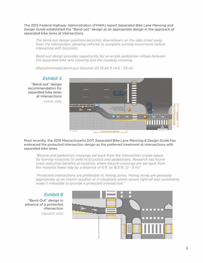
The 2015 Federal Highway Administration (FHWA) report Separated Bike Lane Planning and Design Guide established the “Bend-out” design as an appropriate design in the approach of separated bike lanes at intersections.
The bend-out design positions bicyclists downstream on the side street awayfrom the intersection, allowing vehicles to complete turning movements beforeinteracting with bicyclists.
Bend-out design provides opportunity for an ample pedestrian refuge between the separated bike lane crossing and the roadway crossing.
[Recommended bend-out distance of] 15-25 ft (4.5 - 7.5 m)
Most recently, the 2015 Massachusetts DOT Separated Bike Lane Planning & Design Guide has embraced the protected intersection design as the preferred treatment at intersections with separated bike lanes.
“Bicycle and pedestrian crossings set back from the intersection create space for turning motorists to yield to bicyclists and pedestrians. Research has found crash reduction benefits at locations where bicycle crossings are set back from the motorist travel way by a distance of 6 ft. to 16.5 ft. (2 - 5 m)”
“Protected intersections are preferable to mixing zones. Mixing zones are generally appropriate as an interim solution or in situations where severe right-of-way constraints make it infeasible to provide a protected intersection.”
Exhibit 5“Bend-out” design
recommendation for separated bike lanes
at intersections(FHWA, 2015)
Exhibit 6“Bend-Out” design in
advance of a protected intersection
(MassDOT, 2015)

6
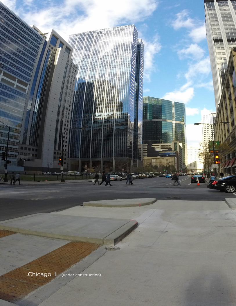
Chicago, IL (under construction)

7
03 Planning and PolicyConventional bike lanes, shared roadways, or bicycle boulevards can be brought into the protected intersection design by transitioning the bikeway into short separated bike lane segments upstream of the intersection. The protected intersection design is applicable at both signalized and stop controlled intersections.
Planning Level Space RequirementsTo achieve the desired setback crossing design, protected intersections may require more space in the immediate vicinity of the intersection than intersections with conventional facilities. This space requirement is dictated by a number of factors, including lane configuration, presence of parking, and turning radius requirements.
When designing a protected intersection, roadside dimensions and intersection right-of-way are more of a controlling factor than total roadway width. Exhibit 7 illustrates the roadside space and/or corner right-of-way is necessary to implement corner safety islands and offer maneuverability, queuing storage, and separation between modes.
Exhibit 7Roadside
right-of-way
Narrow roadside environments may
require additional right-of-way at corners in
order to meet preferred design dimensions of a protected intersection.
Wide Roadside Narrow Roadside
Wide roadside environment offer ample room to position safety islands and set back the bicycle and pedestrian crossings within the right-of-way limits.
Narrow roadside environments with minimum dimension sidewalks and separated bike lanes offer little extra space for maneuvering or queuing within the right-of-way. Acquisition of additional right-of-way at corners may be necessary.

8
Policy Considerations Large Vehicle Accommodation PolicyA key design feature in protected intersections is geometry designed to slow driver turning speeds. This geometry may be incompatible with some classes of large vehicle movements. Truck accommodation and design compatibility issues may be addressed through a nuanced truck accommodation policy including different classes of truck networks and design vehicles (ITE, 2011).
See Section 06, Large Vehicle Accommodation, for more discussion on design strategies.
Layered NetworksThe layered network approach to truck accommodation can encourage large trucks on certain routes but not others. On high-priority bicycle routes, it may be appropriate to provide an alternate route for large vehicles to prevent or minimize intermodal conflicts. Prohibiting turning for some large vehicles may also be an option where it cannot be safely accommodated.
Design and Control VehiclesThe NACTO Urban Street Design Guide (NACTO, 2013) offers guidance on the challenges of “designing for” large vehicles versus “accommodating [large vehicles] as an infrequent user”. Curb radii designed to accommodate the largest possible vehicle will result in significant compromises in protected intersection design. If turning is allowed, drivers of large vehicles are trained to take unconventional paths through intersections when needed.
Non-Compliant Signalization PhasingFHWA Interim Approval 16 (IA-16) identifies national direction on bicycle signal installation and identifies key restrictions on their use. These restrictions include:
• Bicycle signal faces may not be used concurrently with conflicting vehicular phases. This restricts bicycle signals from being used as a leading phase; however pedestrian signals allow this.
• IA-16 prohibits bicycle scramble phases. It is unclear if this would apply to a protected intersection as bicyclist mixing would happen prior to entering the intersection. A scramble phase for bicyclists in the context of a protected intersection has more similarity to circulation through a roundabout than an an open intersection with many possible paths of travel.
See Section 07, Signal Phasing, for more discussion on signalization approaches and IA-16 compliance.

9
Right Turn on RedThere is no current research or consensus on whether right turns on red should be prohibited in protected intersection designs. The greater distance a right-turning vehicle would have to travel to enter the traffic stream on the cross street may make restrictions a prudent design decision. The presence or lack of dedicated right turn lanes may also influence this decision, as will the number of turning vehicles that is to be accommodated.
See Section 07, Signal Phasing, for more discussion on right turn on red.
Accessibility ImplicationsThe application of the protected intersection design does have pedestrian accessibility considerations. In the scenario of introducing a separated bike lane “traveled way,” it could be interpreted that detectable warnings would be needed to define the edge of this traveled way. This scenario is not unlike a free right lane for cars where pedestrians have priority. Alternatively, the City of Davis, California, has chosen to make the corner areas a shared bicycle/pedestrian area through the application of shared-use paths rather than exclusive separated bike lanes and parallel pedestrian sidewalks. These strategies may have implications on the minimum allowable pedestrian signal phase. Additional issues with these two approaches include:
• Location of the pedestrian push button (if signal does not rest on recall) within the pedestrian refuge island versus behind the separated bike lane. This decision may have implications for minimum calculated crossing timing. One possible advantage of a protected intersection is the potential for lowering the necessary pedestrian crossing timing versus a wider intersection. This could result in the option of shorter cycle lengths, or less delay for all users.
• Whether bicyclists and pedestrians are separated in their respective waiting areas with a physical barrier.

10
Salt Lake City, UT

11
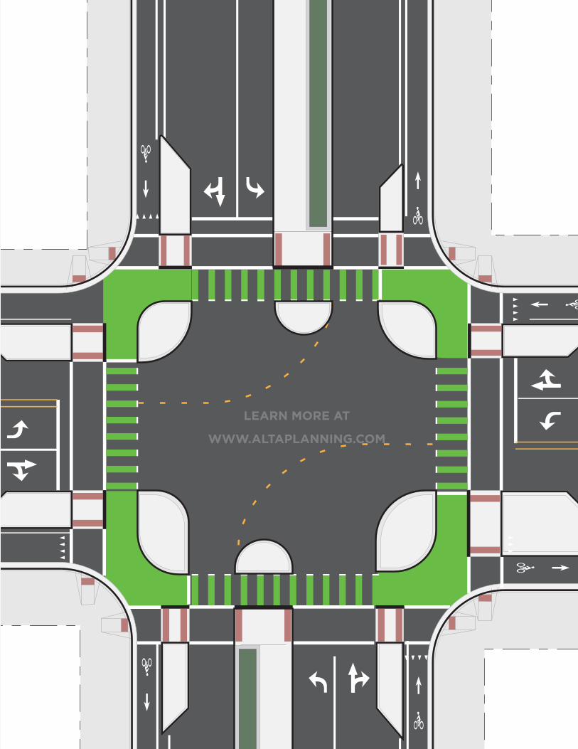
04 Elements of a Protected Intersection Protected intersections use a variety of design elements to create safe, comfortable conditions for bicyclists, illustrated in Exhibit 8. While not all of these elements are required in all situations, they make up the typical protected intersection experience.
Exhibit 8Visual illustration of key protected
intersection features
Corner safety islands have multiple roles: offering
a protected place for bicyclists to queue when
crossing and turning, and managing the speed of
turning vehicles when permitted turn conflicts are
allowed.
Special attention should be paid to the amount of
deflection required for both pedestrians and bicyclists in advance of the intersection.
Corner Safety Island
Corner Apron
Forward Stop Bar
Yield to Pedestrians
Setback Bicycle Crossing
Approach Taper
Pedestrian Safety Island
Signal Operations

12
Exhibit 9Description of key protected
intersection features
Feature Description
Corner Safety Island A corner safety island is a raised area that separates the separated bike lane from the general purpose travel lane and defines the corner radius of the intersection. The island provides comfort for waiting bicyclists and may manage the speed of turning vehicles.
Corner Apron A corner apron is an optional traversable part of the corner safety island that may be needed to accommodate the wheel tracking of large vehicles.
Forward Stop Bar The forward stop bar marks the location at which bicyclists are intended to stop and wait at a red signal indication.
Approach Taper The separated bike lane may shift in advance of the intersection to align bicyclists with the setback bicycle crossing. This taper should be subtle to minimize impacts to bicyclists.
Yield for Pedestrians Bicyclists should yield to crossing pedestrians at the location of pedestrian crosswalks prior to progressing to the forward stop bar. Yield line markings and signs should identify this requirement.
Pedestrian Safety Island
The pedestrian safety island is installed between the separated bike lane and general purpose travel lanes, allowing pedestrians to queue on a DON’T WALK signal and shorten crossing distance of the roadway.
Setback Bicycle Crossing
To improve sightlines and clearly establish priority, the bicycle and pedestrian crossings are set back from that of the adjacent through travel lanes.
Bicycle Signal Optimization
Various signal phasing schemes may be used in combination with geometric design to mitigate or prevent conflict between bicyclists, pedestrians, and turning motor vehicles.

13
Exhibit 10Summary of benefits and
challenges
Benefits ChallengesPedestrians
Shortened roadway crossing distance.
Reliance on bicyclists yielding to pedestrians with right of way.
Slower driver speed reduce collision severity and increases yielding to crossing pedestrians.
SafetyProvide more reaction time for all users to detect and correct for mistakes due to lower vehicle speed.
May increase difficulties for individuals with vision disabilities due to the potential for pedestrian path deflection and challenges in detecting adjacent moving bicyclists.
OperationsShorter bicycle and pedestrian crossing distance created by the forward stop bar and pedestrian safety island allow these users to clear the intersection in less time.
If right-turn-on red is prohibited, it may negatively impact capacity.
If exclusive bicycle signal phase or leading pedestrian/bicycle intervals are used, may negatively impact intersection capacity.
SpaceMay not require additional right-of-way on streets configured with on-street parking and wide sidewalks.
Many intersections could be reconfigured to be protected intersections within the existing footprint.
Certain signal phasing schemes may require an exclusive left and right turn lane, potentially increasing the physical size of the intersection.
Achieving the desired crossing setback distance from the roadway may require right-of-way acquisition at corner locations.
MaintenanceMay require specialized sweeping and snow removal (if applicable) practices to keep clear of snow and debris.
AestheticsPedestrian safety islands offer an opportunity for low level landscaping, or placemaking elements such as art or lighting.
Results in a cleaner looking intersection when compared to other intersection treatments such as mixing zones or bike boxes.

14
Austin, TX

15
05 Geometric DesignDesign elements are common to most configurations, although details differ depending on the bikeway type, lane configuration, and intersection signal phasing.
Exhibit 11Basic geometric
elements and key dimensions of a
Protected Intersection
Corner Radius20 ft or greater based on control vehicle
Crossing Setback19.5 ft preferred if if con�icting turning move-ments are allowed
Approach TaperFor smooth transition to setback crossing
10 ft min.
BicycleQueuing8 x 6.5 ft Preferred
Apron Radius(If applicable10-20 ft based on passenger car turning speed
Pedestrian Island6.5 - 14 ft

16
Setback CrossingIf permissive turns are allowed across the separated bike lane, it is important to provide adequate setback area to encourage maximum visibility, proper motor vehicle yielding, and efficient operation.
U.S. guidelines for setback crossings in roundabouts identify 19.5 feet (6 m), about one car length, as the preferred setback distance for yielding prior to crosswalks (NCHRP, 2010). This is supported in U.S. federal separated bike lane guidelines with a recommend 15- to 25-foot (4.5 to 7.5 m) setback distance in advance for intersections (FHWA, 2015). 2006 Dutch guidelines on setback bicycle crossings call for 13 to 23 feet (4 to 7 m) depending on context and physical constraints (CROW, 2006). More recent Dutch research identifies 16.4 feet as the preferred setback distance, with 6.5 feet (2 m) identified as a constrained minimum (Fietsberaad, 2011).
Setback distances should be selected in conjunction with corner radius dimensions to encourage slow speeds and proper vehicle alignment at the crossing. The angle of approach at the bikeway crossing should be as close to 90 degrees as possible (minimum 70 degrees, AASHTO, 2011).
Inadequate setback distances may lead to blockage of the separated bike lane by vehicles turning right-on-red or blockage of the through travel lane by vehicles yielding to crossing bicyclists. Lane blockage may not be a concern if right-on-red is prohibited and turning movements are protected through signalization.
Exhibit 12Setback bicycle and pedestrian crossings
A setback of 19.5 ft (6 m)provides enough room for one passenger car to yield
to bicyclists and pedestrians, while waiting outside of
the flow of through motor vehicle traffic.
Crossing Setback19.5 ft (6.0 m)
Exhibit 13Narrow setbacks offer
insufficient storage and sight lines
Small crossing setbacks may lead to blockage of
the protected bike lane or through travel lane.

17
Corner Safety IslandThe corner safety island offers comfort for bicyclists waiting at the intersection, improves visibility of bicyclists to turning drivers, shortens overall crossing distance, and may be used to enforce a specific motor vehicle turning speed.
Dimensions of the corner safety island may impact large vehicle accommodation through the intersection and bicyclist queuing capacity. See Section 05, Large Vehicle Accommodation.
Turning speed should be limited to 15 mph or less when permissive right turns across the path of through bicycles are allowed. Minimizing turning speeds is important for pedestrian and bicyclist safety (Fitzpatrick, 2005). Turning speed can be influenced by corner radius, as described in Exhibit 14.
In roundabouts, an intersection type with similar setback crossing geometry, researchers have shown that speed has a significant influence over motorist yielding rates, illustrated in Exhibit 15.
The AASHTO A Policy on Geometric Design of Highways and Streets discusses the preference for low turning speeds at most intersections:
... vehicles turning at intersections designed for minimum-radius turns have to operate at low speed, perhaps less than 15 km/h [10 mph]...it is often appropriate for safety and economy to use lower turning speeds at most intersections. (AASHTO, 2011, pages 3-57)
Exhibit 14Horizontal curve
speed and radius reference chart
(AASHTO, 2011, Equation 3-8)
Exhibit 15Driver travel speed and yielding rates
at roundabout crosswalks.
(Geruschat, 2005)
252015105
0
50
100
Speed (MPH)
Per
cent
Yie
ld
V (mph) E F* R (ft)8 0 0.38 11
10 0 0.38 18
12 0 0.35 27
15 0 0.32 47
Values from AASHTO Green Book 2011, Table 3-7 and Equation 3-8
The formula for calculating turning speed is R = V2/15(.01E + F) where:R is the turning radius (effective) V is speed in miles per hour (mph) E is super-elevation. This is assumed to be zero in urban conditions. F is side friction factor

18
Forward Stop BarThe inside radius of the corner safety island may impact bicyclist maneuverability and left turn storage capacity. Maximize the inside radius to allow for smooth transition into the queue area and to maximize capacity. In the transition area behind the corner safety island areas, provide a minimum of 10 feet (3.0 m) of space between the corner safety island and pedestrian sidewalk.
The bicycle stop bar should be clearly marked to identify where bicyclists should wait at a red signal indication or stop sign. The FHWA Separated Bike Lane Planning and Design Guide (FHWA, 2015) provides minimum dimensions of a two-stage turn queue box as 10 feet by 6.5 feet (3.0 m by 2.0 m) deep. This may be unachievable and is potentially undesirable to have a 10 foot (3.0 m) bike lane gap which may result in use by motor-vehicles. It is particularly important to clarify the stop location in areas where a corner apron is used to make sure users are waiting outside of the potential path of large vehicles.
Exhibit 16Bicyclist queuing
and transition at the forward stop bar
10 ft min(3.0 m)
Bicyclist queue areaInside radius

19
Pedestrian Safety IslandThe pedestrian safety island should follow standard practices for conventional median safety islands (AASHTO, 2011).
The raised median or crossing island must be at least 4 feet (1.2 m) wide and 6 feet (1.8 m) long to serve adequately as a refuge area for pedestrians, in accordance with Manual on Uniform Traffic Control Devices (MUTCD) and American Association of State Highway and Transportation Officials (AASHTO, 2004) guidelines.
Detectable warnings are required where users are expected to wait and to identify the point of transition to the roadway. It is particularly important to clarify the wait location in areas where a corner apron is used to indicate to users where to wait outside of the potential path of large vehicles.
Safety islands in intersection can confuse pedestrians with vision impairments and slow or delay their crossing. Care should be taken to minimize any change of direction at the safety island locations (NCHRP, 2007).
Exhibit 17Pedestrian safety
island in New York, NY
This pedestrian safety island simplifies
pedestrian crossings into two stages and
physically separates the protected bike lane from
moving motor vehicles.

20
Exhibit 18Configuration with
mixed-traffic bicycle boulevard
Integration with Other BikewaysConfiguration with Mixed-Traffic Bicycle BoulevardsIn some locations, separated bike lanes will cross bicycle boulevards. In these conditions, the bikeway may transition into a separated bike lane in advance of the intersection.
Design Considerations
• Use clear markings and signs to direct users into the separated bike lane portion of the intersection.
• The entrance to the protected intersection should be located to avoid obstruction by parked cars.
• The exit to the bicycle boulevard should be positioned to maximize visibility of bicyclists as they enter the traffic stream.
Crossing Setback
Mixed tra�c to separated bike lane transition

21
Exhibit 19Configuration with
on-street bike lanes
Configuration with Conventional Bicycle LanesIn some locations, separated bike lanes will cross conventional on-street bike lanes, and designers may use the protected intersection design to connect the two facilities. In these conditions, one potential configuration is to transition the bicycle lane into a separated bike lane in advance of the intersection. This allows users on both facilities to benefit from the safety islands and easily connect to the other route.
Design Considerations
• Transitions from conventional bicycle lanes should start far in advance of the intersection in order to provide a gentle taper of 1:10 (1:5 minimum). Short tapers may be considered uncomfortable, and safety islands may appear as obstructions in the roadway to be avoided.
• Standard separated bike lane widths should be used in the separated bike lane segment.
Crossing Setback
Taper transition from bike lane

22
Exhibit 20Configuration with
intersections of one- and two-way
protected bike lanes
Configuration with One- and Two-Way Separated Bike LanesWhere a one-way separated bike lane intersects a two-way separated bike lane, protected intersection principles can provide legibility to circulation and wayfinding.
Design Considerations
• A different range of maneuvers occur at intersections with two-way facilities. Consider all potential movements from one bikeway to another, and provide rounded corners and widened transition areas to allow for these movements.
• Provide a queuing space so that waiting bicyclists are not interfering with the movement of through traveling bicyclists. The forward stop area should be designed to maximize capacity and minimize bicycle overhang.
Rounded corners for all potential bicycle movements

23
20 ft (3.0 m) preferred for all direction travel
Exhibit 21Configuration with two-way protected
bike lanes
Configuration with Two-Way Separated Bike Lanes Protected intersection design elements may also function well to improve comfort and safety of two-way separated bike lanes.
Design Considerations
• Queuing space and maneuverability becomes a key concern when configured at the intersection of two-way separated bike lanes, as more users pass through the same physically-constrained location.
• Intersections of two-way separated bike lanes may see large volumes of users. Increased separation from the roadway may provide additional storage capacity, and short signal cycle lengths may help clear the bicycle queuing area more frequently.
• Because of the potential for increased levels of conflicts with two-way separated bike lanes, permissive conflicts between motor vehicles and bicyclists should be prohibited at signalized intersections along two-way cycle tracks.
24
Chicago, IL (under construction)

25
06 Large Vehicle AccommodationWhen the corner safety island is used to manage permissive turns, the protected intersection designer should pursue all available strategies to minimize the corner radius necessary for vehicle accommodation.
Turning RadiusThe design of a corner safety island should be based on an understanding of the intersection design vehicle and control vehicle in order to create the key dimensions necessary to accommodate the right turns through the intersection. These concepts are illustrated in Exhibit 22.
The design vehicle is a frequent user of a given street and dictates the minimum required turning radius.
The control vehicle is an infrequent large user of the intersection. The designer should provide operational accommodation of the control vehicle, assuming the operator will use adjacent and opposing lanes when beginning and completing a right turn. The designer should understand the minimum radius necessary to permit the control vehicle to successfully navigate the intersection.
Exhibit 22Difference in corner
radius design for Design Vehicle and
Control Vehicle
(Adapted from: City of Portland. Street Design
Guidelines for Trucks. 2006)
Sizing the corner radius for the design vehicle (right) permits
direct travel from exiting lane into the receiving lane without tracking
into adjacent lanes.
Sizing the radius for the control vehicle (left) assumes the operator
will utilize adjacent and opposing lanes as necessary to complete
the turn.
Minimize turning radiusStrategies listed in the NACTO Urban Street Design Guide include:
• Select the smallest possible design vehicle
• Accommodate trucks and buses on designated truck and bus routes
• Restrict right-turns-on-red so there is no expectation of turning into the nearest receiving lane
• Set back the stop bar of inside travel and turn lanes to provide additional maneuverability
• Design so that emergency vehicles may utilize the full area of the intersection for making turns

26
Exhibit 24Corner apron
installed in channelized turn lane in Bend, OR
(Image: Google Streetview)
Exhibit 23Designing for large
vehicle turns and slow passenger car
turning speeds
The corner apron is visually distinct from
both the roadway and the sidewalk.
By using a mountable corner apron the design
can successfully allow necessary navigation of the intersection of
large vehicles while still managing the turning
speed of passenger vehicles.
Mountable curb radius:10-20 ft(3 -6 m)
Barrier curb radius: 30 ft (9 m) or greater
Provisions for Wide Corner RadiiIf design and control vehicle accommodation requires a large corner radius, passenger cars may be able to turn at a high rate of speed. Because vehicle speed has implications with yielding compliance and crash severity, a wide corner radius is undesirable if permissive turns are allowed across the separated bike lane.
If a wide corner radius is unavoidable, a mountable corner apron should be used to define a secondary corner radius designed to promote a passenger car turning speed of 5 to 10 mph.
Corner aprons should be designed as visually distinct from both the roadway and the corner safety island. A textured surface on the apron may further discourage passenger cars from using the apron to make fast and wide turns.
27
07 Signal Operations
Signalization, lane configuration, and user volumes all have an effect on intersection throughput, delay, and safety. All intersections are unique, and the approaches presented here will need to be adapted to local conditions. Designers should evaluate scenarios to understand the optimal configuration and phasing strategy. Conventional intersection modeling tools such as Synchro do not take into account all elements of the intersection design and do not model bicyclist behavior or right turn yielding within the set back crossing area.
Microscopic modeling tools such as PTV Vissim may be used to model the complexities of the protected intersection geometry.
Overview of Signal Phasing ApproachesThe following pages include a high-level discussion of various signal phases compatible with protected intersection geometric design.
Each intersection requires additional review by a registered engineer to identify sight lines, potential impacts on traffic progression, timing with adjacent signals, capacity, and safety.
Discussion includes:
• Protected but Concurrent Phasing
• Protected Left Turn Phasing
• Permissive-Only Phasing
• Exclusive All-Way Green Bicycle/Pedestrian Phasing
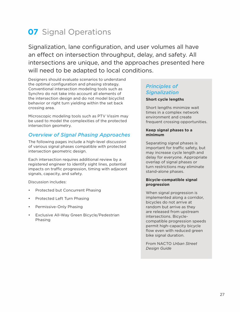
Principles of SignalizationShort cycle lengths
Short lengths minimize wait times in a complex network environment and create frequent crossing opportunities.
Keep signal phases to a minimum
Separating signal phases is important for traffic safety, but may increase cycle length and delay for everyone. Appropriate overlap of signal phases or turn restrictions may eliminate stand-alone phases.
Bicycle-compatible signal progression
When signal progression is implemented along a corridor, bicycles do not arrive at random but arrive as they are released from upstream intersections. Bicycle- compatible progression speeds permit high-capacity bicycle flow even with reduced green bike signal duration.
From NACTO Urban Street Design Guide

28
Protected but Concurrent Phasing Under this phasing scheme, both right turns and left turns have their own signal phase separate from through movements. The bicycle and pedestrian crossing runs at a different time from the conflicting turn phase, yet concurrent with the vehicular through phase. This offers the comfort of a protected signal phase, while still moving non-conflicting motor vehicles.
Exhibit 25Intersection with
protected but concurrent phasing
This phasing scheme requires dedicated turn
lanes or turn prohibitions for all conflicting
movements.
The corner safety island is not used to manage
turning speed, but instead provide comfort for
waiting bicyclists.
In this configuration, corner radius may be
enlarged and crossing set back distance may be
reduced.
OLB
OLA
OLC
OLDΦ5 Φ1 Φ2
Φ4
Φ8 Φ8P/B
Φ4P/B
Φ6
Φ7
Φ3
Φ6B/P
Φ2B/P Vehicle Movement
Permissive Turn Movement
Bicycle/Pedestrian Movement(Pedestrians move in two direcions)

29
Typical Application• Intersections where dedicated turn lanes are provided for all conflicting movements
• Intersections where conflicting turn movements are prohibited
• Intersections with relatively low numbers of turning vehicles
• Intersections where exclusive pedestrian/bicycle-only phase would introduce too much delay
Benefits and Considerations• Consider the reduced crossing distance provided by the pedestrian safety islands when
calculating signal timing needs. In large intersections, this may lead to overall time savings when compared to conventional designs.
• Because protected signal phasing depends on signalization-control to eliminate conflicts, right-turn-on red should be prohibited.
• Because of the added space requirements of dedicated turn lanes, the bicycle and pedestrian crossing may need to be set back farther than with an outside shared through/right lane.
• Consider the needs of pedestrians with vision disabilities. The surge of traffic by right-turning vehicles using a protected right-turn phase may be incorrectly interpreted as the beginning of the parallel through traffic surge and the simultaneous onset of the WALK interval. Provide an Accessible Pedestrian Signal (APS) to provide guidance for these users (NCHRP, 2007).
Configuration Needs
• This design requires exclusive left- and right-turn lanes. These movements should be prohibited if they cannot be protected.
• Bicyclists are required to make a left turn in two stages. Adequate room should be provided for bicyclist queuing at the forward stop bar.
• Because corner safety islands are not used for speed management, they may be designed with a larger corner radius than would otherwise be desirable.
Capacity/Delay ImplicationsLeft- and right-turn flows should be similar and proportionally low for this configuration to function well. It is likely that this configuration would have relatively higher delay for some movements than others in this section.
FHWA IA-16 Bicycle Signal Face ComplianceProtected-but-concurrent signal phasing can be implemented in compliance with FHWA IA-16 at this time.
Right-turn-on-red must be prohibited to comply with IA-16 condition 3c.

30
Protected Left Turn PhasingThis signal phasing approach offers protected left turn movements but allows permissive right turns to occur concurrently with conflicting bicycle and pedestrian through movements. This configuration is common practice today, with the underlying assumption that a motorist or bicyclist making a turn must yield to pedestrians and bicyclists.
Exhibit 26Intersection with
protected left turn phasing
This phasing scheme permits a shared
through/right lane to travel at the same time
as through bicyclists.Because permitted
right turn conflicts are allowed, the corner
safety island must be carefully designed to
slow driver turning speed.
Φ5 Φ1 Φ2Φ8 Φ8P/B
Φ4Φ4P/BΦ6
Φ7
Φ3
Φ6B/P
Φ2B/PVehicle Movement
Permissive Turn Movement
Bicycle/Pedestrian Movement(Pedestrians move in two direcions)

31
Typical Application
• Where right-turning traffic is light to moderate and sight distance is adequate.
• Where there is limited physical space or capacity for exclusive right turn lanes and signal phases.
• There is no national standard for when permissive conflicts between right-turning vehicles and pedestrians or bicyclists is considered acceptable. The general rule is that, as long as the geometry forces right turns to be made at low speed and the right turn volume is acceptably small, permissive conflicts may be allowed. Because of the increased speed at which bicyclists operate compared to pedestrians, these considerations are even more critical.
Configuration NeedsCorner safety islands should utilize a small corner radius to encourage slow driver turning speeds. If large vehicle accommodation requires a large turning radius, use a mountable corner apron to define a smaller radius to control passenger car speed.
Capacity/Delay ImplicationsThis scenario was found to achieve the lowest overall delay (unless large numbers of bicyclists and pedestrians were present) by a recent study and had substantial performance improvements over a conventional intersection design (Stanek, 2015).
FHWA IA-16 Bicycle Signal Face CompliancePermissive right turn phasing using a standard green ball indication for both bicyclists and motor vehicles is compliant with FHWA Interim Approval 16.
Permissive conflicts in conjunction with a green bicycle signal face is prohibited by IA-16 per condition 3c. The approval restricts the use of green bicycle signals indications to conditions where “the bicyclists are not in conflict with any simultaneous motor vehicle movements at the signalized location.”
Leading Pedestrian/Bicycle IntervalThis phasing strategy is compatible with a leading interval, which would give both pedestrians and bicyclists a short “head start.” The forward stop bar and pedestrian refuge elements of the protected intersection already provide a physical leading interval by positioning these vulnerable users as much as 30 feet (10 m) in advance of parallel vehicles. If an additional signal leading interval is desired, it is likely that most queued bicyclists or pedestrians will have cleared the intersection before the arrival of vehicles. IA-16 does not allow leading bicycle signals. It is possible that a legal bicycle leading interval could be achieved through the use of the pedestrian signal combined with a R9-5 “Bicycles Use Ped Signal” sign.
Visually-impaired pedestrians will typically assume that the WALK interval will begin with the onset of through traffic on the parallel street. Use of an Accessible Pedestrian Signal (APS) is necessary to inform these uses of the appropriate time to cross the street in these conditions.

32
Permissive-Only Signal PhasingPermissive-only operation requires both left- and right-turning drivers to yield to conflicting vehicle, bicycle, and pedestrian traffic streams before completing the turn.
While separated turn lanes may be provided, the left- and right-turn movements are presented with a circular green indication and travel concurrently with the through movement
Exhibit 27Permissive-only
phasing
This phasing scheme permits all movements in one direction pair to travel at once. Turning
motor vehicles must yield to conflicting vehicle,
bicycle, and pedestrian traffic.
Because permitted right turn conflicts are allowed,
the corner safety island must be carefully
designed to slow driver turning speed.
Φ1
Φ6Φ4 Φ7
Φ8Φ3
Φ6B/P
Φ2B/P
Φ5
Φ2 Φ8P/B
Φ4P/B
Vehicle Movement
Permissive Turn Movement
Bicycle/Pedestrian Movement(Pedestrians move in two direcions)

33
Typical Application• Where turning traffic is light to moderate and sight distance is adequate.
• Where there is limited physical space or capacity for separated turn lanes and signal phases.
Configuration Needs• Turn lanes may be provided, but protected green arrow indications are not used. Flashing
yellow arrows should be used to highlight the need to yield to through traffic.
• Corner safety islands should use a small corner radius to encourage slow driver turning speeds. If large vehicle accommodation requires a large turning radius, use a mountable corner apron to define a smaller radius to control passenger car speed.
Capacity ImplicationsPermissive-only operation provides the most efficient operation for green allocation at the intersection under low turning volume scenarios. The efficiency of this mode is dependent on the availability of gaps in the conflicting streams through which the turn can be safely completed.
This configuration can have an adverse effect on safety in some situations, such as when the left-turn driver’s view of conflicting traffic is restricted or when adequate gaps in traffic are not present.
FHWA IA-16 Bicycle Signal Face CompliancePermissive-only phasing as described here using a circular green indication for both bicyclists and motor vehicles is compliant with the MUTCD.
FHWA Interim Approval 16 condition 3c restricts the use of green bicycle signals indications to conditions where “the bicyclists are not in conflict with any simultaneous motor vehicle movements at the signalized location.”

34
Exclusive All-Way Bicycle/Pedestrian PhasingAll-way bicycle and pedestrian phase offers an exclusive phase for non-motorized users in all directions at once. Permissive conflicts between bicyclists and pedestrians are negotiated between users.
Exhibit 28Exclusive all-way
green bicycle/ pedestrian phase
Under all-way green signal timing, all
bicycle and pedestrian movements in all
directions travel at the same time.
Because of the timing impacts of the exclusive
bicycle/pedestrian phase, it may be most
appropriate on a lower volume street with simple two-phase
permissive-only phasing for the motor vehicle
travel lanes.
Φ8P/B
Φ4P/BΦ1Φ6
Φ4 Φ7
Φ8Φ3
Φ6B/P
Φ2B/P
Φ5Φ2 Φ8P/B
Φ4P/BΦ6B/P
Φ2B/P
Vehicle Movement
Permissive Turn Movement
Bicycle/Pedestrian Movement(Pedestrians move in two direcions)

35
Typical Application• At intersections with high volumes of bicyclists in multiple directions.
• At simple intersections in constrained right-of-way where separate turn lanes are not possible.
• At intersections where protected turn phases are not desirable.
• At intersections with relative low motor vehicle traffic volumes.
Benefits and Considerations• Compared to a non-protected crossing, the protected phasing creates extra delay for
bicyclists and other users (ITE, 2013).
• This method offers signalized protection for bicyclist and pedestrian movements at intersections without separated turn lanes.
• With sufficient phase length, bicyclists are able to turn left in one movement.
Configuration Needs• Simple intersections without turn lanes or turn signals.
• The ability for this design to protect users relies on user compliance of traffic signals. Right-on-red must be prohibited to ensure the safety of the all-way bicycle phase.
Delay ImplicationsThe introduction of exclusive bicycle/pedestrian phases will decrease capacity proportional to the added duration of the exclusive bicycle/pedestrian phase.
Bicycle DelayIf delay between bicycle/pedestrian-only phases is too long, bicyclists may be tempted to travel with the adjacent green signal. To encourage compliance, recall the simultaneous green phase twice per cycle in order to increase service for bicyclists and pedestrians. Because delay is a function of the length of red periods, giving bikes two short green periods is far more advantageous than giving them a single longer period.
FHWA IA-16 Bicycle Signal Face ComplianceAs described here, the simultaneous green signal phasing is prohibited by FHWA Interim Approval 16 per condition 8c.
The approval restricts the use of bicycle signals to fully protected conditions only and prohibits use that “allow multiple bicycle movements from multiple conflicting directions.” Because the protected intersection design uses corner safety islands, it could be argued that bicyclists would not be in a “scramble” as they would be moving through the intersection with operations similar to a roundabout.

36
Additional Signalization ConsiderationsLeading Bicycle IntervalOne potential method to mitigate the risk of permissive conflict conditions is to provide a Leading Bicycle Interval (LBI). An LBI is a brief bicycle/pedestrian-only phase that starts a few seconds before the adjacent through movement phase. This allows non-motorized users to establish a presence in the crossing area prior to the arrival of turning vehicles. Turning vehicles must yield to crossing users before proceeding through. Currently, the leading bicycle interval is non-compliant with FHWA IA-16 regulating the use of bicycle signal heads.
Leading pedestrian intervals support improved safety for pedestrians by allowing them increased visibility within the intersection and is applicable to intersections where there are significant pedestrian-vehicle conflicts (Lalani, 2001).
Right Turn on RedRight turn on red has been shown to increase collisions involving pedestrians and bicyclists (NHTS, 1981), and a signficant number of drivers performing right turn on red fail to yield to pedestrians (Wagoner, 1992).
While the law requires motorists to come to a full stop and yield to cross-street traffic and pedestrians prior to turning right on red, many motorists do not fully comply with the regulations. Noncompliance is particularly common at intersections with wide turning radii.
Motorists are often so intent on looking for gaps in traffic that they may not be alert to crossing pedestrians or bicyclists. In addition, motorists usually pull close to the crossing travel lanes to improve visibility and wait for a gap in traffic. This may block pedestrian and bicycle crossing movement and minimize the benefits of a forward stop bar or leading bicycle interval.
The decision to provide for right turn on red in protected intersection designs should be made by a registered traffic engineer after evaluation of safety. Consideration should be given to the likelihood of increased pedestrian/bicyclist/driver conflicts at the start of a green light, and the potential for automobiles to block the path of through bicyclists.

37
08 Case StudiesAs of December 2015, there are four installations of protected intersections in the United States and two in Canada. Traffic conditions, land use context, and geometric design vary widely between each installation, but, in each case, protected intersection principles are applied to increase comfort, safety, and clarity for people riding bikes. The following pages include design details, illustrations, and photographs of the six designs in North America.
Salt Lake City, Utah
Austin, Texas
Davis, California
Chicago, Illinois
Vancouver, British Columbia
Montreal, Quebec

38
Salt Lake City, UtahLocation: 200 West and 300 South Streets
Street Type: Local street and minor collector
Street Context: Central Business District
Motor Vehicle Volumes: 6,000 ADT on each street
Bikeway Type: One-way protected bike lanes
Corner Island Radius: 15 feet (4.5 meters)
Setback Distance: 19-22 feet (5.7-6.7 meters)
Notes: This design was implemented as a part of two 5-lane to 3-lane conversions, preserving existing drainage and curbs. Curb ramps were reconfigured to align with setback pedestrian crossings.

39
200 West &
300 South
Protected Intersection
Salt Lake City, UT
SCA
LE: 1” = 10’
020’
40’80’
Tilley St & Zach Scott St
Protected Intersection
Austin, TXSCALE: 1” = 10’
0 20’ 40’ 80’
300 S
200
W
40
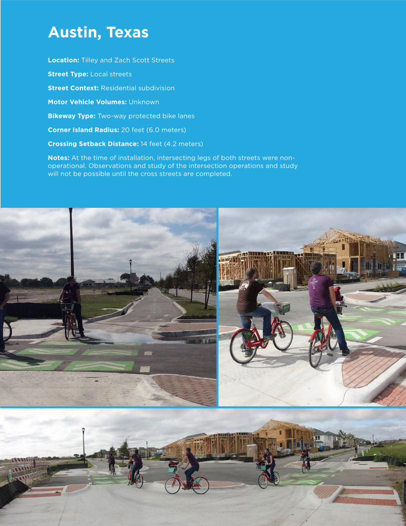
Austin, TexasLocation: Tilley and Zach Scott Streets
Street Type: Local streets
Street Context: Residential subdivision
Motor Vehicle Volumes: Unknown
Bikeway Type: Two-way protected bike lanes
Corner Island Radius: 20 feet (6.0 meters)
Crossing Setback Distance: 14 feet (4.2 meters)
Notes: At the time of installation, intersecting legs of both streets were non-operational. Observations and study of the intersection operations and study will not be possible until the cross streets are completed.

41
Photo Credit: Greg Griffin via Flickr (CC BY-NC 2.0)
Tilley St & Zach Scott St
Protected Intersection
Austin, TX
SCA
LE: 1” = 10’
020’
40’80’
Tilley St
Zach Sco
tt St
Tilley St & Zach Scott St
Protected Intersection
Austin, TXSCALE: 1” = 10’
0 20’ 40’ 80’

42
Davis, CaliforniaLocation: Cannery Avenue and East Covell Boulevard
Street Type: Arterial street at neighborhood collector
Street Context: Residential subdivision
Motor Vehicle Volumes: East Covell Boulevard, 20,000 ADT; Cannery Avenue, 3,500 ADT
Bikeway Type: On street bike lanes and shared use path
Corner Island Radius: 36 feet (11 meters)
Setback Distance: 22-32 feet (6.7-9.7 meters)
Notes: The Davis intersection functions with shared-use paths allowing bicycle movements in both directions mixed with pedestrian traffic. While similar in design to protected intersections with separated bike lanes, this design simplifies the waiting areas by not separating bicyclists and pedestrians.

43
Cannery A
venue & East C
ovell Blvd
Protected Intersection
Davis, CA
SCA
LE: 1” = 10’
020’
40’80’
Tilley St & Zach Scott St
Protected Intersection
Austin, TXSCALE: 1” = 10’
0 20’ 40’ 80’
Cannery Ave
E C
ovell Blvd

44
Chicago, IllinoisLocation: Washington and Franklin Streets
Street Type: Dedicated bus corridor; One-way streets
Street Context: Central business district
Motor Vehicle Volumes: Unknown
Bikeway Type: One-way separated bike lane with one-way buffered bike lane
Corner Safety Island Radius: 15 feet (4.5 meters) (approximate)
Crossing Setback Distance: 8 feet (2.4 meters)
Notes: Photographs show construction in progress. Constructed as part of Loop Link bus rapid transit project.

45
W W
ashington St & N
Franklin St
Protected Intersection
Chicaco, IL
SCA
LE: 1” = 10’
020’
40’80’
Washington St
Franklin St
Tilley St & Zach Scott St
Protected Intersection
Austin, TXSCALE: 1” = 10’
0 20’ 40’ 80’
46
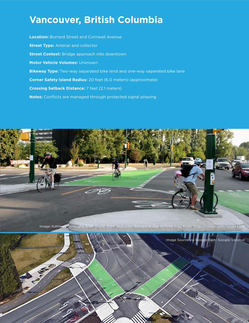
Vancouver, British ColumbiaLocation: Burrard Street and Cornwall Avenue
Street Type: Arterial and collector
Street Context: Bridge approach into downtown
Motor Vehicle Volumes: Unknown
Bikeway Type: Two-way separated bike land and one-way separated bike lane
Corner Safety Island Radius: 20 feet (6.0 meters) (approximate)
Crossing Setback Distance: 7 feet (2.1 meters)
Notes: Conflicts are managed through protected signal phasing
Image Source via Google Earh: Google; Landsat
Image: Kathleen Corey and Brian Gould. 2014. Seacycles: Burrard Bridge to Point Grey Road. https://vimeo.com/106894206

47
Burrard StC
ornw
all Ave
Tilley St & Zach Scott St
Protected Intersection
Austin, TXSCALE: 1” = 10’
0 20’ 40’ 80’
Image: Kathleen Corey and Brian Gould. 2014. Seacycles: Burrard Bridge to Point Grey Road. https://vimeo.com/106894206

48
Montreal, QuebecLocation: Rue Cherrier and Rue Berri
Street Type: Local street and major arterial
Street Context: Residential neighborhood
Motor Vehicle Volumes: Unknown
Bikeway Type: Forced turn of a two-way separated bike lane
Corner Safety Island Radius: 20 feet (6.0 meters) (approximate)
Crossing Setback Distance: 6 feet (1.8 meters)
Notes: Constructed out of planters and posts to allow for snow clearance
Image Source via Google Earth: Google; Landsat
Image Source via Google Maps

49
Rue Cherrier
Rue B
erri
Tilley St & Zach Scott St
Protected Intersection
Austin, TXSCALE: 1” = 10’
0 20’ 40’ 80’
Image Source via Google Maps

50
American Association of State Highway and Transportation Officials (AASHTO), 2011. A Policy on Geometric Design of Highways and Streets.
American Association of State Highway and Transportation Officials (AASHTO), 2012. Guide for the Development of Bicycle Facilities.
Association for Pedestrian and Bicycle Professionals (APBP), n.d. “Thread Summary: Truck Apron at Corner Radius.” list serve. http://lists.apbp.org. n.d. Web. 25 Sept. 2015.
City of Davis, 1972. Davis Bicycle Circulation and Safety Study. University of California – Davis.
CROW, 2006. Record 25: Design Manual for Bicycle Traffic. CROW, The Netherlands.
Falbo, N., 2014. Protected Intersections for Bicyclists.
Federal Highway Administration (FHWA), 2009. Manual on Uniform Traffic Control Devices.
Federal Highway Administration (FHWA), 2013. Interim Approval for Optional Use of a Bicycle Signal Face (IA-16).
Federal Highway Administration (FHWA), 2015. Separated Bike Lane Planning and Design Guide.
Fietsberaad, 2011. Publicatie 19b: Grip op fietsongevallen met motorvoertuigen: Samen werken aan een veilige fietsomgeving.
Florida DOT, 1994. Florida Trail Intersection Design Guidelines.
Geruschat, D. R. and S. E. Hassan, Driver Behavior in Yielding to Sighted and Blind Pedestrians at Roundabouts, Journal of Visual Impairment & Blindness, Vol. 99, No. 5, 2005.
Institute of Transportation and Traffic Engineering (ITTE), 1972. Bikeway Planning Criteria and Guidelines. UCLA.
Institute of Transportation Engineers (ITE), 2011. Planning Urban Roadway Systems: An ITE Proposed Recommended Practice.
Institute of Transportation Engineers (ITE), 2013. Separated Bikeways.
John Pucher and Ralph Buehler, 2008. Making Cycling Irresistible: Lessons from The Netherlands, Denmark, and Germany.
Kay Fitzpatrick and William Schneider. Turn speeds and crashes within right-turn lanes, College Station, TXx: Texas Transportation Institute, Texas A&M University System, 2005.
Lalani, N. 2001. Alternative Treatments for At-Grade Pedestrian Crossings. Institute of Transportation Engineers, Washington, D.C.
Massachusetts DOT (MassDOT). Separated Bike Lane Planning & Design Guide. 2015.
Monsere, Christopher et al. 2014. Lessons from the Green Lanes: Evaluating Protected Bike Lanes in the US.
National Association of City Transportation Officials (NACTO), 2012. Urban Bikeway Design Guide.
09 References

51
National Association of City Transportation Officials (NACTO), 2013. Urban Street Design Guide. Island Press.
National Cooperative Highway Research Program (NCHRP), 2010. Report 672 - Roundabouts: An Informational Guide, Second Edition.
National Highway Traffic Safety Administration (NHTS), 1981. The Effect of Right Turn On Red on Pedestrian and Bicyclist Accidents.
Road Directorate, 2000. Collection of Cycle Concepts. K. Larson & Son A/S.
Stanek,D. Alexander, C., 2015. Simulation Analysis of Intersection Treatments for Cycle Tracks.
United States Access Board. 2013. Proposed Guidelines for Pedestrian Facilities in the Public Right-of-Way.
Wagoner, W.D., 1992. “Driver Behavior at Right-Turn-on-Red Locations,” ITE Journal.
Wagenbuur, M., 2011. Junction Design the Dutch Bicycle-Friendly Way.
200 West & 300 South
Protected Intersection
Salt Lake City, UTSCALE: 1” = 10’
0 20’ 40’ 80’
LEARN MORE AT
WWW.ALTAPLANNING.COM