lessons learned in full composite aero-structures ... congress general lectures/2012/ishikaw… ·...
TRANSCRIPT

Lessons Learned in Full Composite
Aero-Structures Development in Japan
ICAS “Lawrence Hargrave” Lecture
for Innovation in Aeronautics, Sept. 25/ 2012
Professor, Aerospace Engineering,
Graduate School, Nagoya University
(Formerly Executive Director,
Japan Aerospace Exploration Agency)
Dr. Takashi Ishikawa

Outline of the Lecture
• Foundation of Mechanics of 2-D Textile Composites: Leading the World(1980-1985) Started at NAL, Continued in USA Stay (University of Delaware with Prof. Chou)
– Motivation: Full Composite Tail Plane Model of NAL STOL Research Aircraft
8 Harness Satin was Employed. Serious Warping in On-Ply Consolidation– Key: ng in Weave, Mosaic Model, Crimp Model, Bridging Model
・ Buckling and Post Buckling Compressive Failure of T-Stiffener
– Motivation: Immature Failure of Full Composite Tail, Buckling Induced Failure
– Nonlinear Analysis of T-Stiffener: Good Agreement with Experimental Results in CF/Epoxy
• Challenge to Clarification of Mechanics of Compression after Impact (CAI)
– Observation of Delamination Propagation, Clarification of Final Failure Process
– Numerical Simulation with Partner, Professor Suemasu: Cohesive Zone Element
• Mechanics of Compression after Impact (CAI) in Stiffened Panels
– Good Correlation of Numerical Prediction with Experimental Results
• Clarification of Interlaminar Strengthening Mechanism by Stitching
– Conception of Single Stitch Pull-Out Test and Observation by Micro X-Ray CT
• Contribution to Strength of Japan’s Aero-Industries in Composite Technology
• A Typical Example: 35% Work Share in Boeing 787 Production, Mostly Composites Portion, Particularly Main Wing

1st Topic: Mechanics of 2-D Textile
Composites, Triggered by Full CFRP
Horizontal Tail for NAL STOL R&D Aircraft
Initial Development: Sinusoidal Web Spar
⇒⇒⇒⇒8 Harness Satin Employed for Better
Drapability. Bending Failure in Web
Final Development: Model of Full CFRP
Horizontal Tail ⇒⇒⇒⇒8 Harness Satin, Used
in Front and Rear Spar
Extensive warping was generated by 1 ply 8-H Satin. ⇒⇒⇒⇒
The reason was unknown at that time: Request of consulting by
manufacturer ⇒⇒⇒⇒ Cause was easily estimated by observation of
sectional view of 8H Satin: Gate to “Treasure Island”

Pattern of 2-D Fabrics: Relationships between
Interlaced Region and Geometrical Repeat Number = ng
(a) ng=2: Plain Weave: Basic/No Anti-Symmetricity (b) ng=3: 2/1Twill Weave
(c) ng=4: 4 Harness Satin (Claw Foot Satin) (d) ng=8: 8 Harness Satin
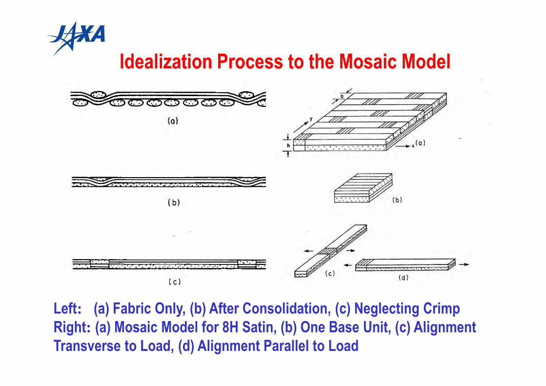
Idealization Process to the Mosaic Model
Left: (a) Fabric Only, (b) After Consolidation, (c) Neglecting Crimp
Right: (a) Mosaic Model for 8H Satin, (b) One Base Unit, (c) Alignment
Transverse to Load, (d) Alignment Parallel to Load
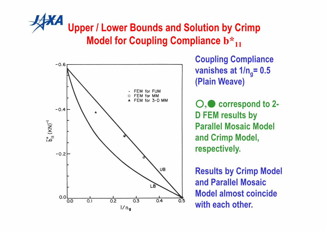
Upper / Lower Bounds and Solution by Crimp
Model for Coupling Compliance b*11
Coupling Compliance
vanishes at 1/ng= 0.5
(Plain Weave)
○○○○,●●●● correspond to 2-
D FEM results by
Parallel Mosaic Model
and Crimp Model,
respectively.
Results by Crimp Model
and Parallel Mosaic
Model almost coincide
with each other.
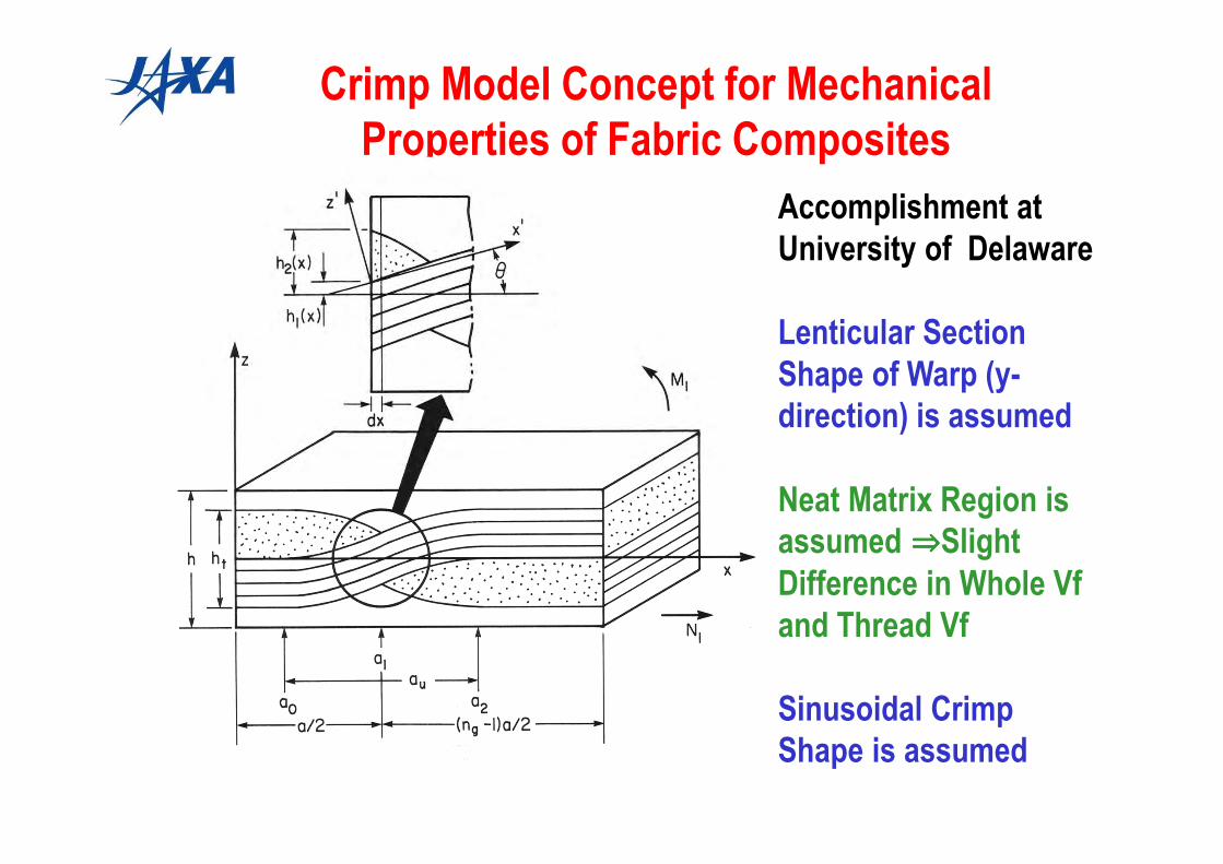
Crimp Model Concept for Mechanical
Properties of Fabric Composites
Accomplishment at
University of Delaware
Lenticular Section
Shape of Warp (y-
direction) is assumed
Neat Matrix Region is
assumed ⇒⇒⇒⇒Slight
Difference in Whole Vf
and Thread Vf
Sinusoidal Crimp
Shape is assumed

Upper and Lower Bounds of In-plane Stiffness A11
and A11 Results by Crimp Model
Upper and Lower Bounds
are Most Separated at
1/ng= 0.5
○○○○,●●●● Corresponds to
2-D (longitudinal and
thickness directions) FEM
Results of A11 for Serial
Mosaic Model and Crimp
Model, Respectively
One Dimensional Crimp
Model Provides Quite Low
A11 Value

Bridging Model for 8 Harness Satin
Basic Idea of the Model
Plain Weave Element Showing
Low In-plane Stiffness is
Surrounded by Fiber Cross-Ply
Element with Straight Fiber
Hexagonal Shape of Actual Unit
Cell of 8H Satin is Replaced by
Square with the Same Area
(This Model is only Feasible at
ng≥4)
Regions B, C, and D are
Assumed to Share the Same
Reference Strain and Curvature

Comparison of A11 by Bridging Model
and Crimp Model
Bridging Model Results Fall between Upper and Lower Bounds
Bridging Model Results Agree with 3-D FEM Results for 8H Satin

Comparison between Experiments and Theoretical
Predictions of Elastic Moduli of Textile Composites
Experimental Results were
Obtained in NAL
Dependency of Elastic Modulus
on Ply Numbers in Plain Weave:
Effect of Restraint of Out-of-
Plane Deformation by Stacking
of Multiple Layers
Experimental Results of 8H
Satin: Obtained by Back-to
Back 2 Ply Laminates
Predictions Coincides Basically
with Experiments

By-Product of Non-Linear Behavior Research of Textile
Composites in Tension: Longitudinal Hardening Non-
Linear Behavior of UD CFRP
Tensile Non-linear Behavior of Plain Weave Composites in Strip (one thread) Specimen
Cannot be Explained by Geometrical Non-Linearity Only ⇒⇒⇒⇒
Hardening Nonlinearity of CFRP in Fiber Direction must Be Introduced

[0]8ply Stress-Strain Curve
0
500
1000
1500
2000
2500
3000
0 2000 4000 6000 8000 10000 12000 14000 16000 18000
Strain (µε)
Str
ess
(M
Pa
)
IM600/Q -C133
Constitutive Equation Based on Higher Order Elasticity: Expression of Elastic
Modulus by Fractional Function of Stress of the Second Order
EL = 1/ (S11 + 2S111 σ1 + 3S1111 σ12) [Ishikawa, et al.: J. Mat.Sci. Vol.20]
UD-CFRP using Toray T-300: EL = 1000/ {6.689 + 0.982(σ1 – 1.10)2} [GPa]
By-Product of Non-Linear Behavior Research of
Textile Composites in Tension: Longitudinal
Hardening Non-Linear Behavior of UD CFRP

----1.01.01.01.0 0000 1.01.01.01.0
160160160160
140140140140
120120120120
100100100100
Equation 18
Equation A5
From[18]From[18]From[18]From[18]
Present workPresent workPresent workPresent work
Stress (GPa)Stress (GPa)Stress (GPa)Stress (GPa)CompressiveCompressiveCompressiveCompressive TensileTensileTensileTensile
(Lo
ngitu
dina
l Ten
sile
Mod
ulus
Long
itudi
nal T
ensi
le M
odul
usLo
ngitu
dina
l Ten
sile
Mod
ulus
Long
itudi
nal T
ensi
le M
odul
us)) ))
(GPa
)(G
Pa)
(GPa
)(G
Pa)
Non-linear Elastic Behavior of UD-CFRP
(Using Toray T-300) : Equation Explained
EL = 1/ (S11 + 2S111 σ1 + 3S1111 σ12)
Recent Paper with Yokozeki: Compressive
Behavior by Modified Sandwich Beam
Longitudinal Non-Linear Behavior
#29
Serious Elastic Modulus Reduction
at High Compression Strain
Longitudinal Hardening Non-Linear Behavior of
UD CFRP

Clarification of Compressive Failure Behavior
of Stiffeners of Aircraft Wing: Motivated by
Immature Failure of Full CFRP Horizontal Tail
After Bending Test at Ultimate Load by
Symmetric Down Forces at Wing Tips:Failure Location was Lower Flange in Aft Spar
Close-up Photo of Aft Lower Flange Spar
⇒⇒⇒⇒ Typical Buckling Induced Failure
Immature Failure at 74% of Predicted
Load ⇒⇒⇒⇒ Insufficient Understanding of
Spar Flange Buckling in Corrugated
Web Spar in Sine-Wave ShapeStress Strain Data near Failure Point

One More Incentive of Buckling Induced Failure,
Failure in Spar of “HOPE” Reentry Vehicle
Spar Material : CF/Polyimide, Failure was Induced by Buckling
Due to Inaccuracy of Temperature Prediction, too much Safety Factor ⇒⇒⇒⇒
Heavy Structure, Requirement of Precise Prediction of Buckling

Employed Specimen Geometry: T-Stiffener
Photo of Typical Buckling Deformation
Specimen : T-Stiffener = Element of Spar Flange or Stiffened Panel
Used Material : CF/Epoxy and CF/PEEK (Thermoplastic Composites)

Sectional Shape of Specimen and
Important Dimensions
So Called Unidirectional “Corner Filler: UD Noodle”””” is Inserted
If Specimen is Thin, Difference between bw and b’w = bw – t/2 is negligible
If Specimen is thick, This Difference should be Noticed
Modeling of Intersection Area is One Key Issue

Approximate Solution by Rayleigh-Ritz Method
Points: Sinusoidal in x (Longitudinal), Sine Hyperbolic in y (Transverse)
Purpose: Explicit Survey of Effect of D16,D26 (Bending- Torsion Coupling
Terms)
22
66
2
0 2
2
222
2
2
2
12
2
2
2
11 422
1
∂∂
∂+
∂
∂+
∂
∂
∂
∂+
∂
∂= ∫ ∫ yx
wD
y
wD
y
w
x
wD
x
wDΠ
a
o
b
p
dydxx
wN
yx
w
y
wD
yx
w
x
wD x
∂
∂+
∂∂
∂
∂
∂+
∂∂
∂
∂
∂+
22
2
2
26
2
2
2
16 44
Potential Energy under Out-of-Plane Deformation w, Πp, can be written as follows
Out-of-Plane Deformation Function, w(x,y) of One Piece of T-Stiffener,
Rectangular Strip of Three Simply Supported Edges and One Free Edge is
Assumed in the Following
+
⋅
=∑∑∑
= = = b
ypB
b
nyA
a
xmyxw mpmn
m n p
ππsinsinhsin),(
3
1
3
1
3
1
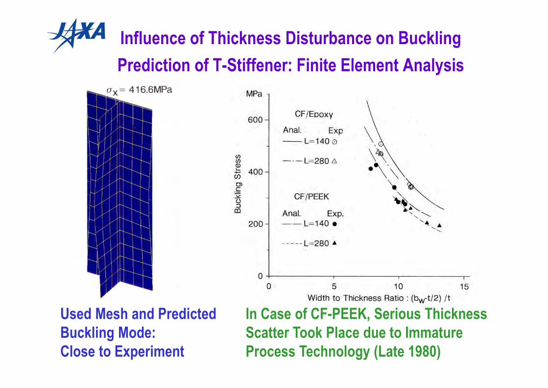
Influence of Thickness Disturbance on Buckling
Prediction of T-Stiffener: Finite Element Analysis
Used Mesh and Predicted
Buckling Mode:
Close to Experiment
In Case of CF-PEEK, Serious Thickness
Scatter Took Place due to Immature
Process Technology (Late 1980)

Predicted Buckling Deformation in Web( for W Type)
Considered Important Matters: Geometrical Nonlinearity (Analysis for
Deformed State), Appropriate Initial Imperfection, Precise Boundary
Conditions along Loading Edges, Mode of Loading
Above Results: Iso-value Contour of Out-of-Plane Deformation in Web
240.8MPa 356.0MPa 386.8MPa 416.6MPa 446.3MPa 475.6MPa

Comparison of Predicted Nonlinear Strain with
Experimental Results (for W Type)
Predicted Strain at Exact
Gage Location : 5mm Inside
from Free Edge at Central
Point in Terms of Loading
Direction
Loading Edge Boundary
Condition: Fixed is
Appropriate
Very Good Agreement with
Experimental Results

Predicted Failure Strength of T-Stiffener and
Experimental Results for CF/EpoxyPredictable if Consecutive
Failure does not Happen
Ratio of Width to
Thickness :
[(bf-t)/2]/t = 6.5 is Optimal,
Threshold between
Buckling Failure and
Material Failure
If This ratio is Larger than
6.5, Early Buckling
induces Lower Strength
Critical Ratio Depends on
Material

Buckling Critical Load of Sinusoidal Web Spar
Buckling is Sensitive to Distance to Free Edge
Numerical Results of Buckling Mode
Buckling Takes Place at Bottom of Sine
Length of Spar is
Different from Tested
Model
Prediction in 1982 was Done
Based on Flat Web due to
Computational Resources

Clarification of Mechanism of
Compression after Impact (CAI): Concept of CAI Test
Impact at Required Energy Level ⇒⇒⇒⇒ Determination of Delamination Area by
Ultrasonic NDE ⇒⇒⇒⇒ Compressive Strength Measurement
(a) Impact by Drop Weight (b) Non-Destructive Evaluation (c) Compression
Impactor
SpecimenDelamination
Compressive
Force

Strong Incentive of CAI Research:
7J7 Horizontal Tail Test Program
From 1988 to 1991, as Boeing-JADC-NAL(at that time) Cooperative Research
Test Venue: NAL Chofu , under Witness of Boeing
7J7: Code Name
of Imaginary
Aircraft
Actually
Prototype of
Boeing 777 Full
Composite Tail
Standard
Development
Sequence was
Taken

Outline of Full Composite Tail of 7J7,
Designed by Boeing,
Fabricated by Fuji Heavy Industries
Rough Drawing of the
Model and Basic
Dimensions
Photo of Robotic Ultrasonic C-Scan of Six
Impact Locations before Fatigue Loading
(Maximum Energy: 900lbs*in)
and Trigger Point of the Final failure and
Skin Split Line
Trigger Point of
the Final Failure
Split Line

Acoustic Emission Data of the
Final Failure Test of 7J7Full Composite Tail
The Final Failure was Triggered by Impact Point 3B (850lbs*in) [Most Active AE Signal
Generation]. Compression Failure with Delamination Propagated Instantaneously to
the Transverse Direction to the Main Load.
Wing Skin was Split like by Axe Strike (No Picture by Boeing Control)
Large Scale CAI Failure Happened. Importance of CAI was Strongly Believed

Essence of CAI Research Results:
Typical Delamination Damage Geometry
Impact Damage of Less Tough CF/ Epoxy
at High Energy Level (by NASA Method of CAI)
Example of Hat and Brim Shape Delamination

0
1000
2000
3000
4000
5000
0 1 2 3 4 5 6 7
SACMA STD
SACMA PF
NASA
Normalized Impact Energy (J/mm)
Del
amin
atio
n A
rea
(Pro
ject
ion
, mm
*2)
Essence of CAI Research
Relationship between Impact Energy per Thickness
and Delamination Area (Projection)
Energy Threshold for Delamination Creation is Identified
Leveling-off in Delamination Area at High Energy:
Delamination Edge is Approaching to Supporting Fixture

Relationships between Compression Stress
and Out-of-Plane Deformation at Delamination Center
in CAI Test ( CF/Epoxy & CF/PEEK)
All Delamination
Pieces Deformed
to the Same
Direction: Mode II
Component is
Dominant
Deflection Reverse
at Delamination
Pieces at Impact
Side : Mode I
Component is
Dominant
Delamination Buckling Behavior
and Measured Deformation
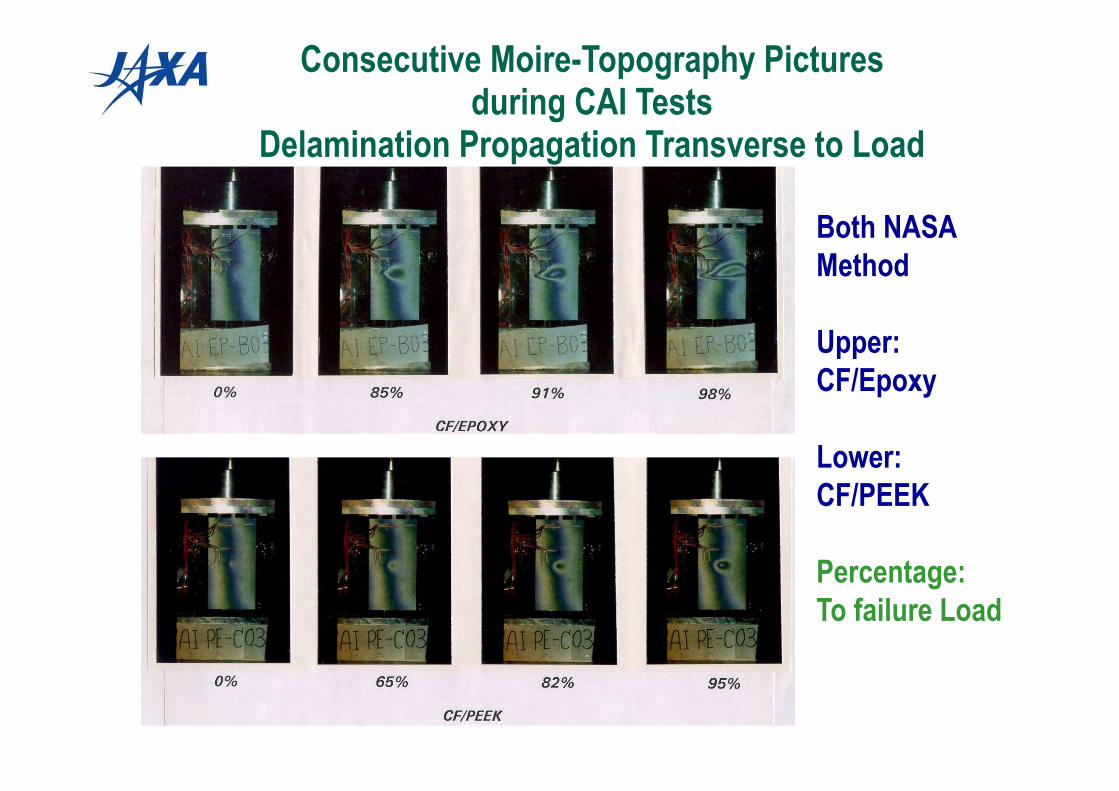
Consecutive Moire-Topography Pictures during CAI Tests
Delamination Propagation Transverse to Load
Both NASA
Method
Upper:
CF/Epoxy
Lower:
CF/PEEK
Percentage:
To failure Load

0
100
200
300
400
500
0 2 4 6 8
SACMA STD
SACMA PF
NASA
Normalized Impact Energy (J/mm)
CA
I Str
eng
th (
MP
a)
CAI Properties: Relationships
between Impact Energy per Thickness and
Compression Strength Reduction
Different Tendency in NASA and SACMA methods
Incentive to Find the Other Interpretation Parameter

Another Interpretation Parameter: Summation of
Delamination Area by Using B-Scope of Ultrasonic C-Scan
Geometrical Relationships about Imaginary Cylinder
Diameter of Accumulated Delamination
Rc = Ac/As = tDc /(t b) = Dc / b, Re = Ae/As = tDe /(t b) = De / b

0
100
200
300
400
500
0 0.1 0.2 0.3 0.4 0.5
SACMA
NASA
Sectional Area Ratio of Virtual Delam. Cylinder: Rc=Dc/b
CA
I Str
eng
th (
MP
a)
Relationships between Ratio of Imaginary Cylinder
Area of Delamination to Specimen Width and CAI Strength
Dc/b as Interpretation Parameter: Experimental CAI Strengths of
NASA and SACMA Methods Fall around the Same Curve

H. Suemasu, W. Sasaki, T. Ishikawa, Y. Aoki, A numerical study on compressive
behavior of composite plates with multiple circular delaminations considering
delamination propagation, Composite Science and Technology, 68, 2008, 2562-2567
Relationships between the applied load and the deflections of a delaminated portion (B) and
undelaminated portions (A and C) for a plate with four delaminations(4D40).
Assumed Circular Multiple
(Four) Delamination
Important Nature of the
Solution: Captured Load Drop
with Delamination
Propagation
By Suemeasu, Ishikawa et al.
Numerical Results Based on
Multiple Delamination with
Professor Hiroshi Suemasu,
Sophia University, Japan
Delamination Propagation Analysis Using
Cohesive Zone Element

Interface 1
Interface 3
Interface 2
Interface 4
59.71 kN 57.55 kN 52.93 kN60.50 kN 61.57 kN 60.61 kN 60.56 kN
40 mm
Loading Direction
Numerical Results Based on Multiple Delamination with
Professor Hiroshi Suemasu, Sophia University, Japan
H. Suemasu, W. Sasaki, T. Ishikawa, Y. Aoki, A numerical study on compressive
behavior of composite plates with multiple circular delaminations considering
delamination propagation, Composite Science and Technology, 68, 2008, 2562-2567
By Suemeasu, Ishikawa et al.
Important Nature
of the Solution:
Transverse
Propagation of
Delamination to
Loading Direction
Experimental Fact
without Exception

Challenge to Clarification of CAI Properties
in Stiffened Panel: Initial Target = Buckling Analysis
Results of CF/Epoxy Stiffened Panel for Reference = Non-Damaged Part of STOL Tail Wing
Final Purpose = Verification of High Damage Tolerance of CF/PEEK Structures

Comparison of Numerical and Experimental
1st Buckling Mode
Good Correlation was Obtained for Both
Buckling Load and Mode by Including
Aluminum End Platen Potted into Analysis
Photo for CF/PEEK with 4 T-Stiffeners

Relationship between Impact Energy per Thickness
and Delamination Area in Stiffened Panels
In CF/Epoxy Panels (Low Fracture Toughness), Delamination Area Tends to Narrower
over Threshold: Penetration Mode of Projectile is Dominant
CF/PEEK (High Fracture Toughness): Still in Proportional Region (under Threshold),
Rather Wider Delamination Area Complicated Findings
200
220
240
260
280
300
0 50 100 150 200 250
FEA (Clamped)FEA (Simply Supported)Experiment
Temperature (Deg. C)
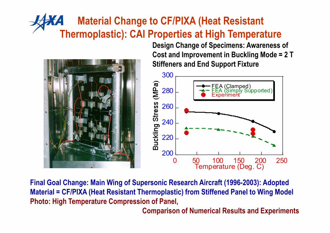
Final Goal Change: Main Wing of Supersonic Research Aircraft (1996-2003): Adopted
Material = CF/PIXA (Heat Resistant Thermoplastic) from Stiffened Panel to Wing Model
Photo: High Temperature Compression of Panel,
Comparison of Numerical Results and Experiments
Material Change to CF/PIXA (Heat Resistant
Thermoplastic): CAI Properties at High TemperatureDesign Change of Specimens: Awareness of
Cost and Improvement in Buckling Mode = 2 T
Stiffeners and End Support Fixture

0 2 4 6 8 10
0
100
200
300
400
500
Normalized Impact Energy (J/mm)
CAI S
treng
th (MPa)
CF/Epoxy,4T
CF/PEEK,4T,FY89
CF/PIXA,2T
Concluding Experimental Results:
CAI Properties of Stiffened Panels (at Room Temperature)
Compression over
200゚゚゚゚ C Epoxy Potting:
Not Available
End Fixture was
Designed
Dimensions of Panel:
Inter-Bay Width and
Length, Improved to
Realize 4 Half Waves
at the 1st Mode
Conclusion of CAI Properties of
Composite Stiffened Panels
Overwhelmingly Excellent Results of
CF/PIXA, Almost Insensitive to Impact
Vanished due to Cost, Unfortunate

Research of Mechanics of
Interlaminar Strengthening by Stitching
Concept of Stitching and basic
Geometrical Parameter
Photo of Consolidated Flat Panel
after Stitching
(Carbon Fiber Stitching)
(1983-2007)
Stitched by Mainly Kevlar® Threads,
Some are by Carbon Threads with
Special Technology

4.0(Ref.)
0.30
A-AStitch Thread
Interlocking point
A A
□12.5□5.0(Ref.)
needle
bobbin
Conception of Single Stitch Thread Pull-Out
Specimen and Observation of Behavior by
Micro X-ray CT
With Stitch
Thread
0
100
200
300
400
500
600
700
0.00 0.50 1.00 1.50
開口変位(mm)
荷重
(N
)
Interlaminar Failure of CFRP
Failure of Stitch Thread
Pull-Out of Thread from CFRP
Load Carried by CFRP
Stitch Thread
Tensile Deflection (mm)
Load
(N)

0.0
2.0
4.0
6.0
8.0
10.0
12.0
14.0
16.0
0.0 1.0 2.0 3.0 4.0
Vst (%)
GIR
(N
/m
m)
Experimental Withput pull out thread effect With pull out thread effect
GIR-Vst plot with DCB test data
Relationship between Mode I Energy Release Rate and
Volume Fraction of Stitch Thread:
Comparison of FEM Simulation with Experiments

History of Composites Application to Aircraft
Cost Limits in
Commercial
Applications
If stick to
Traditional
Airbus A380
Boeing
B 787

Material Usage in Boeing B-787
Carbon laminate
Carbon sandwich
Fiberglass
Aluminum
Aluminum/steel/titanium pylons
Building on Proven MaterialsBuilding on Proven Materials
Composites
50%
Titanium
15%
Other
5%Steel
10%
Aluminum
20%
Courtesy of Boeing

←Mitsubishi Heavy I ↑Fuji Heavy I
Photo of B787 Main Wing Production
Contribution of the Award Recipient
Affects Somewhat This Japan’s
Production Share
Japan’s Aero-Industries Obtained 35 %
Production Share in Boeing B-787: Mostly Composites

Impressive Photo of Ultimate Test of
B-787 Full Composite Main Wing
Courtesy of Boeing Website

Lessons Learned in Full Composite
Aero-structure Development• Foundation of Mechanics of 2-D Textile Composites: High Impact Factor Papers
– One Drawback: Interruption after Clarification of Fundamental Mechanics• A Honor of Completion of the Theory Went to Dr. Naik, India
• Buckling and Post Buckling Induced Failure of Stiffener– Nonlinear Analysis of Postbuckling Behavior: Simple Maximum Stress Theory
Provides Prediction of Compressive Strengths = Good Agreement with Test– Finding the Optimal Width/Thickness Ratio in Stiffener
• Clarification of Compression after Impact (CAI) Mechanics– Introduction of High Performance Ultrasonic C-Scanner and Moire-Topography
Camera played a Key Role = Observation Equipments are Important
– Theoretical Predictions: Assistance by Professor Suemasu, Leading World• Mechanics of Compression after Impact (CAI) of Stiffened Panels
– Double Incentive: Demonstration of Damage Tolerance of Thermoplastic Composites, CF/PIXA Shows Extremely Excellent Insensitivity to Damage
• Cost (Material and Tooling) is Serious Issue = Forced to Quit
• Mechanism of Interlaminar Strengthening by Stitching– Pull-Out Tests of Single Stitch Thread: Understanding of Energy Dissipation
• In Conclusion, Accumulation of Lessons Learned by Award Recipient Raise Potential of Japan’s Aero-Structure Industries in Composites Area
• A Typical Proof: 35% Work Share in Boeing 787 Production by Composites

51
Thank you! for your kind attention