lessons learnt from the design and construction of third karnaphuli bridge
TRANSCRIPT

77
1 INTRODUCTION The Third Karnaphuli Bridge is a Prestressed Concrete Extradosed Box Girder Bridge. The bridge is 950m long and 24.47m wide. The bridge is on Chittagong-Cox Bazar Highway (N-1) over the river Karnaphuli at the east side of Chittagong Port City of Bangladesh. The bridge has the curved span of 200m and it is the longest curved span in the world in the case of Prestressed Concrete Extradose Box Girder Bridge until now. A long section of Third Karnaphuli Bridge is shown in Fig- 1.
Fig-1: Long Section of Third Karnaphuli Bridge
Chittagong has been developed with its port and become the number one commercial city of Bangladesh. The Chittagong city is developed on the bank of Karnaphuli River. As the river Karnaphuli has separated the city, the growth of the city has been hampered due to inadequate road connection over the river. Though there are two bridges exist over the river Karnaphuli and they are not enough for the existing traffic demand.
The Old Shah Amanat Bridge is situated about 10 Km from the Chittagong Port and the Railway bridge at Kalurghat is further 2 Km upstream of Old Shah Amanat Bridge. The Old Shah Amanat bridge is a road bridge with steel truss and timber decking. The structure is no longer appropriate for modern traffic usage and heavy vehicles are prohibited over it. The Kalurghat Bridge is over 80 years old and is originally a single track Rail bridge later on converted to rail cum road bridge. The bridge decking and approaches are very nar-
IABSE-JSCE Joint Conference on Advances in Bridge Engineering-II, August 8-10, 2010, Dhaka, Bangladesh. ISBN: 978-984-33-1893-0 Amin, Okui, Bhuiyan (eds.) www.iabse-bd.org
Lessons learnt from the design and construction of Third Karnaphuli Bridge: The first extradose cable stayed bridge of Bangladesh
Abu Saleh Md Nuruzzaman Roads and Highways Department, Bangladesh and Project Manager, Third Karnaphuli Bridge Project ABSTRACT: Bangladesh entered into the era of extradose bridge through the design and construction of the Third Karnaphuli Bridge. The paper gives an overview of the project from the perspective of a project man-ager and records the salient aspects of this milestone development for the engineers of the future. It is be-lieved that the lessons learnt from the project as documented in the paper will be helpful also for the future decision makers in maintaining the bridge and designing future life-links of this type.
DHFL +4.30SLWL +0.40LLWL -1.57
SHWL +3.500.00 DATUM
-65.00-65.00-65.00-65.00
-50.00 -50.00
76000NAVIGATION CHANNEL
4No. 3m DIAMETER BOREDCAST IN-SITU PILES.
4No. 1.5m DIAMETER BOREDCAST IN-SITU PILES.
4No. 1.5m DIAMETER BOREDCAST IN-SITU PILES PER PIER
76000NAVIGATION CHANNEL
12No. 1.5m DIAMETER BOREDCAST IN-SITU PILES.
EXPANSIONEXPANSIONEXPANSION
4No. 1.5m DIAMETER BOREDCAST IN-SITU PILES
JOINTJOINTJOINT
-50.00
ACCESS PLATFORMS ATPIERS 6, 7, 8, 9 AND 10
Approach Viaduct 16+4x22+16 m Main Bridge 115+3x200+115 m
Main bridge and approach viaduct- Bridge Width 24.47m
- 2 way 6 lanes and each side 1.5m pedestrian walkway
-78 -69 -63-74

78
row and road traffic used to suspended during train movements. For all these reasons Govt. of Bangladesh had decided to build a wide and permanent road bridge. This new bridge will solve all these problems. The location of the bridge is shown in Fig-2. The Third Karnaphuli Bridge has been constructed 50 meter up-stream of Shah Amanat Bridge as a replacement of it. This bridge will establish link to the Asian Highway, facilitate the trans border trade with South East Asia through Myanmer, encourage growing tourist industry at Cox’s Bazar, encourage the economic and social development of the regions of Bangladesh, enhance expand-ing Chittagong City on South Bank of Karnaphuli, create new industrial belt around the port and improve road transport efficiency in terms of cost and travel time.
Fig-2: Location of Third Karnaphuli Bridge
At the beginning it was planned to construct PC box girder bridge for Third Karnaphuli Bridge. But since the Chittagong Port Authority and different quarters expressed their concern that if the number of piers in the river are more than these may cause rapid deposition of silt in the downstream of the river near the port area and affecting the navigation. And there was demand for a long span bridge. Considering all these a cost effec-tive span of 200m with extradosed bridge system was proposed for Third Karnaphuli Bridge.Under this cir-cumstance RHD had decided to investigate hydro morphological changes especially in the Chittagong port area due to construction of the Third Karnaphuli Bridge. From hydro- morphological study it was understand that the existing Shah Amanat bridge along with proposed Third Karnaphuli Bridge might not affect signifi-cantly in sedimentation at Chittagong port area.
2 GENERAL DATA AND STRUCTURAL TYPE
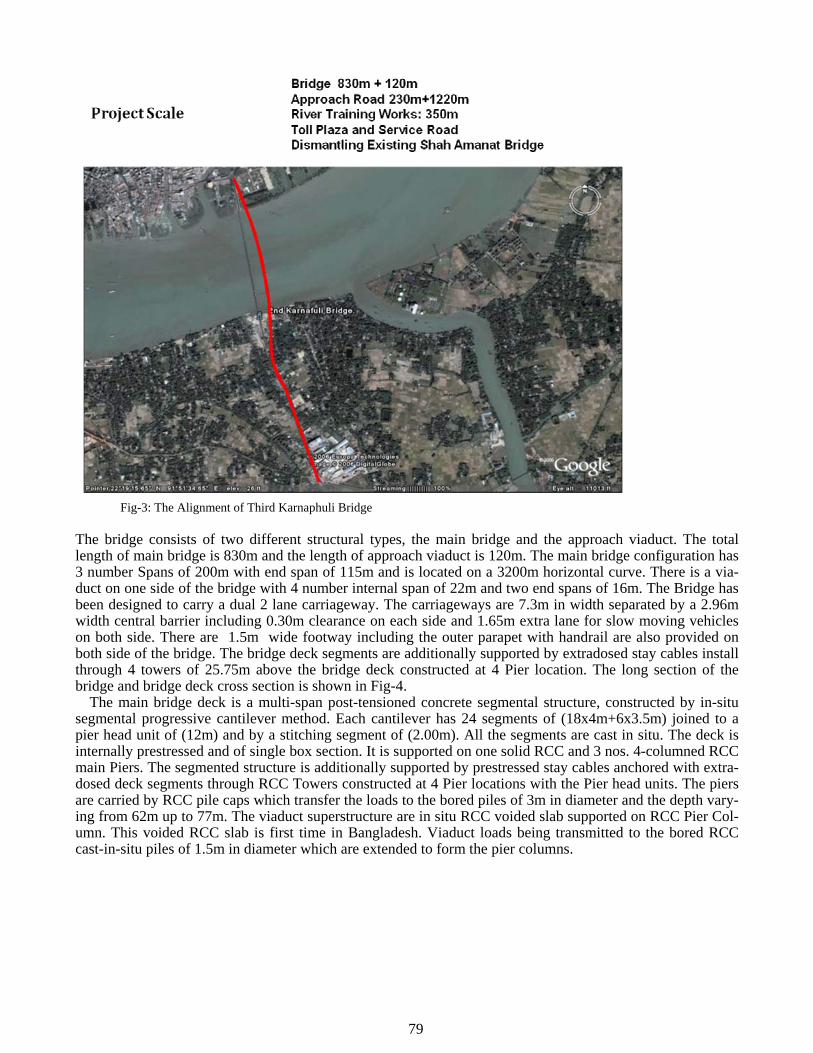
The bridge is located 50m up stream of existing Hazrat Shah Amanat Bridge and 2km up stream of Chit-tagong Port. As both sides of the bridge are congested with the commercial occupancy and the river is mean-dering around the bridge the geometric alignment becomes an asymmetrical curved both in vertical (V=3% to 4.0%, R= 6780m) and in horizontal (R=3200m) directions. And this was done in order to keep navigational clearances and to reduce land acquisition cost. In the case of long span Prestressed Concrete Extradosed Bridge, the curved alignment is quite rare in the world. The alignment of the bridge is shown Fig-3.
79
Fig-3: The Alignment of Third Karnaphuli Bridge
The bridge consists of two different structural types, the main bridge and the approach viaduct. The total length of main bridge is 830m and the length of approach viaduct is 120m. The main bridge configuration has 3 number Spans of 200m with end span of 115m and is located on a 3200m horizontal curve. There is a via-duct on one side of the bridge with 4 number internal span of 22m and two end spans of 16m. The Bridge has been designed to carry a dual 2 lane carriageway. The carriageways are 7.3m in width separated by a 2.96m width central barrier including 0.30m clearance on each side and 1.65m extra lane for slow moving vehicles on both side. There are 1.5m wide footway including the outer parapet with handrail are also provided on both side of the bridge. The bridge deck segments are additionally supported by extradosed stay cables install through 4 towers of 25.75m above the bridge deck constructed at 4 Pier location. The long section of the bridge and bridge deck cross section is shown in Fig-4.
The main bridge deck is a multi-span post-tensioned concrete segmental structure, constructed by in-situ segmental progressive cantilever method. Each cantilever has 24 segments of (18x4m+6x3.5m) joined to a pier head unit of (12m) and by a stitching segment of (2.00m). All the segments are cast in situ. The deck is internally prestressed and of single box section. It is supported on one solid RCC and 3 nos. 4-columned RCC main Piers. The segmented structure is additionally supported by prestressed stay cables anchored with extra-dosed deck segments through RCC Towers constructed at 4 Pier locations with the Pier head units. The piers are carried by RCC pile caps which transfer the loads to the bored piles of 3m in diameter and the depth vary-ing from 62m up to 77m. The viaduct superstructure are in situ RCC voided slab supported on RCC Pier Col-umn. This voided RCC slab is first time in Bangladesh. Viaduct loads being transmitted to the bored RCC cast-in-situ piles of 1.5m in diameter which are extended to form the pier columns.

80
Fig-4: Long Section and Cross Section of Third Karnaphuli Bridge 3 THE EXTRADOSED BRIDGE SYSTEM An extradosed bridge employs a structure that is frequently described as a blending between a box girder bridge and a cable-stayed bridge. The name comes from the French word extradosse, which is derived from the word extrados. A typical cable stayed bridge has a tower with a height above the deck at least half the span to the next support, since the cables are the vertical support and must come at a relatively high angle. In an extradosed bridge, the deck is directly, supported by resting on part of the tower, so that in close proximity to the tower the deck can act as a continuous beam. The cables from a lower tower intersect with the deck only further out, and at a lower angle, so that their tension acts more to compress the bridge deck horizontally than to support it vertically. Thus stay cables act as prestressing cables for a concrete deck, made of a box girder.
The extradosed bridge resembles more closely that of a continuous girder bridge with external prestressing. The main characteristic of extradosed bridges is the arrangement of external cables, as opposed to placing it inside the girder. The stay cables behave like prestressing cables passing over the pylons that act as deviator thus adding eccentricity to the tendons. A comparison between Continuous Box Girder Bridge, Extradosed Bridge and Cable Stayed Bridges are shown in Table-1.
Table-1: Characteristics of 3 Types of Bridge
24.4702.360
0.3000.3007.3007.300 1.6501.650 1.5001.500
2.5% 2.5%
2 Lane 2 Lane SlowVehicle
Sidewalk
SideWalk
4.00
0 ~
6.7
502
1
0.305 0.305
SlowVehicle
Cross Section of Superstructure
Profile of Superstructure
830.0
115.0 3x200.0 =600.0 115.0
P6 P9 P8 P� P10 A2
Model of Main Girder
Inside of Box Girder
Cable Strut

81
Extradosed bridges are similar to cable-stayed bridges and the stay cables are used for strengthening. Ex-tradosed bridges, a concept introduced by J. Mathivat in 1988. have tow main characteristics. One is the al-lowable stress of stay cables which is the same as that of internal cables. The other is the saddle at the top of the tower. The extradosed bridges are distinguished from cable stayed bridge in their structural aspect. The extradosed solution was also used in France, its country of origin, to construct the Saint-Remy Bridge in 1996. Though the extradosed bridge system was introduced by French but it is widely used in Japan since 1994 and in China since 1999. There are about 30 extradosed bridges in Japan and 13 extradosed bridges in Japan have already been built.
The Third Karnaphuli Bridge is an Extradosed Type Bridge. Resembles more closely in appearance the standard cable stayed bridge, its structural behavior is more inclined to that of a continuous girder bridge. The bridge form for extradosed bridges would be a continuous deck girder supported by towers, which are made continuous with the decks and external cable anchored to deviators above the deck. The external cables are very similar in form and appearance with the stay cable of cable stayed bridges. Depth of box girder of Third Karnaphuli Bridge at support is 6.75m and at mid span is 4.0m. But in the case of Bhairab Bridge the span length is 110m and depth of box girder at support is 6.0m and at mid span is 2.70m. Almost with the same depth of box girder of Brairab Bridge the Third Karnaphuli Bridge has a double span length than that of Bhairab Bridge. In a simple sentence extradosed bridge system is a continuous prestressed box girder system post-tensioned internally and externally associated with shallow towers. This shallow tower pulls the box sec-tion by the help of stay cables associated with shallow tower. In this system stay cables and tower are act as external post-tensioning system.
According to Mathivat, the optimum girder height is 1/30 to 1/35 of the main span length and the tower height is 1/15. In particular, the tower height is half of the optimum value of cable-stayed bridges. Extradosed bridges are an intermediate type between box girder bridges and cable –stayed bridges. The quantities of all materials in extradosed bridges lie mid-way between girder bridges and cable-stayed bridges. Construction is also easier than for cables-stayed bridges, as the height of the main tower is only around half that of a cable-stayed bridge of similar size. Cable-Stayed, extradosed and externally prestressed bridges can be treated as the same category of the structure reinforced by stay cables.
Since the stay cable inclination for extradosed bridges in much less than that for conventional cable stayed bridges, the variation in stress due to live loading is lesser. Under these circumstances, the allowable stress for stay cables are taken as 60% of the cable tensile strength as opposed to 40% only for conventional cable stayed bridges. There are various types of stay cable available, from epoxy-coated strand and galvanised strand with polyethylene coating to prefabricated galvanised with polyethylene sheathing. An allowable stress of 0.6 fpu is used for the extradosed cables on each of the bridges in fatigue design, it is difficult to evaluate the vibration of the stay cables due to the wind. For this reason, dampers were provided for the extradosed cables. In the design of stays, the fatigue limit state is usually critical, unlike suspension bridges, the stress change on a cable-stayed bridge will differ depending on the stays, so it is not rational to define the allowable stress using a single value of 0.4fpu . The extradosed bridge system is advanced form of box girder system. Generally continuous box girder bridges are constructed by following progressive cantilever method. Now a days to avoid central hinge, stitching techniques are used. During construction of continuous box girder bridge by following progressive cantilever method, total load of the cantilever portion is carried by internal post-tensioning of box section. And incase of extradosed bridge system load of the cantilever portion is also taken by stay cables. By this way upto 30% DL of box section is taken by stay cables during cantilever construction. So the span length of same box section can be increased. After stitching of the cantilever portion the structure become continuous and its carrying capacity is also increased. In case of road bridge 80% of LL is taken by continuous box se tion, only 20% of LL is taken by stay cables. The stay cables of extradosed bridge experience very little repeated loading. After stitching segments are cast, the completed structure becomes indeterminate. The continuing creep strains and loss of prestressing due to stress relaxation, among others, becomes restrained by the boundary condition of the completed structure causing a shift in the shear and bending moment diagrams. The forces are redistributed with the reduction in dead load negative moments at mid span. Such behavior needs to be assessed carefully. 4 DESIGN STANDARDS
The design of Third Karnaphuli Bridge has been carried out in accordance with AASHTO LRFD BRIDGE DESIGN SPECIFICATIONS (SI Units Third Edition 2004 and 2006). AASHTO LRFD does not contain spe-cific guidance on the design of extradosd type bridges. However, according to established practice, the stay cables of the extradosed bridge span have been designed as external prestressisng, but with the stress in the cables limited to a value dependent on the fatigue behavior of the anchor and deviator system used. Other as-

82
pects of stay cable design such as wind/ vibration and catenary behavior, and cable removal/ replacement are covered by the AASHTO LRFD. 5 BRIDGE FOUNDATION
The substructures has to provide vertical support to the bridge deck and resist lateral forces from seismic events and ship impact. Because of the anticipated scour depths of up to 30m, 3m diameter piles have been used under each of the 4No main pier legs. This is the smallest pile diameter which can be used to provide sufficient lateral load resistance without slenderness under axial loads becoming the dominant effect. The four main piers are carried by RCC pile caps which transfer the loads to the bored piles of 3m in diameter and the depth varying from 62m up to 77m. Viaduct loads are being transmitted to the bored RCC cast-in-situ pile of 1.5m in diameter which are extend to form the pier column.
The piles are designed to transfer the vertical and horizontal loads from the deck into the ground so are de-signed for vertical forces due to self weight of the bridge and piers, finishes and live loads and horizontal forces due to braking, wind, ship impact (on piers), hydrodynamic flow and seismic. Of these effects the most critical for shear and flexural design is seismic in combination with dead load, in the scoured and unsecured condition.
The axial load capacity of 3m diameter and 1.5m diameter pile has been calculated by using frictional and end bearing resistance based on SPT N’ values and results from the pile load test. The pile load test was done on 1.5m diameter test pile by osterberg cell method. The benefits of base grouting have been proven by the results of the pile load tests. Later on base grouting of large diameter piles were incorporate. From pier 7 to pier 10, the base/ side grouting has been successful in stiffening the pile toe and improving frictional resis-tance.
For pile load test the self balanced load cell test method which is similar to osterberg cell (O-cell) test method. In this method after completion and cleaning of borehole the reinforcement cage with load cell at-tached 1m from bottom level was inserted in the pile hole and concreted the pile. The O-cell is a sacrificial jack like device installed within the pile. The O-ell is specifically engineered to offer negligible internal fric-tion even with eccentric movement. A typical level for the O-cell can be determined where there will be equal capacity above and below to maximize the pile capacity. After the concrete reaches a minimum strength, the test may be started. Separation of the pile into two elements is induced by hydraulic pressure applied at the cell. As the load is applied to the O-cell, it begins working in two directions; upward against upper skin fric-tion and downward against bas resistance and lower frictional capacity (if applicable), the O-cell test requires on reaction beam or anchor piles. The test is considered complete after reaching ultimate capacity above or below the O-cell or upon reaching the maximum capacity of the O-cell. The test pile includes monitoring of strain gauges embedded in the shaft. The arrangement of load cell in rebar cage and progress of O-cell pile load test is shown in Fig-5. Fig-5: Arrangement of Load Cell in Rebar Cage and Progress of O-cell Pile Load Test 6 MAIN BRIDGE SUPERSTRUCTURE DESIGN
The main bridge consists of a prestressed concrete box girder deck supported on 4No bearings at each of the main piers, so there is a carry-over of deck moments into the substructure under unequal span liver loading and 2No bearings at Pier 6 and the South Abutment. The deck is prestressed longitudinally by internal bonded prestressing tendons passing through the top and bottom slabs. Additional support is provided by 6No stay cables passing over reinforced concrete towers which are integral with the deck. The stay cables, which are

83
anchored at the centerline of the deck act like external prestressing enhancing the vertical shear capacity close to the piers. The reinforced concrete deck is braced against transverse distortion by diagonal struts which also provide a load path for the stay cable forces into the main vertical webs. Local traffic loads are carried by the reinforced concrete top slab, which is transversely prestressed over the stayed deck section.
Longitudinal Design: The global design of the maim bridge deck has to comply with the AASHTO LRFD requirements for the service and strength Limit States. At the Service Limit state, fibre stresses must remain within permissible limits and at the strength limit state the shear, torsion and flexural strength must be ade quate. Internal diaphragms have been provided in the box girder deck at piers, above each pair of bearings, and at the end of the haunch section where the bottom compression flange must be stabilized, and the com pressive stress is at a maximum. Every stage of construction (traveler movement, segment casting, stressing etc) has been modeled to provide an envelope of design forces at all stages which takes full account of the ef fects of creep and shrinkage. Bridge deck moment envelop and deck displacement due to creep in longitudinal direction of Third Karnaphuli Bridge is shown in Fig-6 and in Fig-7.
Fig-6: Bridge deck moment envelop in longitudinal direction of Third Karnaphuli Bridge
Fig-7: Deck displacement due to creep of Third Karnaphuli Bridge in longitudinal Direction

84
Transverse Design: There are three types of transverse sections which have been considered in the design. These are pier and abutment diaphragms at bearings, non-stayed deck sections and stayed deck sections. The design of diaphragms has been by use of “strut and tie” idealizations and conventional shear/ torsion codified design methods. The pier diaphragms are particularly complex since tower forces must be transferred into the bearings through large transfer beams which connect to the vertical diaphragm walls. Some preliminary finite element modeling has been carried out to understand the flow of forces.
Deck Cross-Section: In order to minimize weight a slender single cell prestressd concrete box girder deck has been use. The top slab is prestressd transversely over the stayed length of deck to balance the horizontal component of the stay forces. The overall deck depth is primarily dictatd by the requirements of free cantile-ver construction. The depth reduces from 6.5m at the pier to 4m at the location of the first stay cable, then remains constant to the midspan stitch. The web thickness has been kept constant to simplify the design of the form travelers. Compared with a fully cantilevered box girder deck, the extradosd deck depth is shallower to-wards the supports and has less web area, reflecting the effectiveness of the stay cables in reducing the verti-cal shear forces. 7 STAY CABLE A single plane consisting of 6No cables per pier is located on the bridge centerline. The cables are continuous from deck anchorage to deck anchorage passing through deviator bundle of tubes at the top of the towers. The reinforced concrete towers are cast integrally with the deck. The cable anchorages are located in alternate 4m long deck segments at the start of the constant depth section. A typical cable system for Third Karnaphuli Bridge is shown in Fig-8. Compared to a conventional cable stayed bridge deck, an extradosed bridge deck has greater flexural stiffness and carries significant shear and moment. For the Karnaphuli design, approxi-mately 15% of vertical dead load is picked up by the cables and transmitted to the towers.
Fig-8: A typical cable system for Third Karnaphuli Bridge
Stay cable was stressed, at the time of installation, to an initial design force which was equal to approxi-mately 50% of the breaking load. During subsequent deck construction the forces in stay cable was increased, depending on the deflection of the deck. Because of the relatively high stiffness of the deck compared to the stay cable system, the fluctuating stresses in the stay cables due to transient loads was very low, so that forces of up to 701% of breaking load were permissible based on fatigue stress limits. All stay cables will be reten-sionable (from within the deck) and replaceable, and the bridge has been designed (as an Extreme event) for

85
sudden loss of any stay cable. The deck anchorage of stay cables of Third Karnaphuli Bridge is shown in Fig-9.
Fig-9: The deck anchorage of stay cable of Third Karnaphuli Bridge
The design of the stay cable system includes a “multi-pipe” saddle which significantly reduces peak concrete stresses in the tower top compared to a single pipe system. A fixed “blocking: system will be used to prevent slippage at the saddle due to unequal forces in the stay cables under live loading. Dampers are provided at an-chorages to minimize fatigue effects due to wind vibration. Dampers anchorage system of stay cable finished tower with stay cable and saddle of Third Karnaphuli Bridge are shown in Fig-10.
Fig-10: Dampier anchorage system of stay cable finished tower with stay cable and saddle of Third Karnaphuli Bridge

86
8 APPROACH VIADUCT
The approach viaduct consists of a reinforced concrete voided slab deck with 4No internal spans of 22m and end spans of 16m, supported by reinforced concrete pier bents and end abutments. The false work of void was made by local “tulla wood” and the is was permanently embedded in the slab. The deck is built in to the pier columns and supported on free bearings at the abutments so that horizontal movement at the piers due to seismic effects, creep/ shrinkage and temperature are resisted by column flexure. The deck consists of a voided slab with transverse solid diaphragms at each pier and at the abutment. The diaphragms have been de-signed to sustain the seismic forcs from the columns elastically to ensure that plastic hinging occurs in the columns and not in the deck. The long and cross section of voided RCC slab is shown in Fig-11.
Fig-11: Long and cross section voided RCC slab of Third Karnaphuli Bridge 9 MATERIAL AND MATERIAL TESTING
The materials used in this bridge are concrete of difference grades, grade-60 reinforced bar and high strength stressing wires and cables. Except high strength stressing wires and cables other materials are procured and produced locally. In foundation and sub structure works grade-30 concrete (28 day cylinder compression strength 30N/mm2, 4351 psi) has been used. Grade-30 concrete produced by OPC and Bholaganj crushed stone. For super structure i.e. in main bridge and in tower grade C-50 (7250 psi) concrete has been used. Con-crete batching plant and material testing facility at Third Karnaphuli Bridge site is shown in Fig-12.
Fig-12: Concrete batching plant and material testing facility at Third Karnaphuli Bridge site

87
Grade C-50 concrete has been produced by using selected crushed Bholaganj boulder with OPC in associa-tion with some water reducing admixture and at low water cement ratio. The admixture JM-PCA is a con-crete super-plasticizer. It is poly-carboxylate polymer based composite admixture. It has a high range of water reduction capacity, high slump retaining ability and increase compression strength. In all proposed mix design the maximum admixture content was 1.2% of by weight of cement and the dose was according to manufac-turer recommendation. The water/ cement ratio was 0.29 (Avg) used for C-50 concrete. Composite cement CEM-II i.e sulphate resistance cement was used in foundation and substructure work.
Concrete strength and steel rebar were tested at site lab oratory in Third Karnaphuli Bridge site. High strength stressing wires were tested in China, at BUET and at Third Karnaphuli Bridge site. 10 SEISMIC BEHAVIOR AND ARTICULATION ARRANGEMENTS The bridge is located in BNBC Seismic Zone 2 which gives a peak spectral acceleration of 0.375g in the hori-zontal direction for soil type III. The lowest eigenvalue modes for the natural frequency analysis for a given periods of 2.5sec to 1.0sec resulting in mean modal accelerations of 0.10g to 0.25g is shown in Fig-13. The inertial forces are transmitted from substructure to superstructure at each of the main piers by a combination of shock transmission units and transverse buffers and at pier 6 and the South Abutment by transverse shear keys. At the fixed pier, there is one centrally placed shear key which is capable of carrying the peak seismic force. Ductility in the system is provided by plastic hinging in the columns of the main piers. Concrete stops on pier and abutment tops and deck diaphragms provide a “failsafe” system to prevent the deck losing support from the piers and abutment under severe seismic movement or in the event of mechanical failure of the shock transmission units.
Fig-13: The lowest eigenvalue modes for the natural frequency analysis for a given periods
The bridge deck is continuous between expansion joints at t6he South Abutment and pier 6 giving a total ex-pansion length of 830m. At each main pier there are 4No vertical bearings which transmit the deck loads through the substructure directly into each pile resulting in minimum substructure weight. The bearing ar-rangement provides a stable platform for deck cantilevering and attracts significant moments from out of bal-ance effects of live load and wind and reducing midspan moments. Horizontal fixity in both longitudinal and transverse directions is provided at per 8 and horizontal transverse fixity only is provided at other piers and the South Abutment thus allowing the deck to move relative to the fixed pier. Under seismic loading a load-sharing system of shock transmission units and buffers on piers 7 – 10 is activated. The location of bearing, STU and shear keys are shown in Fig-14.

88
Fig-14: The location of bearing, STU and shear keys of Third Karnaphuli Bridge
11 CONSTRUCTION METHOD The main bridge deck has been designed to be constructed by free cantilevering from the main piers. After cantilevering, the deck is completed by constructing a short length of deck in the end spans and a short stitch segment at midspan of the internal spans. The main piers have been designed to resist the overturning mo-ments produced during construction without need for additional propping or strengthening. A schematic view of form traveler is shown in Fig-15. Furthermore, the deck has been designed with a single stage of stay cable stressing there by reducing the overall construction time compared with multistage stressing.
The balanced cantilever method of construction was used for Third Karnaphuli Bridge and it is show in Fig-16. In this method, the superstructure was built in individual cast-in- segments simultaneously form both sides of the tower as symmetrically as possible to give a balanced cantilever construction. It is important to determine appropriately the amount of longitudinal prestessing and ensure that (a) the vertical displacement of cantilevers during construction remain small and stay within the desire final bridge profile, (b) the long term deformation due to creep and shrinkage of the completed structure will not exceed acceptable limits and (c) the safety of structure is guaranteed at all stages of construction and during services condition.
In cast-in-situ segmental construction, relatively young concrete is prestressed and called upon to carry construction loads and subsequently the weights of the next segments. Due to this, careful attention was be given to the serviceability limits states where all long term effects and time dependent behavior (including creep, shrinkage, relaxation, temperature, etc.) are taken into account during construction and after comple-tion.
12 INSPECTION AND MAINTENANCE The bridge represents a major infrastructure investment with a design life f at least 120 years. The bridge has been designed to accommodate routine maintenance and inspection. Expansion joints are located only at pier 6 and the North Abutment. All mechanical devices i.e. bearing shock transmission units and expansion joint are replaceable.
Metal access platforms are provided at 4each of the 4No main piers and at pier 6 for inspecting and replac-ing the bridge bearings and shock transmission devices. The platforms are permit access to and from the in-side of the box girder deck through hatches located in the deck soffit. The box girder deck have continuous walkthrough access from pier 6 to the south abutment lit by permanent inspection lighting. All hatches have lockable metal security covers.
Stress level in stay cables can be measured by vibration induced method. For restressing and cable re-placement in future both are possible and it can be done one cable after another cable. This has been incorpo-rated in design level. In Fig-17 measuring of stress level at stay cable in progress and access inside the bridge deck.
P6 P7 P8 P9 P10 A2
SK SK
SKShock Transmission Unit
Longitudinal Guided Bearing
Metal Pot Vertical Load BearingFree to translate and Rotate
Metal Shear Key(Transverse Load OnlyNo Vertical Load)
Concrete Shear Key WithElastomeric Buffers
Fixed STU(Longitudinal and Transevere)
Legend

89
Fig-15: A schematic view of form traveler used in Third Karnaphuli Bridge
Fig-16: The balanced cantilever method of construction was used for Third Karnaphuli Bridge
Fig-17: Measuring of stress level at stay cable in progress and access inside the bridge deck 13 RESETTLEMENT ACTION PLAN FOR PROJECT AFFECTED PERSONS
For the approach road of Third Karnaphuli Bridge, the Roads and Highways Department acquired 12.198 hectares (around 30 acre) of land and made a Resettlement Action Plan (RAP). The direct and titled affected persons lost the resources like land, trees, business enterprise, etc while the indirect or non- titled affected
Front upper Cross beam 4Rear Anchor
Main Truss chord
Column
Guide rail
Rear upper cross beam
Suspender Lower chord
Front Lower Cross beam
Form
Longitudinal beam of bottom form
Rear Lower cross beam Cross beam
Outer guide beam
Main Components of Form Traveler

90
persons lost their means of earning due to land acquisition for the project. All the project affected person (PAPs) and the losses incurred by them were compensated under a Resettlement Action Plan (RAP) through payment of compensation as per Cash Compensation Law (CCL). The primary objective of the RAP was to provide guidelines for compensation payments for lost assets to title holders and financial assistance for resettlement of the project affected persons (PAPs). Additional assistance was provided to poor women and other vulnerable groups for improvement of socio-economic conditions of the poor in a sustainable manner. Resettlement action activity and receiving of cash compensation is shown in Fig-18.
Fig-18: Resettlement action activity and receiving of cash compensation
14 HEALTH & SAFETY AND ENVIRONMENTAL ISSUES
The Contractor had submitted health & safety plan during the implementation of bridge construction work. This plan was modified and updated by the Consultants and client RHD. Monthly health & safety meeting was held at the bridge site and it was monitor regularly. Personal protective equipment was used by the work-ers and it was checked regularly and this prevents accident. Example of a notice in the bridge site is shown in Fig-19. Similarly Contractor had submitted a environmental management plan and a environmental mitigation plan during the implementation of bridge construction works and it was followed accordingly. Contractor used steel trestle bridge method for temporary access to the bridge construction point and this is shown in Fig. 20. By using this trestle bridge no barge or boat were required for bridge construction and for this reason there was no oil spillage in the river water. This trestle bridge was remove after completion of super structure of Main Bridge.
Fig-19: Notice in the bridge site Fig-20: The trestle bridge
15 PROGRESS OF WORK
The construction was started on 19 July in 2006. The Construction of sub-structure was delayed approxmately 6 months due to political problems form October 2006 to January 2007 and unforeseen ground condition etc. According to the contract contractor suppose to bring two sets of form traveler. To cover this delay contractor had brought four sets of form traveler. And the superstructure was completed in September 2009. It was

91
closed to the schedule date of completion. The final closure stitching was done on 26 July 2009 and shown in Fig-21. The progress of work was monitored closely and an example of it is shown in Fig-22.
Fig-21: Final closure stitching of Third Karnaphuli Bridge
Fig-22: Monitoring of progress of segmental cantilever construction
16 CONCLUSION
French are excellent in innovative engineering. The invent concrete and prestressed concrete. Japanese and Chinese are in search of optimum engineering solution. They have start to use extradosed bridge system. De-veloping country like Bangladesh has already start to use extradosed bridge system. It is a good start and wide river gaps can be linked by this bridge system with less obstruction to the river flow.
Fig-22: Completed Third Karnaphuli Bridge
P6
P7
P8
P9
P10
A2
08/ 0508/ 0608/ 0708/ 0808/ 0908/ 1008/ 1108/ 1209/ 0109/ 0209/ 0309/ 0409/ 0509/ 0609/ 0709/ 0809/ 0909/ 1009/ 11
P6
7L-1
8
7L-1
0
7L-0
2
7R-0
6
7R-1
4
7R-2
2
8L-2
0
8L-1
2
8L-0
4
8R-0
4
8R-1
2
8R-2
0
9L-2
2
9L-1
4
9L-0
6
9R-0
2
9R-1
0
9R-1
8
10L …
10L…
10L…
P10
10R …
10R…
10R…
ScheduleAct ualSt art of Seg0Estimation
Construction Progress of Segmental Cantilevering Construction
Completion Target by Contractor: 2009/ 08/ 19
Substantial Completion of Main Bridge: 2009/ 09/ 19

92
REFERENCES
Final Report (2006). ‘Consultancy Services to carry out physical model study of the Third Karnaphuli Bride Project Chittagong’
River Research Institute Faridpur. Design Report (2007). ‘Third Karnaphuli Bridge Detailed Design of Main Bridge & Approach Viaduct’ Report No. 02619-F-Ro2-
Rev-0, High Point Rendel, UK. Nuruzzaman, ASM (2008). ‘Prestressed Concrete Extradosed Box Girder Bridge’ Publised in the Journal of RHD Engineer’s As-
sociation, 2008 Dhaka.