level crossing - mageba-group.com · level crossing. bd&e | issue 79 | 2015 73 bearings,...
TRANSCRIPT
Unevenness in a road surface causes an impact as a vehicle passes over it and such impacts are generally more detrimental to the vehicle and the driver’s comfort than to the road — unless a bridge expansion joint is at or next to the point of unevenness. In that case, the impact can impose signifi cant additional dynamic loading on the joint, and can have consequences for its durability. Any reduction
in durability and length of service life will have greater consequences for the bridge owner and users, considering the impact of unnecessary maintenance, repair, and replacement work.
72 www.bridgeweb.com Bd&e | ISSUE 79 | 2015
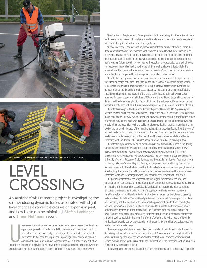
Strengthening ribs being cut by roadsaw (top) and fi lled with asphalt (top) and fi lled with asphalt (top) (this picture)
An Austrian/Swiss research project is investigating the stress-inducing dynamic forces associated with slight level changes as a vehicle crosses an expansion joint, and how these can be minimised. Stefan Lachinger and Simon Hoffmann report
The direct cost of replacement of an expansion joint in an existing structure is likely to be at least several times the cost of initial supply and installation, and the indirect costs associated with traffi c disruption are often even more signifi cant.
Surface unevenness at an expansion joint can result from a number of factors — from the design and fabrication of the expansion joint, from the installed level of the expansion joint relative to the adjacent road surface at each side, as designed and as constructed, and from deformations such as rutting in the asphalt road surfacing on either side of the joint due to traffi c loading. Deformation in service may be the result of, or exacerbated by, a lack of proper compaction of the road surfacing next to the joint during installation. Unfortunately this arises all too often because the expansion joint represents a ‘hard point’ in the surface which prevents it being compacted by any equipment that makes contact with it.
The effect of this dynamic loading on a structure or component whose design is based on static loading design principles — for example the wheel load of a stationary design vehicle — is represented by a dynamic amplifi cation factor. This is simply a factor which quantifi es the number of times the defl ections or stresses caused by the loading on a structure, if static, should be multiplied to take account of the fact that the loading is, in fact, dynamic. For example, if a beam supports a static load of 100kN, and the load is excited, making the loading dynamic with a dynamic amplication factor of 1.5, then it is no longer suffi cient to design the beam for a static load of 100kN; it must now be designed for an increased static load of 150kN.
The effect is recognised by European Technical Approval Guideline 032, Expansion joints for road bridges, which has been valid across Europe since 2013. This refers to the vehicle load model specifi ed by EN 1991-2, which contains an allowance for the dynamic amplifi cation effects of a vehicle moving on a road with good pavement conditions. In order to minimise dynamic effects within the expansion joint, the guideline also specifi es that the maximum deviation in level of the surface in the area of the joint, including adjacent road surfacing, from the level of an ideal, perfectly fl at connection line should not exceed 5mm, and that the maximum sudden level increase or decrease should not exceed 3mm. However, it does not state whether an expansion joint should ideally be installed above or below the adjacent driving surface.
The effect of dynamic loading on an expansion joint due to level differences in the driving surface has recently been investigated as part of a broader research programme known as EVAF (Development of wear-resistant expansion joints for bridges from the German Entwicklung Verschleissarmer Fahrbahnübergänge). The EVAF working group comprises the University of Natural Resources & Life Sciences and the Austrian Institute of Technology, both in Vienna, and manufacturer Mageba. Funding for the project was provided by the Austrian highways agency, Austrian Railways and the Austrian Federal Ministry for Transport, Innovation & Technology. The goal of the EVAF programme was to develop robust and low-maintenance expansion joints and technologies which allow repair or replacement with little effort.
The particular element of the programme to investigate the impact of the level and condition of the road surface on the joint’s durability and performance, and develop guidelines for reducing or minimising the associated dynamic loading, has recently been completed. It involved the development, using ANSYS, of a sophisticated fi nite element model of a variable longitudinal road level profi le in the vicinity of an expansion joint, being crossed by a standardised 40t vehicle. The road level profi le could be adjusted, for example, to simulate an expansion joint that was level with the connecting pavement, one that was 5mm higher, and one that was 5mm lower. It could also be adjusted to simulate the formation of a 5mm or 10mm-deep depression at the approach of the expansion joint, and similar depressions away from the edge of the joint, simulating targeted strengthening of otherwise deformable surfacing such as asphalt in this area. The effects of adjustments to the road profi le on the vertical loads experienced by the expansion joint under traffi c were then evaluated, enabling useful conclusions to be drawn.
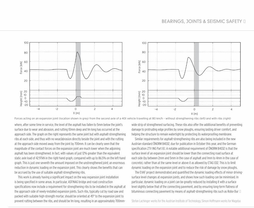
The graphs (opposite) show an example of the calculated distribution of contact forces on the driving surface in the vicinity of an expansion joint. On each graph, the longitudinal level profi le is shown by the line at the bottom and the contact forces from the vehicle’s critical second axle are shown by the curve at the top. The location of the expansion joint on all curves is indicated by the shaded column.
The graph on the left represents a joint with unstrengthened asphalt surfacing at each side,
LEVEL CROSSING
Bd&e | Issue 79 | 2015 www.bridgeweb.com 73
BeARINGs, JOINTs & seIsMIC sAFeTY n
where, after some time in service, the level of the asphalt has fallen to 5mm below the joint’s surface due to wear and abrasion, and rutting 10mm deep and 1m long has occurred at the approach side. The graph on the right represents the same joint but with asphalt-strengthening ribs at each side, and thus with no wear/abrasion directly beside the joint and with the rutting at the approach side moved away from the joint by 700mm. It can be clearly seen that the magnitude of the contact forces on the expansion joint are much lower when the adjoining asphalt has been strengthened. In fact, with values of just 12% greater than the equivalent static axle load of 42.97kN in the right-hand graph, compared with up to 86.5% on the left-hand graph. This is just one seventh the amount imposed on the unstrengthened joint; an enormous reduction in dynamic loading on the expansion joint. This clearly shows the benefits that can be accrued by the use of suitable asphalt-strengthening ribs.
This work is already having a significant impact on the way expansion joint installation is being specified in some areas. In particular, ASFINAG bridge and road construction specifications now include a requirement for strengthening ribs to be installed in the asphalt at the approach side of newly-installed expansion joints. Such ribs, typically cut by road saw and packed with suitable high-strength mortar, should be oriented at 45° to the expansion joint to prevent rutting between the ribs, and should be 1m long, resulting in an approximately 700mm-
wide strip of strengthened surfacing. These ribs also offer the additional benefits of preventing damage to protruding edge profiles by snow ploughs, ensuring lasting driver comfort, and helping the structure to remain watertight by protecting its waterproofing membrane.
Similar requirements for asphalt-strengthening ribs are also being included in the new Austrian standard ÖNORM B4032, due for publication in October this year, and the German specification ZTV ING Part 8.1. A notable additional requirement of ÖNORM B4032 is that the surface level of an expansion joint should be lower than the connecting road surface at each side (by between 2mm and 5mm in the case of asphalt and 1mm to 4mm in the case of concrete), rather than at the same level or above it as allowed by ETAG 032. This is to limit dynamic loading on the expansion joint and to reduce the risk of damage by snow ploughs.
The EVAF project demonstrated and quantified the dynamic loading effects of minor driving-surface level changes at expansion joints, and shows how such loading can be minimised. In particular, dynamic loading on a joint can be greatly reduced by installing it with a surface level slightly below that of the connecting pavement, and by ensuring long-term flatness of bituminous connecting pavement by means of asphalt-strengthening ribs such as Robo-Dur n
Stefan Lachinger works for the Austrian Institute of Technology, Simon Hoffmann works for Mageba
100
80
60
40
20
2010 0–10–20H
eigh
t [m
m]
Forc
e [k
N]
–4 –2 0 2 4X [m]
100
80
60
40
20
2010 0–10–20
Forc
e [k
N]
–4 –2 0 2 4
X [m]
Hei
ght
[mm
]
Forces acting on an expansion joint (location shown in grey) from the second axle of a 40t vehicle travelling at 80 km/h – without strengthening ribs (left) and with ribs (right)
Bridge bearingsSeismic protectionBridge expansion joints
IDEAS, ENGINEERING AND MANUFACTUREIDEAS, ENGINEERING AND MANUFACTUREAgom International srl - Via Mesero, 12 - 20010 - Ossona - (MI) -Italy - www.agom.it - [email protected] - Tel +(39) 029029111- Fax +(39) 029010201
Kå�
ord
bru
a -
No
rway