level product catalog chp 1 - mts sensors sensors level plus® liquid-level sensors, product...
TRANSCRIPT

Level Plus®
Magnetostrictive Liquid-Level Sensors
with Temposonics® Technology
Product Accessories
Floats, Weights, Meters, Enclosures, Indicators,Interface Terminals and Programming
SENSORS
®
Document Part Number551103 Revision E
All specifications are subject to change. Contact MTS for specifications and engineering drawings that are critical to your application. Drawings contained in this document are for reference only. Go to www.mtssensors.com for the latest support documentation.
FMAPPROVED
FEAtuREs
� Variety of styles and sizes to Fit Most Applications � Available in 316L stainless steel, Aluminum, teflon®,
Hastelloy® C and Nitrophyl® � Custom Weighting Available
APPLiCAtioNs
� Custody transfer � inventory Control � Bulk storage � sanitary Process Control
MARkEts
� Petroleum and Petrochemical � LPG terminals � Biotech and Pharmaceutical � Food and Beverage � Waste and Wastewater
Mts offers a Variety of M-series Liquid-Level ProductAccessories
Accessories overview
MTS Sensors offers a variety of floats to meet your application needs. Our floats come in a variety of sizes from less than 38 mm (1.5 in.) up to 178 mm (7 in.) in diameter. Float materials are available in stainless steel, Teflon®, Aluminum, Hastelloy® C and Nitrophyl®.
Offset weighted floats are also available for applications requiring ATEX approval. Product viscosity, specific gravity, and temperature can vary widely in a process or tank gauging application. Because of these variables and others, such as tank pressure and corrosiveness, no one float can meet all requirements. Therefore, a variety of float styles are available and we will assist you in choosing the one that best meets your requirements.
When choosing a float for your application, MTS recommends you choose one that has a specific gravity of at least 0.05 less than that of the measured liquid. For interface measurement, a minimum of 0.05 specific gravity differential is recommended between upper and lower liquids.
MTS Sensors also offers a variety of meters, housings, and calibration equipment as accessories to our transmitter range. Meters are avail-able for analog, DDA, and Modbus outputs.
For more information, please contact the MTS Sensors’ applications department or go to www.mtssensors.com for more information.

MTS SensorsLevel Plus® Liquid-Level Sensors, Product Accessories CatalogPart Number: 551103 Revision E 10/11 EN
standard Float options
General Notes:
1. Be sure that the float specific gravity is at least 0.05 less than that of the measured liquid as a safety margin at ambient temperature.
2. For interface measurement: A minimum of 0.05 specific gravity differential is required between the upper and lower liquids.
3. When the magnet is not shown, the magnet is positioned at the center line of float.
4. Offset weight option: A weight is installed in the float to bias, or tilt, the float installed on the transmitter tube so that the float remains in contact with the transmitter tube at all times. The offset option is required for installations that must conform to ATEX standards.
5. Drawings contained in this document are for reference only. Contact the factory for engineering drawings.
6. *Call for specific lead times. Typical lead time exceeds lead time of the transmitter.
stANDARD PRoDuCt FLoAtsFloat and dimension reference Pressure temp.
Magnetoffset
specificgravity Material
Weight offset Part number
18 mm(0.7 in.) dia.
47 mm(1.85 in.) dia.
77 mm(3.01 in.) 29.3 bar
(425 psi)149 °C
(300 °F) No
0.65 SS No 251981-1
0.67 SS Yes 251981-2*
0.68 Hastelloy C No 251981-3
0.71 Hastelloy C Yes 251981-4*
18 mm (0.7 in.) dia.
57 mm(2.22 in.)
59 mm (2.32 in.) dia.
22.4 bar(325 psi)
149 °C(300 °F) No
0.48 SS No 251387-1
0.48 SS Yes 251387-2*
18 mm (0.7 in.) dia.
36 mm(1.4 in.)
41 mm (1.61 in.) dia.
8.6 bar(125 psi)
149 °C(300 °F) No
0.74 SS No 200938-1
0.74 SS Yes 200938-2*
50 mm(1.95 in.)
55 mm (2.14 in.) dia.
18 mm (0.7 in.) dia.
51.7 bar(750 psi)
149 °C(300 °F) No 0.74 SS No 252354*
18 mm (0.7 in.) dia.
50 mm(1.96 in.)
47 mm(1.83 in.) dia.
54 mm(2.11 in.) 4 bar
(60 psi)149 °C
(300 °F) Yes 0.6 SS Yes 201605-2
45 mm(1.75 in.) dia.
18 mm(0.70 in.) Min. ID
67 mm(2.60 in.)
79 mm(3.1 in.)Max.
29.3 bar(425 psi)
149 °C(300 °F) Yes
0.45 Aluminum No 201693-1
0.45 Aluminum Yes 201693-2
2

MTS SensorsLevel Plus® Liquid-Level Sensors, Product Accessories Catalog
Part Number: 551103 Revision E 10/11 EN
standard Float options
LoW-LiFtoFF FLoAtFloat and dimension reference Pressure temp.
Magnetoffset
specificgravity Material
Weight offset Part number
26 mm(1 in.)
76 mm(3 in.)
18 mm (0.7 in.) I.D. min. 101 mm
(3.95 in.) O.D.
39 mm(1.52 in.)
Magnet
38 mm(1.5 in.)
15 mm(0.57 in.) Ref
8.6 bar(125 psi)
149 °C(300 °F) Yes 0.65 SS No 252228-3*
stANDARD iNtERFACE FLoAtsFloat and dimension reference Pressure temp.
Magnetoffset
specificgravity Material
Weight offset Part number
18 mm(0.7 in.) dia.
47 mm(1.85 in.) dia.
77 mm(3.01 in.) 29.3 bar
(425 psi)149 °C
(300 °F) No 0.90 -0.96
SSNo 251982-1
Yes 251982-2*
Hastelloy C
No 251982-3
Yes 251982-4*
18 mm(0.7 in.) dia.
47 mm(1.85 in.) dia.
77 mm(3.01 in.) 29.3 bar
(425 psi)149 °C
(300 °F) No 1.03 -1.10
SS
No 251983-1
Yes 251983-2*
Hastelloy C
No 251983-3*
Yes 251983-4*
18 mm(0.7 in.) dia.
31 mm(1.22 in.)27 mm
(1.06 in.)
47 mm
(1.83 in.) dia.
4 bar(60 psi)
149 °C(300 °F) Yes 0.85 -
0.9 SS Yes 201606-2
stANDARD PRoDuCt FLoAtsFloat and dimension reference Pressure temp.
Magnetoffset
specificgravity Material
Weight offset Part number
18 mm (0.7 in.) dia.
89 mm (3.5 in.) dia.
91 mm(3.57 in.) 29.3 bar
(425 psi)149 °C
(300 °F) No
0.43 SS No 251469-1
0.45 SS Yes 251469-2*
3

MTS SensorsLevel Plus® Liquid-Level Sensors, Product Accessories CatalogPart Number: 551103 Revision E 10/11 EN
sanitary Float options
General Notes (for sanitary applications):
1. Be sure that the float specific gravity is at least 0.05 less than that of the measured liquid as a safety margin at ambient temperature.
2. For interface measurement: A minimum of 0.05 specific gravity differential is required between the upper and lower liquids.
3. Sanitary polish is available for stainless-steel floats up to 200 Grit/Ra 25.
4. Electropolish is available for stainless-steel floats up to 240 Grit/Ra 15.
5. When the magnet is not shown, the magnet is positioned at the center line of float.
6. Offset weight option: A weight is installed in the float to bias, or tilt, the float installed on the transmitter tube so that the float remains in contact with the transmitter tube at all times. The offset option is required for installations that must conform to ATEX standards.
7. Drawings contained in this document are for reference only. Contact the factory for engineering drawings.
8. *Call for specific lead times. Typical lead time exceeds lead time of the transmitter.
Notes:
1. Float meets 3A Sanitary specifications.
2. Use this float with all Sanitary transmitter wells as other floats may enter the inactive zone when the tank is emptied.
sANitARy FLoAtsFloat and dimension reference Pressure temp.
Magnetoffset
specificgravity Material
Weight offset Part number
18 mm(0.7 in.) dia.
47 mm(1.85 in.) dia.
Centerline of magnet
89 mm(3.5 in.)
108 mm(4.25 in.)
10.3 bar(150 psi)
149 °C(300 °F) Yes 0.66
SS200 Grit/Ra 25 μm
(0.625 μm)
No 401513-1
Yes 401513-2*
SS240 Grit/Ra 15 μm
(0.375 μm)
No 401513-3*
Yes 401513-4*
Notes:
1. Float meets 3A Sanitary specifications.
2. Float may enter the inactive zone when used with 3A Sanitary transmitter wells.
Float and dimension reference Pressure temp.Magnetoffset
specificgravity Material
Weight offset Part number
22.4 bar(325 psi)
149 °C(300 °F) No 0.63
SS200 Grit/
Ra 25 μm (0.625 μm)
No 200931-1*
Yes 200931-2*
SS240 Grit/
Ra 15 μm (0.375 μm)
No 200931-3*
Yes 200931-4*
22.4 bar(325 psi)
149 °C(300 °F) Yes 0.63
SS200 Grit/Ra 25 μm
(0.625 μm)
No 200931-5*
Yes 200931-6*
SS240 Grit/
Ra 15
No 200931-7*
Yes 200931-8*
18 mm(0.7 in.) dia.
60 mm(2.34 in.) dia.
75 mm(2.95 in.)
38 mm(1.5 in.)
CL64 mm(2.5 in.)
CL of magnet withMagnet Offset
4

MTS SensorsLevel Plus® Liquid-Level Sensors, Product Accessories Catalog
Part Number: 551103 Revision E 10/11 EN
sanitary Float options
Note:
Use this float with all Sanitary transmitter wells as other floats may enter the inactive zone when the tank is emptied.
sANitARy FLoAts CoNtiNuEDFloat and dimension reference Pressure temp.
Magnetoffset
specificgravity Material
Weight offset Part number
51 mm(2 in.) dia.
Over weld bead
Magnet
25 mm(.98 in.)
48 mm(1.9 in.)
102 mm(4.02 in.)
41 mm(1.6 in.)
18 mm(.7 in.) I.D.Min.92 mm
(3.6 in.) dia.
8.6 bar(125 psi)
149 °C(300 °F) Yes 048
SS240 Grit/Ra 15 μm
(0.375 μm )
No 252228-1*
Notes:
1. Float meets clean-in-place and drain-in-place applications.
2. Float may enter the inactive zone. Consult factory about viability of usage.
Float and dimension reference Pressure temp.Magnetoffset
specificgravity Material
Weight offset Part number
Magnet
18 mm(0.7 in.)Min I.D.
25 mm (.98 in.)51 mm
(2 in.) O.D.Over weld bead
50 mm (1.96 in.) 22.4 bar(325 psi)
149 °C(300 °F) No 0.74
SS240 Grit/Ra 25 μm
(0.625 μm )
No 251234-1*
Yes 251234-2*
Notes:
1. Float meets 3A Sanitary specifications.
2. Float meets clean-in-place and drain-in-place applications.
3. Float may enter the inactive zone. Consult factory about viability of usage.
Float and dimension reference Pressure temp.Magnetoffset
specificgravity Material
Weight offset Part number
Magnetposition
L
73 mm(2.85 in.) dia.
C
56 mm(2.21 in.)
80 mm(3.15 in.) dia.
R.157 (4) Min.
23 mm(.9 in.) dia.
8.6 bar(125 psi)
149 °C(300 °F) Yes 0.83 -
0.86
SS240 Grit/Ra 15 μm
(0.375 μm )
Yes 560564-2*
5
MTS SensorsLevel Plus® Liquid-Level Sensors, Product Accessories CatalogPart Number: 551103 Revision E 10/11 EN
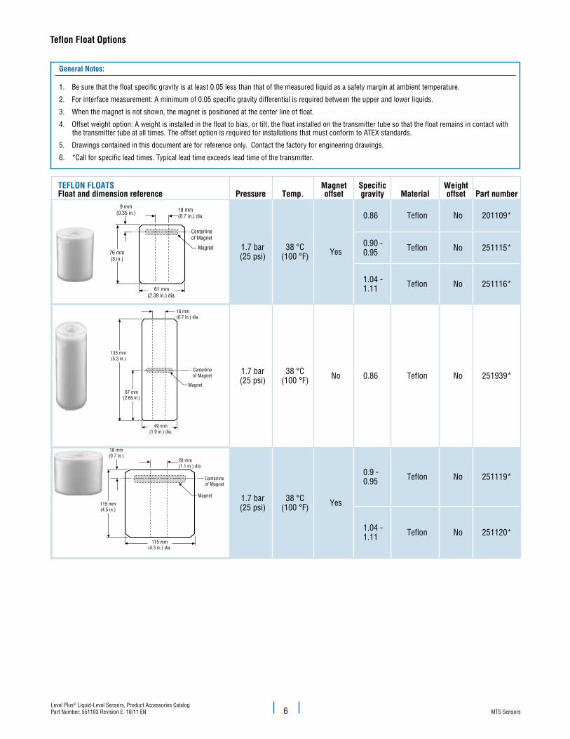
teflon Float options
61 mm(2.38 in.) dia.
76 mm(3 in.)
9 mm(0.35 in.)
Magnet
Centerlineof Magnet
18 mm(0.7 in.) dia.
67 mm(2.65 in.)
49 mm(1.9 in.) dia.
Magnet
Centerlineof Magnet
18 mm(0.7 in.) dia.
135 mm(5.3 in.)
115 mm(4.5 in.) dia.
115 mm(4.5 in.)
18 mm(0.7 in.)
Magnet
Centerlineof Magnet
28 mm(1.1 in.) dia.
tEFLoN FLoAtsFloat and dimension reference Pressure temp.
Magnetoffset
specificgravity Material
Weight offset Part number
1.7 bar(25 psi)
38 °C(100 °F) Yes
0.86 Teflon No 201109*
0.90 -0.95 Teflon No 251115*
1.04 -1.11 Teflon No 251116*
1.7 bar(25 psi)
38 °C(100 °F) No 0.86 Teflon No 251939*
1.7 bar(25 psi)
38 °C(100 °F) Yes
0.9 - 0.95 Teflon No 251119*
1.04 - 1.11 Teflon No 251120*
General Notes:
1. Be sure that the float specific gravity is at least 0.05 less than that of the measured liquid as a safety margin at ambient temperature.
2. For interface measurement: A minimum of 0.05 specific gravity differential is required between the upper and lower liquids.
3. When the magnet is not shown, the magnet is positioned at the center line of float.
4. Offset weight option: A weight is installed in the float to bias, or tilt, the float installed on the transmitter tube so that the float remains in contact with the transmitter tube at all times. The offset option is required for installations that must conform to ATEX standards.
5. Drawings contained in this document are for reference only. Contact the factory for engineering drawings.
6. *Call for specific lead times. Typical lead time exceeds lead time of the transmitter.
61 mm(2.38 in.) dia.
76 mm(3 in.)
9 mm(0.35 in.)
Magnet
Centerlineof Magnet
18 mm(0.7 in.) dia.
67 mm(2.65 in.)
49 mm(1.9 in.) dia.
Magnet
Centerlineof Magnet
18 mm(0.7 in.) dia.
135 mm(5.3 in.)
115 mm(4.5 in.) dia.
115 mm(4.5 in.)
18 mm(0.7 in.)
Magnet
Centerlineof Magnet
28 mm(1.1 in.) dia.
6
MTS SensorsLevel Plus® Liquid-Level Sensors, Product Accessories Catalog
Part Number: 551103 Revision E 10/11 EN
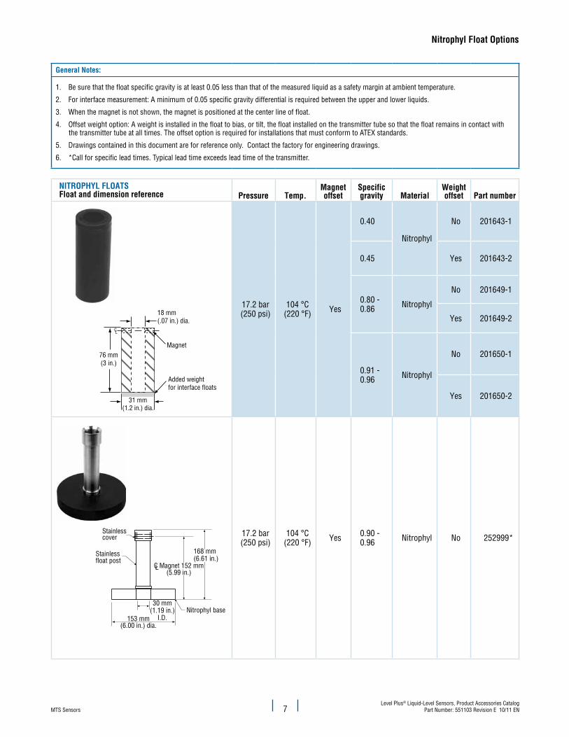
Nitrophyl Float options
General Notes:
1. Be sure that the float specific gravity is at least 0.05 less than that of the measured liquid as a safety margin at ambient temperature.
2. For interface measurement: A minimum of 0.05 specific gravity differential is required between the upper and lower liquids.
3. When the magnet is not shown, the magnet is positioned at the center line of float.
4. Offset weight option: A weight is installed in the float to bias, or tilt, the float installed on the transmitter tube so that the float remains in contact with the transmitter tube at all times. The offset option is required for installations that must conform to ATEX standards.
5. Drawings contained in this document are for reference only. Contact the factory for engineering drawings.
6. *Call for specific lead times. Typical lead time exceeds lead time of the transmitter.
NitRoPHyL FLoAtsFloat and dimension reference Pressure temp.
Magnetoffset
specificgravity Material
Weight offset Part number
18 mm(.07 in.) dia.
Magnet
CL
76 mm(3 in.)
31 mm(1.2 in.) dia.
Added weightfor interface floats
17.2 bar(250 psi)
104 °C(220 °F) Yes
0.40
Nitrophyl
No 201643-1
0.45 Yes 201643-2
0.80 - 0.86 Nitrophyl
No 201649-1
Yes 201649-2
0.91 - 0.96 Nitrophyl
No 201650-1
Yes 201650-2
Stainlesscover
Stainlessfloat post
Nitrophyl base
168 mm(6.61 in.)
C Magnet 152 mm(5.99 in.)
153 mm(6.00 in.) dia.
30 mm(1.19 in.)
I.D.
L
17.2 bar(250 psi)
104 °C(220 °F) Yes 0.90 -
0.96 Nitrophyl No 252999*
7

MTS SensorsLevel Plus® Liquid-Level Sensors, Product Accessories CatalogPart Number: 551103 Revision E 10/11 EN
Long-gauge Float options
General Notes:
1. Be sure that the float specific gravity is at least 0.05 less than that of the measured liquid as a safety margin at ambient temperature.
2. For interface measurement: A minimum of 0.05 specific gravity differential is required between the upper and lower liquids.
3. When the magnet is not shown, the magnet is positioned at the center line of float.
4. Offset weight option: A weight is installed in the float to bias, or tilt, the float installed on the transmitter tube so that the float remains in contact with the transmitter tube at all times. The offset option is required for installations that must conform to ATEX standards.
5. Drawings contained in this document are for reference only. Contact the factory for engineering drawings.
6. *Call for specific lead times. Typical lead time exceeds lead time of the transmitter.
LoNG-GAuGE FLoAtsFloat and dimension reference Pressure temp.
Magnetoffset
specificgravity Material
Weight offset Part number
LC Magnet
88 mm(3.44 in.)
44 mm(1.72 in.)
28 mm(1.1 in.)dia.
92 mm(3.6 in.) dia.
29.3 bar(425 psi)
149 °C (300 °F) No
0.54 SS No 251223-1
0.65 Hastelloy C No 251223-3*
0.90 -0.96
SS No 251224-1
Hastelloy C No 251224-3*
1.03 -1.10
SS No 251225-1*
Hastelloy C No 251225-3*
L
92 mm(3.6 in.) dia.
76 mm(3 in.)
88 mm(3.44 in.)
C Magnet
28 mm(1.1 in.)dia.
29.3 bar(425 psi)
149 °C (300 °F) Yes
0.54 SSNo 252961-1
Yes 252961-2*
0.90 -0.96 SS
No 252962-1
Yes 252962-2*
1.03 -1.10 SS
No 252963-1*
Yes 252963-2*
C
Magnet
L
127 mm(4.98 in.)
63 mm(2.49 in.)
28 mm(1.1 in.) dia.130 mm
(5.11 in.)
37.9 bar(550 psi)
149 °C(300 °F) No
0.44 SS No 250709-1*
0.52 Hastelloy C No 250709-3*
0.90 -0.96
SS No 250714-1*
Hastelloy C No 250714-3*
1.03 -1.10
SS No 250855-1*
Hastelloy C No 250855-3*
8

MTS SensorsLevel Plus® Liquid-Level Sensors, Product Accessories Catalog
Part Number: 551103 Revision E 10/11 EN
Long-gauge Float options
LoNG-GAuGE FLoAts (CoNtiNuED)Float and dimension reference Pressure temp.
Magnetoffset
specificgravity Material
Weight offset Part number
130 mm(5.11 in.)
127 mm(4.98 in.)
116 mm(4.55 in.)
28 mm (1.1 in.)
CL Magnet
37.9 bar(550 psi)
149 °C (300 °F) Yes
0.44
SS
No 201248-1
0.44 Yes 201248-2*
0.90 - 0.96 SS
No 252959-1
Yes 252959-2*
1.03 - 1.10 SS
No 252960-1*
Yes 252960-2*
48 mm(1.9 in.)
I.D.
6.95 in.(00.0 mm)
178 mm(7 in.)
178 mm (7 in.)
17.2 bar(250 psi)
149 °C(300 °F) No
0.44 SSNo 251426-1*
Yes 251426-2*
0.47 Hastelloy C-22
No 251426-3*
Yes 251426-4*
0.90 -0.96
SSNo 251427-1*
Yes 251427-2*
Hastelloy C-22
No 251427-3*
Yes 251427-4*
1.03 -1.10 SS
No 251428-1*
Yes 251428-2*
28 mm(1.1 in.) dia.
127 mm(5.01 in.)
70 mm(2.76 in.) max. dia.
22.4 bar(325 psi)
149 °C(300 °F) No
0.66 SS
No 201232-1
Yes 201232-2*
0.70 Hastelloy C
No 201232-3*
Yes 201232-4*
0.92 -0.96 SS
No 201233-1*
Yes 201233-2*
9

MTS SensorsLevel Plus® Liquid-Level Sensors, Product Accessories CatalogPart Number: 551103 Revision E 10/11 EN
Process Meters and Enclosure options
ANALoG PRoCEss MEtERs Part number
LED Display universal Analog Process MeterPrecision Digital PD6000-6R06 Digit LED displayinput: Analog 4-20 mAoutput: None110 VAC Input Power32 point linearizationIncludes 24 Vdc transmitter supplyMaterial:Standard 1/8 in. DIN, high impact plastic, NEMA Type 4X front panel
380071
LED Display universal Analog Process Meter (2 Relays)Precision Digital PD6000-6R26 Digit LED displayinput: Analog 4-20 mAoutput: 2 relays110 VAC Input Power32 point linearizationIncludes 24 Vdc transmitter supplyMaterial:Standard 1/8 in. DIN, high impact plastic, NEMA Type 4X front panel
380072
LED Display universal Analog Process Meter (4 Relays)Precision Digital PD6000-6R46 Digit LED displayinput: Analog 4-20 mAoutput: 4 relays110 VAC Input Power32 point linearizationIncludes 24 Vdc transmitter supplyMaterial:Standard 1/8 in. DIN, high impact plastic, NEMA Type 4X front panel
380073
LED Display universal Analog Process Meter (2 Relays, 4-20 mA)Precision Digital PD6000-6R56 Digit LED displayinput: Analog 4-20 mAoutput: 4-20 mA and 2 relays110 VAC Input Power32 point linearizationIncludes 24 Vdc transmitter supplyMaterial:Standard 1/8 in. DIN, high impact plastic, NEMA Type 4X front panel
380095
XP Loop Powered Analog Meter Loop Powered on 4-20 mA outputDisplays in Percentage OnlyEmbedded in XP HousingXP: Class I, II, III; Division 1; Groups B-Gis: Class I, II, III; Division 1; Groups A-G
380062
Loop Powered Analog Meter F070-A-HG-PL-X1-ZBLoop Powered on 4-20 mA outputDisplays loop current, engineering units, and/or valueSelectable on screen engineering unitsIP 67 / NEMA Type 4XIntrinsically Safe, backlight
380088
10

MTS SensorsLevel Plus® Liquid-Level Sensors, Product Accessories Catalog
Part Number: 551103 Revision E 10/11 EN
Process Meters and Enclosure options
ANALoG PRoCEss MEtERs (CoNtiNuED) Part number
Multi-Channel Consolidating Analog Process MeterPrecision Digital PD941-8K9-15input: 4 Analog 4-20 mAoutput: 4 Analog 4-20 mA, 9 relays110 VAC Input Power32 point linearization
380089
MoDBus PRoCEss MEtERs Part number
Multivariable Modbus Process MeterDisplay levels in feet, inches, and 16ths of an inchScrolling Display of Product, Interface, Temperature, or combinationinput: RS485 Modbus RTUoutput: 2 Form A relays and 4-20 mA110 VAC Input Power16 point linearizationIncludes 24 Vdc transmitter supplyMaterial:Standard 1/8 in. DIN, high impact plastic, NEMA Type 4X front panel
380086
single Variable Modbus Process Meter Precision Digital PD865-6R5-166 Digit Display in Decimal FormatDisplay 1 process variable without interrupting Master/Slave communicationinput: RS485 Modbus RTUoutput: 2 Form A relays and 4-20 mA110 VAC Input Power16 point linearizationIncludes 24 Vdc transmitter supplyMaterial: Standard 1/8 in. DIN, high impact plastic, NEMA Type 4X front panel
380094
11

MTS SensorsLevel Plus® Liquid-Level Sensors, Product Accessories CatalogPart Number: 551103 Revision E 10/11 EN
Process Meters and Enclosure options
PRoCEss MEtER ENCLosuREs Part number
XP Enclosures••Display 380086 or 380094Display 380088•• XP Enclosures are available for most process meters, please contact factory for more information.
561452561453
NEMA Enclosures†
single NEMA 4X (PDA 2811)Dual NEMA 4X(PDA 2302)† NEMA Enclosures are available for most process meters, please contact factory for more information.
401150
401151
MoDBus tERMiNALs Part number
LCD Modbus terminalDisplays up to 4 tanks (2 levels, temp, volume)Displays up to 8 tanks (2 levels, temp)Displays levels in ft., in, and 16ths in.input: Up to 8 Modbus transmittersoutput: ModbusMounted in NEMA 4 boxClass 1 Div. 2Includes Power SupplyCalibrate from Screen
280494-X
touchscreen Modbus terminalDisplays up to 16 tanks (2 levels, temp, volume)Displays levels in ft., in, and 16ths in.input: up to 16 Modbus transmittersoutput: ModbusPictorial display of tanksTouchscreenMounted in NEMA 4 boxClass 1 Div. 2Includes Power SupplyCalibrate from Screen
280508
12

MTS SensorsLevel Plus® Liquid-Level Sensors, Product Accessories Catalog
Part Number: 551103 Revision E 10/11 EN
Programming and Hardware options
PRoGRAMMiNG ACCEssoRiEs Part number
Ht100 Hand Held terminalM-Series Model MG Transmitter with DDA outputRemote setup, troubleshooting, and maintenance
251259
sEtuP soFtWARE Part numberM-series Model MGPC setup software on CDIncludes RS-485 to RS-232 adapter, part no. 380077
625051
M-series Model MGPC setup software on CD 625052
M-series Model MRPC setup software on CDIncludes HART adapter, part no. 380068
252273-1
M-series Model MRPC setup software on CD 252273-2
HARDWARE Part numberHARt to Rs-232 adapter(SMAR H1-311) 380068
RS-485 to RS-232 adapter converter(B & B Electronics) 380077
Hex Bushing2 in. MNPT x 3/4 in. FNPT 561440
Hex Bushing2 in. FNPT x 4 in. MNPT 561441
Hex Bushing1 in. FNPT x 2 in. MNPT 561448
13

MTS SensorsLevel Plus® Liquid-Level Sensors, Product Accessories CatalogPart Number: 551103 Revision E 10/11 EN
Magnet and Weight Assembly options
MAGNEt AND WEiGHt AssEMBLiEs Part number
51 mm(2 in.)
76 mm(3 in.)
150 lb. Pull MagnetFor LDF long transmitter and M-Series transmitters. (Top ring must be removed before installa-tion)
560604
51 mm(2 in.)
127 mm(5 in.)
standard 11 lb. WeightFor M-Series transmitters 401059
A
A
193 mm(7.5 in.) dia.
165 mm(6.5 in.) dia.
Section A-A
84 mm(3.3 in.) 3 mm
( .13 in.)16 mm( .63 in.)
Low Liftoff 11 lb. Weight AssemblyUse with float, part no. 252999
402364
89 mm (3.5 in.) dia.
32 mm (1.25 in.)dia. (2X)
37 mm(1.44 in.)
115 mm(4.5 in.)
64 mm(2.5 in.)
21 mm(.81 in.) dia.
1.3 X 45˚Chamfer
Narrow 11 lb. WeightUse with M-Series transmitters 402647
14

MTS SensorsLevel Plus® Liquid-Level Sensors, Product Accessories Catalog
Part Number: 551103 Revision E 10/11 EN15

MTS Systems CorporationSensors Division
3001 Sheldon DriveCary, North Carolina27513, USATel.: +1-800-633-7609Fax: +1-919-677-2343 +1-800-498-4442e-mail: [email protected]://www.mtssensors.com
MTS Sensor TechnologieGmbH & Co. KG
Auf dem Schüffel 9D - 58513 Lüdenscheid, GermanyTel.: +49-2351-9587-0Fax: +49-2351-56491e-mail: [email protected]://www.mtssensor.de
MTS Sensors TechnologyCorporation
737 Aihara-cho, Machida-shiTokyo 194-0211, JapanTel.: +81-42-775-3838Fax: +81-42-775-5516e-mail: [email protected]://www.mtssensor.co.jp
SENSORS
®
Document Part Number: 551103 Revision E 10/11 EN
MTS, Temposonics and Level Plus are registered trademarks of MTS Systems Corporation. All other trademarks are the property of their respective owners. Printed in USA. Copyright © 2011 MTS Systems Corporation. All Rights Reserved in all media.
All specifications are subject to change. Contact MTS for specifications and engineering drawings that are critical to your application. Drawings contained in this document are for reference only. Go to http://www.mtssensors.com for the latest support documentation and related media.