level product catalog chp 1 - mts sensors
TRANSCRIPT
All specifications are subject to change. Contact MTS for specifications and engineering drawings that are critical to your application. Drawings contained in this document are for reference only. Go to http://www.mtssensors.com for the latest support documentation and related media.
Level Plus®
Magnetostrictive Liquid-Level Sensors
with Temposonics® Technology
M-Series Model MGTransmitter with Digital Output
Data Sheet
SENSORS
®
Document Part Number550784 Revision J
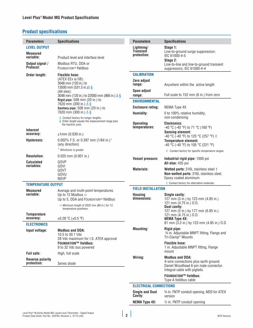
Model MG Rigid TransmitterSingle-Cavity Housing
Model MG Sanitary TransmitterNEMA Type 4X Enclosure
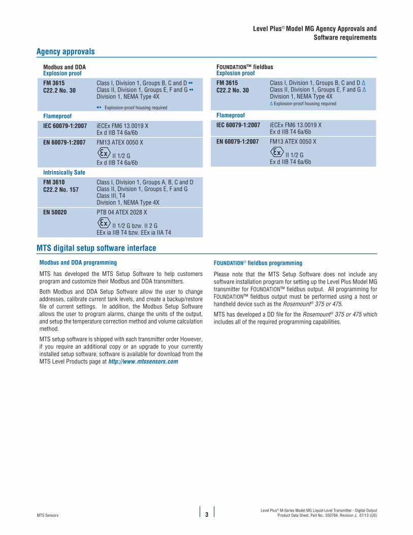
Model MG Flexible TransmitterDual-Cavity Housing
FEATURES
� Modbus and FOUNDATION™ fieldbus Output � 3-in-1 Measurement
• Product • Interface • Temperature
� 100 point Strap Table � No Scheduled Maintenance or Recalibration � API Temperature Corrected Volumes � Inherent Accuracy ±1mm � Explosion-proof and/or Intrinsically Safe
APPLICATIONS
� Custody Transfer � Inventory Control � Bulk Storage � Sanitary Process Control
MARKETS
� Petroleum and Petrochemical � LPG Terminals � Biotech and Pharmaceuticals � Food and Beverage � Water and Wastewater
Product overview
The Level Plus® M-Series Model MG level transmitter satisfies the de-mand for a digital communication interface that offers the liquid-level marketplace unsurpassed flexibility to meet most process application conditions. The Level Plus Model MG transmitter provides 3-in-1 measurement using one process opening for product level, interface level, and temperature measurements. Once the transmitter is installed and calibrated there is no requirement for scheduled maintenance or recalibration. Set it and forget it!
Level Plus Model MG transmitters are modular in design, offering you a selection of electronic housing styles, transmitter pipe styles and wetted materials. The Level Plus Model MG transmitter features a removable sensing element and can also incorporate 1, 5, or 12 temperature measurement points depending on the output. Subject to local electrical codes, the sensing element and electronics housing can be removed from the transmitter pipe without disrupting the operation of your process saving you time and money.
Outputs for the Level Plus Model MG transmitter include Modbus, FOUNDATION™ fieldbus, and DDA (a proprietary ASCII protocol). Modbus and DDA outputs are communicated via a 4-wire multi-drop power and data bus (EIA 485), whereas FOUNDATION™ fieldbus has a specified 3-wire bus. Utilizing the bus network eliminates the requirements for individual cable runs from each tank and these three data formats provide a direct interface to most types of computers and digital communication equipment. Both Modbus and FOUNDATION™ fieldbus outputs also allow a user to measure volume from a 100 point strap table with the option for temperature correction.
FMAPPROVED
Level Plus® M-Series Model MG Liquid-Level Transmitter - Digital OutputProduct Data Sheet, Part No.: 550784, Revision J, 07/13 (US) MTS Sensors2
Parameters Specifications
LEVEL OUTPUT
Measured variable: Product level and interface level
Output signal /Protocol:
Modbus RTU, DDA or FOUNDATION™ fieldbus
Order length: Flexible hose:(ATEX EEx ia IIB):3048 mm (120 in.) to 13500 mm (531.5 in.)∆ §(All else):3048 mm (120 in.) to 22000 mm (866 in.) ∆ §Rigid pipe: 508 mm (20 in.) to 7620 mm (300 in.) ∆ §Sanitary pipe: 508 mm (20 in.) to 7620 mm (300 in.) ∆ §
∆ Contact factory for longer lengths.§ Order length equals the measurement range plus
the inactive zone.
Inherent accuracy: ±1mm (0.039 in.) Hysteresis: 0.002% F.S. or 0.397 mm (1/64 in.)*
(any direction) * Whichever is greater
Resolution: 0.025 mm (0.001 in.)
Calculated variables:
GOVPGOVIGOVTGOVUNSVP
TEMPERATURE OUTPUT
Measured variable:
Average and multi-point temperatures Up to 12 Modbus ∞Up to 5, DDA and FOUNDATION™ fieldbus
∞ Minimum length of 2032 mm (80 in.) for 12 temperature positions.
Temperature accuracy: ±0.28 ºC (±0.5 ºF)
ELECTRONICS
Input voltage: Modbus and DDA:10.5 to 30.1 Vdc28 Vdc maximum for I.S. ATEX approval FOUNDATION™ fieldbus: 9 to 32 Vdc bus powered
Fail safe: High, full scale
Reverse polarity protection: Series diode
Parameters Specifications
Lightning/Transient protection:
Stage 1: Line-to-ground surge suppression; IEC 61000-4-5Stage 2: Line-to-line and line-to-ground transient suppressors; IEC 61000-4-4
CALIBRATION
Zero adjust range: Anywhere within the active length
Span adjust range: Full scale to 152 mm (6 in.) from zero
ENVIRONMENTAL
Enclosure rating: NEMA Type 4X
Humidity: 0 to 100% relative humidity, non-condensing
Operating temperatures:
Electronics: -40 °C (-40 °F) to 71 °C (160 ºF) Sensing element: -40 °C (-40 °F) to 125 °C (257 °F) ◊Temperature element: -40 °C (-40 °F) to 105 °C (221 °F)
◊ Contact factory for specific temperature ranges.
Vessel pressure: Industrial rigid pipe: 1000 psiAll else: 435 psi
Materials: Wetted parts: 316L stainless steel †Non-wetted parts: 316L stainless steel, Epoxy coated aluminum
† Contact factory for alternative materials.
FIELD INSTALLATION
Housing dimensions:
Single cavity:127 mm (5 in.) by 123 mm (4.85 in.)121 mm (4.75 in.) O.D.Dual cavity:127 mm (5 in.) by 177 mm (6.95 in.)121 mm (4.75 in.) O.D.NEMA Type 4X:81 mm (3.2 in.) by 123 mm (4.85 in.) O.D.
Mounting: Rigid pipe: ¾ in. Adjustable MNPT fitting, Flange and Tri-Clamp® Mounts
Flexible hose: 1 in. Adjustable MNPT fitting, Flange mount
Wiring: Modbus and DDA:4-wire connections plus earth ground.Daniel Woodhead 6-pin male connector.Integral cable with pigtails.
FOUNDATION™ fieldbus: Type A fieldbus cable
ELECTRICAL CONNECTIONS
Single and Dual Cavity:
¾ in. FNTP conduit opening, M20 for ATEX version
NEMA Type 4X: ½ in. FNTP conduit opening
Product specifications
Level Plus® Model MG Product Specifications
Level Plus® M-Series Model MG Liquid-Level Transmitter - Digital OutputProduct Data Sheet, Part No.: 550784, Revision J, 07/13 (US)MTS Sensors 3
Agency approvals
MTS digital setup software interface
Modbus and DDAExplosion proof
FM 3615C22.2 No. 30
Class I, Division 1, Groups B, C and D ••Class II, Division 1, Groups E, F and G ••Division 1, NEMA Type 4X
•• Explosion-proof housing required
Flameproof
IEC 60079-1:2007 iECEx FM6 13.0019 XEx d IIB T4 6a/6b
EN 60079-1:2007 FM13 ATEX 0050 X
II 1/2 GEx d IIB T4 6a/6b
Intrinsically Safe
FM 3610C22.2 No. 157
Class I, Division 1, Groups A, B, C and DClass II, Division 1, Groups E, F and GClass III, T4Division 1, NEMA Type 4X
EN 50020 PTB 04 ATEX 2028 X
II 1/2 G bzw. II 2 GEEx ia IIB T4 bzw. EEx ia IIA T4
FOUNDATION™ fieldbusExplosion proof
FM 3615C22.2 No. 30
Class I, Division 1, Groups B, C and D ∆Class II, Division 1, Groups E, F and G ∆Division 1, NEMA Type 4X ∆ Explosion-proof housing required
Flameproof
IEC 60079-1:2007 iECEx FM6 13.0019 XEx d IIB T4 6a/6b
EN 60079-1:2007 FM13 ATEX 0050 X
II 1/2 GEx d IIB T4 6a/6b
Modbus and DDA programming
MTS has developed the MTS Setup Software to help customers program and customize their Modbus and DDA transmitters.
Both Modbus and DDA Setup Software allow the user to change addresses, calibrate current tank levels, and create a backup/restore file of current settings. In addition, the Modbus Setup Software allows the user to program alarms, change the units of the output, and setup the temperature correction method and volume calculation method.
MTS setup software is shipped with each transmitter order However, if you require an additional copy or an upgrade to your currently installed setup software, software is available for download from the MTS Level Products page at http://www.mtssensors.com
Level Plus® Model MG Agency Approvals and Software requirements
FOUNDATION® fieldbus programming
Please note that the MTS Setup Software does not include any software installation program for setting up the Level Plus Model MG transmitter for FOUNDATION™ fieldbus output. All programming for FOUNDATION™ fieldbus output must be performed using a host or handheld device such as the Rosemount® 375 or 475.
MTS has developed a DD file for the Rosemount® 375 or 475 which includes all of the required programming capabilities.
Level Plus® M-Series Model MG Liquid-Level Transmitter - Digital OutputProduct Data Sheet, Part No.: 550784, Revision J, 07/13 (US) MTS Sensors4
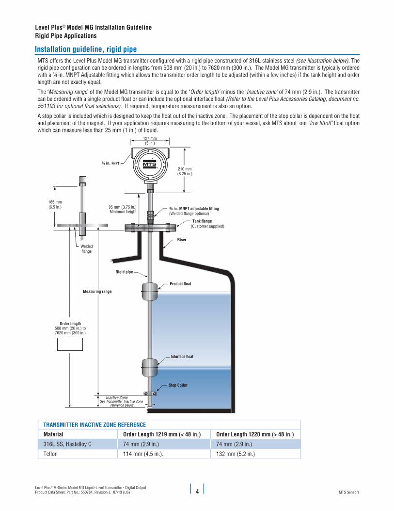
Installation guideline, rigid pipeMTS offers the Level Plus Model MG transmitter configured with a rigid pipe constructed of 316L stainless steel (see illustration below). The rigid pipe configuration can be ordered in lengths from 508 mm (20 in.) to 7620 mm (300 in.). The Model MG transmitter is typically ordered with a ¾ in. MNPT Adjustable fitting which allows the transmitter order length to be adjusted (within a few inches) if the tank height and order length are not exactly equal.
The ‘Measuring range’ of the Model MG transmitter is equal to the ‘Order length’ minus the ‘Inactive zone’ of 74 mm (2.9 in.). The transmitter can be ordered with a single product float or can include the optional interface float (Refer to the Level Plus Accessories Catalog, document no. 551103 for optional float selections). If required, temperature measurement is also an option.
A stop collar is included which is designed to keep the float out of the inactive zone. The placement of the stop collar is dependent on the float and placement of the magnet. If your application requires measuring to the bottom of your vessel, ask MTS about our ‘low liftoff’ float option which can measure less than 25 mm (1 in.) of liquid.
165 mm(6.5 in.)
Weldedflange
See Transmitter Inactive Zone reference below
FNPT
TRANSMITTER INACTIVE ZONE REFERENCE
Material Order Length 1219 mm (< 48 in.) Order Length 1220 mm (> 48 in.)
316L SS, Hastelloy C 74 mm (2.9 in.) 74 mm (2.9 in.)
Teflon 114 mm (4.5 in.). 132 mm (5.2 in.)
Level Plus® Model MG Installation GuidelineRigid Pipe Applications
Level Plus® M-Series Model MG Liquid-Level Transmitter - Digital OutputProduct Data Sheet, Part No.: 550784, Revision J, 07/13 (US)MTS Sensors 5
Level Plus® Model MG Installation GuidelineFlexible Hose Applications
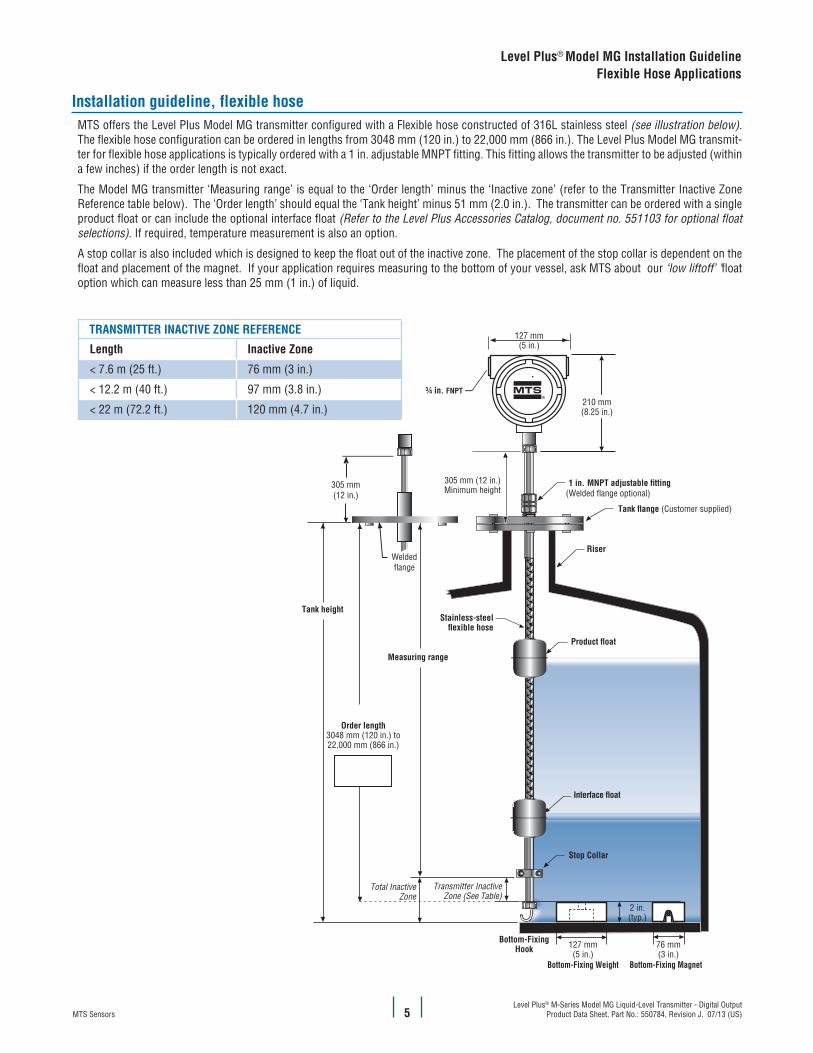
Installation guideline, flexible hoseMTS offers the Level Plus Model MG transmitter configured with a Flexible hose constructed of 316L stainless steel (see illustration below). The flexible hose configuration can be ordered in lengths from 3048 mm (120 in.) to 22,000 mm (866 in.). The Level Plus Model MG transmit-ter for flexible hose applications is typically ordered with a 1 in. adjustable MNPT fitting. This fitting allows the transmitter to be adjusted (within a few inches) if the order length is not exact.
The Model MG transmitter ‘Measuring range’ is equal to the ‘Order length’ minus the ‘Inactive zone’ (refer to the Transmitter Inactive Zone Reference table below). The ‘Order length’ should equal the ‘Tank height’ minus 51 mm (2.0 in.). The transmitter can be ordered with a single product float or can include the optional interface float (Refer to the Level Plus Accessories Catalog, document no. 551103 for optional float selections). If required, temperature measurement is also an option.
A stop collar is also included which is designed to keep the float out of the inactive zone. The placement of the stop collar is dependent on the float and placement of the magnet. If your application requires measuring to the bottom of your vessel, ask MTS about our ‘low liftoff’ ’float option which can measure less than 25 mm (1 in.) of liquid.
TRANSMITTER INACTIVE ZONE REFERENCE
Length Inactive Zone
< 7.6 m (25 ft.) 76 mm (3 in.)
< 12.2 m (40 ft.) 97 mm (3.8 in.)
< 22 m (72.2 ft.) 120 mm (4.7 in.)
(Customer supplied)
Stainless-steel
Riser
127 mm(5 in.)
210 mm(8.25 in.)
Stop Collar
305 mm (12 in.)Minimum height
Total InactiveZone
Transmitter InactiveZone (See Table)
76 mm(3 in.)
2 in.(typ.)
127 mm(5 in.)
Bottom-FixingHook
Bottom-Fixing Weight Bottom-Fixing Magnet
Tank height
Order length3048 mm (120 in.) to22,000 mm (866 in.)
Measuring range
305 mm(12 in.)
Weldedflange
FNPT
Level Plus® M-Series Model MG Liquid-Level Transmitter - Digital OutputProduct Data Sheet, Part No.: 550784, Revision J, 07/13 (US) MTS Sensors6
Level Plus® Model MG Installation GuidelineSanitary Pipe Applications
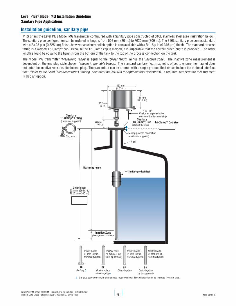
Installation guideline, sanitary pipeMTS offers the Level Plus Model MG transmitter configured with a Sanitary pipe constructed of 316L stainless steel (see illustration below). The sanitary pipe configuration can be ordered in lengths from 508 mm (20 in.) to 7620 mm (300 in.). The 316L sanitary pipe comes standard with a Ra 25 μ in (0.625 μm) finish, however an electropolish option is also available with a Ra 15 μ in (0.375 μm) finish. The standard process fitting is a welded Tri-Clamp® cap. Because the Tri-Clamp cap is welded, it is imperative that the correct order length is provided. The order length should be equal to the height from the bottom of the tank to the top of the process connection on the tank.
The Model MG transmitter ‘Measuring range’ is equal to the ‘Order length’ minus the ‘Inactive zone’. The inactive zone measurement is dependent on the end plug style chosen (shown in the table below). The standard sanitary float magnet is offset to ensure the magnet does not enter the inactive zone despite the end plug. The transmitter can be ordered with a single product float or can include the optional interface float (Refer to the Level Plus Accessories Catalog, document no. 551103 for optional float selections). If required, temperature measurement is also an option.
Tri-Clamp® Cap sizeSanitary
Tri-Clamp® Cap
SanitaryTri-Clamp® Fitting
Inactive Zone(See important note below)
½ in. FNPT
Inactive zone81 mm (3.2 in.)from tip (typical)
Inactive zone74 mm (2.9 in.)from tip (typical)
Inactive zone81 mm (3.2 in.)from tip (typical)
Inactive zone74 mm (2.9 in.)from tip (typical)
TBSanitary ◊
DPDrain-in-place
with end plug ◊
CPClean-in-place
DNDrain-in-place
no through hole
◊ End plug style comes with permanently mounted floats. These floats cannot be removed from the pipe.
Level Plus® M-Series Model MG Liquid-Level Transmitter - Digital OutputProduct Data Sheet, Part No.: 550784, Revision J, 07/13 (US)MTS Sensors 7
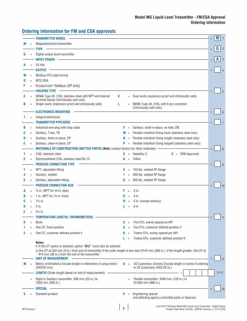
Ordering information for FM and CSA approvalsTRANSMITTER MODEL = M 1
M = Magnetostrictive transmitter
TYPE = G 2
G = Digital output level transmitter
INPUT POWER = A 3
A = 24 Vdc
OUTPUT = 4
M = Modbus RTU data format
D = MTS DDAF = FOUNDATION™ fieldbus (XP only)
HOUSING TYPE = 5
3 = NEMA Type 4X, 316L stainless steel with NPT and internal terminal blocks (Intrinsically safe only)
C = Dual cavity (explosion-proof and intrinsically safe)
B = Single cavity (explosion-proof and intrinsically safe) L = NEMA Type 4X, 316L with 6-pin connector (Intrinsically safe only)
ELECTRONICS MOUNTING = 6
1 = Integral electronics
TRANSMITTER PIPE/HOSE = 7
B = Industrial end-plug with stop collar F = Sanitary, drain-in-place, no hole, DN
C = Sanitary, T-bar, TB M = Flexible w/bottom fixing hook (stainless steel only)
D = Sanitary, drain-in-place, DP N = Flexible w/bottom fixing weight (stainless steel only)
E = Sanitary, clean-in-place, CP P = Flexible w/bottom fixing magnet (stainless steel only)
MATERIALS OF CONSTRUCTION (WETTED PARTS) (Note: contact factory for other materials) = 8
1 = 316L stainless steel 3 = Hastelloy C C = CRN Approved2 = Electropolished 316L stainless steel Ra 15 A = Teflon
PROCESS CONNECTION TYPE = 9
1 = NPT, adjustable fitting 6 = 150 lbs. welded RF flange4 = Sanitary, welded 7 = 300 lbs. welded RF flange
5 = Sanitary, adjustable fitting 8 = 600 lbs. welded RF flange
PROCESS CONNECTION SIZE = 10
A = ¾ in. (NPT for 5∕8 in. pipe) F = 3 in.
B = 1 in. (NPT for 7∕8 in. hose) G = 4 in.C = 1½ in. H = 5 in. (except sanitary)
D = 2 in. J = 6 in.
E = 2½ in.
TEMPERATURE (DIGITAL THERMOMETERS) = 11
0 = None 5 = Five DTs, evenly spaced as API1 = One DT, fixed position 6 = Five DTs, customer defined position łł
2 = One DT, customer defined position łł K = Twelve DTs, evenly spaced per API
L = Twelve DTs, customer defined position łłNotes:łł If this DT option is selected, option ‘18 E ’ must also be selected. § One DT at 203 mm (8 in.) from end of transmitter if the order length is less than 9144 mm (360 in.). If the length greater, One DT at 914 mm (36 in.) from the end of the transmitter.UNIT OF MEASUREMENT = 12
M = Metric (millimeters) Encode length in millimeters if using metric (XXXXX mm)
U = US Customary (inches) Encode length in inches if ordering in US Customary (XXX.XX in.)
LENGTH (Order length based on unit of measurement) = 13-17
= Rigid or Sanitary transmitter: 508 mm (20 in.) to 7620 mm (300 in.)
= Flexible transmitter: 3048 mm (120 in.) to 22,000 mm (866 in.)
SPECIAL = 18
S = Standard product E = Engineering special (not affecting agency controlled parts or features)
Model MG Liquid-Level Transmitter - FM/CSA Approval Ordering information
Level Plus® M-Series Model MG Liquid-Level Transmitter - Digital OutputProduct Data Sheet, Part No.: 550784, Revision J, 07/13 (US) MTS Sensors8
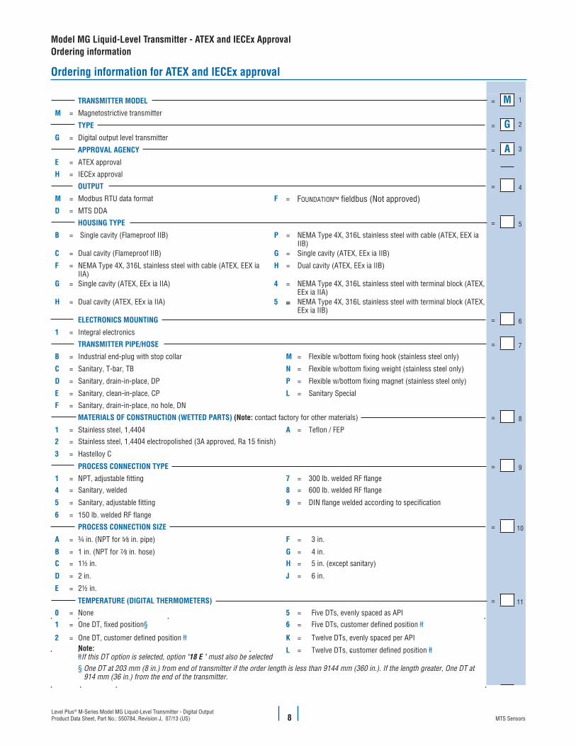
Ordering information for ATEX and IECEx approval
TRANSMITTER MODEL = M 1
M = Magnetostrictive transmitter
TYPE = G 2
G = Digital output level transmitter
APPROVAL AGENCY = A 3
E = ATEX approval
H = IECEx approval
OUTPUT = 4
M = Modbus RTU data format F = FOUNDATION™ fieldbus (Not approved)D = MTS DDA
HOUSING TYPE = 5
B = Single cavity (Flameproof IIB) P = NEMA Type 4X, 316L stainless steel with cable (ATEX, EEX ia IIB)
C = Dual cavity (Flameproof IIB) G = Single cavity (ATEX, EEx ia IIB)
F = NEMA Type 4X, 316L stainless steel with cable (ATEX, EEX ia IIA)
H = Dual cavity (ATEX, EEx ia IIB)
G = Single cavity (ATEX, EEx ia IIA) 4 = NEMA Type 4X, 316L stainless steel with terminal block (ATEX, EEx ia IIA)
H = Dual cavity (ATEX, EEx ia IIA) 5 = NEMA Type 4X, 316L stainless steel with terminal block (ATEX, EEx ia IIB)
ELECTRONICS MOUNTING = 6
1 = Integral electronics
TRANSMITTER PIPE/HOSE = 7
B = Industrial end-plug with stop collar M = Flexible w/bottom fixing hook (stainless steel only)
C = Sanitary, T-bar, TB N = Flexible w/bottom fixing weight (stainless steel only)
D = Sanitary, drain-in-place, DP P = Flexible w/bottom fixing magnet (stainless steel only)
E = Sanitary, clean-in-place, CP L = Sanitary Special
F = Sanitary, drain-in-place, no hole, DN
MATERIALS OF CONSTRUCTION (WETTED PARTS) (Note: contact factory for other materials) = 8
1 = Stainless steel, 1,4404 A = Teflon / FEP2 = Stainless steel, 1,4404 electropolished (3A approved, Ra 15 finish)
3 = Hastelloy C
PROCESS CONNECTION TYPE = 9
1 = NPT, adjustable fitting 7 = 300 lb. welded RF flange4 = Sanitary, welded 8 = 600 lb. welded RF flange
5 = Sanitary, adjustable fitting 9 = DIN flange welded according to specification
6 = 150 lb. welded RF flange
PROCESS CONNECTION SIZE = 10
A = ¾ in. (NPT for 5∕8 in. pipe) F = 3 in.
B = 1 in. (NPT for 7∕8 in. hose) G = 4 in. C = 1½ in. H = 5 in. (except sanitary)
D = 2 in. J = 6 in.
E = 2½ in.
TEMPERATURE (DIGITAL THERMOMETERS) = 11
0 = None 5 = Five DTs, evenly spaced as API1 = One DT, fixed position§ 6 = Five DTs, customer defined position łł
2 = One DT, customer defined position łł K = Twelve DTs, evenly spaced per APINote:łłIf this DT option is selected, option ‘18 E ’ must also be selected
L = Twelve DTs, customer defined position łł
§ One DT at 203 mm (8 in.) from end of transmitter if the order length is less than 9144 mm (360 in.). If the length greater, One DT at 914 mm (36 in.) from the end of the transmitter.
Model MG Liquid-Level Transmitter - ATEX and IECEx ApprovalOrdering information

Level Plus® M-Series Model MG Liquid-Level Transmitter - Digital OutputProduct Data Sheet, Part No.: 550784, Revision J, 07/13 (US)MTS Sensors 9
UNIT OF MEASUREMENT = 12
M = Metric (millimeters) Encode length in millimeters if using metric (XXXXX mm)
U = US Customary (inches) Encode length in inches if ordering in US Customary (XXX.XX in.)
LENGTH (Order length based on unit of measurement) = 13-17
= Rigid or Sanitary transmitter: 508 mm (20 in.) to 7620 mm (300 in.)
= Flexible transmitter: 3048 mm (120 in.) to 22,000 mm (866 in.) except ATEX Ex ia IIB max. length 13500 mm (531 in.)
= Teflon: 508 mm (20 in.) to 6096 mm (240 in.)
SPECIAL = 18
S = Standard product E = Engineering special (not affecting agency controlled parts or features)
Model MG Liquid-Level Transmitter - ATEX ApprovalOrdering information
Ordering information continued
Level Plus® M-Series Model MG Liquid-Level Transmitter - Digital OutputProduct Data Sheet, Part No.: 550784, Revision J, 07/13 (US)MTS Sensors
Level Plus® Model MG AccessoriesStandard Product Floats
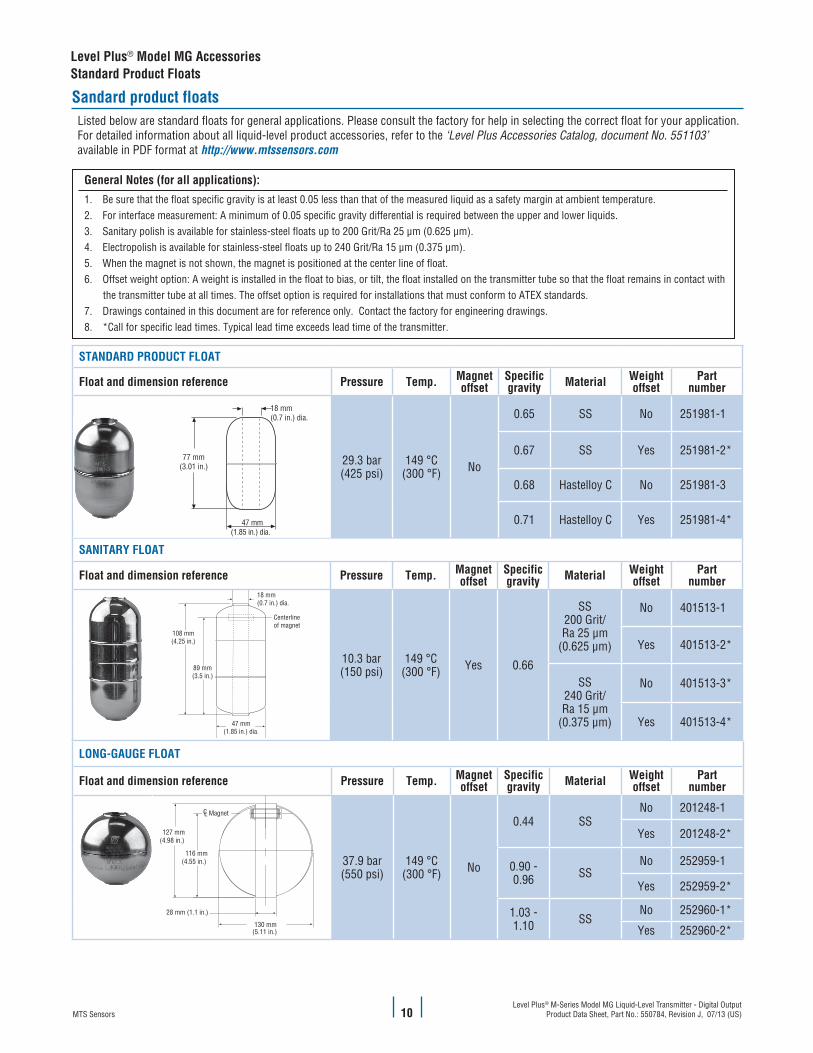
Sandard product floatsListed below are standard floats for general applications. Please consult the factory for help in selecting the correct float for your application. For detailed information about all liquid-level product accessories, refer to the ‘Level Plus Accessories Catalog, document No. 551103’ available in PDF format at http://www.mtssensors.com
General Notes (for all applications):
1. Be sure that the float specific gravity is at least 0.05 less than that of the measured liquid as a safety margin at ambient temperature. 2. For interface measurement: A minimum of 0.05 specific gravity differential is required between the upper and lower liquids. 3. Sanitary polish is available for stainless-steel floats up to 200 Grit/Ra 25 μm (0.625 μm).4. Electropolish is available for stainless-steel floats up to 240 Grit/Ra 15 μm (0.375 μm).5. When the magnet is not shown, the magnet is positioned at the center line of float. 6. Offset weight option: A weight is installed in the float to bias, or tilt, the float installed on the transmitter tube so that the float remains in contact with the transmitter tube at all times. The offset option is required for installations that must conform to ATEX standards.7. Drawings contained in this document are for reference only. Contact the factory for engineering drawings.8. *Call for specific lead times. Typical lead time exceeds lead time of the transmitter.
STANDARD PRODUCT FLOAT
Float and dimension reference Pressure Temp. Magnetoffset
Specificgravity Material Weight
offsetPart
number
18 mm(0.7 in.) dia.
47 mm(1.85 in.) dia.
77 mm(3.01 in.) 29.3 bar
(425 psi)149 °C
(300 °F) No
0.65 SS No 251981-1
0.67 SS Yes 251981-2*
0.68 Hastelloy C No 251981-3
0.71 Hastelloy C Yes 251981-4*
SANITARY FLOAT
Float and dimension reference Pressure Temp. Magnetoffset
Specificgravity Material Weight
offsetPart
number18 mm(0.7 in.) dia.
47 mm(1.85 in.) dia.
Centerline of magnet
89 mm(3.5 in.)
108 mm(4.25 in.)
10.3 bar(150 psi)
149 °C(300 °F) Yes 0.66
SS200 Grit/Ra 25 μm
(0.625 μm)
No 401513-1
Yes 401513-2*
SS240 Grit/Ra 15 μm
(0.375 μm)
No 401513-3*
Yes 401513-4*
LONG-GAUGE FLOAT
Float and dimension reference Pressure Temp. Magnetoffset
Specificgravity Material Weight
offsetPart
number
130 mm(5.11 in.)
127 mm(4.98 in.)
116 mm(4.55 in.)
28 mm (1.1 in.)
CL Magnet
37.9 bar(550 psi)
149 °C(300 °F) No
0.44 SSNo 201248-1
Yes 201248-2*
0.90 - 0.96 SS
No 252959-1
Yes 252959-2*
1.03 -1.10 SS
No 252960-1*
Yes 252960-2*
10
MTS Systems CorporationSensors Division
3001 Sheldon DriveCary, North Carolina27513, USATel.: +1-800-633-7609Fax: +1-919-677-2343 +1-800-498-4442e-mail: [email protected]://www.mtssensors.com
MTS Sensor TechnologieGmbH & Co. KG
Auf dem Schüffel 9D - 58513 Lüdenscheid, GermanyTel.: +49-2351-9587-0Fax: +49-2351-56491e-mail: [email protected]://www.mtssensor.de
MTS Sensors TechnologyCorporation
737 Aihara-cho, Machida-shiTokyo 194-0211, JapanTel.: +81-42-775-3838Fax: +81-42-775-5516e-mail: [email protected]://www.mtssensor.co.jp
SENSORS
®
MTS, Temposonics and Level Plus are registered trademarks of MTS Systems Corporation. All other trademarks are the property of their respective owners. Printed in USA. Copyright © 2013 MTS Systems Corporation. All Rights Reserved in all media.
All specifications are subject to change. Contact MTS for specifications and engineering drawings that are critical to your application. Drawings contained in this document are for reference only. Go to http://www.mtssensors.com for the latest support documentation and related media.
Document Part Number: 550784 Revision J, 07/13 (US)
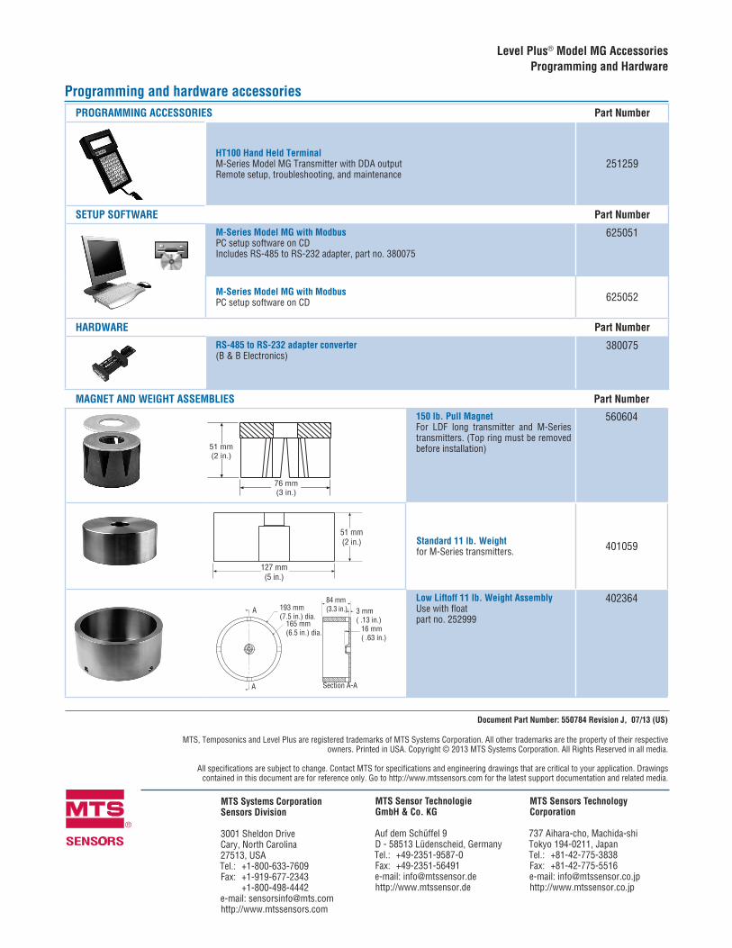
Programming and hardware accessoriesPROGRAMMING ACCESSORIES Part Number
HT100 Hand Held TerminalM-Series Model MG Transmitter with DDA outputRemote setup, troubleshooting, and maintenance
251259
SETUP SOFTWARE Part Number
M-Series Model MG with ModbusPC setup software on CDIncludes RS-485 to RS-232 adapter, part no. 380075
625051
M-Series Model MG with ModbusPC setup software on CD 625052
HARDWARE Part Number
RS-485 to RS-232 adapter converter(B & B Electronics)
380075
MAGNET AND WEIGHT ASSEMBLIES Part Number
51 mm(2 in.)
76 mm(3 in.)
150 lb. Pull MagnetFor LDF long transmitter and M-Series transmitters. (Top ring must be removed before installation)
560604
51 mm(2 in.)
127 mm(5 in.)
Standard 11 lb. Weightfor M-Series transmitters. 401059
A
A
193 mm(7.5 in.) dia.
165 mm(6.5 in.) dia.
Section A-A
84 mm(3.3 in.) 3 mm
( .13 in.)16 mm( .63 in.)
Low Liftoff 11 lb. Weight Assembly Use with float part no. 252999
402364
Level Plus® Model MG AccessoriesProgramming and Hardware