level transmitter
DESCRIPTION
transmitterTRANSCRIPT
MODULE 4: Level Instrumentation
MODULE OBJECTIVES:
At the end of this module, you will be able to:1. Sketch and explain the principle of an open tank level
measurement installation using a level transmitter.
2. Sketch and explain the principle of a closed tank level measurement installation using a level transmitter and dry leg.
3. Explain the purpose of a three-valve manifold in closed tank level measurement installations.
4. State the procedure required for valving a level transmitter:a) into service, andb) out of servicewhen a three valve manifold is used.
5. Briefly explain the principle of operation of a closed tank, wet leg, level measurement installation.
6. Briefly explain the need fora) zero suppression, andb) zero elevationin level measurement installations by reference to an example process application for each case.
7. Briefly explain the principle of operation of a bubbler level measurement system.
8. List two advantages of a bubbler system.
Inferential Level Measurement Inferential level measurement techniques obtain a level indication
indirectly by monitoring the pressure exerted by the column of liquid.
The pressure at the base of a vessel containing liquid is directly proportional to the liquid level in the vessel. As the level in the vessel rises, the pressure exerted by the liquid at the base of the vessel will increase linearly.
Mathematically, we have the pressure and level dependency of:P = S xHwhereP = Pressure (Pa)S = Weight density of the liquid (N/m3)H = Height of liquid column (m)
The level of liquid inside a tank can be determined from the pressure reading at the base of the tank, if the specific gravity of the liquid is constant.
Differential pressure transmitters are the most commonly used instrumentation devices to measure the pressure at the base of a tank.
When a DP transmitter is used for the purpose of measuring level, it will be called a level transmitter even though it is measuring pressure.
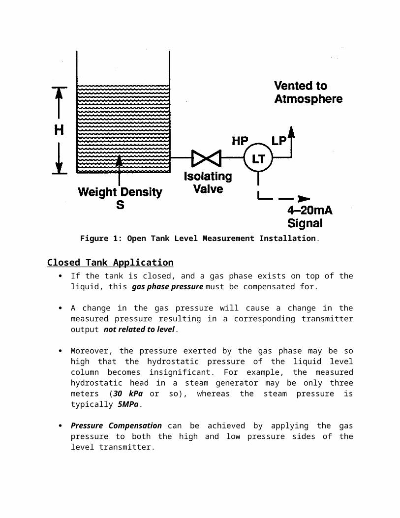
Open Tank Level Measurement ApplicationThe simplest level transmitter application is the measurement of level in an open tank. Figure 1 shows a typical open tank level measurement installation.
If the tank is open to atmosphere, the high pressure side of the D/P level transmitter will be connected to the base of the tank.
The low pressure side will be vented to atmosphere.
In this manner, the level transmitter acts as a simple pressure transmitter. We have:
Phigh = Patm + S xHPlow = Patm
Differential pressure DP = Phigh - Plow = S xH
The level transmitter can be calibrated to output 4 mA when the tank is at 0% level and 20 mA when the tank is at 100% level.
Figure 1: Open Tank Level Measurement Installation.
Closed Tank Application If the tank is closed, and a gas phase exists on top of the liquid, this
gas phase pressure must be compensated for.
A change in the gas pressure will cause a change in the measured pressure resulting in a corresponding transmitter output not related to level.
Moreover, the pressure exerted by the gas phase may be so high that the hydrostatic pressure of the liquid level column becomes insignificant. For example, the measured hydrostatic head in a steam generator may be only three meters (30 kPa or so), whereas the steam pressure is typically 5MPa.
Pressure Compensation can be achieved by applying the gas pressure to both the high and low pressure sides of the level transmitter.
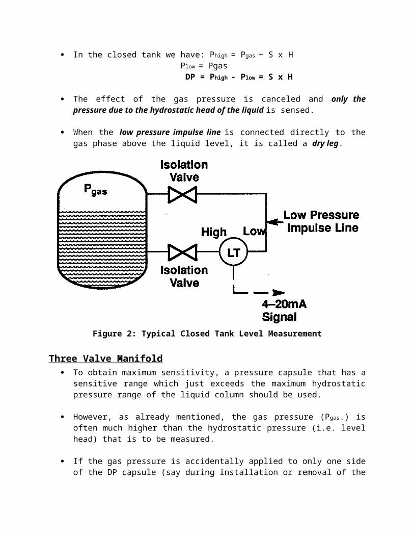
In the closed tank we have: Phigh = Pgas + S xH Plow = Pgas DP = Phigh - Plow = S x H
The effect of the gas pressure is canceled and only the pressure due to the hydrostatic head of the liquid is sensed.
When the low pressure impulse line is connected directly to the gas phase above the liquid level, it is called a dry leg.
Figure 2: Typical Closed Tank Level Measurement
Three Valve Manifold To obtain maximum sensitivity, a pressure capsule that has a sensitive
range which just exceeds the maximum hydrostatic pressure range of the liquid column should be used.
However, as already mentioned, the gas pressure (Pgas.) is often much higher than the hydrostatic pressure (i.e. level head) that is to be measured.
If the gas pressure is accidentally applied to only one side of the DP capsule (say during installation or removal of the DP transmitter), over ranging of the capsule could occur and the capsule would be damaged.
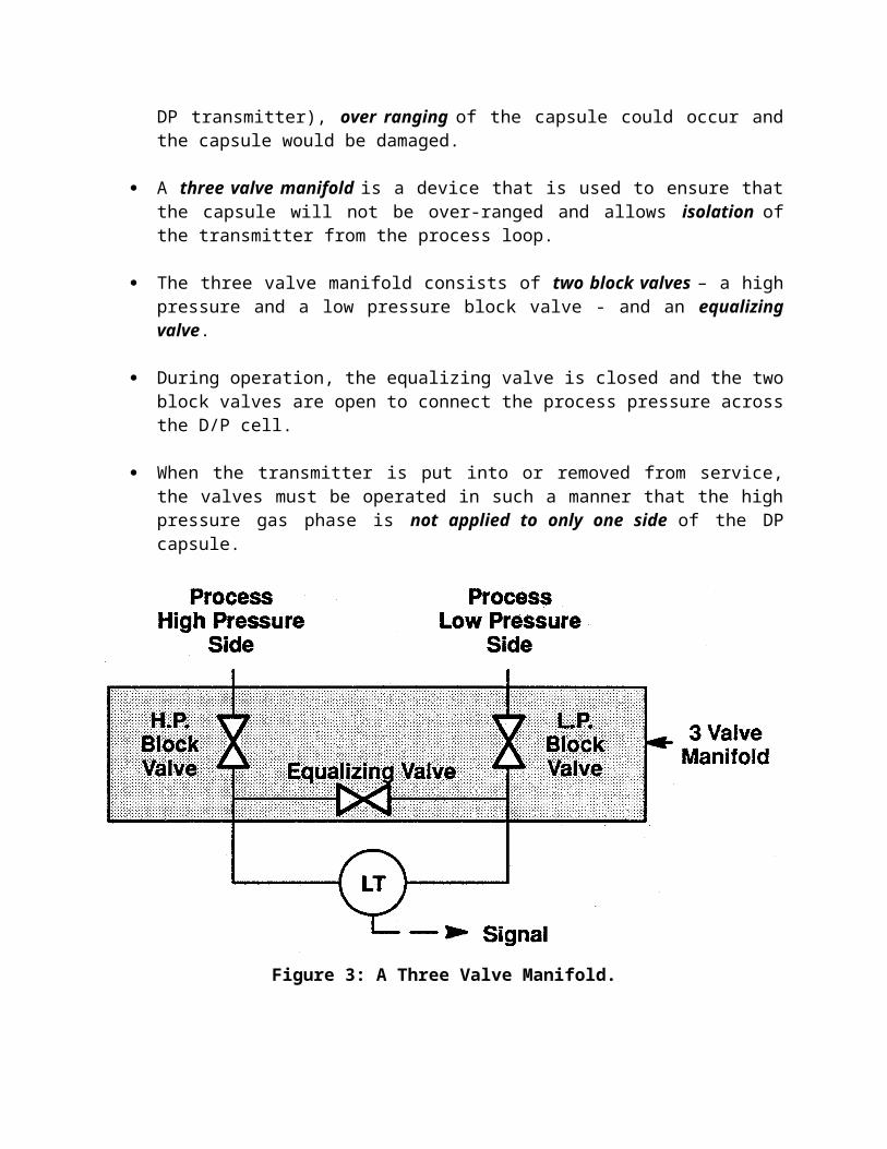
A three valve manifold is a device that is used to ensure that the capsule will not be over-ranged and allows isolation of the transmitter from the process loop.
The three valve manifold consists of two block valves – a high pressure and a low pressure block valve - and an equalizing valve.
During operation, the equalizing valve is closed and the two block valves are open to connect the process pressure across the D/P cell.
When the transmitter is put into or removed from service, the valves must be operated in such a manner that the high pressure gas phase is not applied to only one side of the DP capsule.
Figure 3: A Three Valve Manifold.
Operational Sequences of Three-Valve ManifoldValving a d/P Transmitter Into ServiceTo valve the DP transmitter into service, the following steps should be followed:
1. Check all valves closed.
2. Open the equalizing valve - this ensures that the same pressure will be applied to both sides of the transmitter, i.e. zero differential pressure.
3. Open the High Pressure block valve slowly, check for leakage from both the high pressure and low pressure side of the transmitter – still zero d/P.
4. Close the equalizing valve - this locks the pressure on both sides of the transmitter – now look for leaks, should still be zero d/P.
5. Open the low pressure block valve to apply the process pressure to the low pressure side of the transmitter and establish the working differential pressure.
6. The transmitter is now in service.
Note it may be necessary to purge any trapped air from the capsule housing as this can lead to level indication errors and create attendant control problems.Operational Sequences of Three-Valve Manifold- Valving a Transmitter-out-of-ServiceReversal of the previous steps allows the d/P transmitter to be removed from service. The starting operating state is with the equalizing valve closed andboth block valves open.
1. Close the low pressure block valve to trap pressure in the low side – check for leaks and ensure the indicated d/P does not change.
2. Open the equalizing valve to force d/P to zero.
3. Close the high pressure block valve to isolate the transmitter.
4. Bleed down (i.e. vent) the pressure trapped in the d/P cell body – should continue to read zero d/P
5. The d/P transmitter is now out-of-service, isolated and depressurized.
Dry Leg SystemA full dry leg installation with three valve manifold is shown in Figure 4.
If the gas phase is condensable, such as steam, condensate will form in the low pressure impulse line resulting in a column of liquid which exerts extra pressure on the low pressure side of the transmitter (i.e. transmitter will read in error low).
A technique to solve this problem is to add a condensate or knock-out pot below the transmitter in the low pressure side as shown in Figure 4. Periodic draining of the condensate in the knock-out pot will ensure that the impulse line is free of liquid so that the dry leg is in fact dry.
A disadvantage of the dry leg that restricts its use is the frequent maintenance that may be required. One example of a dry leg application is the measurement of liquid level in a closed tank with a purge cover gas pressure.
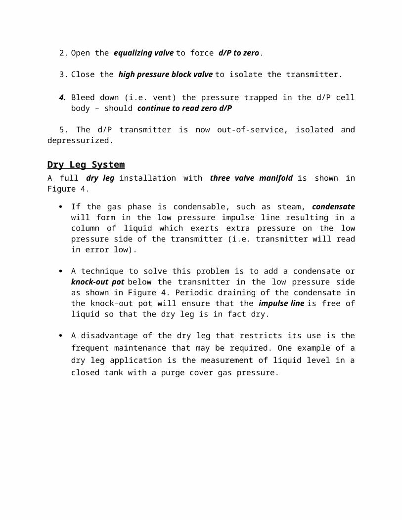
Figure 4: Dry Leg Installation with a Three Valve Manifold.
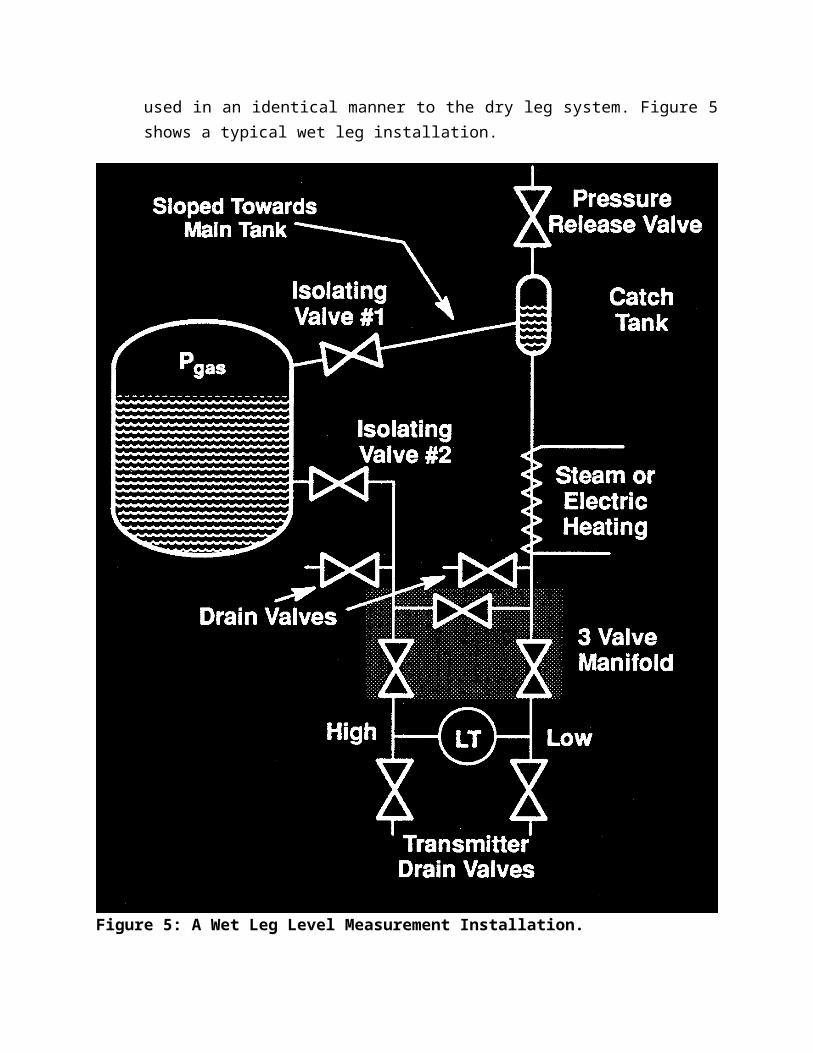
Wet Leg System In a wet leg system, the low pressure impulse line is completely
filled with liquid (usually the same liquid as the process), and hence the name "wet leg". A d/P level transmitter, with an associated three valve manifold, is used in an identical manner to the dry leg system. Figure 5 shows a typical wet leg installation.
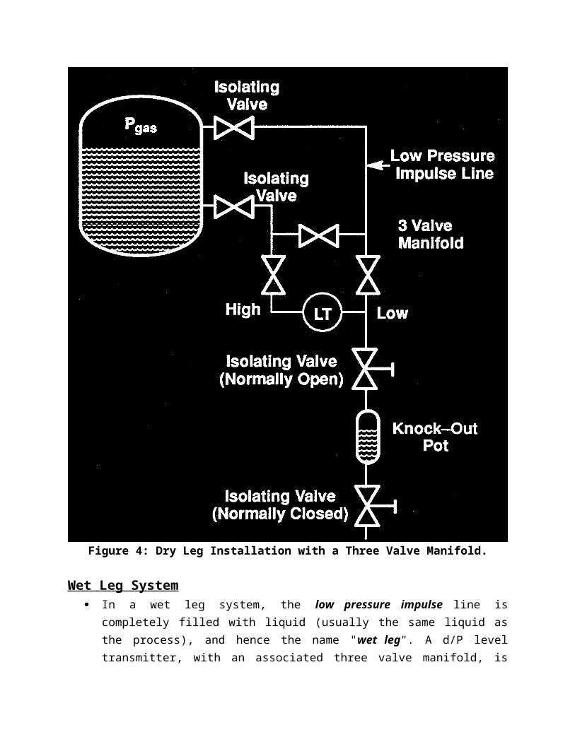
Figure 5: A Wet Leg Level Measurement Installation.
Wet Leg Installation Overview At the top of the low pressure impulse line is a small constant head
catch tank.
The vapour from the gas phase will condense in the wet leg and the catch tank.
The catch tank, with the sloped interconnecting line back to the tank, maintains a constant hydrostatic pressure on the low pressure side of the level transmitter.
This pressure error, being a constant low signal component, can easily be corrected for by calibration.
If the tank is located outdoors, trace heating of the wet leg might be necessary to prevent it from freezing. Steam lines or an electric heating element can be wound around the wet leg to keep the temperature of the condensate above its freezing point.
Note the two sets of drain valves. The transmitter drain valves would be used to drain (bleed) the transmitter only. The two drain valves located immediately above the three valve manifold are used for impulse and wet leg draining or filling.
To isolate the wet leg transmitter installation for maintenance:(a) Isolate the d/P transmitter using the standard three valve isolating
procedure (described earlier in this module).
(b) Close the HP and LP isolating valves (isolate process). This gives two point isolation.
(c) Open pressure relief valve (bleed system pressure from wet leg). Reclose pressure relief valve and re-open after five minutes. If there is a further release of pressure the upper isolation valve is passing. If no further leakage then leave valve open.
(d) Bleed system pressure from d/P cell using the transmitter drain valves.
Zero SuppressionIn some cases, it is impossible to mount the level transmitter right at the base level of the tank. Say for maintenance access purposes, the level transmitter must be mounted X meters below the base of an open tank as shown in Figure 6.
The liquid in the tank exerts a varying pressure, proportional to its level (H), on the high pressure side of the transmitter
The liquid in the high pressure impulse line also exerts a pressure on the high pressure side. However, this pressure is a constant (P = S X) and is present at all times.
When the liquid level is at H meters, pressure on the high pressure side of the transmitter will be:
Phigh = S H + S X + Patm
Plow = Patm
DP = Phigh - Plow = S H + S X
Figure 6: Level Transmitter with Zero Suppression.
That is, the pressure on the high pressure side of the d/P cell is always higher than the actual pressure exerted by the liquid column in the tank by (S X) – so the reading will be in error high.
This constant pressure would cause an output signal that is higher than 4 mA when the tank is empty and above 20 mA when it is full (if the transmitter is calibrated 4-20mA for the S H range.)
The transmitter has to be negatively biased by a value of S .X so that the output of the transmitter is proportional to the tank level (S H) only.
This procedure is called Zero Suppression and is done during calibration of the transmitter.
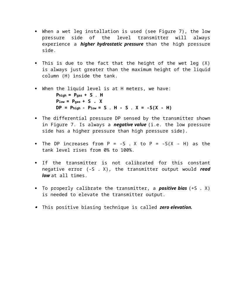
Zero Elevation When a wet leg installation is used (see Figure 7), the low pressure
side of the level transmitter will always experience a higher hydrostatic pressure than the high pressure side.
This is due to the fact that the height of the wet leg (X) is always just greater than the maximum height of the liquid column (H) inside the tank.
When the liquid level is at H meters, we have:Phigh = Pgas + S HPlow = Pgas + S .XDP = Phigh - Plow = S H - S X = -S(X - H)
The differential pressure DP sensed by the transmitter shown in Figure 7. Is always a negative value (i.e. the low pressure side has a higher pressure than high pressure side).
The DP increases from P = -S X to P = -S(X - H) as the tank level rises from 0% to 100%.
If the transmitter is not calibrated for this constant negative error (-S X), the transmitter output would read low at all times.
To properly calibrate the transmitter, a positive bias (+S X) is needed to elevate the transmitter output.
This positive biasing technique is called zero elevation.
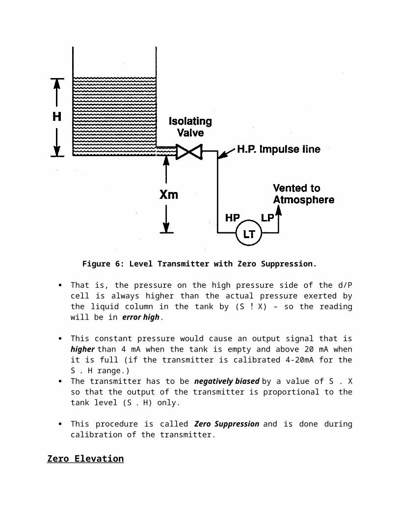
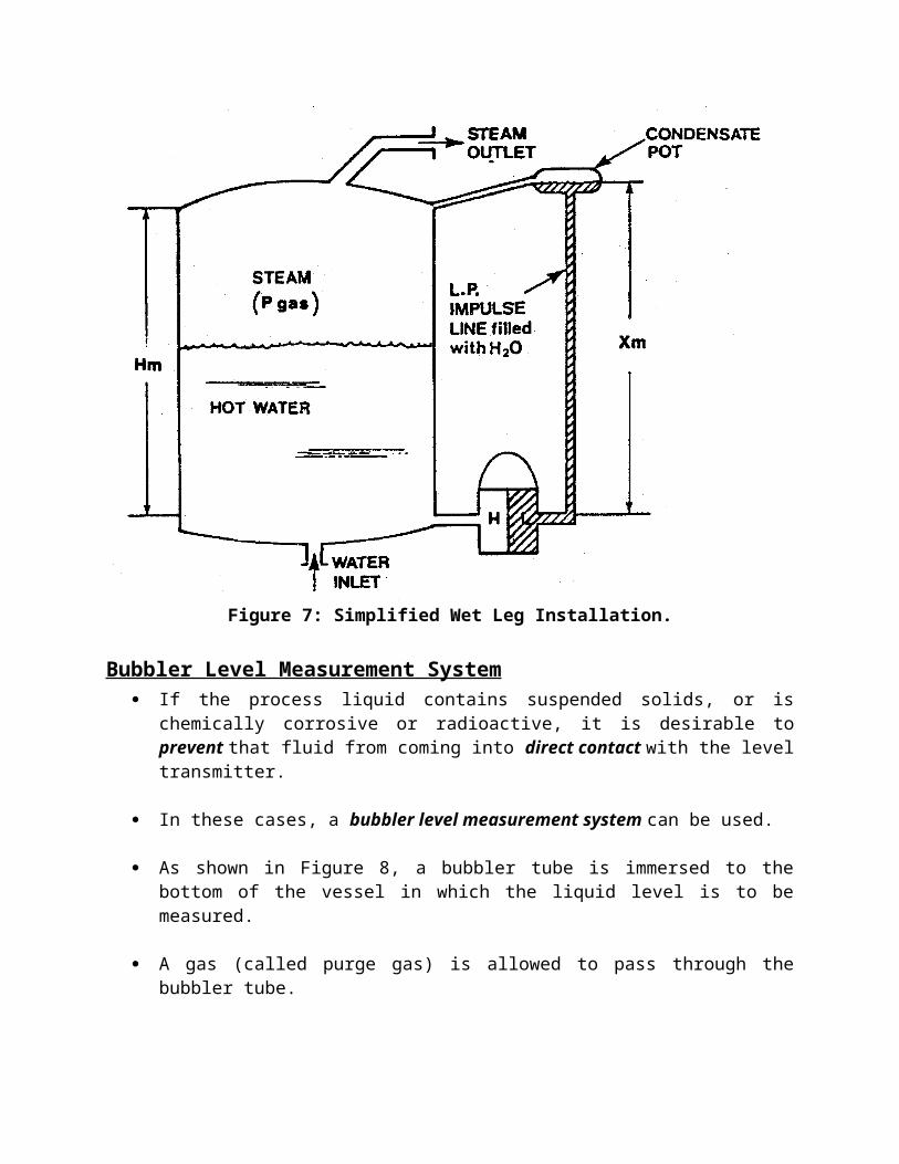
Figure 7: Simplified Wet Leg Installation.
Bubbler Level Measurement System If the process liquid contains suspended solids, or is chemically
corrosive or radioactive, it is desirable to prevent that fluid from coming into direct contact with the level transmitter.
In these cases, a bubbler level measurement system can be used.
As shown in Figure 8, a bubbler tube is immersed to the bottom of the vessel in which the liquid level is to be measured.
A gas (called purge gas) is allowed to pass through the bubbler tube.
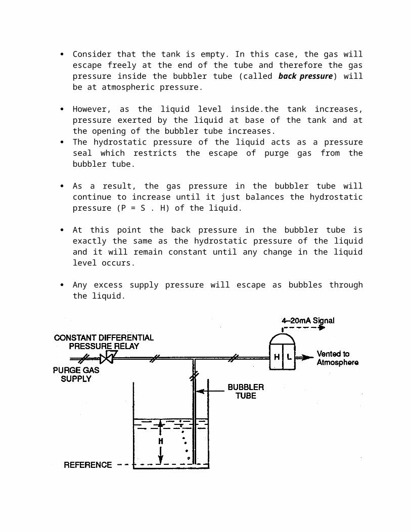
Consider that the tank is empty. In this case, the gas will escape freely at the end of the tube and therefore the gas pressure inside the bubbler tube (called back pressure) will be at atmospheric pressure.
However, as the liquid level inside.the tank increases, pressure exerted by the liquid at base of the tank and at the opening of the bubbler tube increases.
The hydrostatic pressure of the liquid acts as a pressure seal which restricts the escape of purge gas from the bubbler tube.
As a result, the gas pressure in the bubbler tube will continue to increase until it just balances the hydrostatic pressure (P = S .H) of the liquid.
At this point the back pressure in the bubbler tube is exactly the same as the hydrostatic pressure of the liquid and it will remain constant until any change in the liquid level occurs.
Any excess supply pressure will escape as bubbles through the liquid.
Figure 8: Bubbler Level Measurement System In Open Tank Application.
Open-Tank Bubbler Level Measurement System Description As the liquid level rises, the back-pressure in the bubbler tube
increases proportionally, since the density of the liquid is constant.
A level transmitter can be used to monitor this back-pressure.
In an open tank installation, the bubbler tube pressure is connected to the high pressure side of the transmitter, while the low pressure side is vented to atmosphere. The output of the transmitter will be proportional to the tank level.
A constant differential pressure relay is often used in the purge gas supply line to ensure that bubbling action occurs at all tank levels.
The constant differential pressure relay maintains a constant flow rate of purge gas in the bubbler tube regardless of tank level variations or supply fluctuation.
This ensures that bubbling will occur for the maximum tank level and the flow rate does not increase at low tank levels in such a way as to cause excessive disturbances at the surface of liquid.
Note that bubbling action has to be continuous, or the measurement signal will not be accurate.
An additional advantage of the bubbler system is that since it measures only the back-pressure of the purge gas, the exact location of the level transmitter is not important. The transmitter can be mounted some distance from the process.
Closed Tank Application For Bubbler System If the bubbler system is to be applied to measure level in a closed tank,
some pressure regulating scheme must be provided for the gas space in the tank.
Otherwise, the gas bubbling through the liquid will pressurize the gas space to a point where bubbler supply pressure cannot overcome the static pressure.
The result would be no bubbler purge flow and, therefore, an inaccurate measurement signal.
Also, as in the case of a closed tank inferential level measurement system, the low pressure side of the level transmitter has to be connected to the gas space in order to compensate for the effect of gas pressure.
In this way, the bubbler medium (say helium) back-pressures are applied against both the high side and low sides of the d/P cell to provide a differential pressure signal proportional to the level in the closed tank.
Module 4: Review Questions
1. State the relationship between pressure at the base of the tank and liquid column height.
2. Sketch a level transmitter installation for a closed tank application. Show all necessary pipe connections.
3. Sketch and explain the function of a three valve manifold.
4. Describe an operating sequence for the three valve manifold when a d/P transmitter has to be placed into service. Assume that the static pressure could over-range the capsule if incorrectly applied.
5. What is the difference between a "dry" leg and a "wet" leg in closed tank application?
6. In a wet leg installation, the low pressure side of the DP transmitter always experiences a higher pressure than the high pressure side. What would be the effect of reversing the connections such that the wet leg is connected to the high pressure side of the transmitter.
7. When a wet leg installation is used, the "zero" has to be elevated. Explain the reason for this zero elevation.
8. Briefly explain the principle of operation of a bubbler system.
9. List the two main advantages of the bubbler system in a nuclear system.