lg-25-pm lg-25-sm(fm1311) 12-13 - fimco industriesfm1… · - correct part description and/or part...
TRANSCRIPT
Warranty/Parts/ServiceFor home usage, products are warranted for one year from date of purchase against manufacturer or workmanship defects.
Commercial users have a 90 day warranty.
Your authorized dealer is the best source of replacement parts and service. To obtain prompt, efficient service, always remember to give the following information...
- Correct Part Description and/or part number. - Model number/Serial number of your sprayer.
Part descriptions and part numbers can be obtained from the illustrated parts list section(s) of this manual.
Whenever you need parts or repair service, contact your distributor/dealer first. For warranty work, always take your original sales slip, or other evidence of purchase date, to your distributor/dealer.
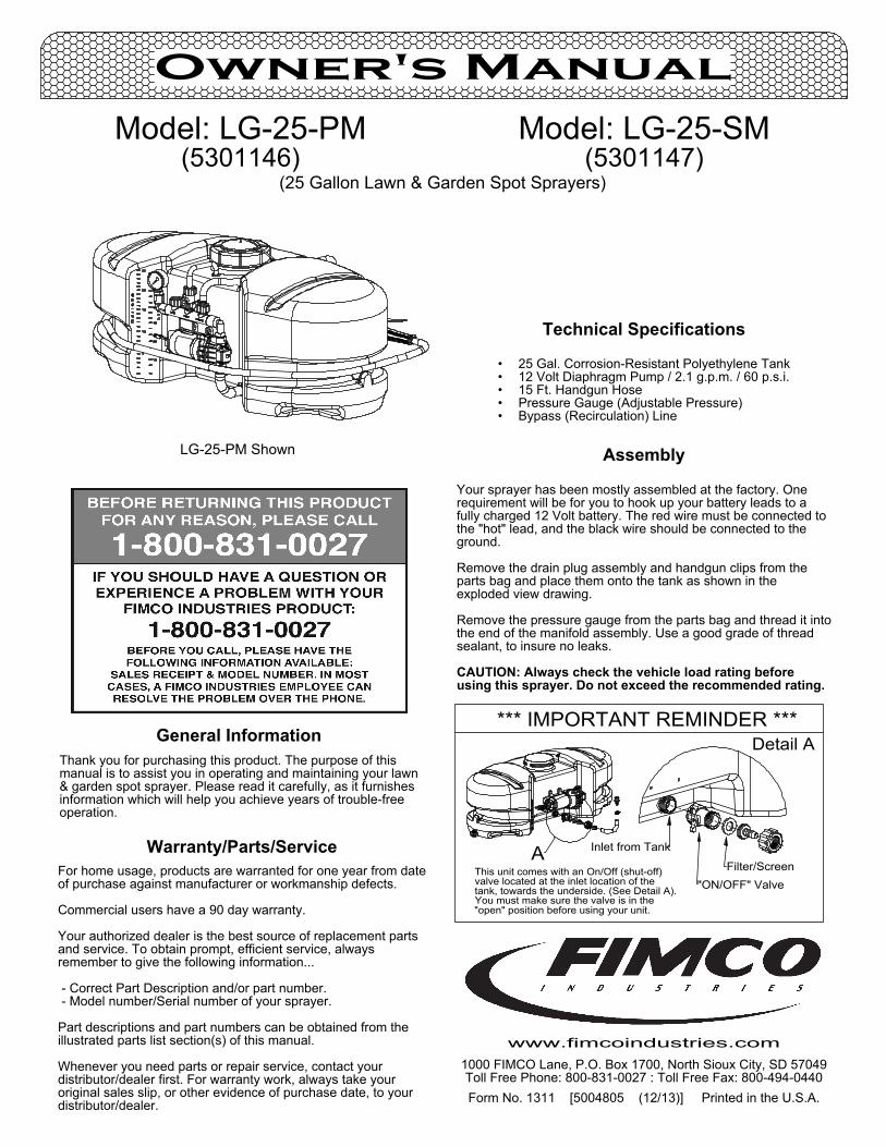
"ON/OFF" Valve
*** IMPORTANT REMINDER ***
A Inlet from Tank
Filter/Screen
Detail A
"open" position before using your unit.You must make sure the valve is in thetank, towards the underside. (See Detail A).valve located at the inlet location of theThis unit comes with an On/Off (shut-off)
25 Gal. Corrosion-Resistant Polyethylene Tank•12 Volt Diaphragm Pump / 2.1 g.p.m. / 60 p.s.i.•15 Ft. Handgun Hose•Pressure Gauge (Adjustable Pressure)•Bypass (Recirculation) Line•
Technical Specifications
Form No. 1311 [5004805 (12/13)] Printed in the U.S.A.
Model: LG-25-PM (5301146)
(25 Gallon Lawn & Garden Spot Sprayers)
Owner's Manual
Model: LG-25-SM(5301147)
General InformationThank you for purchasing this product. The purpose of this manual is to assist you in operating and maintaining your lawn & garden spot sprayer. Please read it carefully, as it furnishes information which will help you achieve years of trouble-free operation.
1000 FIMCO Lane, P.O. Box 1700, North Sioux City, SD 57049Toll Free Phone: 800-831-0027 : Toll Free Fax: 800-494-0440
www.fimcoindustries.com
Assembly
Your sprayer has been mostly assembled at the factory. One requirement will be for you to hook up your battery leads to a fully charged 12 Volt battery. The red wire must be connected to the "hot" lead, and the black wire should be connected to the ground.
Remove the drain plug assembly and handgun clips from the parts bag and place them onto the tank as shown in the exploded view drawing.
Remove the pressure gauge from the parts bag and thread it into the end of the manifold assembly. Use a good grade of thread sealant, to insure no leaks.
CAUTION: Always check the vehicle load rating before using this sprayer. Do not exceed the recommended rating.
LG-25-PM Shown
527xxxx 0101000000
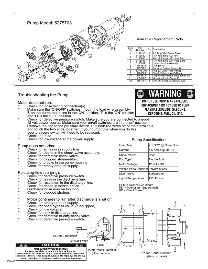
Pump Model: 5275703
Inle
tO
utle
t
Available Replacement Parts
and touch the two ends together. If your pump runs when you do this,Remove the cap to the pressure switch. Pull both red wires off of their terminals,12 volt power source. Make sure your on/off switches are in the 'on' position.Check for defective pressure switch. Make sure you are connected to a good
& on the pump motor are in the 'ON' position. "I" is the 'ON' positionMake sure the 'ON/OFF' switches in both the lead wire assembly
Pump 'Model' Number
Motor continues to run after discharge is shut off:
° Check the fuse.
Check for defective pressure switch.Check for defective or dirty check valve.Check for leak in discharge line.Check for low voltage.Check for open bypass valve. (if equipped)Check for empty product supply.
Check for clogged strainer.Discharge hose may be too long.Check for debris in nozzle orifice.Check for restriction in the discharge line.Check for leaks in the discharge line.Check for defective pressure switch.
Pulsating flow (surging):
Check for empty product supply.Check for cracks in the pump housing.Check for clogged strainer/filter.Check for defective check valve.Check for debris in the check valve assembly.Check for air leaks in supply line.
Pump does not prime:
Check for low voltage at the power supply.
°
°
°°
°
°°
°°
°
°°
°°
°
°°°
°°
°
On/Off Switch
12 Volt Connection
Fuse
and 'O' is the 'OFF' position.
Check for loose wiring connection(s).Motor does not run:
Troubleshooting the Pump:
your pressure switch will need to be replaced.
3
°
°°
76
52
89
4
10
5
Pump 'Serial' Number
4.5 Amps @ 30 PSI
2.1 GPM @ Open Flow
3.19
DC = Direct CurrentPSI = Pounds per Square InchGPM = Gallons Per Minute
Liquid Temperature:
Wetted Parts Housing:
Motor Voltage:
Pump Specifications
2.25
Diaphragm:
Port Type:Check Valve:
Current:
Flow Rate:
130 F max.°
Santoprene
Polypropylene
12 Volts DC
Plug-In PortViton
On/Off Rocker Switch w/CoverMounting Feet (Pkg of 4)Diaphragm/Piston/Cam/Bearing KitCheck Valve Kit (w/O-Ring)Pkg. (2) Clips (Port Fitting)Pressure Switch Assembly
Upper Housing AssemblyPort Kit Fitting, 3/8" Hose BarbPort Kit Fitting, 1/2" Hose BarbPort Kit Fitting, 1/2" MNPT7.5 Amp 'Mini Blade' Fuse
11 DescriptionQtyNumberNo
5157207509520251688385168820
20408-0005157202516883951688375168836516883351688325157205
8
1211109
4
765
321
Plunger Kit
1
1
11
1
1
11
1
11
1
Item Part
12
(Here on Label)(Here on Label)
Page 2

ON/OFF Switch Information For Your Sprayer
"o" is OFF
(12 Volt Pump)
"-" is ON
in the ON (-) positionThis switch is shown"ON" position before operating your sprayer.
Make sure BOTH of these switches are in thenumber system, where 1=ON and 0=OFF)(These symbols are based off the binary"o" is for the OFF position"-" is for the ON positionThings you need to know about the switches:your battery connecting cable. (in most cases)plastic cover. A similar switch will be located on'rear' of the pump, located underneath a clearswitches. The one on the pump will be at theYour sprayer may be equipped with (2) ON/OFF
1711
4
3
5
5
6
14
20
16
9
192221
12
10
13
23
15
18
2
1
8
7
Page 3
Exploded View/Parts List:LG-25-PM (5301146) & LG-25-SM (5301147)
Item No
Part Number LG-25-PM/Qty LG-25-SM/Qty Description
1 5006209 1 1 Poly Knurled Swivel Nut, 3/4" FGHT2 5016066 1 1 Garden Hose Washer3 5020524 1 1 Hose, 3/8"-1 Brd. x 15 Ft.4 5051122 1 1 5/8" Black Nylon Loom Cable Clamp5 5051144 2 2 Hose Clamp, 3/8"6 5058188 1 1 Tank Lid w/Lanyard7 5075018 1 1 Grommet8 5100359 1 1 Poly Bypass "J" Hose (3.8/2.1 - 25 Gal.)9 5100452 1 1 Siphon Tube
10 5117167 3 3 #10-24 x 5/8" Phillips Truss Head Machine Screw11 5117234 1 1 #10-24 x 1/2" Phillips Truss Head Machine Screw12 5117313 1 1 #10-24 x 2 1/2" Truss Head Machine Screw13 5127191 1 1 Manifold Spacer (2.1gpm)14 5163100 1 - Low-Flow Handgun w/X-26 Tip15 5167007 1 1 Pressure Gauge, 0-100 p.s.i.16 5169243 1 1 25 Gallon Tank (White/Side-Mount Pump)17 5273959 - 1 Deluxe Pistol-Grip Handgun w/X-26 Tip18 5274373 1 1 Drain Plug Cap, Tether, and Washer Assembly19 5274443 1 1 Lead Wire Assembly (w/Switch), 96"20 5274880 1 1 Handgun Clips & Screws (Pkg/2) (#10-24 Thread)21 5275703 1 1 Gold Series 2.1 g.p.m. Pump (60 psi, 8 Amp)22 5275877 1 1 Intake Sub-Assembly23 5277686 1 1 Manifold Assembly (Spot Sprayers)
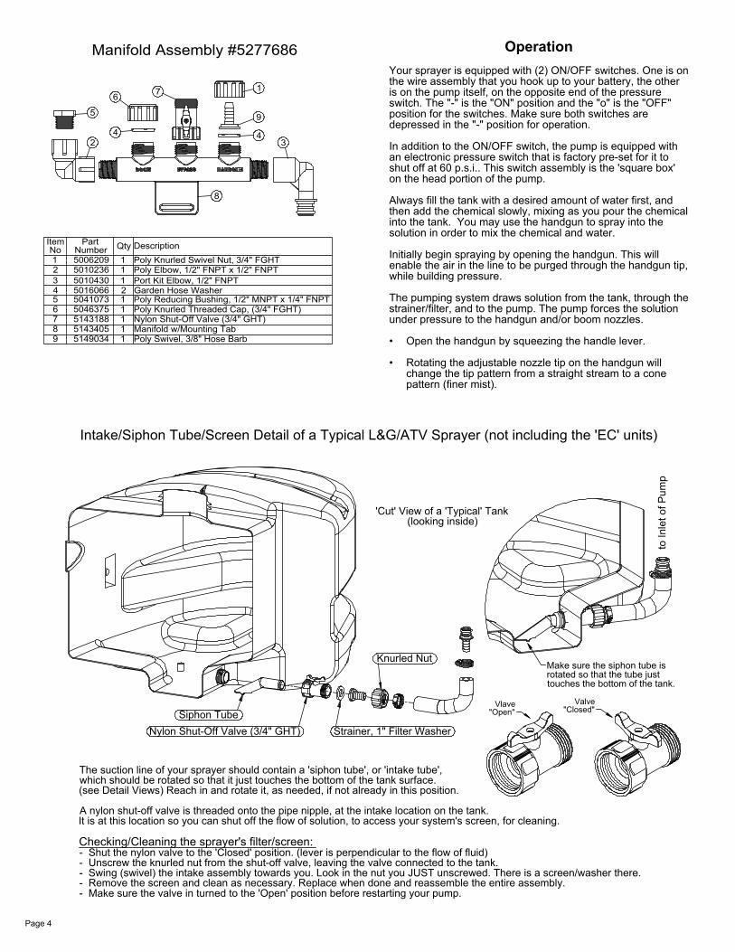
Intake/Siphon Tube/Screen Detail of a Typical L&G/ATV Sprayer (not including the 'EC' units)
to In
let o
f Pum
p
Strainer, 1" Filter Washer
- Make sure the valve in turned to the 'Open' position before restarting your pump.- Remove the screen and clean as necessary. Replace when done and reassemble the entire assembly.- Swing (swivel) the intake assembly towards you. Look in the nut you JUST unscrewed. There is a screen/washer there.- Unscrew the knurled nut from the shut-off valve, leaving the valve connected to the tank.- Shut the nylon valve to the 'Closed' position. (lever is perpendicular to the flow of fluid)
It is at this location so you can shut off the flow of solution, to access your system's screen, for cleaning.A nylon shut-off valve is threaded onto the pipe nipple, at the intake location on the tank.
(see Detail Views) Reach in and rotate it, as needed, if not already in this position.which should be rotated so that it just touches the bottom of the tank surface.The suction line of your sprayer should contain a 'siphon tube', or 'intake tube',
Checking/Cleaning the sprayer's filter/screen:
Nylon Shut-Off Valve (3/4" GHT)Siphon Tube "Closed"
Valve
touches the bottom of the tank.rotated so that the tube justMake sure the siphon tube is
Knurled Nut
"Open"Vlave
(looking inside)'Cut' View of a 'Typical' Tank
Manifold Assembly #5277686
Poly Swivel, 3/8" Hose BarbManifold w/Mounting TabNylon Shut-Off Valve (3/4" GHT)Poly Knurled Threaded Cap, (3/4" FGHT)Poly Reducing Bushing, 1/2" MNPT x 1/4" FNPTGarden Hose WasherPort Kit Elbow, 1/2" FNPTPoly Elbow, 1/2" FNPT x 1/2" FNPTPoly Knurled Swivel Nut, 3/4" FGHTDescription
15143405851490349 1
5143188504637550410735016066501043050102365006209NumberNo
4
67
5
23
1
Item
2
111
111
Part Qty
2
5
4
6
8
7
34
9
1
Page 4
Your sprayer is equipped with (2) ON/OFF switches. One is on the wire assembly that you hook up to your battery, the other is on the pump itself, on the opposite end of the pressure switch. The "-" is the "ON" position and the "o" is the "OFF" position for the switches. Make sure both switches are depressed in the "-" position for operation.
In addition to the ON/OFF switch, the pump is equipped with an electronic pressure switch that is factory pre-set for it to shut off at 60 p.s.i.. This switch assembly is the 'square box' on the head portion of the pump.
Always fill the tank with a desired amount of water first, and then add the chemical slowly, mixing as you pour the chemical into the tank. You may use the handgun to spray into the solution in order to mix the chemical and water.
Initially begin spraying by opening the handgun. This will enable the air in the line to be purged through the handgun tip, while building pressure.
The pumping system draws solution from the tank, through the strainer/filter, and to the pump. The pump forces the solution under pressure to the handgun and/or boom nozzles.
Open the handgun by squeezing the handle lever.•
Rotating the adjustable nozzle tip on the handgun will •change the tip pattern from a straight stream to a cone pattern (finer mist).
Operation
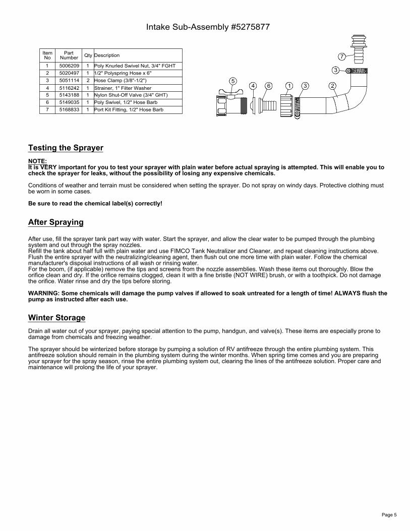
Intake Sub-Assembly #5275877
5168833514903551431885116242505111450204975006209
Number
76
NoItem
345
12
Part
Port Kit Fitting, 1/2" Hose BarbPoly Swivel, 1/2" Hose Barb
11
Nylon Shut-Off Valve (3/4" GHT)Strainer, 1" Filter WasherHose Clamp (3/8"-1/2")1/2" Polyspring Hose x 6"Poly Knurled Swivel Nut, 3/4" FGHT
DescriptionQty
211
11
265
4 1 3
7
3
After Spraying
After use, fill the sprayer tank part way with water. Start the sprayer, and allow the clear water to be pumped through the plumbing system and out through the spray nozzles.Refill the tank about half full with plain water and use FIMCO Tank Neutralizer and Cleaner, and repeat cleaning instructions above.Flush the entire sprayer with the neutralizing/cleaning agent, then flush out one more time with plain water. Follow the chemical manufacturer's disposal instructions of all wash or rinsing water.For the boom, (if applicable) remove the tips and screens from the nozzle assemblies. Wash these items out thoroughly. Blow the orifice clean and dry. If the orifice remains clogged, clean it with a fine bristle (NOT WIRE) brush, or with a toothpick. Do not damage the orifice. Water rinse and dry the tips before storing.
WARNING: Some chemicals will damage the pump valves if allowed to soak untreated for a length of time! ALWAYS flush the pump as instructed after each use.
NOTE:It is VERY important for you to test your sprayer with plain water before actual spraying is attempted. This will enable you to check the sprayer for leaks, without the possibility of losing any expensive chemicals.
Conditions of weather and terrain must be considered when setting the sprayer. Do not spray on windy days. Protective clothing must be worn in some cases.
Be sure to read the chemical label(s) correctly!
Testing the Sprayer
Winter StorageDrain all water out of your sprayer, paying special attention to the pump, handgun, and valve(s). These items are especially prone to damage from chemicals and freezing weather.
The sprayer should be winterized before storage by pumping a solution of RV antifreeze through the entire plumbing system. This antifreeze solution should remain in the plumbing system during the winter months. When spring time comes and you are preparing your sprayer for the spray season, rinse the entire plumbing system out, clearing the lines of the antifreeze solution. Proper care and maintenance will prolong the life of your sprayer.
Page 5