lg lwd3081st 30” electric convection built-in oven sm
TRANSCRIPT

1
30” ELECTRIC CONVECTIONBUILT-IN OVENSERVICE MANUALMODEL: LWD3081ST
CAUTIONBEFORE SERVICING THE UNIT, READ THE SAFETY PRECAUTIONS IN THIS MANUAL.
P/NO : MFL37118304June, 2008
Printed in Korea
삼 흥정 판
Internal Use Only
Website http://biz.lgservice.com

This LG Service Manual, “30” Electric Built-in Oven”, provides the technician with information onthe operation and service of the Electric Built-in Oven. It is to be used as a training ServiceManual. For specific information on the model being serviced, refer to the “Owner’s Manual” or“Tech Sheet” provided with the electric oven.
SAFETY PRECAUTIONS• Repairs of the appliance should be carried out by a licensed technician only. Incorrect repairs
may result in dangerous situations. If you need repairs, contact an LG Service Center or yourdealer.
• If the power cord is defective, it must be replaced by a qualified service agent with a UL listedrange cord.
• Electrical leads and cables should not be allowed to touch the oven.
• Rating plate is located on the bracket below the control panel.
• The power supply of the appliance should be turned off when it is being repaired.
FORWARD
LG Electronics assumes no responsibility for any repairs madeon our products by anyone other than Authorized Service Technicians.
WARNING• DISCONNECT power supply cord from the outlet before servicing.• Replace all panels and parts before operating.• RECONNECT all grounding devices.- Failure to do so can result in severe personal injury, death or electrical shock.• DO NOT Touch when the oven operates.- The interior parts will be very hot.

(PAGE)
GENERAL- - - - - - - - - - - - - - - - - - - - - - - - - - - - - - - - - - - - - - - - - - - - - - - - - - - - - - - - - - - - - - - - - - - - - - - - - - - - - - - - - - - - - - - - - - - - 1-1 ~ 1-6• Read all instructions before use - - - - - - - - - - - - - - - - - - - - - - - - - - - - - - - - - - - - - - - - - - - - - - - - - - - - - - - - - - - - - - - - - - - - - - - - - - - - - - - - - 1-1 ~ 1-4• Model & Serial number label and tech sheet locations - - - - - - - - - - - - - - - - - - - - - - - - - - - - - - - - - - - - - - - - - - - - - - - - - - - - - - - - - - - 1-5• Specifications - - - - - - - - - - - - - - - - - - - - - - - - - - - - - - - - - - - - - - - - - - - - - - - - - - - - - - - - - - - - - - - - - - - - - - - - - - - - - - - - - - - - - - - - - - - - - - - - - - - - - - - - - - - - - - - - - - 1-6
USING YOUR RANGE - - - - - - - - - - - - - - - - - - - - - - - - - - - - - - - - - - - - - - - - - - - - - - - - - - - - - - - - - - - - - - - - - - - - - - - - - 2-1 ~ 2-5• General information - - - - - - - - - - - - - - - - - - - - - - - - - - - - - - - - - - - - - - - - - - - - - - - - - - - - - - - - - - - - - - - - - - - - - - - - - - - - - - - - - - - - - - - - - - - - - - - - - - - - - - - - - 2-1• Control panel feature - - - - - - - - - - - - - - - - - - - - - - - - - - - - - - - - - - - - - - - - - - - - - - - - - - - - - - - - - - - - - - - - - - - - - - - - - - - - - - - - - - - - - - - - - - - - - - - - 2-2 ~ 2-5
- Setting the initial control- Start, clean/off- Oven light (Upper/Lower)- Timer- Control lockout- Set up: 8 different category
1) Language selection2) Temperature selection unit3) Display brightness4) Sound volume Loud/Normal/Mute5) Convection auto conversion6) Temperature adjustment7) Clock time8) Reset
- Bake- Timed cook, Delayed timed cook- Broil- Roast- Convection bake- Crisp convection- Convection roast- Recipe bank- Proof/Warm- Healthier roast- My menu- Option- Self clean
DISASSEMBLY INSTRUCTIONS - - - - - - - - - - - - - - - - - - - - - - - - - - - - - - - - - - - - - - - - - - - - - - - - - - - - - - - - - - 3-1 ~ 3-3• Component Locations- - - - - - - - - - - - - - - - - - - - - - - - - - - - - - - - - - - - - - - - - - - - - - - - - - - - - - - - - - - - - - - - - - - - - - - - - - - - - - - - - - - - - - - - 3-1
DISASSEMBLY INSTRUCTIONS(UPPER) - - - - - - - - - - - - - - - - - - - - - - - - - - - - - - - - - - - - - - - - - - - - - 3-2 ~ 3-3• Replacing the control panel and related components - - - - - - - - - - - - - - - - - - - - - - - - - - - - - - - - - - - - - - - - - - - - - - - - - - - - - - - - - 3-2~3-3
- Removing the Low Voltage Transformer (controller)- - - - - - - - - - - - - - - - - - - - - - - - - - - - - - - - - - - - - - - - - - - - - - - - - - - - - - - - - - - - - - 3-2- Removing the Relay PCB - - - - - - - - - - - - - - - - - - - - - - - - - - - - - - - - - - - - - - - - - - - - - - - - - - - - - - - - - - - - - - - - - - - - - - - - - - - - - - - - - - - - - - - - - - - - - - - - - 3-3- Removing the door lock assembly- - - - - - - - - - - - - - - - - - - - - - - - - - - - - - - - - - - - - - - - - - - - - - - - - - - - - - - - - - - - - - - - - - - - - - - - - - - - - - - - - - - - - - 3-3- Removing the Low Voltage Transformer (halogen lamp) - - - - - - - - - - - - - - - - - - - - - - - - - - - - - - - - - - - - - - - - - - - - - - - - - - - - - - - - 3-3- Removing the Serge filter - - - - - - - - - - - - - - - - - - - - - - - - - - - - - - - - - - - - - - - - - - - - - - - - - - - - - - - - - - - - - - - - - - - - - - - - - - - - - - - - - - - - - - - - - - - - - - - - - 3-3
DISASSEMBLY INSTRUCTIONS(UPPER/LOWER) - - - - - - - - - - - - - - - - - - - - - - - - - - - - - - - - - 3-4 ~ 3-5• Replacing oven cavity components - - - - - - - - - - - - - - - - - - - - - - - - - - - - - - - - - - - - - - - - - - - - - - - - - - - - - - - - - - - - - - - - - - - - - - - - - - - - - - - 3-4 ~ 3-5
- Removing the Broil element - - - - - - - - - - - - - - - - - - - - - - - - - - - - - - - - - - - - - - - - - - - - - - - - - - - - - - - - - - - - - - - - - - - - - - - - - - - - - - - - - - - - - - - - - - - - - - 3-4- Removing the Convection element - - - - - - - - - - - - - - - - - - - - - - - - - - - - - - - - - - - - - - - - - - - - - - - - - - - - - - - - - - - - - - - - - - - - - - - - - - - - - - - - - - - - - 3-4- Removing the Blade fan - - - - - - - - - - - - - - - - - - - - - - - - - - - - - - - - - - - - - - - - - - - - - - - - - - - - - - - - - - - - - - - - - - - - - - - - - - - - - - - - - - - - - - - - - - - - - - - - - - - 3-5- Removing the Halogen lamp & socket assembly - - - - - - - - - - - - - - - - - - - - - - - - - - - - - - - - - - - - - - - - - - - - - - - - - - - - - - - - - - - - - - - - - - 3-5
• Replacing other electrical components. - - - - - - - - - - - - - - - - - - - - - - - - - - - - - - - - - - - - - - - - - - - - - - - - - - - - - - - - - - - - - - - - - - - - - - - - - - 3-6 ~ 3-9
TABLE OF CONTENTS
- Removing the Vent motor - - - - - - - - - - - - - - - - - - - - - - - - - - - - - - - - - - - - - - - - - - - - - - - - - - - - - - - - - - - - - - - - - - - - - - - - - - - - - - - - - - - - - - - - - - - - - - - - - 3-6- Removing the Thermal limiter - - - - - - - - - - - - - - - - - - - - - - - - - - - - - - - - - - - - - - - - - - - - - - - - - - - - - - - - - - - - - - - - - - - - - - - - - - - - - - - - - - - - - - - - - - - 3-7- Removing the Door switch - - - - - - - - - - - - - - - - - - - - - - - - - - - - - - - - - - - - - - - - - - - - - - - - - - - - - - - - - - - - - - - - - - - - - - - - - - - - - - - - - - - - - - - - - - - - - - - 3-7- Removing the Thermal limiter (Double Line Brake_Upper) - - - - - - - - - - - - - - - - - - - - - - - - - - - - - - - - - - - - - - - - - - - - - - - - - - - - - 3-8- Removing the Convection motor assembly - - - - - - - - - - - - - - - - - - - - - - - - - - - - - - - - - - - - - - - - - - - - - - - - - - - - - - - - - - - - - - - - - - - - - - - - - 3-8- Removing the Hidden bake element - - - - - - - - - - - - - - - - - - - - - - - - - - - - - - - - - - - - - - - - - - - - - - - - - - - - - - - - - - - - - - - - - - - - - - - - - - - 3-8 ~ 3-9
DISASSEMBLY INSTRUCTIONS(LOWER) - - - - - - - - - - - - - - - - - - - - - - - - - - - - - - - - - - - - - - - - - - 3-10 ~ 3-11 - Removing the Thermal limiter (Double Line Brake_Lower) - - - - - - - - - - - - - - - - - - - - - - - - - - - - - - - - - - - - - - - - - - - - - - - - - - - 3-11- Removing the Convection motor assembly - - - - - - - - - - - - - - - - - - - - - - - - - - - - - - - - - - - - - - - - - - - - - - - - - - - - - - - - - - - - - - - - - - - - - - - - 3-11- Removing the Thermal limiter - - - - - - - - - - - - - - - - - - - - - - - - - - - - - - - - - - - - - - - - - - - - - - - - - - - - - - - - - - - - - - - - - - - - - - - - - - - - - - - - - - - - - - - - - - 3-11- Removing the Hidden bake element - - - - - - - - - - - - - - - - - - - - - - - - - - - - - - - - - - - - - - - - - - - - - - - - - - - - - - - - - - - - - - - - - - - - - - - - - - - - - - - - - 3-11- Removing the vent motor - - - - - - - - - - - - - - - - - - - - - - - - - - - - - - - - - - - - - - - - - - - - - - - - - - - - - - - - - - - - - - - - - - - - - - - - - - - - - - - - - - - - - - - - - - - - - - - - 3-11- Removing the Door lock motor assembly- - - - - - - - - - - - - - - - - - - - - - - - - - - - - - - - - - - - - - - - - - - - - - - - - - - - - - - - - - - - - - - - - - - - - - - - - - - 3-11- Removing the Door switch - - - - - - - - - - - - - - - - - - - - - - - - - - - - - - - - - - - - - - - - - - - - - - - - - - - - - - - - - - - - - - - - - - - - - - - - - - - - - - - - - - - - - - - - - - - - - - 3-11
DISASSEMBLY INSTRUCTIONS(UPPER/LOWER)- - - - - - - - - - - - - - - - - - - - - - - - - - - - - - 3-12 ~ 3-15• Removing & Reinstalling the lift-off oven door - - - - - - - - - - - - - - - - - - - - - - - - - - - - - - - - - - - - - - - - - - - - - - - - - - - - - - - - - - - - - - - - - - - - - - - 3-12• Removing the oven door handle & glass- - - - - - - - - - - - - - - - - - - - - - - - - - - - - - - - - - - - - - - - - - - - - - - - - - - - - - - - - - - - - - - - - - - - - 3-13 ~ 3-14• Removing the oven door gasket- - - - - - - - - - - - - - - - - - - - - - - - - - - - - - - - - - - - - - - - - - - - - - - - - - - - - - - - - - - - - - - - - - - - - - - - - - - - - - - - - - - - - - - - - - 3-15
COMPONENT TEST - - - - - - - - - - - - - - - - - - - - - - - - - - - - - - - - - - - - - - - - - - - - - - - - - - - - - - - - - - - - - - - - - - - - - - - - - - - - - 4-1 ~ 4-4• Convection motor- - - - - - - - - - - - - - - - - - - - - - - - - - - - - - - - - - - - - - - - - - - - - - - - - - - - - - - - - - - - - - - - - - - - - - - - - - - - - - - - - - - - - - - - - - - - - - - - - - - - - - - - - - - - - 4-1• Door locking motor - - - - - - - - - - - - - - - - - - - - - - - - - - - - - - - - - - - - - - - - - - - - - - - - - - - - - - - - - - - - - - - - - - - - - - - - - - - - - - - - - - - - - - - - - - - - - - - - - - - - - - - - - - - 4-2• Door locking micro switch - - - - - - - - - - - - - - - - - - - - - - - - - - - - - - - - - - - - - - - - - - - - - - - - - - - - - - - - - - - - - - - - - - - - - - - - - - - - - - - - - - - - - - - - - - - - - - - - - 4-2• Low Voltage Transformer - Controller - - - - - - - - - - - - - - - - - - - - - - - - - - - - - - - - - - - - - - - - - - - - - - - - - - - - - - - - - - - - - - - - - - - - - - - - - - - - - - - - 4-2• Low Voltage Transformer - Halogen lamp - - - - - - - - - - - - - - - - - - - - - - - - - - - - - - - - - - - - - - - - - - - - - - - - - - - - - - - - - - - - - - - - - - - - - - - - - - 4-2• Oven Thermistor - - - - - - - - - - - - - - - - - - - - - - - - - - - - - - - - - - - - - - - - - - - - - - - - - - - - - - - - - - - - - - - - - - - - - - - - - - - - - - - - - - - - - - - - - - - - - - - - - - - - - - - - - - - - - - 4-3• Door switch - - - - - - - - - - - - - - - - - - - - - - - - - - - - - - - - - - - - - - - - - - - - - - - - - - - - - - - - - - - - - - - - - - - - - - - - - - - - - - - - - - - - - - - - - - - - - - - - - - - - - - - - - - - - - - - - - - - - - 4-3• Oven lamp - - - - - - - - - - - - - - - - - - - - - - - - - - - - - - - - - - - - - - - - - - - - - - - - - - - - - - - - - - - - - - - - - - - - - - - - - - - - - - - - - - - - - - - - - - - - - - - - - - - - - - - - - - - - - - - - - - - - - - 4-3• Broil Element - - - - - - - - - - - - - - - - - - - - - - - - - - - - - - - - - - - - - - - - - - - - - - - - - - - - - - - - - - - - - - - - - - - - - - - - - - - - - - - - - - - - - - - - - - - - - - - - - - - - - - - - - - - - - - - - - - - 4-4• Bake Element - - - - - - - - - - - - - - - - - - - - - - - - - - - - - - - - - - - - - - - - - - - - - - - - - - - - - - - - - - - - - - - - - - - - - - - - - - - - - - - - - - - - - - - - - - - - - - - - - - - - - - - - - - - - - - - - - - 4-4• Convection element - - - - - - - - - - - - - - - - - - - - - - - - - - - - - - - - - - - - - - - - - - - - - - - - - - - - - - - - - - - - - - - - - - - - - - - - - - - - - - - - - - - - - - - - - - - - - - - - - - - - - - - - - 4-4• Vent motor - - - - - - - - - - - - - - - - - - - - - - - - - - - - - - - - - - - - - - - - - - - - - - - - - - - - - - - - - - - - - - - - - - - - - - - - - - - - - - - - - - - - - - - - - - - - - - - - - - - - - - - - - - - - - - - - - - - - - - 4-4
DIAGNOSIS THROUGH SCHEMATIC - - - - - - - - - - - - - - - - - - - - - - - - - - - - - - - - - - - - - - - - - - - - - - - - - - - - - - - - - - - 5-1
HOW TO ENTER THE TEST MODE - - - - - - - - - - - - - - - - - - - - - - - - - - - - - - - - - - - - - - - - - - - - - - - - - - - - - - - - - - - - - - 5-2
SAFETY CAUTION & ERROR CODE SUMMARY - - - - - - - - - - - - - - - - - - - - - - - - - - - - - - - - - - - - - - - - - - - 5-3
CHECKING FLOW CHART BY FAILURE MODE - - - - - - - - - - - - - - - - - - - - - - - - - - - - - - - - - - 5-3 ~ 5-18• Dead - - - - - - - - - - - - - - - - - - - - - - - - - - - - - - - - - - - - - - - - - - - - - - - - - - - - - - - - - - - - - - - - - - - - - - - - - - - - - - - - - - - - - - - - - - - - - - - - - - - - - - - - - - - - - - - - - - - - - - - 5-4 ~ 5-8• Oven does not heat (including F-9, F-19 error) - - - - - - - - - - - - - - - - - - - - - - - - - - - - - - - - - - - - - - - - - - - - - - - - - - - - - - - - - - - - - 5-9 ~ 5-12• Not operating Key (including F-3 error)- - - - - - - - - - - - - - - - - - - - - - - - - - - - - - - - - - - - - - - - - - - - - - - - - - - - - - - - - - - - - - - - - - - - - - - - - - - - - - - - 5-13• Lock system failure (including F-10, F-20 error) - - - - - - - - - - - - - - - - - - - - - - - - - - - - - - - - - - - - - - - - - - - - - - - - - - - - - - - - - - 5-14 ~ 5-15• Oven Thermistor failed (including F-1, F-2, F-4, F-5 error) - - - - - - - - - - - - - - - - - - - - - - - - - - - - - - - - - - - - - - - - - - - - - - - - - - - - - - 5-16• Oven too hot (including F-6, F-16 error)- - - - - - - - - - - - - - - - - - - - - - - - - - - - - - - - - - - - - - - - - - - - - - - - - - - - - - - - - - - - - - - - - - - - - - - - - - - - - - - 5-17• Communication error →→ F-10 error - - - - - - - - - - - - - - - - - - - - - - - - - - - - - - - - - - - - - - - - - - - - - - - - - - - - - - - - - - - - - - - - - - - - - - - - - - - - - - - - - - - - - 5-18
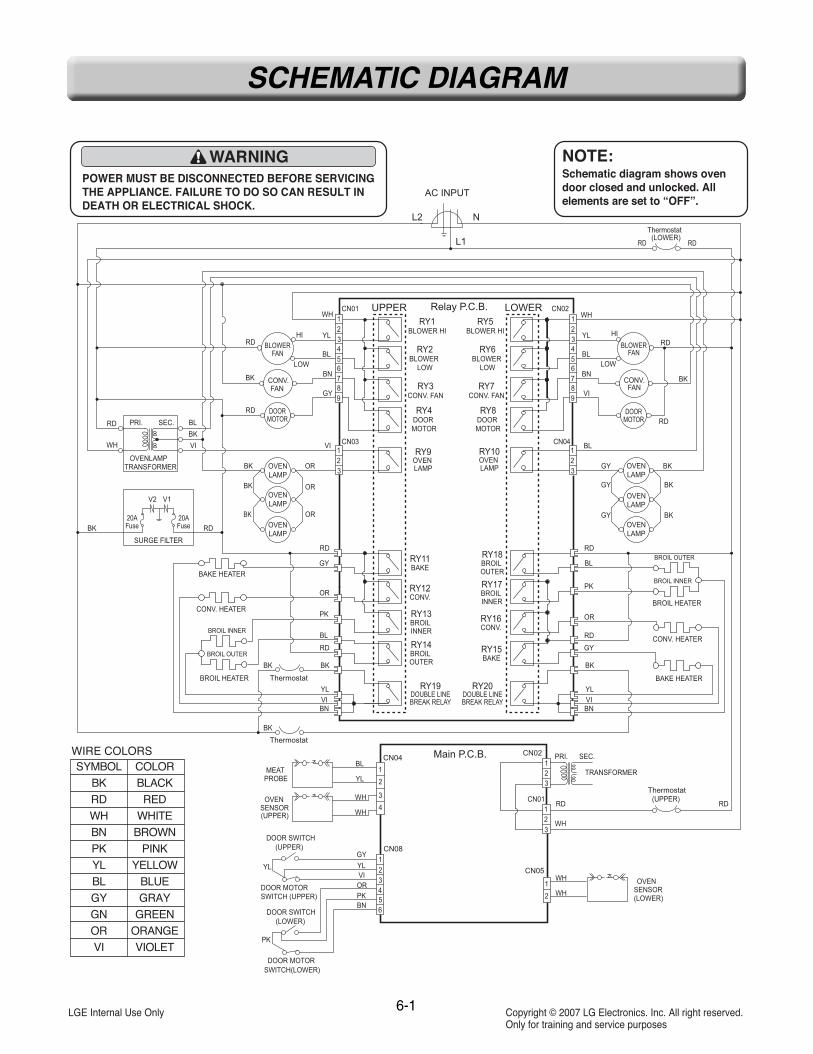
SCHEMATIC DIAGRAM - - - - - - - - - - - - - - - - - - - - - - - - - - - - - - - - - - - - - - - - - - - - - - - - - - - - - - - - - - - - - - - - - - - - - - - - - - - - - - - 6-1• Strip circuits - - - - - - - - - - - - - - - - - - - - - - - - - - - - - - - - - - - - - - - - - - - - - - - - - - - - - - - - - - - - - - - - - - - - - - - - - - - - - - - - - - - - - - - - - - 6-2 ~ 6-5
EXPLODED VIEW - - - - - - - - - - - - - - - - - - - - - - - - - - - - - - - - - - - - - - - - - - - - - - - - - - - - - - - - - - - - - - - - - - - - - - - - - - - - - - - 7-1 ~ 7-6
REPLACEMENT PARTS LIST - - - - - - - - - - - - - - - - - - - - - - - - - - - - - - - - - - - - - - - - - - - - - - - - - - - - - - - - - - - - - - 8-1 ~ 8-3

1-1
GENERAL
READ ALL INSTRUCTIONS BEFORE USEREAD ALL INSTRUCTIONS BEFORE USERead and follow all instructions before using your oven to prevent the risk of fire, electric shock, injury to person, ordamage when using the range. This guide don’t cover all possible conditions that may occur. For further assistancecontact your service agent or manufacturer.
This is the safety alert symbol. This symbol alerts you to potential hazards that can kill or hunt youand others. All safety messages will follow the safety alert symbol and either the word “WARNING”or “CAUTION”. These word means :
This symbol will alert you to hazards or unsafe practices which could causeserious bodily harm or death.WARNING
This symbol will alert you to hazards or unsafe practices which could causebodily injury or property damage.CAUTION
WARNING• NEVER use your appliance for warming or heating the room.• DO NOT use water on grease fires.- Turn off the oven to avoid spreading the flames. Smother the fire by closing the oven door or use dry chemical,
baking soda, or foam-type extinguishers.• Use only dry pot holders. - Moist or damp pot holders on hot surfaces may result in burns from steam. Do not let the pot holder touch hot
heating elements. Do not use a towel or other bulky cloth.• Storage in or on appliance.- Flammable materials should not be stored in an oven or near surface elements.• Wear proper apparel.- Loose-fitting or hanging garments should never be worn while using the appliance.• DO NOT place aluminum foil directly on the oven bottom.• Children should be kept away from the oven.- Accessible parts may become hot when the broil is use.• DISCONNECT power supply cord from the outlet before servicing. • Replace all panels and parts before operating.• RECONNECT all grounding devices.- Failure to do so can result in severe personal injury, death or electrical shock.• DO NOT Touch when the oven operates. - The interior parts will be very hot. • ELECTRIC SHOCK HAZARD- Unit must be disconnected from electrical outlet when making repairs, replacements, adjustments. Replace all
panels before operating oven. Failure to do so can result in death or electrical shock.
CAUTION• DO NOT leave children alone.- Children should not be left alone or unattended in area where appliance is in use.- Children should never be allowed to sit or stand on any part of the appliance.• DO NOT leave small children unattended near the appliance.- During the self-cleaning cycle, the outside of the oven can become very hot to touch.• Be careful when you work on the electric oven handling the sheet metal part.- Sharp edge may be present and you can cut yourself.• Be careful not to bend the fan blade.• The door is very heavy. Be careful when removing and lifting door. Do not lift the
door by the handle.

1-2
GENERAL
READ ALL INSTRUCTIONS BEFORE USEREAD ALL INSTRUCTIONS BEFORE USE
SAFETY PRECAUTIONS• Be certain your appliance is properly installed
and grounded by a qualified technician.• Do not repair or replace any part of the
appliance unless specifically recommended inthe manual.
• All other servicing should be referred to aqualified technician.
• Always disconnect power to appliance beforeservicing by unplugging, removing the fuse orswitching off the circuit breaker.
• DO NOT TOUCH HEATING ELEMENTS ORINTERIOR SURFACES OF OVEN.Heating elements may be hot even though theyare dark in color. Interior surfaces of an ovenbecome hot enough to cause burns. During andafter use, do not touch or let clothing or otherflammable materials contact heating elementsor interior surfaces of oven until they have hadsufficient time to cool. Other surfaces of theappliance may become hot enough to causeburns. Among these surfaces are oven ventopenings and surfaces near these openings,oven doors, and windows of oven doors.
• Use Care When Opening Door.Let hot air or steam escape before you removeor replace food in the oven
• Do Not Heat Unopened Food Containers.Build-up of pressure may cause container toburst and result in injury.
• Keep Oven VentDucts Unobstructed.The oven vent couldbecome hot duringoven use. Never blockthis vent and neverplace plastic or heat-sensitive items on ornear the vent.
NOTE:For proper operation vent trim must be installed.
• Be certain all packing materials are removedfrom the appliance before operating.Keep plastics, clothes, and paper away fromparts of the appliance that may become hot.
• DO NOT force the door open.This can damage the automatic door lockingsystem. Use care when opening the oven doorafter the self-cleaning cycle. Stand to the side ofthe oven when opening the door to allow hot airor steam to escape. The oven may still beVERY HOT.
• DO NOT use a steel-wool pad.It will SCRATCH the surface.
• DO NOT use harsh etching, abrasivecleaners or sharp metal scrapers to cleanthe oven door glass since they can scratchthe surface.It may result in shattering of the glass.
• Be careful when removing and lifting the door.• DO NOT lift the door by the handle.
The door is very heavy.• DO NOT step or sit on oven door.
Be sure to follow proper installation instructions.
ELECTRICAL SAFETY• Protective Liners. Do not use aluminum foil or
any other material to line the oven bottoms.Improper installation of these liners may resultin a risk of electric shock or fire.
• Do Not allow aluminum foil or meat probe tocontact heating elements.
Metal bottomtrim (Vent)
WARNING
• DO NOT place aluminum foil directlyon the oven bottom.
Aluminum foil

1-3
GENERAL
READ ALL INSTRUCTIONS BEFORE USEREAD ALL INSTRUCTIONS BEFORE USE
• Before replacing your oven light bulb,switch off the electrical power to the oven atthe main fuse or circuit breaker panel. Failure to do so can result in severe personalinjury, death, or electrical shock.
• DO NOT line the oven walls, racks, bottom,or any other part of the oven with aluminumfoil or any other material.Doing so will disrupt heat distribution, producepoor baking results and cause permanentdamage to the oven interior (aluminum foil willmelt to the interior surface of the oven.)
SAFETY DURING USE• Oven Racks. Always place oven racks in
desired position while oven is cool.• Always use pot holders or oven mitts when
removing food from the oven.You can be burned because cookware andplates will be hot.
• Use caution with the TIMED BAKE orDELAYED TIMED BAKE features. Use theautomatic timer when cooking cured orfrozen meats and most fruits andvegetables. Foods that can easily spoil,such as milk, eggs, fish, meat or poultry,should be chilled in the refrigerator first.Even when chilled, they should not stand inthe oven for more than 1 hour beforecooking begins, and should be removedpromptly when cooking is completed. Eating spoiled food can result in sickness fromfood poisoning.
• Should an oven fire occur, leave the ovendoor closed and turn the oven off. If the firecontinues, throw baking soda on the fire oruse a fire extinguisher.
• DO NOT put water or flour on the fire. Flour may be explosive and water can cause agrease fire to spread and cause personal injury.
• DO NOT use the broiler pan without the grid.DO NOT cover the grid with aluminum foil.
CHILD SAFETY
WARNING• Children should be kept away
from the oven.• Accessory parts will become hot
when the broiler is in use.
CAUTION• Children should not be left alone
or unattended in area whereappliance is in use. Childrenshould never be allowed to sit orstand on any part of theappliance.
CAUTION• DO NOT leave small children
unattended near the appliance.During the self-cleaning cycle, theoutside of the oven can become very hotto the touch.

1-4
GENERAL
READ ALL INSTRUCTIONS BEFORE USEREAD ALL INSTRUCTIONS BEFORE USE
SAFETY WHEN CLEANING• Do Not Clean Door Gasket. The door gasket is
essential for a good seal. Care should be takennot to rub, damage, or move the gasket.
• Do Not Use Oven Cleaners. No commercialoven cleaner or oven liner protective coating ofany kind should be used in or around any partof the oven.
• Before self cleaning the oven. Remove broilerpan, all oven racks, meat probe and any otherutensils from the oven cavity.
• Never keep pet birds in the kitchen. Thehealth of birds is extremely sensitive to thefumes released during an oven self-clean cycle.Fumes may be harmful or fatal to birds. Movebirds to well-ventilated room.
• Important Instruction. In the event the selfclean error code F is displayed, and errormelody sounds, the oven is malfunctioning inthe self clean mode. Switch off the electricalpower to the main fuse or breaker and haveserviced by a qualified technician.
• Make sure oven lights are cool beforecleaning.
• DO NOT block the oven vent duringoperation.This can damage the electric parts of the oven.Air must be able to move freely. The metalbottom trim (vent) should be properlyassembled on the front bottom of oven beforeinstalling the oven door.
Metal bottom trim(Vent)

1-5
GENERAL
MODEL & SERIAL NUMBER LABEL AND MODEL & SERIAL NUMBER LABEL AND TECH SHEET LOCATECH SHEET LOCATIONTION
The Model/Serial Number label and Tech Sheet locations are shown below.
Model & Serial Number Location
Tech Sheet Location

Product Specification List
No Items Specifications Remarks
1
2
3
4
5
6
7
8
9
10
11
12
13
14
15
16
17
18
Model name
Rating power source
Heat source
Max power
Max input current
Rating power consumption
& Rating input current
Efficiency
Control style
Display
Power control range
Capacity (Overall, W×H×D)
Capacity (Usable)
Cut out size (W×H×D)
Unit Dimension
Net Weight
Packing size
Packing weight
Stack height
North American market
Single phase & 4-wires
120/208V : 5.9 KW
Upper+Lower oven
Upper+Lower oven
Upper+Lower oven
Front ceiling area
Left & right sides
Liquid Crystal Display
At bake mode
24 1/2×17 11/16×18 5/8
23 5/8×13 9/16×17 3/16
28 1/2×51 13/16×23 1/2
29 3/4×52 1/16×24 3/8
264 lbs
33 11/16×57 7/8×30 9/16
297 lbs
LWD3081ST Built-in Double wall oven
240V~60Hz
Sheath heater & Carbon heater
7.8 KW
32.5 A
Bake 2,500W / 10.4A×2
Broil 4,000W / 16.7A×2
Convection 2,500W /10.4A×2
Lamp 12V/10W/0.8A×2
Lamp (12V/10W/0.8A×2)×2
Cooling motor 120V/41W/0.34A×2
Convection motor 120V/42W/0.65A×2
Locking motor 120V/3.5W/0.03A×2
Higher than 80%
Touch screen, glass touch & Micom
White LCD
170~550˚F (77~288˚C)
4.7 cu.ft (622×449×474 )
3.2 cu.ft (601×345×436 )
724×1,316×596
755×1,322×619
120 Kg
855×1,470×776
135 Kg
2 levels
1-6
GENERAL
SPECIFICASPECIFICATIONSTIONS
2-1
USING YOUR OVEN
GENERAL INFORMAGENERAL INFORMATIONTION
Rating LabelModel numbers are recorded on the rating label.Rating label is located on the lower left bottomarea of the controller. It can be seen by openingthe Upper door. Before ordering parts, write downthe correct model and serial number from ratinglabel. This avoids incorrect shipments anddelays. Please refer to parts reference materialwhen ordering replacement parts.
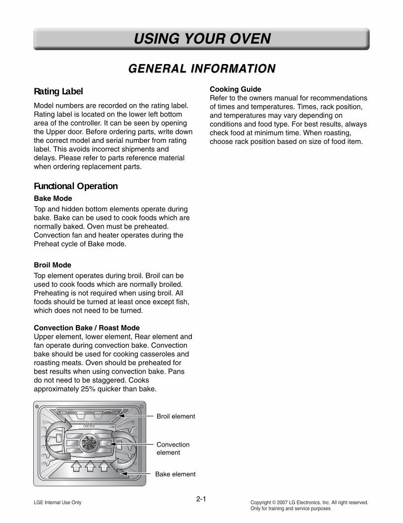
Functional OperationBake ModeTop and hidden bottom elements operate duringbake. Bake can be used to cook foods which arenormally baked. Oven must be preheated.Convection fan and heater operates during thePreheat cycle of Bake mode.
Broil ModeTop element operates during broil. Broil can beused to cook foods which are normally broiled.Preheating is not required when using broil. Allfoods should be turned at least once except fish,which does not need to be turned.
Convection Bake / Roast ModeUpper element, lower element, Rear element andfan operate during convection bake. Convectionbake should be used for cooking casseroles androasting meats. Oven should be preheated forbest results when using convection bake. Pansdo not need to be staggered. Cooksapproximately 25% quicker than bake.
Cooking GuideRefer to the owners manual for recommendationsof times and temperatures. Times, rack position,and temperatures may vary depending onconditions and food type. For best results, alwayscheck food at minimum time. When roasting,choose rack position based on size of food item.
Broil element
Convectionelement
Bake element

2-2
USING YOUR OVEN
CONTROL PCONTROL PANEL FEAANEL FEATURESTURES
1. UPPER LIGHT: Use to turn the upper oven lights on and off.2. LOWER LIGHT: Use to turn the lower oven lights on and off.3. UPPER OVEN: Use to activate the upper oven for the main
menu selection.4. LOWER OVEN: Use to activate the lower oven for the main
menu selection.5. START: Use to start all oven features. Activate the
CONTROL LOCK for 3 seconds holding.6. TIMER ON/OFF: Use to set or cancel the timer.7. UPPER CLEAR/OFF: Use to stop cooking or cancel the
setting of the upper oven.8. LOWER CLEAR/OFF: Use to stop cooking or cancel the
setting of the lower oven.9. Touch Screen: Show the time of day, main menu, and oven
temperature; whether the oven is the bake, broil or self-cleaning mode; and the times set for the timer or automaticoven operations. The display panel will go into a “sleep”mode if no activity. Touch the display once to activate andagain to make your selection.
10. Bake: Use to select the normal bake mode.11. Broil: Use to set the variable broil mode.12. Roast: Use to select the normal roast mode.13. Conv. Bake: Use to select the convection bake mode.14. Crisp Conv.: Use to select the crisp convection mode.15. Conv. Roast: Use to select the convection roast mode.16. Recipe Bank: Use to recall the recipe category of gourmet
food.17. Proof/Warm: Use to proof bread / Use to hold food warm.18. Healthier Roast: Use to select the healthier roast mode.19. My Menu: Use to save or recall the favorite 10 cook mode.20. Set up: Use to change the special settings.21. Self Clean: Use to select the self-cleaning cycle
NOTE:• Press CLEAR/OFF pad. Allow the oven to cool for one hour.Put back into operation.
• If the function error code repeats, disconnect the powerto the oven and call for service.
• If the oven was set for a timed oven operation and a powerfailure occurred, the clock and all programmed functions mustbe reset.
• The time of day will flash and PF will appear in the displaywhen there has been a power failure.
1 3 9 5
642 8
7
10 11 12 19
13 14 15 211716 18 20
READ THE INSTRUCTIONS CAREFULLY BEFORE USING THE OVEN. For satisfactory use of youroven, become familiar with the various features and functions of the oven as described below.

2-3
USING YOUR OVEN
1. SETTING THE INITIAL CONTROL1) LG logo display 8 seconds. - Initial display
(Power Failure or Reset)First, Select Language, and set clock time, andthen the oven can be used. If power failure occurs, the oven will rememberyour language selection however you will stillneed to set the time of day.
2) Key Function, General Usage While selectingany function, an appropriate key input sequencemust be followed. In case of an inappropriateinput sequence the key error beeps sound.Numeric key are used while entering data(temperature and time) for cooking.
2. START, CLEAN/OFF1) START key to start oven2) CLEAR/OFF key to cancel a program during
cooking or erase during programming.
3. OVEN LIGHT [UPPER / LOWER]1) Requirement: The Oven Light is used to turn on
or off the oven light.2) Key Input Process: Oven Light-ON/OFF toggle
operation. If the Oven Light is on by pressing oven light key,the light is on even if the door is closed. Ovenlight key can be operated while door opens.
3) Exception: Oven light will not operate during aself clean cycle. Once self clean iscomplete the oven light will notoperate until oven cools down.
4. TIMER1) Requirement: The timer works like an alarm clock
that will continuously beep until turned off. Theoven can fully operate during the use of the timer.
- Setting Limit : 11Hour : 59Min
2) Min and Sec Setting;
3) Hour and Min setting
4) When the set time has elapsed, “Timer End” isdisplayed. Timer alarm melody will sound every15 seconds until TIMER is pressed. Press timerkey in order to cancel running timer or clear timerend alarm. The time less than 1hour is displayedin min and sec on timer operation.
5. CONTROL LOCKOUT1) The START key controls the Control Lock
feature. The Control Lock feature automaticallylocks most oven controls from being turned ON.It does not disable the timer and the interior ovenlight. The Control Lock feature will cancel thecooking mode and will lock the oven controls atany time when you activate this feature.
2) Key Input Process : START (for 4 seconds)
Lock melody will sound.
3) To unlock the control, press START (for 4 seconds)
Unlock melody will sound.
6. SET UP (8 DIFFERENT CATEGORIES) 1) Language Selection
1. Requirement: The scroll display can be showneither in English/Spanish/French.
2. Key Input Process
3. CLEAR to reject the change.
2) Temperature Selection unit1. Requirement: The oven control can be
programmed to display temperatures inFahrenheit or Centigrade. The oven has beenpreset at the factory to display in Fahrenheit.
2. Key Input Process
3. CLEAR to reject the change.
TIMER NUMERIC (Set thedesired time-min and sec) TIMER
TIMER TIMER NUMERIC (Set thedesired time-hour and min) TIMER
Set Up Select language OK
Set Up Select Temp.Unit OK

2-4
USING YOUR OVEN
3) Display brightness1. Requirement: LCD Display Brightness
adjustment2. Key Input Process
3. CLEAR to reject the change.
4) Sound Volume Loud/Normal/Mute1. Requirement: When want to reduce or
increase the volume.2. Key Input Process
3. CLEAR to reject the change.4. Exception : Error Alarm, Preheat Alarm, Timer
End Alarm – If Mute, Normal Beep Sounds.
5) Convection Auto Conversion1. Requirement: When using convection, Auto
conversion will automatically convert anentered regular baking temperatures toconvection baking temperatures.
2. Key Input Process
3. CLEAR to reject the change.
6) Temperature Adjustment1. To change the oven temperature during use
follow the steps below.
Fahrenheit : (-)35 ~ (+)35Centigrade : (-)19 ~ (+)19
2. Key Input Process
3. CLEAR to reject the change.
* Note: This adjustment is available for Bake,Roast, Convection Bake, Roast, Crisp Conv.Healthier Roast. Temperature Adjustment can beconfirmed by measuring real Oven CavityTemperature.
7) Clock Time1. Requirement: The clock key is used to set the
clock in idle mode. The clock can be set to 12or 24 hour format. am and pm can be set in 12hours.When the oven is initially plugged in, orwhen the power supply to the oven isinterrupted ?
2. Key Input Process
3. CLEAR to cancel the clock setting.
8) Reset1. Requirement: Setting Value will be default
value.2. Key Input Process
3. CLEAR to reject the change.
7. BAKE
8. TIMED COOK, DELAYED TIMED COOK
Set Up Select Brightness OK
Set Up Select Volume OK
Set Up Select Yes, No OK
Set Up Select mode OK
Set Up Adjust Temperature OK
Set Up Selecthours set clock time
select am, pm OK
BAKE Desired Temperature START
BAKEBROIL
DesiredTemperature START
START DesiredTemperature START
Cook &warm
STARTTIME
Desiredstart time START
Cook &warm

9. BROIL
10. ROAST
11. CONVECTION BAKE
12. CRISP CONVECTION
13. CONVECTION ROAST
14. RECIPE BANK
15. PROOF/WARM
16. HEALTHIER ROAST
* Note: The meat probe must be used in thisfeature.(refer to the HEALTHIER ROASTING CHART.)
17. My MENU
18. OPTION
19. SELF CLEAN
2-5
USING YOUR OVEN
ROAST DesiredTemperature START
Conv.Bake
DesiredTemperature START
CrispConv.
DesiredTemperature START
Conv.Roast
DesiredTemperature START
Proof Desired Cook time START
Warm SelectedTemp. START
My Menu create Select cookmenu
Desiredtemp Option Enter
My menu
Start Time
Desired Starttime START
Select My menu START
Broil Desired Broil Full / Center
Desired Temp High / Med / Low START
HealthierRoast
Selected foodcategory
DesiredTemperature START
Recipe Select Recipes
Correspondingmenu START
Option Temp Cook timeStart time OK
Option Select clean level
: Light → 2Hours: Normal →3Hours
START

This section instructs you on how to service each component inside the range. The components and theirlocations are shown below.
COMPONENT LOCACOMPONENT LOCATIONSTIONS
Lower Door Switch
Oven Sensor
Convection Motor
Convection Heater
Upper Door Switch
Upper Oven Light
Main PCB
Display PCB
Side Key PCB
Low Voltage Transformer
Hinge Hanger
Hinge Hanger
Upper Door LatchAssembly
Lower Door LatchAssembly
Lower Oven Light
Bake Heater
Broil HeaterOven Sensor
Convection Motor
Convection Heater
Bake Heater
3-1
DISASSEMBLY INSTRUCTIONS

3-2
DISASSEMBLY INSTRUCTIONS(UPPER)
1. Turn off the electrical supply going to the oven.2. Open the upper door assembly.3. Remove the 3 screws from below the control
panel.
6. Disconnect the 8EA connector from PCB assembly(CN01, CN02, CN03, CN04, CN05, CN08, CN11,CN12) and separate control panel carefully.
7. You can see the interior of electric parts chamber.
8. To remove the following components follow thesequence below.Controller LVT, Relay PCB, Door lock motor,Halogen lamp LVT, Surge filter can be servicedwithout removing the oven.
1) To remove the PCB Low voltage transformer.Remove the 1 screw.
REPLACING THE CONTROL PREPLACING THE CONTROL PANEL AND RELAANEL AND RELATED COMPONENTS TED COMPONENTS
WARNING
• ELECTRIC SHOCK HAZARD- Unit must be disconnected from electricaloutlet when making repairs, replacements,adjustments. Replace all panels beforeoperating oven. Failure to do so can resultin death or electrical shock.
CAUTION• Be careful when you work on the
electric oven handling the sheetmetal part.
4.Close the upper door assembly.5. Lift the control panel off from the guide hooks
and top trim. Tilt the control panel down. Hinge panel into slots on main body and letcontrol panel rest.
Guide holeGuide holeGuide holeGuide holeGuide holeGuide holeGuide holeGuide holeGuide holeGuide holeGuide holeGuide holeGuide holeGuide holeGuide holeGuide holeGuide holeGuide hole
HookHookHookHookHookHookHookHookHookHookHookHookHookHookHookHookHookHook
CN03CN03CN03CN03CN03CN03CN03CN03CN03CN03CN03CN03CN03CN03CN03CN03CN03CN03
CN05CN05CN05CN05CN05CN05CN05CN05CN05CN05CN05CN05CN05CN05CN05CN05CN05CN05 CN12CN12CN12CN12CN12CN12CN12CN12CN12CN12CN12CN12CN12CN12CN12CN12CN12CN12
CN11CN11CN11CN11CN11CN11CN11CN11CN11CN11CN11CN11CN11CN11CN11CN11CN11CN11
CN08CN08CN08CN08CN08CN08CN08CN08CN08CN08CN08CN08CN08CN08CN08CN08CN08CN08 CN04CN04CN04CN04CN04CN04CN04CN04CN04CN04CN04CN04CN04CN04CN04CN04CN04CN04
CN02CN02CN02CN02CN02CN02CN02CN02CN02CN02CN02CN02CN02CN02CN02CN02CN02CN02
CN01CN01CN01CN01CN01CN01CN01CN01CN01CN01CN01CN01CN01CN01CN01CN01CN01CN01CN01CN01CN01CN01CN01CN01CN01CN01CN01CN01CN01CN01CN01CN01CN01CN01CN01CN01
RelayPCB
RelayPCB
RelayPCBRelayPCBRelayPCBRelayPCBRelayPCBRelayPCBRelayPCBRelayPCBRelayPCBRelayPCBRelayPCBRelayPCBRelayPCB
RelayPCB
RelayPCBRelayPCB
Door lockmotor
Door lockmotor
Door lockmotor
Door lockmotor
Door lockmotor
Door lockmotor
Door lockmotor
Door lockmotor
Door lockmotor
Door lockmotor
Door lockmotor
Door lockmotor
Door lockmotor
Door lockmotor
Door lockmotor
Door lockmotor
Door lockmotor
Door lockmotor
Halogen lampLVT
Halogen lampLVT
Halogen lampLVT
Halogen lampLVT
Halogen lampLVT
Halogen lampLVT
Halogen lampLVT
Halogen lampLVT
Halogen lampLVT
Halogen lampLVT
Halogen lampLVT
Halogen lampLVT
Halogen lampLVT
Halogen lampLVT
Halogen lampLVT
Halogen lampLVT
Halogen lampLVT
Halogen lampLVT
ControllerLVT
ControllerLVT
ControllerLVT
ControllerLVT
ControllerLVT
ControllerLVT
ControllerLVT
ControllerLVT
ControllerLVT
ControllerLVT
ControllerLVT
ControllerLVT
ControllerLVT
ControllerLVT
ControllerLVT
ControllerLVT
ControllerLVT
ControllerLVT
3-3
DISASSEMBLY INSTRUCTIONS(UPPER)
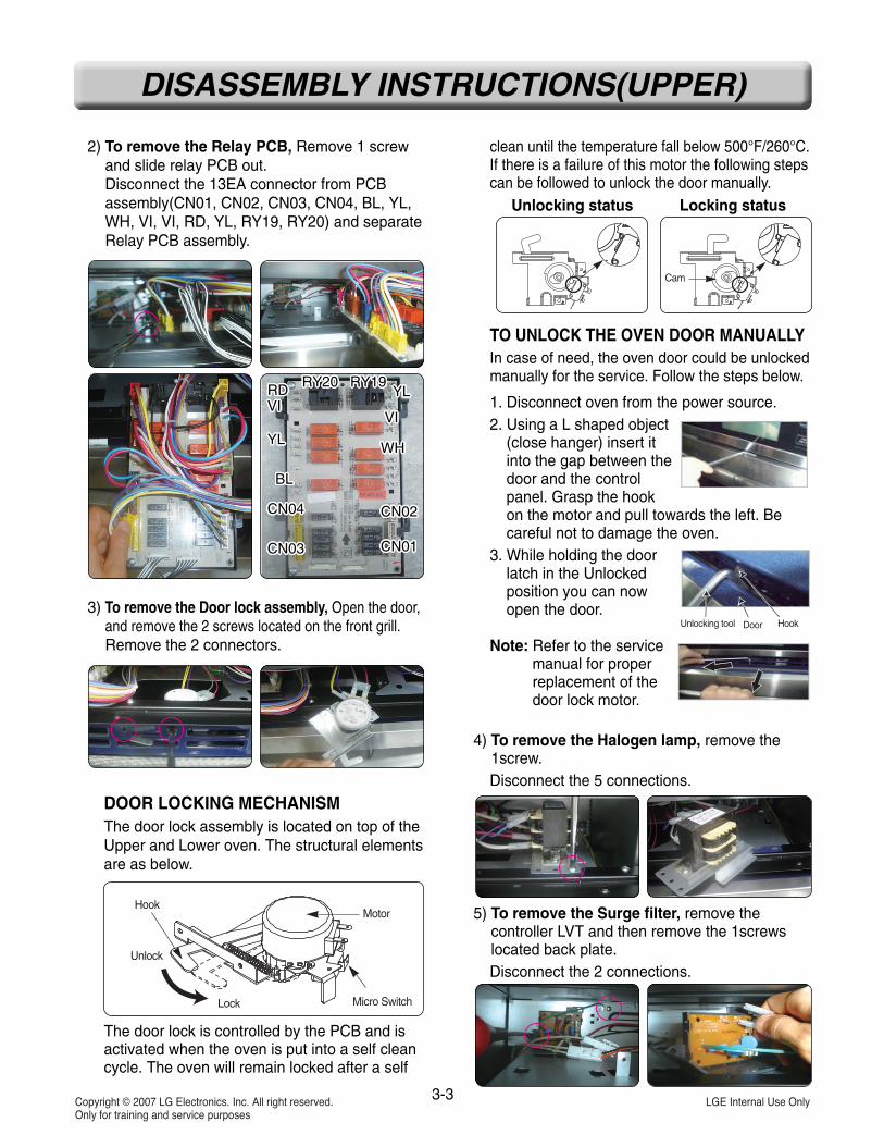
2) To remove the Relay PCB, Remove 1 screwand slide relay PCB out.Disconnect the 13EA connector from PCBassembly(CN01, CN02, CN03, CN04, BL, YL,WH, VI, VI, RD, YL, RY19, RY20) and separateRelay PCB assembly.
3) To remove the Door lock assembly, Open the door,and remove the 2 screws located on the front grill.Remove the 2 connectors.
DOOR LOCKING MECHANISMThe door lock assembly is located on top of theUpper and Lower oven. The structural elementsare as below.
The door lock is controlled by the PCB and isactivated when the oven is put into a self cleancycle. The oven will remain locked after a self
clean until the temperature fall below 500°F/260°C.If there is a failure of this motor the following stepscan be followed to unlock the door manually.
TO UNLOCK THE OVEN DOOR MANUALLYIn case of need, the oven door could be unlockedmanually for the service. Follow the steps below.
1. Disconnect oven from the power source.2. Using a L shaped object
(close hanger) insert itinto the gap between thedoor and the controlpanel. Grasp the hookon the motor and pull towards the left. Becareful not to damage the oven.
3. While holding the doorlatch in the Unlockedposition you can nowopen the door.
Note: Refer to the servicemanual for properreplacement of thedoor lock motor.
4) To remove the Halogen lamp, remove the1screw.Disconnect the 5 connections.
5) To remove the Surge filter, remove thecontroller LVT and then remove the 1screwslocated back plate.Disconnect the 2 connections.
RDVI
YL
BL
CN04
CN03
RDVI
YL
BL
CN04
CN03
RDVI
YL
BL
CN04
CN03
RDVI
YL
BL
CN04
CN03
RDVI
YL
BL
CN04
CN03
RDVI
YL
BL
CN04
CN03
RDVI
YL
BL
CN04
CN03
RDVI
YL
BL
CN04
CN03
RDVI
YL
BL
CN04
CN03
RDVI
YL
BL
CN04
CN03
RDVI
YL
BL
CN04
CN03
RDVI
YL
BL
CN04
CN03
RDVI
YL
BL
CN04
CN03
RDVI
YL
BL
CN04
CN03
RDVI
YL
BL
CN04
CN03
RDVI
YL
BL
CN04
CN03
RDVI
YL
BL
CN04
CN03
RDVI
YL
BL
CN04
CN03
RY20 RY19RY20 RY19RY20 RY19RY20 RY19RY20 RY19RY20 RY19RY20 RY19RY20 RY19RY20 RY19RY20 RY19RY20 RY19RY20 RY19RY20 RY19RY20 RY19RY20 RY19RY20 RY19RY20 RY19RY20 RY19YL
VI
WH
CN02
CN01
YL
VI
WH
CN02
CN01
YL
VI
WH
CN02
CN01
YL
VI
WH
CN02
CN01
YL
VI
WH
CN02
CN01
YL
VI
WH
CN02
CN01
YL
VI
WH
CN02
CN01
YL
VI
WH
CN02
CN01
YL
VI
WH
CN02
CN01
YL
VI
WH
CN02
CN01
YL
VI
WH
CN02
CN01
YL
VI
WH
CN02
CN01
YL
VI
WH
CN02
CN01
YL
VI
WH
CN02
CN01
YL
VI
WH
CN02
CN01
YL
VI
WH
CN02
CN01
YL
VI
WH
CN02
CN01
YL
VI
WH
CN02
CN01
Micro Switch
Motor
Lock
Unlock
Hook
Cam
Unlocking tool Door Hook
Unlocking status Locking status

1. Turn off the electrical supply going to the oven.2. Remove the Upper/Lower door assembly.3. To remove the following components follow the
sequence below.Broil element, Convection element, Fan blade,Oven thermistor, Halogen lamp can be servicedwithout removing the oven.
1) To remove the broil element:a. Remove the 4 screws from the front and rear
brackets.
b. Pull the element forward so that you canaccess the terminals and disconnect the wires.
2) To remove the convection element:a. Remove the 4 screws on the convection fan
cover.
3-4
DISASSEMBLY INSTRUCTIONS(UPPER/LOWER)
REPLACING OVEN CAREPLACING OVEN CAVITY COMPONENTSVITY COMPONENTS
Halogen lamp 3EA
Broil elements
Convectionelements
Blade fan
Broil elements
Convectionelements
Blade fan
Broil elements
Convectionelements
Blade fan
Broil elements
Convectionelements
Blade fan
Broil elements
Convectionelements
Blade fan
Broil elements
Convectionelements
Blade fan
Broil elements
Convectionelements
Blade fan
Broil elements
Convectionelements
Blade fan
Broil elements
Convectionelements
Blade fan
Broil elements
Convectionelements
Blade fan
Broil elements
Convectionelements
Blade fan
Broil elements
Convectionelements
Blade fan
Broil elements
Convectionelements
Blade fan
Broil elements
Convectionelements
Blade fan
Broil elements
Convectionelements
Blade fan
Broil elements
Convectionelements
Blade fan
Broil elements
Convectionelements
Blade fan
Broil elements
Convectionelements
Blade fan
OvenThermistor
OvenThermistor
OvenThermistor
OvenThermistor
OvenThermistor
OvenThermistor
OvenThermistor
OvenThermistor
OvenThermistor
OvenThermistor
OvenThermistor
OvenThermistor
OvenThermistor
OvenThermistor
OvenThermistor
OvenThermistor
OvenThermistor
OvenThermistor
WARNING
• ELECTRIC SHOCK HAZARD- Unit must be disconnected from electricaloutlet when making repairs, replacements,adjustments. Replace all panels beforeoperating oven. Failure to do so can resultin death or electrical shock.
CAUTION• Be careful when you work on the
electric oven handling the sheetmetal part.

3-5
DISASSEMBLY INSTRUCTIONS(UPPER/LOWER)
b. Remove the 4 convection element screws.(The convection element is fragile. Careshould be taken to avoid any risk of injury)
c. Pull the element forward so that you canaccess the terminals and disconnect the wires.
3) To remove Blade fan(Convection fan) a. Remove nut by screwing clockwise.
(be careful fan blade is bent easily)b. Fan blade can be replaced from inside oven.
4) To remove the halogen lamp & socket assemblya. There are three halogen lamp & socket
assembly in the oven cavity.
b. Insert a flat bladescrewdriver into theguide hole and pull off.
C. Replace the halogenlamp, then reinstall theglass cover.
* Note :The above instructions can be used for replacingany of the halogen bulbs in either oven.
5) To remove oven temperature sensors,Remove the 2 screws from the temperaturesensor bracket.Pull the temperature sensor forward andremove the connector.
MountingScews(3ea)
Fan CoverScews(4ea)
OuterInnerCavity
ConvectionHeater
Fan BladeFan Cover
Washer
Bushing
Nut
Fan Motor
CAUTIONBe careful not to bend the fan blade.
Halogen lamp 3EAHalogen lamp 3EAHalogen lamp 3EAHalogen lamp 3EAHalogen lamp 3EAHalogen lamp 3EAHalogen lamp 3EAHalogen lamp 3EAHalogen lamp 3EAHalogen lamp 3EAHalogen lamp 3EAHalogen lamp 3EAHalogen lamp 3EAHalogen lamp 3EAHalogen lamp 3EAHalogen lamp 3EAHalogen lamp 3EAHalogen lamp 3EA

3-6
DISASSEMBLY INSTRUCTIONS(UPPER)
REPLACING OTHER ELECTRICAL COMPONENTSREPLACING OTHER ELECTRICAL COMPONENTS
1. Turn off the electrical supply going to the oven.2. Pull the oven away from the wall cabinet so that
you can access upper panel.3. Remove the upper panel, there are 3 total pieces
(13 screws).
4. Vent motor, Thermal Limiter, and Door switch canbe serviced here.
1) To remove the vent motor, remove the 2 screws and disconnect connector.
CONTROLLER PARTS
Vent motor Thermal limiter
Door switchDoor switchDoor switchDoor switchDoor switchDoor switchDoor switchDoor switchDoor switchDoor switchDoor switchDoor switchDoor switchDoor switchDoor switchDoor switchDoor switchDoor switch
Section 2
Section 3
Section 1
WARNING
• ELECTRIC SHOCK HAZARD- Unit must be disconnected from electricaloutlet when making repairs, replacements,adjustments. Replace all panels beforeoperating oven. Failure to do so can resultin death or electrical shock.
CAUTION• Be careful when you work on the
electric oven handling the sheetmetal part.

3-7
DISASSEMBLY INSTRUCTIONS(UPPER)
COOLING FAN (BLOWER)• Self Clean Mode: The cooling fans can
operate at 2 different speeds based ontemperature. If the temp is above482°F/250°C the fans will operate on high. Iftemp is below 482°F/250°C the fans willoperate on low.
• Normal Cooking Mode: If either upper oven orlower oven temperature reaches212°F/100°C, the cooling fans will operate atlow speed at a time.
2) To remove thermal disk, remove the 1 screwand remove the 2 wires.
THERMAL LIMITER• To shut down the control power transformer
The upper thermostat is located in front of theupper cooling fan. It opens at 356°F/180°Cand closes when the oven temperature coolsbelow 14°F/-10°C.The lower thermostat is located next to lowerbake element. It opens at 320°F/160°C andcloses when the oven temperature coolsbelow 14°F/-10°C.
3) To remove door switch, Remove the 1 screw
from the top right panel
4) Squeeze tabs on switch and slide through thefront. Disconnect the wires from terminals.
6. To remove the Thermal limiter, Convection motor,and Bake Element from the upper oven Followthe steps as follows.Remove Upper rear cover.
Top right panelTop right panelTop right panelTop right panelTop right panelTop right panelTop right panelTop right panelTop right panelTop right panelTop right panelTop right panelTop right panelTop right panelTop right panelTop right panelTop right panelTop right panel
Thermal Limiter(Double Line Brake_Upper) Convection motor
Rear Cover(upper)
Bakeelement

3-8
DISASSEMBLY INSTRUCTIONS(UPPER)
1) To Remove Thermal Limiter (Double Line BrakeUpper), remove the screw and 2 wire leads.
THERMAL LIMITER• To shut down the heaters
The thermostats are located at the back of theoven next to each broil element and wired inseries with each Double Line Break relay. The upper oven thermostat opens at356°F/180°C and the lower oven thermostatopens at 284°F/140°C (Reclose Temp. : -31°F/-35°C).
2) To remove convection motor assemblyBefore removing the convection fan motor, firstfollow the steps for removing Convection Heater.a. Disconnect the 2 wire leads and remove the
3 screws from the motor bracket
b. Separate parts of cavity inner between cavityouter properly.(refer to the page3-5 About cavity innerdisassembly method)
3) To remove the hidden bake elementa. Remove the Vent cover, Barrier bracket.
b. Disconnect the 2 wire leads, remove theBake element cover.
c. Cut the 8 points of flange and remove theBake element cover.
MountingScews(3ea)
Fan CoverScews(4ea)
OuterInnerCavity
ConvectionHeater
Fan BladeFan Cover
Washer
Bushing
Nut
Fan Motor
Barrier bracket
Bake element cover(upper)
3-9
DISASSEMBLY INSTRUCTIONS(UPPER)
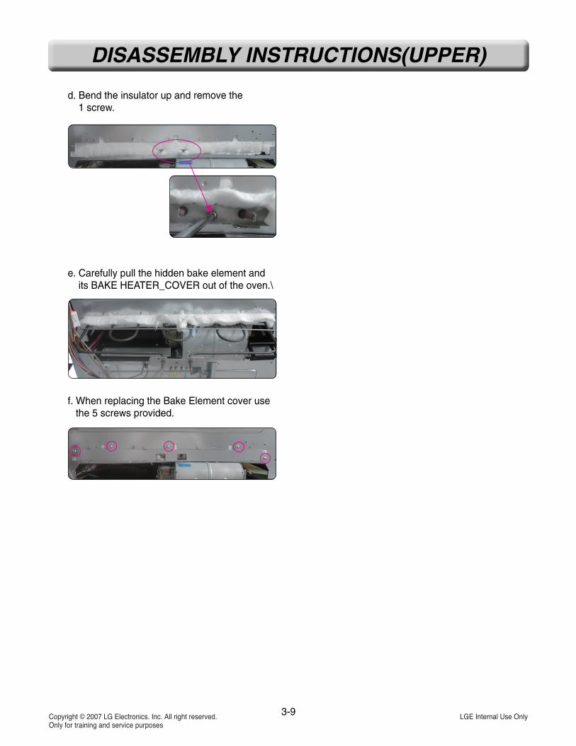
d. Bend the insulator up and remove the 1 screw.
e. Carefully pull the hidden bake element andits BAKE HEATER_COVER out of the oven.\
f. When replacing the Bake Element cover usethe 5 screws provided.

7. To remove the Thermal limiter, Convection motor,and Bake Element from the lower oven Followthe steps as follows.Remove Lower rear cover.
1) To Remove Thermal Limiter (Double Line BrakeLower), remove the screw and 2 wire leads.
THERMAL LIMITER• To shut down the control power transformer
The upper thermostat is located in front of theupper cooling fan. It opens at 356°F/180°C andcloses when the oven temperature cools below14°F/-10°C.The lower thermostat is located next to lowerbake element. It opens at 320°F/160°C andcloses when the oven temperature cools below14°F/-10°C.
2) To remove the convection motor assembly(refer to the following page 3-8)
3) To remove Thermal limiter, remove the 2wires and 1screws.
THERMAL LIMITER• To shut down the heaters
The thermostats are located at the back of theoven next to each broil element and wired inseries with each Double Line Break relay. The upper oven thermostat opens at 356°F/180°C and the lower oven thermostat opens at284°F/140°C (Reclose Temp. : -31°F/-35°C).
3-10
DISASSEMBLY INSTRUCTIONS(LOWER)
Thermal limiter(Double Line Brake_Lower) Convection motor
Bake elementThermostat
Rear cover(Lower)

3-11
DISASSEMBLY INSTRUCTIONS(LOWER)
4) To remove the hidden bake elementa. Remove the barrier bracket.
b. To remove the convection motor assembly.(refer to the following page 3-8)
8. To replace the Vent motor, Door lock motor, anddoor switch in the lower oven, you must separatethe upper oven from the lower oven. Pleasefollow the steps below.Remove Mounting side rails.
Remove screws from middle support.
1) To remove the vent motor.(refer to thefollowing page 3-6)
2) To remove the Door lock motor assembly.(refer to the following page 3-3)
3) To remove the Door switch.(refer to thefollowing page 3-7)
Middle support
Lower Doorlock motorassembly
Lower door switch Lower vent motor
Barrierbracket
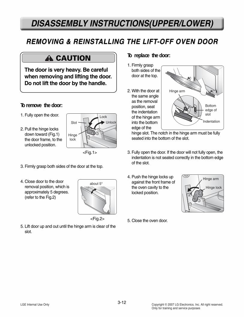
REMOVING & REINSTREMOVING & REINSTALLING THE LIFTALLING THE LIFT-OFF OVEN DOOR-OFF OVEN DOOR
To replace the door:
1. Firmly graspboth sides of thedoor at the top.
2. With the door atthe same angleas the removalposition, seatthe indentationof the hinge arminto the bottomedge of thehinge slot. The notch in the hinge arm must be fullyseated into the bottom of the slot.
3. Fully open the door. If the door will not fully open, theindentation is not seated correctly in the bottom edgeof the slot.
4. Push the hinge locks upagainst the front frame ofthe oven cavity to the locked position.
5. Close the oven door.
To remove the door:
1. Fully open the door.
2. Pull the hinge locksdown toward (Fig.1)the door frame, to theunlocked position.
3. Firmly grasp both sides of the door at the top.
4. Close door to the doorremoval position, which isapproximately 5 degrees.(refer to the Fig.2)
5. Lift door up and out until the hinge arm is clear of theslot.
Slot
Hingelock
Lock
Unlock
Hinge arm
Indentation
Bottomedge ofslot
Hinge arm
Hinge lock
<Fig.1>
<Fig.2>
CAUTIONThe door is very heavy. Be carefulwhen removing and lifting the door.Do not lift the door by the handle.
3-12
DISASSEMBLY INSTRUCTIONS(UPPER/LOWER)

1. Remove the oven door from the oven. (see page 3-11)
2. Place the oven door on a padded work surfacewith the front glass facing down.
3. Remove the 4 top door screws.
4. Remove the three bottom screw from the door liner.
5. Lift the inner assembly off the front glass and setit aside
6. To remove the door handle & trim.a. Remove 2 screws for handle and replace.b. Slide Door trim up and off.
7. To remove the hinge assembly :1) Remove the 2 lower liner screws (see step 3)2) Place the door liner assembly on a padded
work surface with the hinge over the edge.3) Remove the two hinge hanger screws.
4) Remove the 8 screws.
3-13
DISASSEMBLY INSTRUCTIONS(UPPER/LOWER)
REMOVING THE OVEN DOOR HANDLE & GLASSREMOVING THE OVEN DOOR HANDLE & GLASS
CAUTION• Be careful when you work on the
electric oven handling the sheetmetal part.
4 top liner screws
Hinge screwsHinge screwsHinge screwsHinge screwsHinge screwsHinge screwsHinge screwsHinge screwsHinge screwsHinge screwsHinge screwsHinge screwsHinge screwsHinge screwsHinge screwsHinge screwsHinge screwsHinge screws
Handle screws
COVER_INNER-2COVER_INNER-2COVER_INNER-2COVER_INNER-2COVER_INNER-2COVER_INNER-2COVER_INNER-2COVER_INNER-2COVER_INNER-2COVER_INNER-2COVER_INNER-2COVER_INNER-2COVER_INNER-2COVER_INNER-2COVER_INNER-2COVER_INNER-2COVER_INNER-2COVER_INNER-2
Door trimDoor trimDoor trimDoor trimDoor trimDoor trimDoor trimDoor trimDoor trimDoor trimDoor trimDoor trimDoor trimDoor trimDoor trimDoor trimDoor trimDoor trimDoor trimDoor trimDoor trimDoor trim

3-14
DISASSEMBLY INSTRUCTIONS(UPPER/LOWER)
5) Lift the COVER_INNER-2 off the door liner.6) Lift the hinge out of the door liner slot.
To remove the oven door glass assembly:
7) Lift the COVER_INNER-1 off the door liner.
8) Lift the inner oven door glass and bracketassembly out of the door liner.
COVER_INNER-1COVER_INNER-1COVER_INNER-1COVER_INNER-1COVER_INNER-1COVER_INNER-1COVER_INNER-1COVER_INNER-1COVER_INNER-1COVER_INNER-1COVER_INNER-1COVER_INNER-1COVER_INNER-1COVER_INNER-1COVER_INNER-1COVER_INNER-1COVER_INNER-1COVER_INNER-1
INNER OVEN DOOR GLASS & BRACKET

3-15
DISASSEMBLY INSTRUCTIONS(UPPER/LOWER)
REMOVING THE OVEN DOOR GASKETREMOVING THE OVEN DOOR GASKET
1. Remove oven door2. Pull the oven door gasket clips out of the liner
holes until all of the clips are removed.
3. Pull the ends of the gasket out of the liner holes.
REASSEMBLY NOTE: When reinstalling the newgasket, make sure that all of the clips are seated intheir liner holes, and that the ends of the gasket arepushed fully into their holes. Use the pointed end ofa pencil to push the gasket ends into the holes.
Door gasketDoor gasketDoor gasketDoor gasketDoor gasketDoor gasketDoor gasketDoor gasketDoor gasketDoor gasketDoor gasketDoor gasketDoor gasketDoor gasketDoor gasketDoor gasketDoor gasketDoor gasketDoor gasketDoor gasketDoor gasketDoor gasketDoor gasketDoor gasketDoor gasketDoor gasketDoor gasketDoor gasketDoor gasketDoor gasket
Gasket clipGasket clipGasket clipGasket clipGasket clipGasket clipGasket clipGasket clipGasket clipGasket clipGasket clipGasket clipGasket clipGasket clipGasket clipGasket clipGasket clipGasket clipGasket clipGasket clipGasket clipGasket clipGasket clipGasket clipGasket clipGasket clipGasket clipGasket clipGasket clipGasket clip
Liner Hole

4-1
COMPONENT TEST
NOTE:1. The most common cause for control failure is corrosion on connectors.
Therefore, disconnecting and reconnecting wires will be necessary throughout test procedures2. If this is a new product check all connections before replacing parts.
1. All test and checks should be made using a VOM or DVM having a range of at least 20,00 ohms or greater.
2. Be sure to check all connections before replacing components. Look for broken or loose wire, failedterminals or wires not fully seated into the connectors.
3. Resistance checks must be made with power disabled form oven, and with wiring harness or connectorsdisconnected.
Before testing any components, perform the following checks:
WARNING• Disconnect power supply before servicing• Replace all panels and parts before operating• Reconnect all grounding devices after servicing- Failure to do so can result in death or electrical shock
NOTE: Below Ω value were tested at room temperature (77F/25°C)
Convection Motor 1. Refer to page 3-8 for Disassembly
2. Measure the resistance (Multiple meter scale: R x 1)
Components Test procedures Results
Normal: Approximately 17 ΩReplace if: Infinite (opened)
below 5 Ω (shorted)

4-2
Door locking Motor
Door locking microswitch(normally close type)
Low VoltageTransformer - Controller
Low VoltageTransformer - Halogenlamp
1. Refer to page 3-10 for disassembly
2. Measure the resistance(Multiple meter scale: R x 1000)
1. Refer to page 3-10 for disassembly
2. Measure the resistance(Multiple meter scale: R x 1000)
1. Refer to page 3-2 for disassembly
2. Measure the resistance (Multiple meter scale: R x 1)
1. Refer to page 3-2 for disassembly
2. Measure the resistance (Multiple meter scale: R x 1)
Normal: Approximately 26 Ω ± 10%
Replace if: Infinite or below 1Ω
Normal: Approximately 9.8 Ω ± 10%
Replace if: Infinite or below 1Ω
Components Test procedures Results
NOCOM
Normal: Approximately 2550 ΩReplace if: Infinite (opened)
below 5 Ω (shorted)
Door latchopen
Door latchLocked
Continuity Infinite
NOTE: After checking for the continuity of switch, make sure to reconnect leadsproperly.

4-3
Oven Thermistor
Door switch
Oven lamp
1. Refer to page 3-5 for disassembly
2. Measure the resistance after cool down(Multiple meter scale: R x 1000)
Components Test procedures Results
1. Refer to page 3-5 for disassembly
2. Measure the resistance after cool down(Multiple meter scale: R x1)
Normal: Approximately 1090 Ω
Replace if: Infinite (opened)below 10 Ω (shorted)
Door open Door closed
Continuity Infinite
NOTE: After checking for the continuity of switch, make sure to reconnect leadsproperly.
1. Refer to page 3-7 for disassembly
2. Measure the resistance after cooling down(Multiple meter scale: R x 1)
NOTE: Ω Value should betested at room temperature(77F/25˚C)
Normal: Below 5 Ω.
Replace if: Infinite
4-4
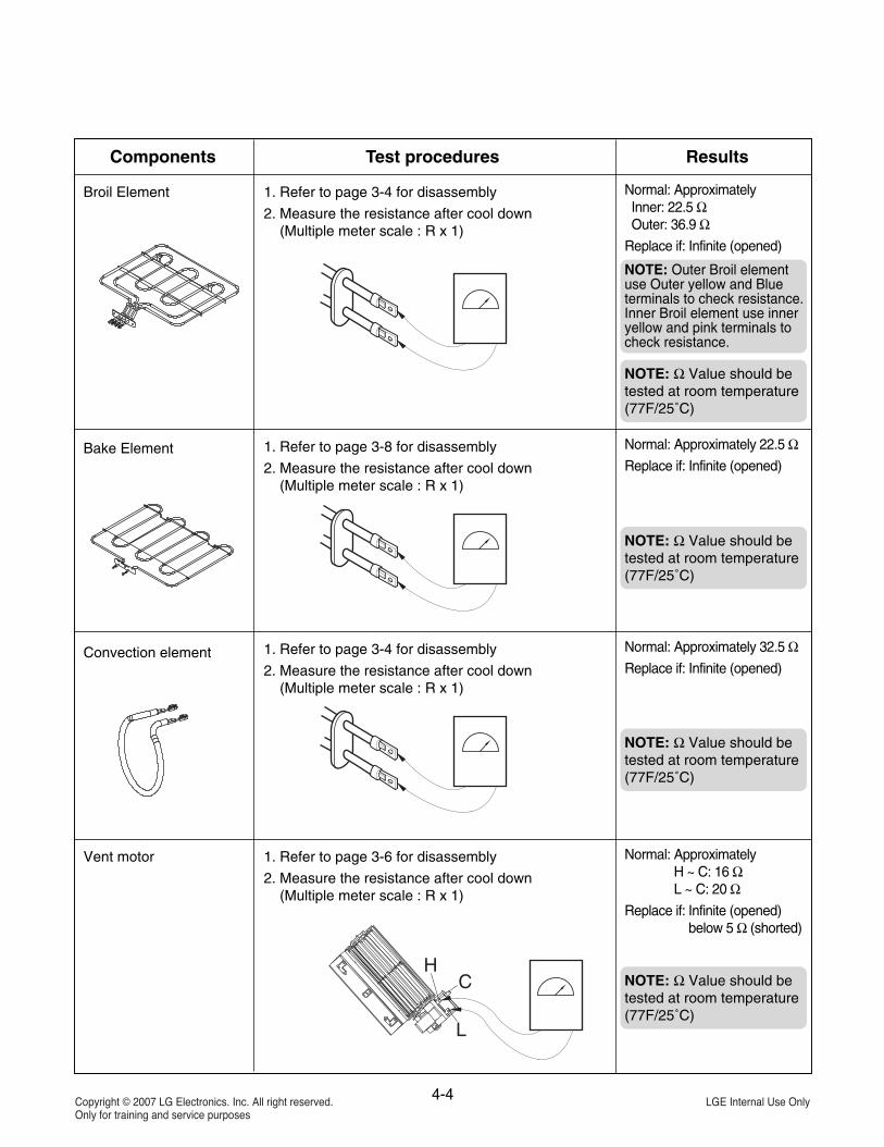
Broil Element
Bake Element
Convection element
Vent motor
1. Refer to page 3-4 for disassembly
2. Measure the resistance after cool down(Multiple meter scale : R x 1)
Components Test procedures Results
HC
L
Normal: Approximately Inner: 22.5 ΩOuter: 36.9 Ω
Replace if: Infinite (opened)
1. Refer to page 3-8 for disassembly
2. Measure the resistance after cool down(Multiple meter scale : R x 1)
Normal: Approximately 22.5 ΩReplace if: Infinite (opened)
1. Refer to page 3-4 for disassembly
2. Measure the resistance after cool down(Multiple meter scale : R x 1)
Normal: Approximately 32.5 ΩReplace if: Infinite (opened)
1. Refer to page 3-6 for disassembly
2. Measure the resistance after cool down(Multiple meter scale : R x 1)
Normal: ApproximatelyH ~ C: 16 ΩL ~ C: 20 Ω
Replace if: Infinite (opened)below 5 Ω (shorted)
NOTE: Ω Value should betested at room temperature(77F/25˚C)
NOTE: Ω Value should betested at room temperature(77F/25˚C)
NOTE: Ω Value should betested at room temperature(77F/25˚C)
NOTE: Ω Value should betested at room temperature(77F/25˚C)
NOTE: Outer Broil elementuse Outer yellow and Blueterminals to check resistance. Inner Broil element use inneryellow and pink terminals tocheck resistance.

5-1
DIAGNOSIS THROUGH SCHEMATIC
-. Check : Open/Short
Symptom : Dead
-. Check : Open/Short
Symptom : Oven lamp not operating
-. Check : Open/Short
Symptom : No Heating (F-9, F-19)
-. Check : All heater Relays Short
Symptom : Oven hot (F-6, F-16)
-. Check : Open/Short
Symptom : Dead
-. Check : using test mode
Symptom : Sensor error or no heating(F-1, F-2, F-4,F-5)
Symptom : Door lock failure (F-1, F-2 )
Model : LD3580SP (30” Built-in Oven
Apply schematic from Tech sheet.
5-2
HOW TO ENTER THE TEST MODE
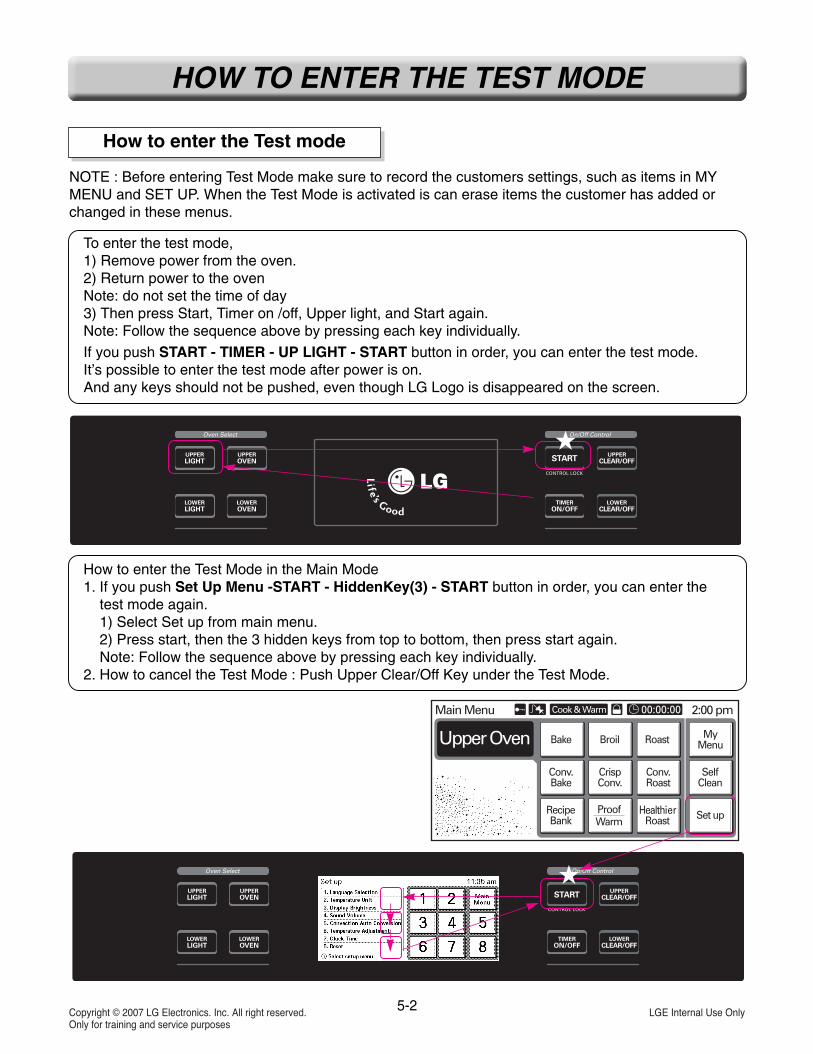
How to enter the Test mode
To enter the test mode, 1) Remove power from the oven.2) Return power to the ovenNote: do not set the time of day3) Then press Start, Timer on /off, Upper light, and Start again.Note: Follow the sequence above by pressing each key individually.
If you push START - TIMER - UP LIGHT - START button in order, you can enter the test mode.It’s possible to enter the test mode after power is on.And any keys should not be pushed, even though LG Logo is disappeared on the screen.
NOTE : Before entering Test Mode make sure to record the customers settings, such as items in MYMENU and SET UP. When the Test Mode is activated is can erase items the customer has added orchanged in these menus.
How to enter the Test Mode in the Main Mode1. If you push Set Up Menu -START - HiddenKey(3) - START button in order, you can enter the
test mode again.1) Select Set up from main menu.2) Press start, then the 3 hidden keys from top to bottom, then press start again.Note: Follow the sequence above by pressing each key individually.
2. How to cancel the Test Mode : Push Upper Clear/Off Key under the Test Mode.

5-3
SAFETY CAUTION & ERROR CODE SUMMARY
1.1 Safety Caution
• Normal State is power OFF, unless described differently as power ON.
1.2 Error Code Summary
Code Description Operation
F-1
F-2
F-3
F-4
F-5
F-6
F-8
F-9
F-10
F-11
F-12
F-16
F-19
F-20
Opened Sensor(Upper)
Shorted Sensor(Upper)
Touch SensorKey Error
Opened Sensor(Lower)
Shorted Sensor(Lower)
Oven hot
Temp Probe(Upper)
No heating(Upper)
Door Lock Fail(Upper)
Comm Error
EEPROM Error
Oven hot(Lower)
No heating(Lower)
Door Lock Fail(Lower)
Upper Oven Thermistor remain open for over 1 min, after cookstarts
Upper Oven Thermistor is shorted for over 1 min after cook starts
When touch senor key has some error for >= 60 second.
Lower Oven Thermistor remain open for over 1 min, after cookstarts
Lower Oven Thermistor is shorted for over 1 min after cook starts
Upper Oven temperature is over 650˚F / 343˚C continuouslyduring 2 minutes on cooking.
Upper Temp Probe Thermistor is shorted for over 1 min after cookstarts
If oven temperature in the UPPER oven does not exceed 150˚F /66˚C in less than 5 minutes.
Upper Oven in case of Door Lock Failure
Communication error between user interface and main PCB forover 10 seconds.
EEPROM Error for My Menu.
Lower Oven temperature is over 650˚F / 343˚C continuouslyduring 2 minutes on cooking.
If oven temperature in the LOWER oven does not exceed 150˚F /66˚C in less than 5 minutes.
Lower Oven in case of Door Lock Failure

5-4
CHECKING FLOW CHART BY FAILURE MODE
Symptom Check Point
1. Dead2. No Display
1. Check for power to wall oven 2. Check the thermostat.3. Check the Transformer.4. Check the System and Display
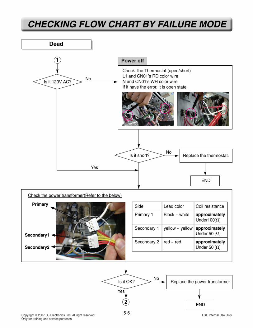
Dead

5-5
CHECKING FLOW CHART BY FAILURE MODE
Check for loose connector’s.or disconnect CN01, CN02, CN03between system(CN10) and display(CN10)
Check AC input voltage of oven System PCB- CN01 (pin 1 and 3) Should have 120VAC.
No display
Connector is ok? Fix the connection
END
L1
N
Power off
Power On
1
No
Yes
Dead
5-6
CHECKING FLOW CHART BY FAILURE MODE
Check the power transformer(Refer to the below)
Primary
Secondary1
Secondary2
Side Lead color Coil resistance
Primary 1 Black ~ white approximately Under100[Ω]
Secondary 1 yellow ~ yellow approximately Under 50 [Ω]
Secondary 2 red ~ red approximatelyUnder 50 [Ω]
Is it OK?
Is it short?
Is it 120V AC?
Replace the thermostat.
END
2
1
No
No
Replace the power transformer
END
No
Check the Thermostat (open/short)L1 and CN01’s RD color wireN and CN01’s WH color wireIf it have the error, it is open state.
Yes
Yes
Power off
Dead

5-7
CHECKING FLOW CHART BY FAILURE MODE
3
2
Check the System’s Vcc – CN10’s pin11(Vcc) and pin9 (GND)
The voltage should be 4.5 VDC ~ 5.8 VDC.
Check the Display’s Vcc–CN10’s pin11(Vcc) and pin9 (GND) or C228 or C19
Don’t remove the harness
The voltage should be 4.5 VDC ~ 5.8 VDC
Power On
Is the voltage OK? Replace the system PCB
END
No
Dead

5-8
CHECKING FLOW CHART BY FAILURE MODE
3
Is the voltage OK? Replace the Display PCB
Check the System’s PCB
Replace the Display PCB
END
END
No
Yes
Dead

5-9
CHECKING FLOW CHART BY FAILURE MODE
Symptom Check Point
No heating 1. Check Electric wiring and PCB’s connection. 2. Check the thermostat.3. Check the heater’s resistor.4. Check the sensor.
-. Check : Elements Resistance ohms
Symptom : No heating
-. Check : Open/Short
Symptom : No heating
-. Check : connection
Symptom : No heating
L2
Oven does not heat (including F-9, F-19 error)

5-10
CHECKING FLOW CHART BY FAILURE MODE
Disconnect power
Check the thermostat open/shortbetween DLB Relay’s L2 and L2 (BK wire)If it have the error, it is open state.
Check the electric wire connectionDLB and and harness of Relay and each heater’s connection.And system PCB and Relay PCB(CN11, CN12)Loose connection and disconnection
Is it short?
END
No
Yes
Replace the thermostat.
Oven does not heat (including F-9, F-19 error)
No heating(including F-9/F-19 error)
Is connection OK? Fix the connection
END
No
Yes
L2
L2
1

Resistor Min Max
Bake 22.0 35.0
Convection 25.0 42.0
Inner broil 22.0 35.0
Outer broil 35.0 46.0
5-11
CHECKING FLOW CHART BY FAILURE MODE
Oven does not heat (including F-9, F-19 error)
Measure the Resistor of each heaterBetween the DLB Relay’s L2 and each heater Relay’s Harness point of Figure 1 (①, ②, ③, ④ and ⑤)(measure the resistance after cooling down) Normal:
Figure 1
L2
BakeBakeBakeBakeBakeBakeBakeBakeBakeBakeBakeBakeBakeBakeBakeBakeBakeBake
Inner BroilInner BroilInner BroilInner BroilInner BroilInner BroilInner BroilInner BroilInner BroilInner BroilInner BroilInner BroilInner BroilInner BroilInner BroilInner BroilInner BroilInner Broil
ConvectionConvectionConvectionConvectionConvectionConvectionConvectionConvectionConvectionConvectionConvectionConvectionConvectionConvectionConvectionConvectionConvectionConvection
Out BroilOut BroilOut BroilOut BroilOut BroilOut BroilOut BroilOut BroilOut BroilOut BroilOut BroilOut BroilOut BroilOut BroilOut BroilOut BroilOut BroilOut Broil
If it is not correct,Measure heater resistance directly.
Is resistor value OK?
END
No
Yes
Replace the error heater
2
1

Replace the Sensor
5-12
CHECKING FLOW CHART BY FAILURE MODE
Check the thermistor using the test mode 4.DiagnosisUpper oven sensor, Lower oven sensorAfter value the sensor value are 70˚F ~ 90˚F(at 24˚C)
Oven does not heat (including F-9, F-19 error)
2
Power On
Check the thermistor’s resistorCN04 pin3, 4 and CN05Normal: approximately 1.09 kΩ
Power Off
Is the value OK?No
Yes
Is the value OK?
OK?
Replace the Relay PCB END
END
No
UpperUpperUpperUpperUpperUpperUpperUpperUpperUpperUpperUpperUpperUpperUpperUpperUpperUpper LowerLowerLowerLowerLowerLowerLowerLowerLowerLowerLowerLowerLowerLowerLowerLowerLowerLower
Replace the System PCBNo
Yes
Yes

5-13
CHECKING FLOW CHART BY FAILURE MODE
Replace the control supporter(ITO film+Glass touch PCB)
Check the connection key pcb’s CN7 and between display pcb and key pcb(CN6)
Is Key operating OK?No
Yes
Replace the Display pcb
Not operating Key (including F-3 error)
Key operating fail(F-3)
Is connection OK? Fix the connectionNo
Yes
END
CN7
CN6

5-14
CHECKING FLOW CHART BY FAILURE MODE
No
Yes
Lock failed (F-10/20 error)
Disconnect power
Fix the connection
END
Just after self-clean start,the door lock motor starts to rotate. During that time if the door lock switch does notoperate properly after rotating twice, then supervising circuit detects a Door Lock failure and the F-10, F-20error code appears.
Check the terminal loose of micro switch and door locking motor
Is the connection OK?
lock system failure(including F-10, F-20 error)
1

5-15
CHECKING FLOW CHART BY FAILURE MODE
lock system failure(including F-10, F-20 error)
OK?
Yes
No
Replace the locking motor
END
Is the connection OK?
Yes
No
OK?
Yes
No
OK?
Yes
Fix the connection
Replace the Relay PCB
Replace the System PCB
Check the Relay PCB’s electric connection (CN01, CN03)Check the connection between system
PCB and relay PCB(CN11, CN12)
END
END
Check the loose connector (Oven main PCB CN08)
Check the locking motor (measure the resistance)Normal : approximately 2.6 kΩAbnormal : infinite or below 5 Ω
1 2 3
1

5-16
CHECKING FLOW CHART BY FAILURE MODE
Replace the Sensor
Check the thermistor using the test mode 4.DiagnosisUpper oven sensor, Lower oven sensorAfter value the sensor value are 70˚F~90˚F(at 24˚C)
Check the thermistor’s resistorCN04 pin3, 4 and CN05Normal: approximately 1.09 kΩ
Power Off
Is the value OK?No
Yes
Is the value OK?
Replace the system PCB
END
No
Yes
Oven Thermistor failed(including F-1, F-2, F-4, F-5 error)
oven sensing failed(including sensor error)
UpperUpperUpperUpperUpperUpperUpperUpperUpperUpperUpperUpperUpperUpperUpperUpperUpperUpper LowerLowerLowerLowerLowerLowerLowerLowerLowerLowerLowerLowerLowerLowerLowerLowerLowerLower

5-17
CHECKING FLOW CHART BY FAILURE MODE
Remove the relay PCB harnessand pull the relay PCB forward from case
Oven too hot (including F-6/F-16 error)
Oven is too hot(F-6/16 error)
Disconnect power
Check the L1(TAB1, 18/TAB6, 20) and all the heater relay welded or not.(AND measure the resistance)
L1
Welded Normal
Continuity Infinite
Normal?
Yes
No
Replace the relay PCBReplace the system PCB
END

5-18
CHECKING FLOW CHART BY FAILURE MODE
Fix the connection
Check the PCB’s test modeCheck the 4.DiagnosisCommunication checkOk or NG.
OK?No
Yes
Is the connection OK?
Check the test mode 1 power check
END
No
Yes
Communication error →→ F-10 error
F-10 error (communication error)
Check the connection between the system and display(CN10)
Do they operate theHeaters?
Yes
No
Replace the System PCBReplace the Display PCB
END
6-1
SCHEMATIC DIAGRAM

6-2
STRIP CIRCUITSSTRIP CIRCUITS
Complete the following steps before checking electric oven circuit : 1.Check the line voltage, household fuse or circuit breaker.2.Check for loose wiring or mis-wiring within electric range.
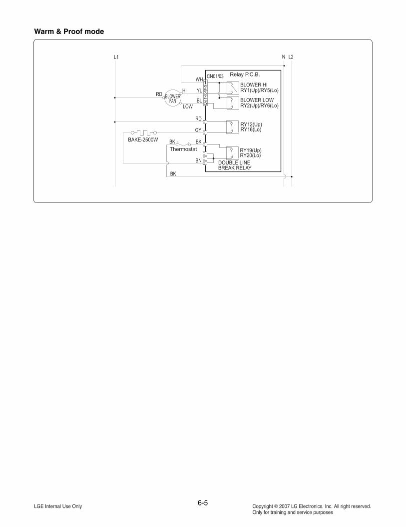
NOTE: The following individual circuits are for use in diagnosis, and are shown in the ON position.NOTE: “(Up)” and “(Lo)” denote Upper oven and Lower oven connections.
Full Broil mode
Center Broil mode

6-3
Crisp Convection mode
Conv. Bake & Conv. Roast mode
Note: In case of Bake mode, the convection fan will operate only for preheating.

6-4
Bake & Roast mode
Self Clean mode
• CIRCUIT SHOWN WITH ALL HEATERS SET TO “OFF”.• DOOR LOCK MOTOR AND BLOWER(LOW) SET TO “ON”• OVEN DOORS CLOSED AND UNLOCKED.
NOTE: SELF CLEAN CAN ONLY BE RUN IN EITHER THEUPPER OR LOWER OVEN, SELF CLEAN CAN NOTBE SIMULTANEOUSLY IN THE UPPER AND LOWEROVENS.
6-5
Warm & Proof mode

-7-1-
EXPLODED VIEW
#EV#
INTRODUCTION
DOOR PARTS
CONTROLLER PARTS
CAVITY PARTS

-7-2-
#EV#
DOOR PARTS
1009
1030 1401
11201121
1703
1008
W144W144
W144
1000
1040
W225
W225
W257
W256
W256
1402
1703
1704
W144
W144
W256

-7-3-
#EV#
CONTROLLER PARTS
2381
2038
20502006
2119
2118
W258
W108
W105
2009
W105

-7-4-
UPPER CAVITY PARTS
W144
W144W235
W144
W144
W104
W144
W144
W144
W144
W144
W144
W144
W144
W104
W144
W105
W144
W144
W144
W231
W231
W231
W231
W231
W231
W144
W144
W144
W237
5504
5070
30063006
5116
3062
5450
5517
5124
5073
5073
5701
5117
3006
5414
5014
5010
561155035717
5718
5506
5505
5449
5506
5507
5562
5550
5540
5090
5550
5550
5514
5441
5451
5561
5505
5449
5513
5602
5601
5601
3022
5021
5512
5512
5516
5515
5515
5522
5401
W230W259
W259
W259
W230
4002
5407
W232
W233
5406
5041
5001
5561
W144
W144
W144
W144
W144
W144
W144
W144
W144
W144
W144
W230
W146
5508
W241
W236
5410
#EV#

-7-5-
LOWER CAVITY PARTS
5441
5019
5451
5449
5512
6001
5512
5516
5515
5515
5522
W230
W230
4002
W144W144
W144 W144
W144
W144
W144
W144
W144W144
W144
W231
W231
W231
W231
W231
W231
5562
5507
55175124 5414
5703
5119
5118
5713
5702
55505540
5096
5095
5550
5550
5514
5513
5602
5601
5601
3022
5021
5401
5407
W232
W233
5406
5561
W144
5561
5449
3062 3006
3006
3006
5450
W144
W144
W144W144
W144
W144
W144
W144
W144
W104
W104
W144
W144
W144
W144
5440
5073
5073
W230
W259
W259
W259
#EV#

-7-6-
ASSEMBLY
W144
W144
W144
W144
W144
W144
W144
3029
3605
3603
3604
5723
5097
5545
5535
5527
1005
1005
20043311
3602
3601
3013
3013
W144
W144
W144
W144
W144
W144
W144
W121
W144
W144
W144
W144
3018
3511
3044
3144
50803312
W144
W144
W144
#EV#
